Article

Design for Additive Manufacturing of Lattice Structures for Functional Integration of Thermal Management and Shock Absorption

“Enzo Ferrari” Department of Engineering, University of Modena and Reggio Emilia, 41125 Modena, Italy
*
Author to whom correspondence should be addressed.
J. Manuf. Mater. Process. 2025, 9(1), 24; https://doi.org/10.3390/jmmp9010024
Submission received: 10 December 2024 / Revised: 4 January 2025 / Accepted: 10 January 2025 / Published: 14 January 2025

Abstract

:
Design optimization through the integration of multiple functions into a single part is a highly effective strategy to reduce costs, simplify assembly, improve performance, and reduce weight. Additive manufacturing facilitates the production of complex structures by allowing parts consolidation, resulting in optimized designs, where multiple functions are integrated into a single component. This study presents a design for additive manufacturing method for integrating multiple lattice structures to achieve thermal management and shock absorption functions. The method follows modeling and simulation phases for dimensioning and optimizing solutions to deliver the design functions at different macro- and mesoscale levels. Hierarchical complexity was leveraged to design the two-levels structure in a single part, each delivering a specific function. Specifically, the external layer addresses energy absorption and thermal insulation, while the internal layer acts as a thermal battery by incorporating a phase change material. The design of a container carried by an unmanned aerial vehicle for the transport of healthcare and biological materials is presented. The container is shock-resistant and can maintain the content at 4 ± 2 °C for at least 1 h. As it operates passively without the need for additional energy-consuming devices, it is easy to operate and contributes to increased flight autonomy. A flight mission experiment for urgent transport of blood bags confirmed the capability of the container to preserve blood integrity. This case study demonstrates that the two-layer lattice structure design represents a highly efficient approach to multifunctional design optimization.

1. Introduction

The combination of multiple functions within a single part is important when it is necessary to optimize its dimensions and weight and to improve overall efficiency. Additive manufacturing (AM) has been widely recognized as an effective technique to build multifunctional parts. Possible parts consolidation and functional integration are considered key features enabled by AM in many research works [1,2,3,4,5]. This approach, referred to as integrated design [6], functional integration [7], or design consolidation [8], is one of the design guidelines for a part produced by AM in the ISO 52900 series standards. In particular, designing a structure that simultaneously addresses thermal management and shock absorption functions requires careful consideration of material selection, geometry optimization, and integration of specific features [4].
In addition to the material selection, product optimization can add features to take full advantage of its base properties within available space and weight [9]. In fact, AM also allows for design complexity at different scales via hierarchical structures. A feature at one size scale can have smaller features added, and to each of those smaller features, further smaller features added [5]. This has been considered a key design opportunity [10,11], although it introduces additional design challenges [12].
Cellular and lattice structures are used in the literature to maximize the surface area for improved thermal dissipation [13], to incorporate internal channels for fluid circulation, to enhance active cooling, or to promote convective heat transfer by allowing air to flow through and dissipating heat effectively. On the other hand, voids and spongy structures can also be optimized with the opposite goal of creating barriers to heat transfer [14]. The combination of lattice cells, such as cubic, diamond, or gyroid, can balance structural integrity, weight, and shock absorption capabilities [15,16]. Shock absorption elements can also be integrated within the lattice, such as resilient beams or structures that deform upon impact [17]. Furthermore, the density and thickness of lattice cells can be varied to provide regions with different levels of stiffness, achieving the desired balance between stiffness and energy absorption. Cellular and lattice structures, at a high level of abstraction, can be tuned to design metamaterials, which are a class of engineered materials that exhibit tailored mechanical properties derived from their designed architectures [18].
Components’ structures can be further optimized for weight. Topology optimization tasks can provide the optimal material distribution within a domain considering the design objectives and the manufacturing constraints [2]. Approaches to combine topology optimization and lattice structure design are current research topics [19]. In fact, the design could be optimized at different hierarchical scales, generally referred to as macroscale, mesoscale, and microscale [20,21]. The literature provides some strategies of multi-scale design approaches for optimized design at different hierarchical scales for structural purposes [22,23,24,25].
The present research focuses on a design for additive manufacturing (DfAM) method for the optimization of lattice structures for both thermal management and shock absorption. The method follows the systematic design approach, ensuring that all aspects are appropriately considered and addressed. Systematic design methods have been standardized to efficiently guide product development [26,27] or improve product and process design from specific engineering perspectives [28]. DfAM is a technique to effectively exploit the potential of AM [29]. Since its first mention [30], DfAM has included many approaches, ranging from conceptual guidelines, design rules, build strategies, and even frameworks to improve AM at system level [3,4,6,20,31,32,33,34]. Functional integration and hierarchical and cellular structures are all aspects addressed by DfAM.
A case study on a container of an unmanned aerial vehicle (UAV) is presented. The UAV is dedicated to the transportation of healthcare products and biological materials, avoiding the usual car traffic and reducing delivery times. The main design objectives are to preserve the transported material by keeping it within a specific and narrow temperature range and to avoid any possible leakage of potentially infectious material in case of an accident.
The paper is organized as follows. Section 2 analyzes the scientific problem and describes the proposed design method, Section 3 introduces the computer-based simulations necessary in the design phases, Section 4 describes the application of the approach to the case study, and Section 5 contains the concluding remarks.

2. Materials and Methods

This work focuses on the integration of thermal maintenance with crash protection functions for a container. The method follows a sequential process shown in Figure 1, where each function, denoted as F1, F2, …, Fn, is addressed by the part structure at an increasing level of detail with a multiscale design approach [20,21,24,25]. The design starts with a functional analysis to define the design requirements and constraints and possible solution principles at conceptual level. A broader macroscale design aims to integrate and arrange the functional carriers within the design space. Subsequently, a more specific mesoscale design is needed to optimize the functional regions. Finally, the validation and build preparation stages complete the method to ensure the expected performance and manufacturability.
Thermal maintenance can be further analyzed by considering the sub-functions of thermal insulation and temperature conditioning. Crash protection must be achieved to preserve the contents from leakage and damage and to avoid contamination of the external environment. A basic specification is lightweighting, which has a significant impact on the efficiency of UAVs.

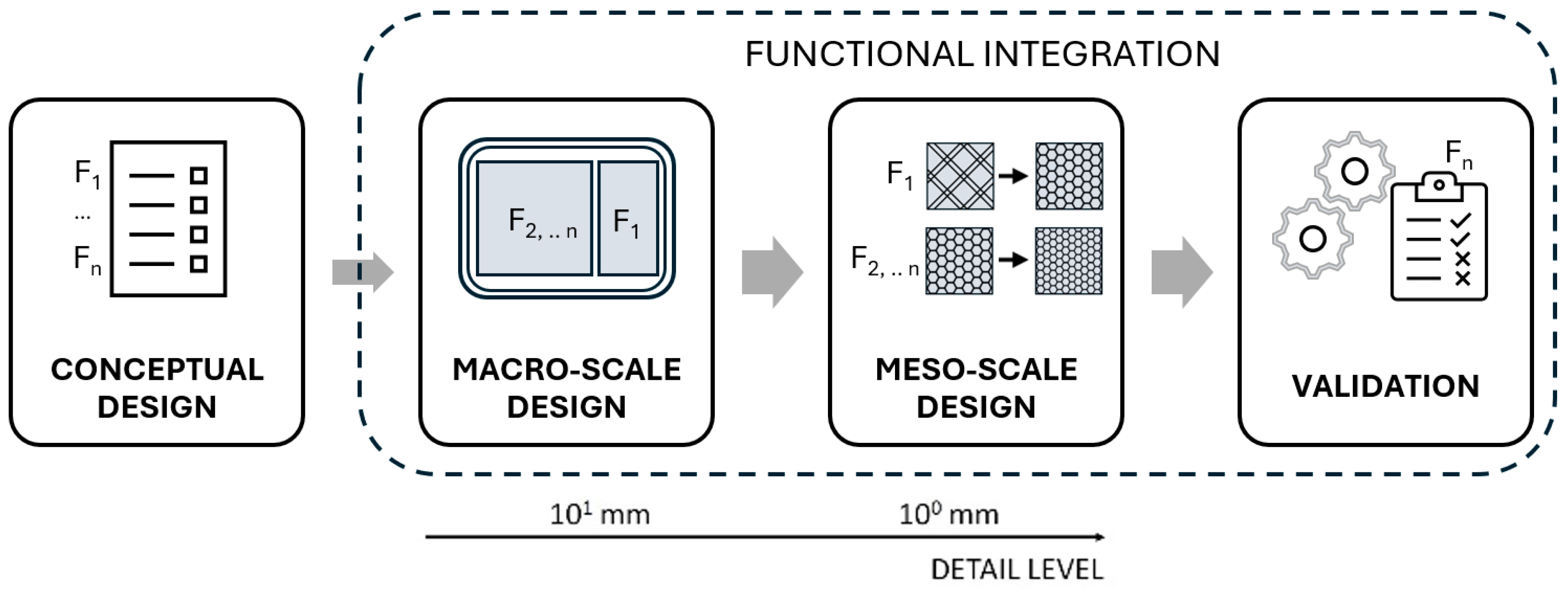
2.1. Conceptual Design

Thermal insulation of walls can be achieved by using insulating materials such as polyurethane, usually inserted inside sandwich panels, or super-insulators such as vacuum insulated panels (VIPs) [35]. However, research on lattice structures also demonstrates their effective thermal insulation properties [13,14].
Temperature conditioning of a container can be achieved using active or passive cooling systems. The former consists of devices that use electrical energy to transfer heat from a source to a sink. This solution can be very effective, but in the application to UAVs it implies lower energy efficiency and greater complexity due to the need for additional devices. Passive systems are based on phase change materials (PCMs), which reversibly absorb and release a large amount of the latent heat during the phase transitions of melting and freezing, making them highly useful for temperature regulation. PCMs ensure a significant reduction in energy consumption for conditioning since they do not require an external energy supply [36]. Comparing between the selection of active and passive systems is based on a trade-off between energy efficiency, additional weight, and simplicity. PCM materials are usually available in plates, but when in liquid phase they can also fill complex geometries. Therefore, they can be stored in efficient shapes directly inside the container wall, thus reducing the overall size of the system. PCMs can be integrated into the wall layers made of lattice structures with a dedicated DfAM approach.
Crash protection can be achieved with three different design solutions. First, the content can be protected by a robust structure made of high-strength material. This solution is usually heavy and ultimately does not protect the content from strong accelerations. A second solution includes sacrificial impact absorbers, which allow the kinetic energy of the impact to be absorbed. Absorbers made of cellular structures such as honeycombs can be quite bulky to fit into the overall system. Lattice structures have been widely studied for their energy-absorbing properties and many different shapes can be adapted to different designs [17]. Furthermore, 3D lattice structures based on plates and shells are promising both for their energy-absorbing properties and manufacturability with polymers, since these patterns are already integrated into build processors for AM machines.
Nature provides excellent examples of optimized lightweight structures, such as the branching forms of plants and the porosity of bones, which traditional manufacturing struggles to replicate [37]. AM overcomes these limitations, enabling the creation of complex geometries. Lattice structures can provide improved performance and material efficiency and can be used in such bio-inspired designs.
Besides the analysis of systems’ functions and possible solution principles, the design requirements and constraints must be defined, considering both physical boundary conditions and regulatory aspects.

2.2. Embodiment Design

At system level, material and process selection should be performed as described in established [4,32] and more recent [34] DfAM frameworks. By analyzing fabrication capabilities, DfAM guidelines and rules can be applied to guide the design. At the macroscale, the total available space is distributed to the different functions that must be provided by the system. Thermal management at this macroscale is designed to provide the function tailored to the container mission. Heuristic and analytical methods can be used to preliminarily define function carriers of the system. Typical and worst-case missions must also be simulated via model-based design (MBD) to meet the thermal management specifications. Active cooling results in an unfeasible option for demanding lightweight applications, considering that a small quantity of PCM would be sufficient. Next, the design focuses on careful material selection and their distribution in the system. The main material that will be used for AM must be accurately selected to comply with all macro- and meso-requirements for resistance. In addition, low thermal conductivity is desired to ensure thermal insulation.
For the resistance of the structure, high-strength materials should be chosen. Low thermal conductivity is also a desirable property to improve insulation and thus reduce the power of any conditioning. Some polymers combine these characteristics and could be suitable options, such as polyurethane (PU), polyethylene terephthalate (PET), or even polyetheretherketone (PEEK). Among additively manufactured polymers, acrylonitrile butadiene styrene (ABS), polylactic acid (PLA), polyamides (PA), but also thermoplastic polyurethane (TPU) and polyethylene terephthalate glycol (PETG) are the most common [38,39]. PEEK and polyetherimide (PEI) technopolymers provide excellent strength-to-weight ratios [40], in the range of 70–80 MPa/(g/cm3). However, their manufacturing is complex and expensive. Optimal results, such as 40 MPa/(g/cm3), can also be achieved with the more common PLA, PETG, and ABS [40]. Regarding toughness, PA provides superior results, while PLA suffers from brittleness, even when a tough grade is available. Furthermore, PLA, PETG, and ABS provide similar or lower thermal conductivity values than technopolymers, around 0.2 W/m·K [41]. The material must also show appropriate thermal stability. In this case, while technopolymers such as PEEK and PEI offer a higher glass transition temperature of up to 200 °C, ABS and PETG values are about 100 °C and 80 °C, respectively, while PLA suffers the worst value of about 60 °C [42]. Table 1 summarizes the described characteristics of established and unconventional materials.
The macroscale design for thermal management specifically defines (i) regions to be filled with PCM for thermal stabilization and (ii) regions to be filled with lattice structures for thermal insulation. Thermal MBD simulations are used to evaluate the thermal behavior of the system with optimized functional regions with respect to the container mission.
Structures must be also designed at the macroscale for crash protection. The overall structure is designed to resist an impact and to ensure maximum energy absorption, thus preserving the critical content. Considering the structural requirements, functional elements can be included in the system and preliminarily dimensioned by analytical calculations. A reinforced and rigid compartment must be dimensioned to create a safety cell, while load paths must be directed away from the content and into deformation zones. The macroscale design for crash protection especially requires solid walls for structural strength and regions to be filled with lattice structures for shock absorption.
At the mesoscale, the cross section of the deformation zones is designed internally to achieve design objectives. Multifunctional lattice structures can be designed at mesoscale for both thermal insulation and shock absorption, thus achieving the desired functional integration. AM allows the creation of complex lattice configurations, such as cubic, tetrahedral, octet-truss, etc.
Lightweighting is also achieved by optimizing the lattice structures. An initial lattice structure is designed based on empirical or heuristic methods. Finite element analysis (FEA) is used to optimize the structure parameters, such as node connectivity, strut thickness, and overall porosity to allow the section to deform in a controlled manner, absorbing kinetic energy from the impact. Moreover, the impact scenarios must be simulated to study energy absorption performance. FEA can be used to model the stress distribution in the impact, allowing for optimization of structures, and to evaluate the impact energy absorption properties of the system with optimized functional regions. FEA can also be used to simulate conduction, convection, and radiation within the lattice structure and optimize its thermal insulation properties. Cavities to be filled with PCM can also be optimized for minimum material usage and structural integrity.
Manufacturability by AM technologies must be ensured at macro- and mesoscales. Therefore, detailed design is performed according to DfAM rules, to optimize the shape and thickness of the elements. Build preparation involves fine-tuning the process parameters to print the lattice structures of the different functional regions and achieve the expected performance. Additionally, the infill densities of the system are optimized between low-density and high-density, balancing lightweight and structural properties, respectively. The manufacturing process is finally simulated to detect any flaws and ensure the quality of the designed geometries.
Finally, Table 2 summarizes the workflow to be followed in the systematic design method used in the present research and the main results obtained.

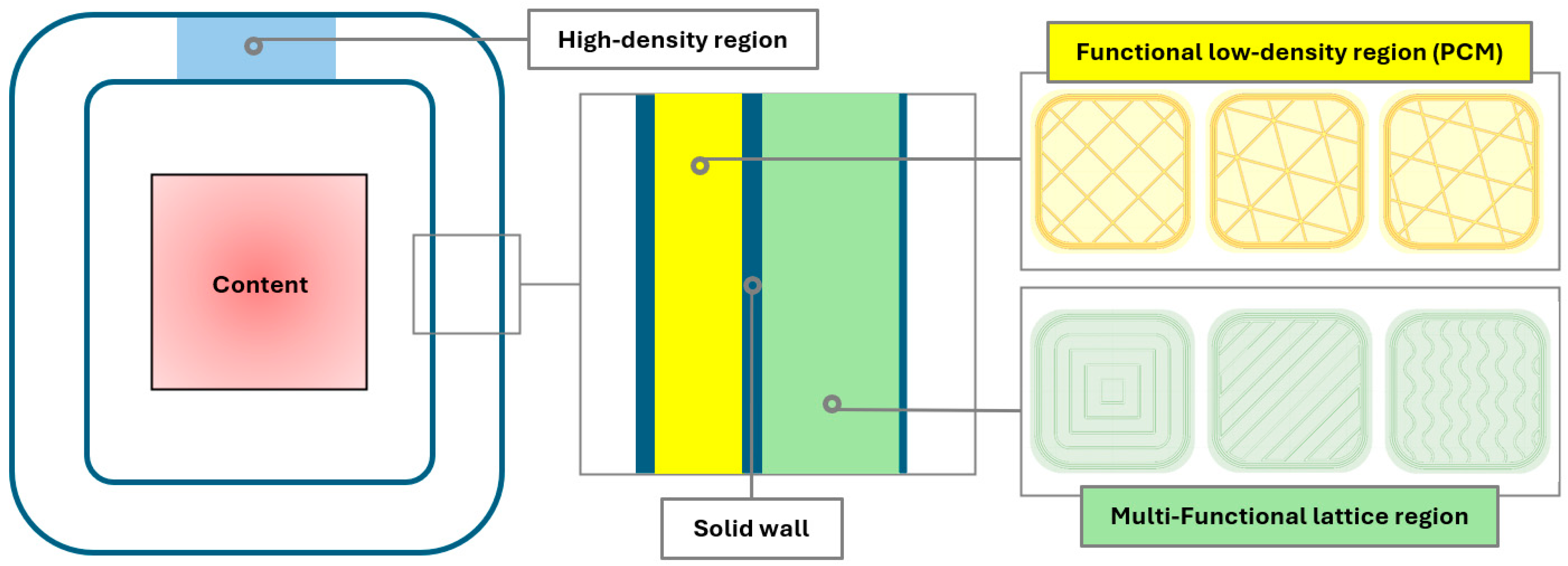
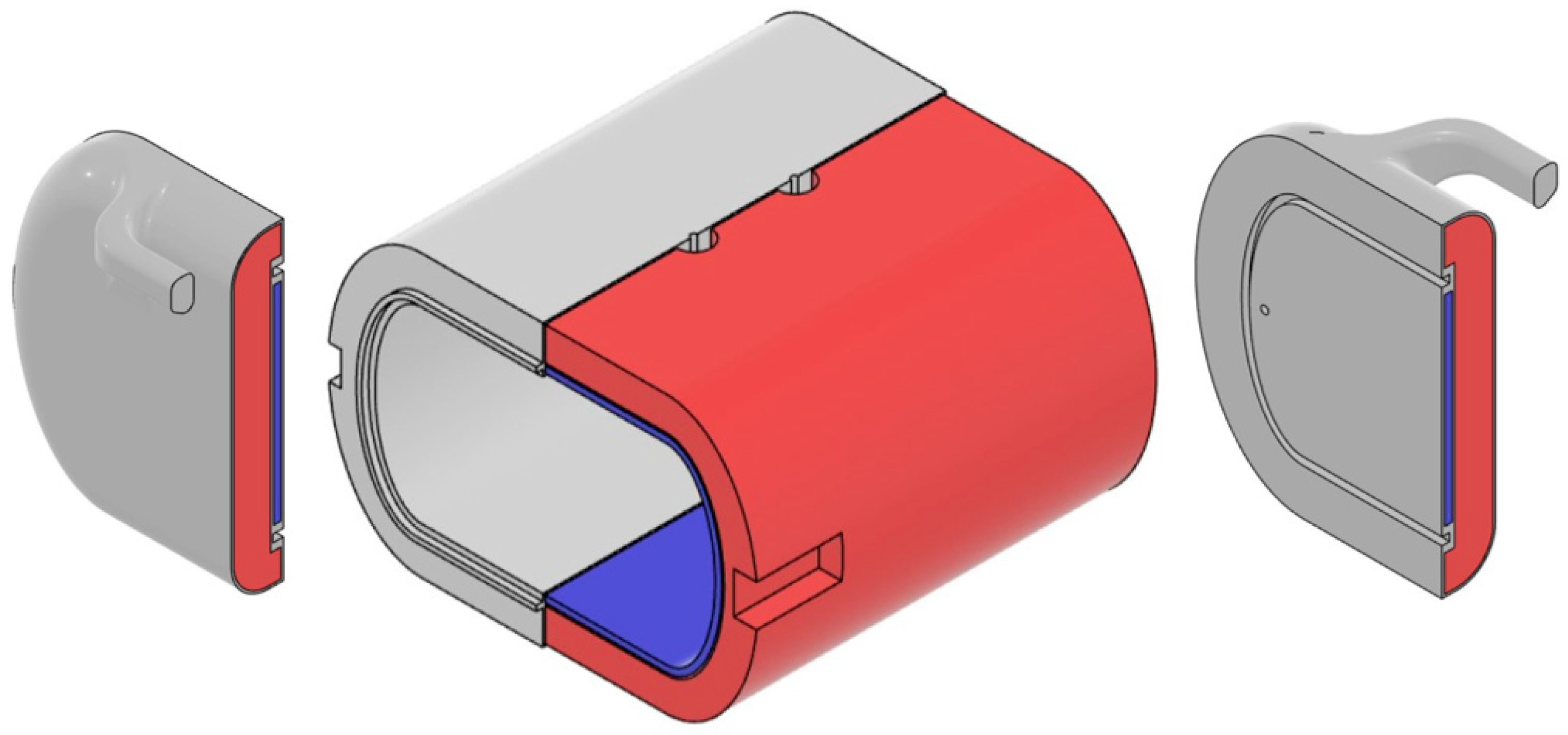
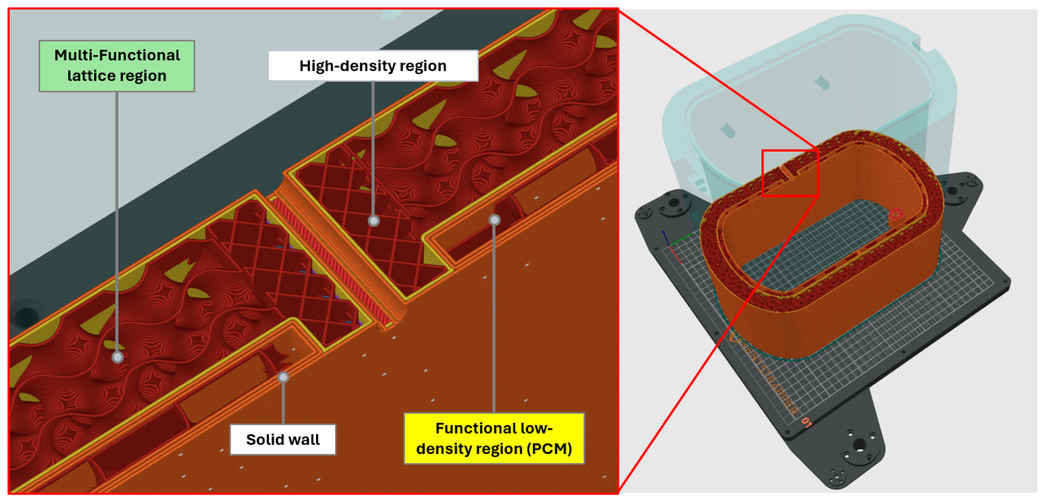
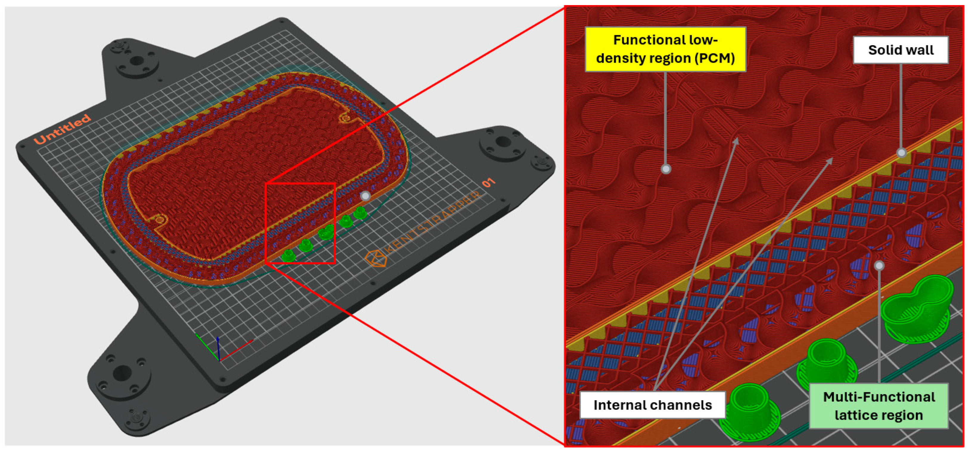
2.3. Functional Container Structure

AM allows for the integration of both the thermal and the structural functions in a single carrier, using multilayer walls, as shown in Figure 2. An outer layer with a lattice infill is used for energy absorption and thermal insulation, while the inner layer stores the PCM for thermal stabilization. The inner and outer layers are contained by solid walls.
The structure of the functional container structure is therefore composed of:
  • An outer layer with multifunctional lattice structures optimized for thermal insulation and impact energy absorption, as shown in the green region in Figure 2; the outer layer will be dimensioned at macroscale level and designed via thermal and mechanical simulations at mesoscale level;
  • An inner layer with low-density infill regions to store the PCM, shown in the yellow region; it will be dimensioned at macroscale level and optimized for minimum material usage for structural integrity and manufacturability;
  • Solid walls for structural containment of the layers and strength, shown in the blue region; they will be dimensioned for PCM waterproofness and lightweighting;
  • High-density infill regions for mechanical performance of structural features, shown in the light blue region; they will be integrated only where necessary for enhanced lightweighting.

3. Theory and Calculations

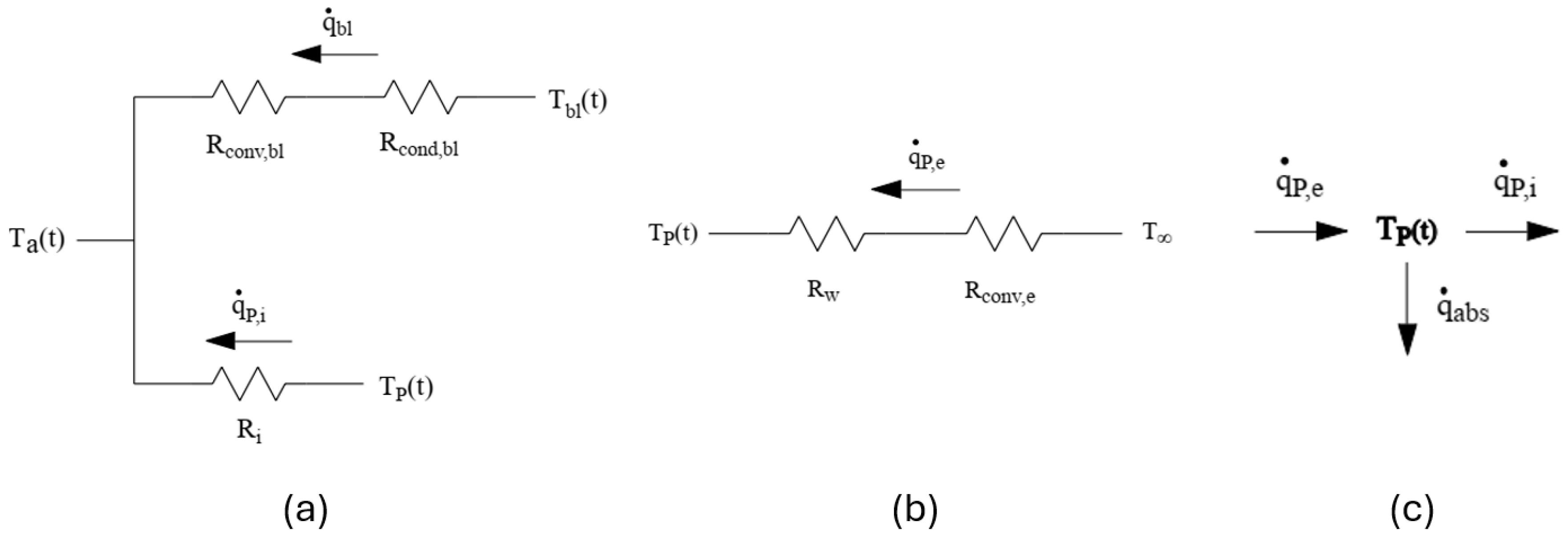
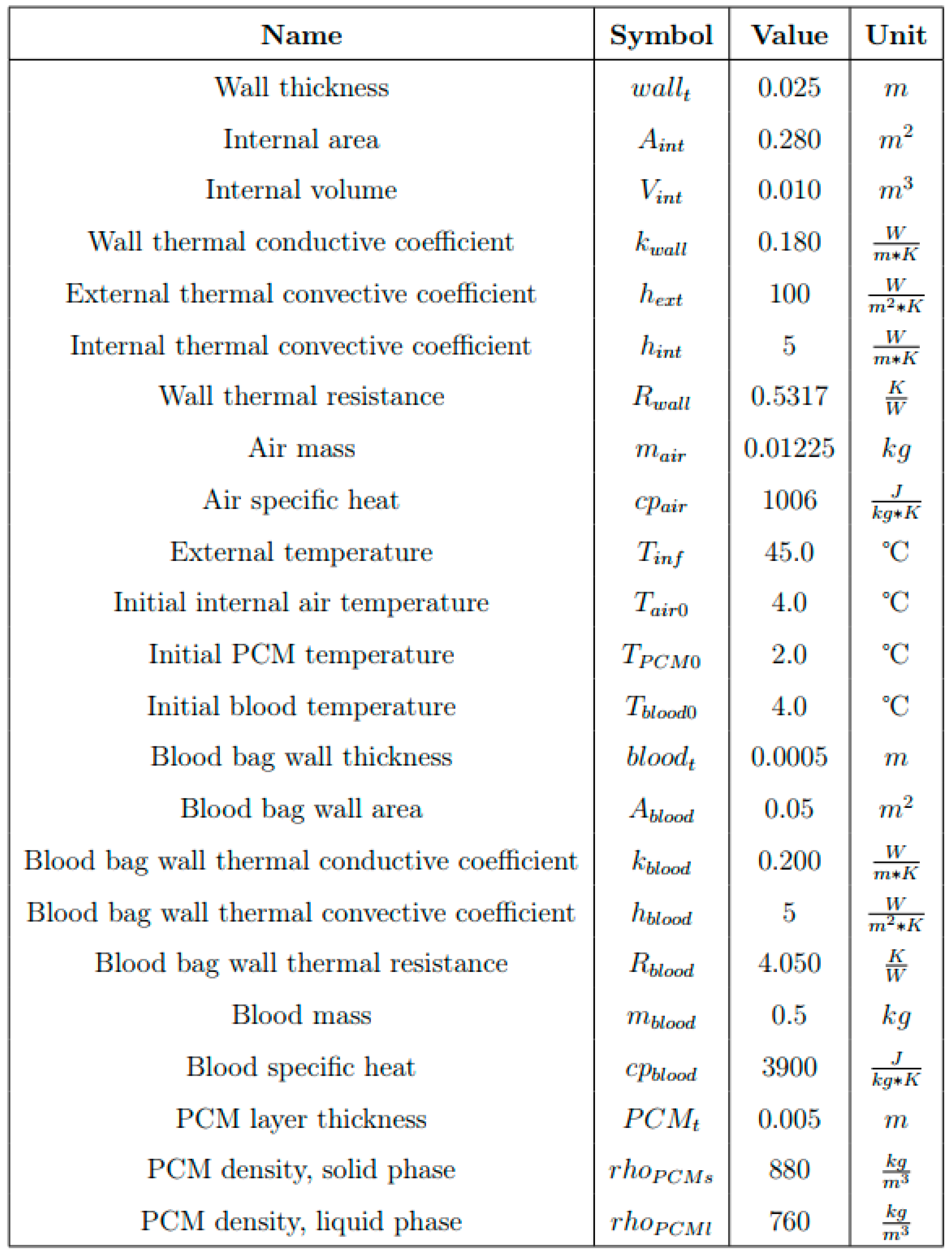
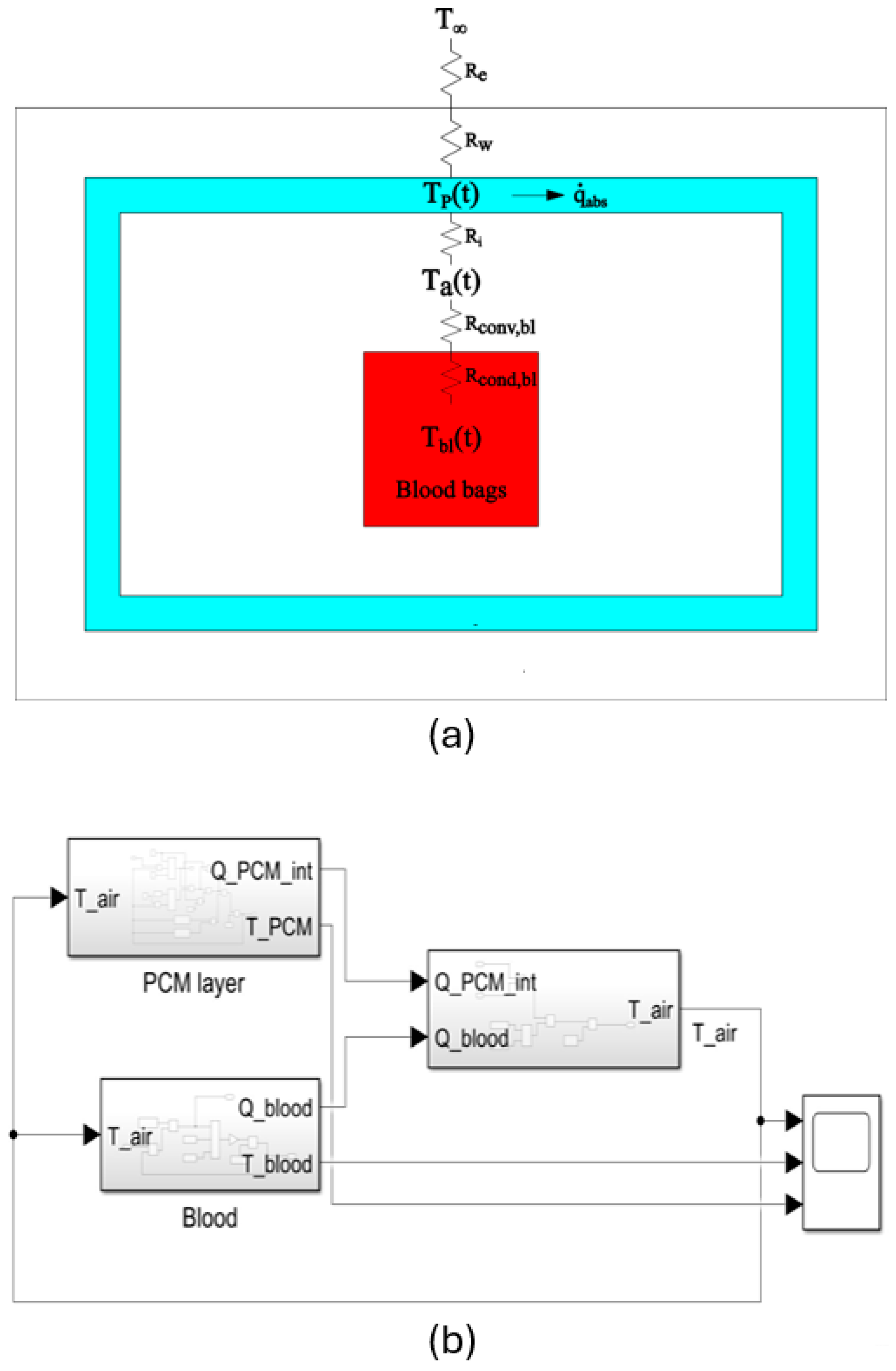
3.1. Overall Thermal Simulation

Thermal simulation in the macroscale design phase is performed on the conceptual layout of the functional container. The model uses electrical analogy, considering the temperature as potentials, the heat transfer rates as currents, and the thermal resistances as resistors. Figure 3a shows the lumped parameter model, where Tbl(t) is the content temperature, Ta(t) is the air temperature, TP(t) is the temperature of the PCM region, while Rw is the thermal resistance of the multifunctional lattice region in the outer wall layer. Since the parameters change over time, differential equations must be used. The model with the three lumped regions is implemented in the Matlab-Simulink MBD environment to simulate the mission, as shown in Figure 3b. The heat balance takes the heat flows from the boundaries as input and outputs the internal air temperature, which will be used to give feedback to the other sub-models. Special attention has been given to modeling the PCM region in the inner layer to represent the heat storage capacity, providing a specific block using a variable density between the solid and the liquid phase and enthalpy for the instantaneous temperature of the material. Further details, such as schematics and parameters, are reported in Appendix A. The main output is the temperature curve of the content inside the container over time.
This simulation allows to optimize the parameters of the PCM region, such as material selection and layer thickness, so that the specified internal temperature could be maintained throughout the target mission. Thermal insulation plays an important role in maintaining the container temperature, therefore the equivalent thermal conductivity of the multifunctional lattice in the outer layer must be previously calculated by a thermal FEA, as later described in Section 3.4.

3.2. Overall Structural Simulation

To reliably achieve the crash protection function, the detailed CAD model must be validated by FEA. To have a less computationally expensive simulation of the whole structure, equivalent material properties obtained from mesoscale analyses are used, as hereafter explained in Section 3.3. Ground impact scenarios are analyzed to define the load cases.
For each analysis, all parts of the functional container are composed of solid bodies of an equivalent material representing the bulky, hollow, and energy-absorption zones following one another. An explicit dynamic step is performed by assigning an initial velocity, gravity, and appropriate boundary conditions. Stresses and deformations can be evaluated in the model. Since the container must be leak-proof, no openings can result from the simulation. The strain energies are analyzed to evaluate the energy absorption properties of the lattice layer. The energy balance equation is written as:
EI + EVD + EFD + EKE − EW = ETOT = constant
where EI is the internal energy, EVD is the energy absorbed by viscous dissipation, EFD is the frictional dissipation energy, EKE is the kinetic energy, EW is the work carried out by external forces, and ETOT is the total energy of the system.

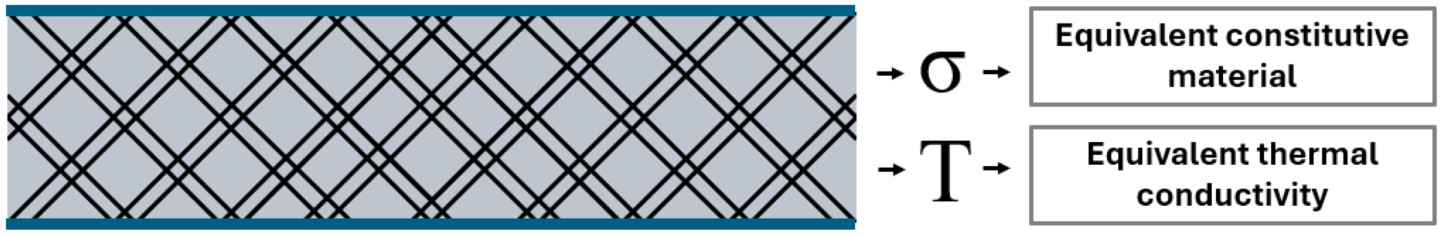
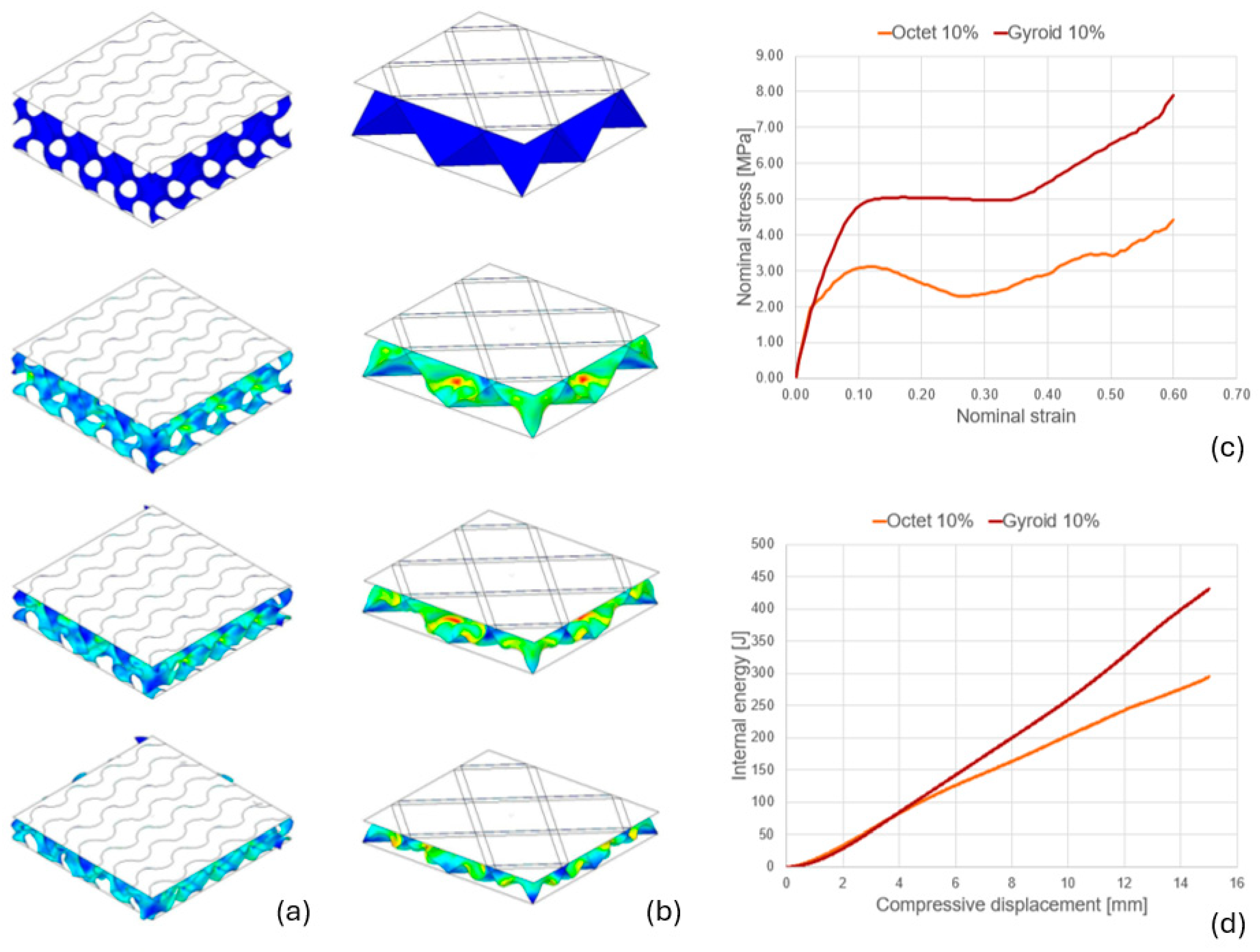
3.3. Mechanical Analysis of the Lattice Structures

Structural analysis was the first simulation required in the mesoscale design. FEA was performed here on a sandwich panel model, as shown in Figure 4, including the lattice structures and the rigid skins.
The simulation considers the following main steps:
  • Quasi-static compression simulation of lattice structures with reduced relative density;
  • Evaluation of the energy-absorption characteristics and the force-displacement curves;
  • Calibration of the selected structure to create an equivalent material with the same behavior as the tested lattice.
If the material parameters used are not rate-dependent, the quasi-static analysis can be performed with an explicit dynamic analysis by accurately defining the crushing velocity, the step duration, and a stable time increment. The approach for the simulation step was retrieved from the literature on FEA of lattice structures [43,44]. Stress–strain curves from FEA and experimental tests were analyzed to further compare the behavior of different unit cell types and relative densities. For material calibration, a stress–strain curve from a test or simulation can be imported and the parameters can be tuned to obtain a material with the same mechanical properties as the sample. The properties of an equivalent constitutive material are calculated to set up the subsequent overall FEA of the functional container.

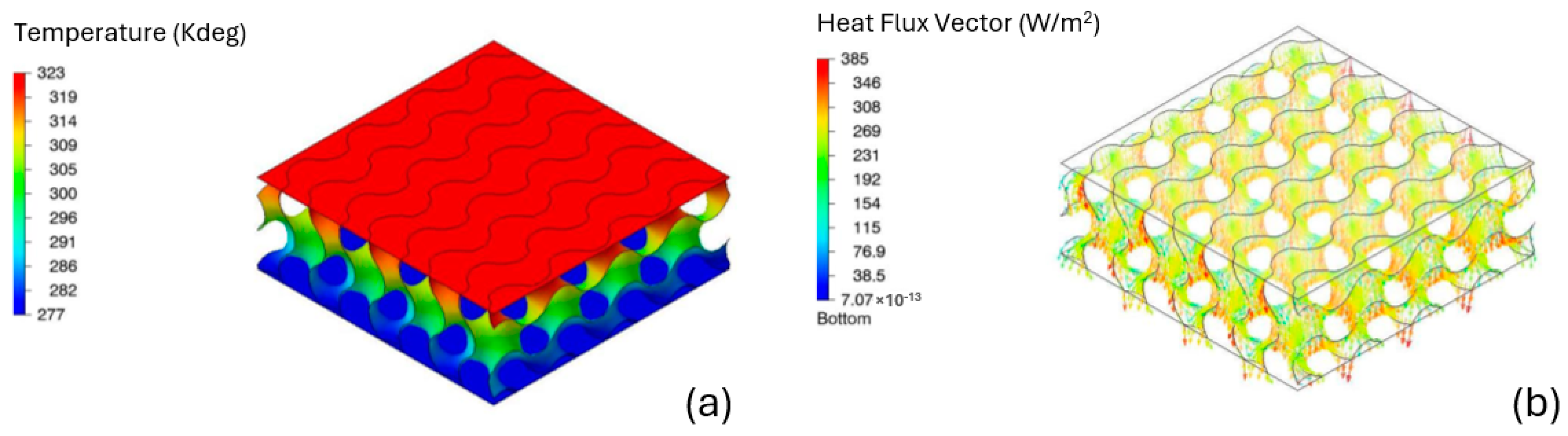
3.4. Thermal Analysis of the Lattice Structures

Thermal analysis is the second simulation required in the mesoscale design. As in the previous case, it is based on a FEA of the sandwich panel model, as shown in Figure 4. The thermal conductivity coefficient of the bulk material used in the preliminary overall thermal simulation, described in Section 3.1, must be tuned since lattice structures result in a reduced equivalent conductivity. On the other hand, convection and radiation do not contribute significantly to heat transfer in polymer structures [14].
The simulation considers the following main steps:
  • Static simulation of heat conduction, considering the boundary temperatures at the walls and the thermal conductivity of the inner material;
  • Steady-state analysis of the stable heat flux to calculate the final Qavg;
  • The equivalent conductivity is finally determined from:
λeq = Qavg·tlayer·∆T
The thermal insulation of the lattice layer can be evaluated, and the equivalent thermal conductivity can be introduced in the Simulink model for design validation.
From the analyses of the panel model described in Section 3.3 and Section 3.4, the equivalent structural and thermal properties can be extracted as outputs, as shown in Figure 4. In particular, the equivalent constitutive material is needed to set up the overall structural simulation, as described in Section 3.2, while the equivalent thermal conductivity is needed to tune the overall thermal simulation, as in Section 3.1.

4. Case Study and Results

The systematic method was applied to the design of a container to be carried by an UAV of the MO-UAS 4 Life project [45]. The UAV was specifically designed for the transport of organs, blood, or other medical equipment in emergency conditions in the province of Modena in Italy. The transport of a blood bag in perfect preservation conditions was the first test to validate the design.

4.1. Conceptual Design

Preliminary analysis of the main functions of the system is discussed in Section 2.1.; therefore, it is necessary to further define the specific design requirements and constraints of the case study.
Based on both regulatory and functional criteria, the demanded requirements were:
  • Maintenance of the blood at 4 +/− 2 °C for 1 h;
  • Crash protection to avoid any leakage of potentially hazardous material.
Wished requirements were:
  • Weight minimization for flight efficiency;
  • Ease of use for operational efficiency.
The main dimensional constraints are shown in Figure 5, and the payload was 10 kg.

4.2. Macroscale Design

The functional regions described in Section 2.3 were organized in the conceptual layout to integrate temperature maintenance and crash protection functions. Fused filament fabrication (FFF) via material extrusion (ME) was the selected polymer AM process for reliably and cost-effectively producing large parts. First, it allows processing of a plethora of thermoset polymers, as reported in Table 1, with improved mechanical properties, as opposed to vat photopolymerization or binder jetting. Furthermore, it keeps prototyping costs low, especially considering large build volumes, as opposed to powder bed fusion, or material jetting, which could be worth investigating for small batch production. Considering the design requirements and the FFF manufacturing constraints, the functional regions were modeled as shown in Figure 6. The layout consisted of the blue PCM region, the red multifunctional lattice region, and the gray non-functional region for the door, the body, and the lid. The PCM region was specifically designed to encapsulate the content, while the multifunctional lattice region was designed externally based on design constraints. The design of the parts followed the DfAM rules, considering also the orientations in the FFF manufacturing system.
The materials and dimensions of the functional regions were mainly driven by the overall structural and thermal simulations. PETG was selected for FFF since it combines properties that met the design specifications with low cost and high ease of printing. It also provided higher impact resistance, durability, and thermal stability compared to the more common PLA. Over-engineered materials such as PEEK or PEI were not selected for the following reasons: from a mechanical point of view, PETG combines sufficient resistance with inherent ductility, therefore it is suitable for absorbing impacts; from a thermal point of view, its conductivity, combined with PCM, can provide adequate thermal insulation, while thermal stability is in any case optimal for operating in non-extreme conditions; furthermore, even if not as strong as PEEK or PEI, it presents a favorable strength-to-weight ratio, which is a key requirement for the payload efficiency of UAV applications. Moreover, PETG is significantly less expensive, allowing economic viability and enabling scalability for wide adoption. Furthermore, it is compatible with widely available FFF 3D printers and has high ease of printing, with low warping and minimal need for heated enclosures, therefore not requiring high-temperature industrial 3D printers. Hence, these features add increased accessibility for prototyping and customized manufacturing in decentralized or resource-limited settings. The organic RT5HC from RUBITHERM® (Rubitherm Technologies GmbH, Imhoffweg 6, 12307 Berlin, Germany) was selected as PCM. RT5HC undergoes a phase change between 4.5 °C and 6.5 °C and provides a heat capacity of approximately 230 kJ/kg in this range. Figure 7a shows the preliminary results of the thermal simulation, based on a 5 mm PCM region and a wall heat conduction coefficient of λs = 0.180 W/(mK) for bulk PETG, considering an extreme external temperature of 50 °C. Details of the parameters and boundary conditions used in the MBD model are reported in Figure A2. Figure 7b shows the simulation results after the mesoscale design phase to validate the final design, which extended the potential duration of the mission up to 2 h.

4.3. Mesoscale Design
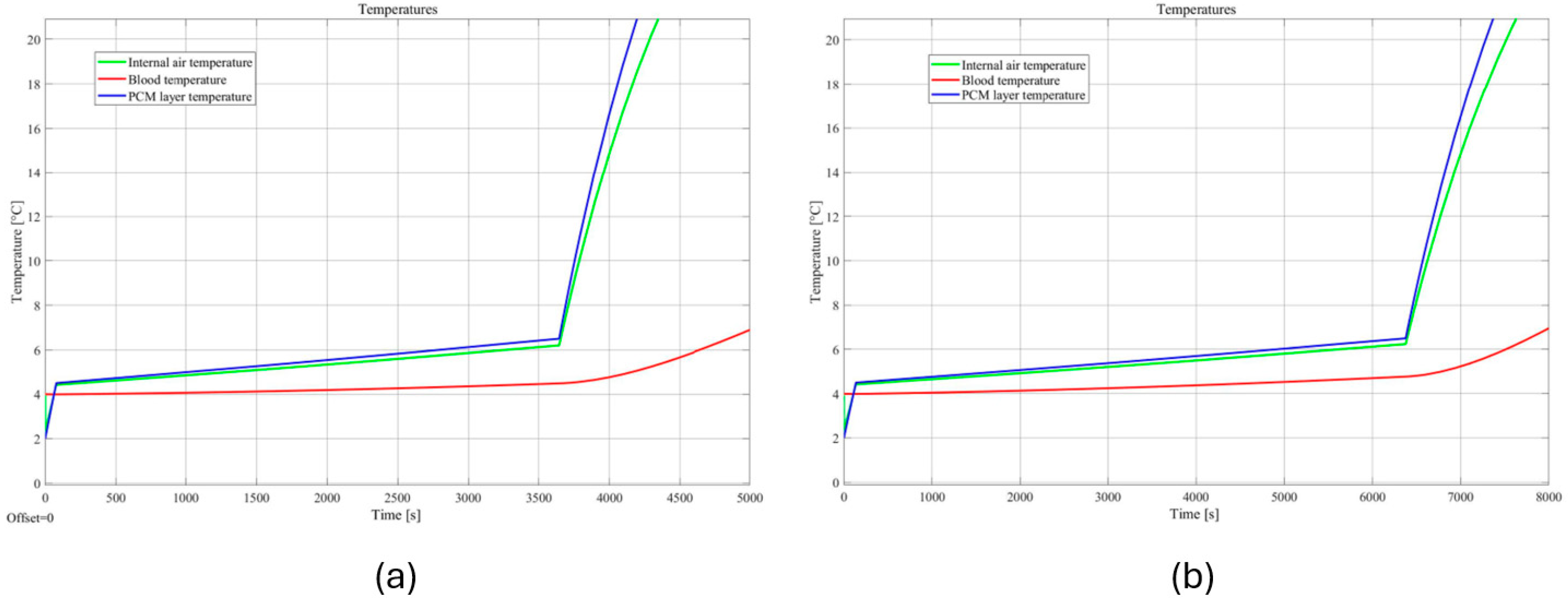
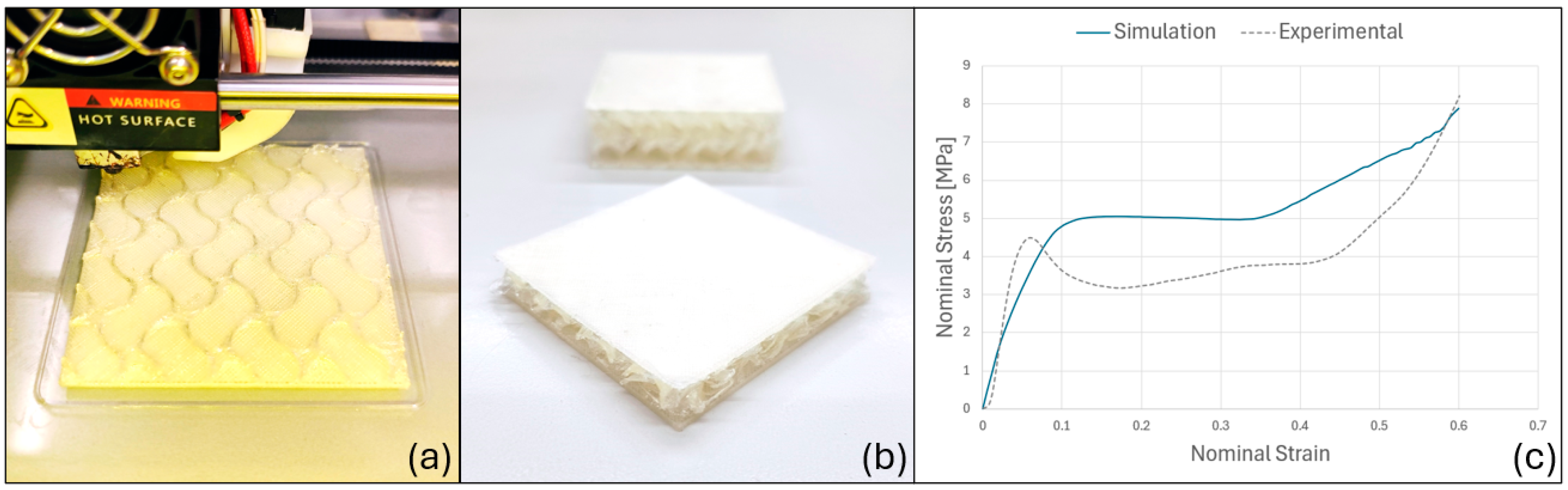
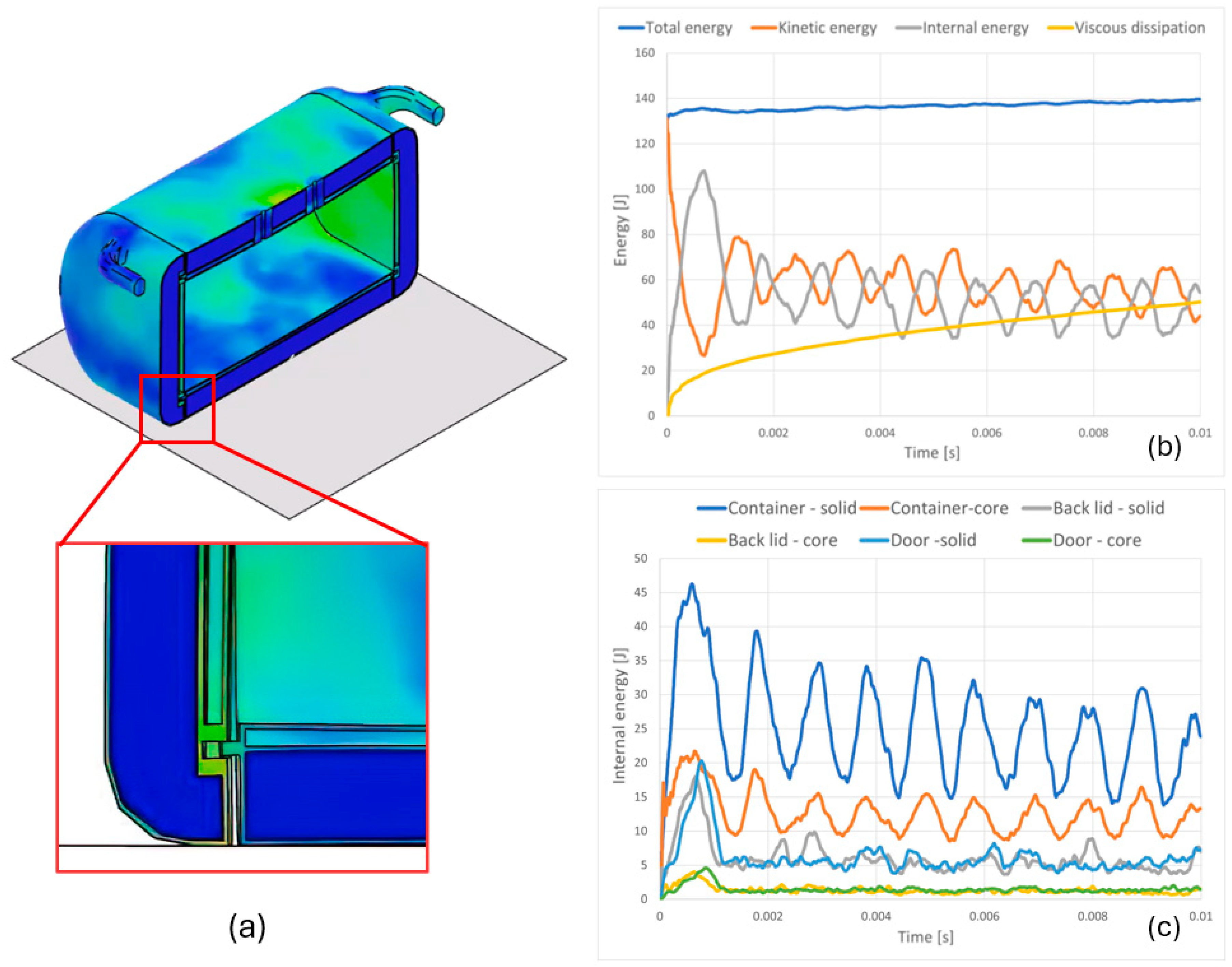
Cellular structures can be classified mainly into truss-based, shell-based, and plate-based types [15,17,18]. Their selection is non-trivial and considers both performance and manufacturability. Three-dimensional structures providing functional energy absorption and thermal insulation were considered [13,17]. Since the FFF ME process was selected, plate- and shell-based unit cells are evaluated considering their optimal manufacturability, in contrast to truss-based ones. For plate-based structures, an octet structure was modeled, as shown in Figure 8a. For the shell-based one, a triple periodic minimal surface (TPMS) gyroid was modeled, obtaining the shape from the equations:
sin X cos Y + sin Y cos Z + sin Z cos X = c
X = 2απx
Y = 2βπy
Z = 2γπz
where α, β, and γ are constants related to the unit cell size in the x, y, and z directions, respectively. The sandwich panels of lattice structures were obtained by repeating the unit cell in space, as shown in Figure 8b,c. The layers were 25 mm thick, with a top and bottom plate as boundaries, with a surface area of 75 mm × 75 mm. The finite element models were 2D meshes, where the top and bottom plates were shell sections with a thickness of 1.6 mm, while the lattice had a shell section with a thickness of 0.8 mm, equal to the dimensions of the FFF nozzle.
The material card used was created with non rate-dependent PETG properties reported using the Johnson–Cook plasticity model. The mechanical analyses of the lattice structures were performed. Concerning the boundary conditions, the simulations were conducted as an explicit dynamic step of 0.015 s with a translational velocity of the top plate of 1 m/s downwards. The bottom and top plates were fixedly constrained, leaving only the vertical translation of the top plate free. A general contact condition was set to avoid any unphysical penetration. The mechanical FEA was thus implemented to replicate the impact and the crumpling of the lattice structures. Figure 9a,b show the physical behavior of the sandwich panel model for octet and gyroid structures at 10% density, respectively. Figure 9c,d report the internal stress–strain curve and energy-displacement curve for octet and gyroid structures at 10% density, respectively. Tests at different densities evaluated the 10% gyroid structure as a promising lightweight and energy-absorption solution.
Physical panel models made of PETG were printed, as shown in Figure 10a, and experimental tests were performed using an Instron 6658 compression testing system equipped with a 30 kN load cell, as shown in Figure 10b. Physical compression tests allowed validation of the simulation setup, although analyzing the stress–strain curve of Figure 10c clearly showed reduced mechanical strength of the specimens, probably due to the lower characteristics of the actual printed material.
Regarding the material calibration, the stress–strain curve was imported, and calibration runs were performed using the root mean square error method, to obtain the equivalent constitutive material curve. The TPMS gyroid behaves and can be set as an orthotropic material, with uniform elastic moduli along the three orthotropy axes. Moreover, the equivalent material was applied to the compression of a 75 mm × 75 mm × 25 mm solid model simulated with an explicit dynamic analysis, providing identical results with much less computational effort.
Next, the thermal analysis of the lattice structure was performed. Concerning the boundary conditions, the bulk heat conduction coefficient, i.e., λs = 180 W/(mK), was applied to the structure and an initial temperature of the entire model was set to 4 °C. Then, a first static step of 1 s was performed to set a temperature of 50 °C on the top plate, while maintaining a fixed temperature of 4 °C on the bottom plate. Next, a second steady-state run of 5000 s was performed to achieve a steady heat flux. The thermal FEA was thus implemented to replicate a ΔT of 46 °C and the heat flux across of the lattice structures. This parameter was evaluated, finding an average value of Qavg = 202.41 W/m2. Figure 11 shows the temperature distribution and heat flux field within the domain of the 10% gyroid structure. The equivalent heat conduction coefficient determined by (2) is λeq = 0.110 W/(mK).
The outputs of the mesoscale design were (i) the tuned equivalent constitutive material for the overall structural simulation and (ii) the calculated equivalent conductivity coefficient for the overall thermal simulation, as shown in the model in Figure 3.

4.4. Validation

Comprehensive simulations were needed to validate the optimized layout of the functional container. The structural FEA was set up with equivalent materials assigned to each functional region, resulting in reduced computational costs. The PCM region was considered hollow, in favor of safety. Indeed, since the low-density infill of the final prototype will be the minimum for structural integrity according to feasibility of the FFF process, it may have a minimal structural role in case of impact. Conversely, the multifunctional lattice layer was considered as the core. Two ground impact conditions were analyzed, namely (i) the bottom side impact and (ii) the front side impact. In the analysis, the soil was modeled by a rigid plate with fixed DOFs, and the container impacts with an initial velocity of 15 m/s. Gravity was also taken into account. For the sake of conciseness, the results of the first analysis are reported. Figure 12a shows the leak-proof design. Figure 12b shows the total energy which remained almost stable during the process, while the kinetic energy was transformed into internal energy. Figure 12c shows the division of internal energies between different components, to study the effective work of each substructure. The maximum value of internal energy for the core was still low and corresponded to a quasi-elastic response, demonstrating the expected behavior of the lattice structure. However, most of the energy was absorbed due to the solid walls, so during the detailed design and preparation phase of the FFF construction, special attention was paid to maintaining a minimum external thickness.
Future work will focus on conducting experimental crash tests for the UAV. First, the impact conditions will be measured. The functional container will be equipped only with an additional high-sensitivity accelerometer capable of withstanding high-impact forces (e.g., at least ±200 g). The functional container will be dropped from a crane at different heights and initial angles onto a soft mat to reduce the number of prototypes to be replaced. This preliminary evaluation will provide insights into the velocity and acceleration during impact considering aerodynamic resistance in different conditions. Subsequently, to make the tests reproducible in terms of direction and velocity under controlled conditions, the functional container will be mounted on a rail system already used for car crash tests. A rigid crash barrier will simulate the most severe impact scenarios. To validate the leak-proof design, the functional container will be filled with liquid containing a colored or fluorescent dye to enhance leak visibility. Impact scenarios, including (i) bottom-side and (ii) front-side impacts, will be tested at speeds determined from the initial drop tests. Acceleration data will be analyzed to identify peak impact forces, while outside cameras will capture the deformation and damage process. The high-speed footage will be reviewed to correlate physical deformation with acceleration peaks. Structural failures will be examined, and the energy absorption capacity of the designed structure will be assessed. These crash tests will validate the structural FEA simulations and provide guidance for further structural improvements. The thermal FEA in the designed configuration determines a potential flight duration up to 2 h.
The detailed design followed the DfAM method, focusing on tuning the wall thicknesses of the functional regions and creating appropriate internal channels, to be printed without any support, for the correct filling of the PCM. In fact, the thicknesses were multiples of the nozzle sizes, ensuring three lines for the solid waterproof walls and only one line for the outer wall. Likewise, the thickness of the top and bottom layers, multiples of the layer height, ensured eight layers for the solid waterproof walls and only three for the outer wall. For each component, each functional region was exported to set the modifiers for the process settings. The FFF build preparation was performed via the open-source software OrcaSlicer V1.8.0 [46]. The PCM region was filled with 5% gyroid which is one of the lightest structures achievable by FFF. The final dimensions of the PCM region were updated to match the volume calculated by the simulations. The multifunctional lattice region was filled with the 10% gyroid as defined by the simulation. Additionally, to ensure a lightweight design, different densities were applied to non-functional regions, with high densities only being applied to structural parts, such as handles, insert housings, and bolted connections. Therefore, the global model and structural areas were set with 10% grid infill and 25% local thickening. Figure 13 and Figure 14 show the manufacturing simulation of the body and lid highlighting the subdivisions of the model regions.

4.5. Real Flight Test

The design of the functional container for the UAV was performed following the proposed DfAM method. The UAV was dimensioned and assembled seeking simplicity and durability. The functional container was printed in PETG, with a Kentstrapper (Kentstrapper Srl, Via Del Pollaiolo 130, 50142 Firenze, Italy) ZeroHS FFF ME machine, with 320 mm × 320 mm × 320 mm build volume. Moreover, the container was equipped with internal sensors to collect data on in-flight temperature and accelerations experienced by the content. The UAV, as shown in Figure 15a, was a demonstrator for emergency blood delivery in the city of Modena, having conducted a mission operating Beyond Visual Line Of Sight (BVLOS). Before take-off, the PCM in the container was initially conditioned at 2 °C and the blood bags were kept at 4 °C. The ambient air temperature was measured at 26 °C on average. The comparison of the temperatures monitored during the mission with the thermal simulation is reported in Figure 15b. The temperature increased slightly during the 3600 s mission, demonstrating the effectiveness of the PCM. In particular, the heat released during the phase change kept the temperature well between 4.2 °C and 5.2 °C. The actual temperature profile, showing an initial peak and an intermediate decrease, could be due to different initial temperatures between the PCM (2 °C), the blood bags (4 °C), and the internal air measured by the sensors. In fact, the external air was at 26 °C, and when the blood samples were introduced into the container, the air inside the container and that of the external environment mix and subsequently tended to heat up progressively.
Finally, the analysis of cell viability by flow cytometry verified that the biological samples were not altered during transport. The design specifications of thermal maintenance were met with an efficient use of materials since the total payload weight at take-off was only 5 kg. The crash protection specifications have not been validated experimentally yet, but only by simulation as reported in Section 4.3.

5. Conclusions

The present research focused on a DfAM method for the optimization of lattice structures for both thermal management and shock absorption. Lattice metamaterials are evolving, and multifunctionality represents a key direction [47]. The literature provides studies for thermal and vibrational design [48], structural and sound insulation design [49], energy absorption, and vibrational design [50], while the present research investigated and implemented thermal and energy absorption design. A systematic approach based on multi-scale design and driven by numerical simulations has been presented. The functional regions were organized and dimensioned at the macroscale, while the constituent lattice structures tailored to the container requirements were designed at the mesoscale. A case study on a container held by a UAV dedicated to transporting healthcare products and biological material has been presented. The main design objectives were to preserve the transported material by keeping it within a specific and narrow temperature range and to avoid any possible leakage of potentially infectious material in case of accident. The low-density functional lattice structures were filled with PCM that acted as a thermal battery. The multifunctional designed lattice structures aimed at the same time to (i) ensure the absorption of the kinetic energy of an impact and (ii) increase the thermal insulation of the casing. The non-functional regions were optimized between low-density and high-density, balancing respectively lightweight and structural requirements and providing efficient use of material. A BVLOS flight mission was performed as a demonstration of the urgent transport of blood bags. Blood samples were analyzed after the flight, showing no alteration in cell viability, demonstrating the effectiveness of the design achieved by the proposed method. The crash protection requirements were validated by simulation. The functional integration via AM and design of multifunctional lattice structures following the proposed DfAM approach could be used in future projects.
The present research paves the way for further investigations in electronics enclosures, automotive systems, and aerospace components. In particular, lattice structures offer potential as heat sinks and protective casings for reducing impact damage while efficiently managing thermal loads for batteries or sensors. In electric vehicles, lattice casings can effectively manage heat generation during operation and protect battery cells from road shocks. Their multifunctionality makes them ideal for use as heat sinks and mounting solutions for inverters and converters. The lightweight design of lattice structures is especially beneficial for enclosures that protect sensitive electronics in aerospace applications. Additionally, a promising application could be passive cooling systems for satellite components, where convective cooling is not viable in space environments.

Author Contributions

Conceptualization, E.D.; methodology, E.D. and M.P.; software, M.P.; validation E.D. and M.P.; writing—original draft preparation, E.D., M.P. and A.V.; writing—review and editing, E.D. and A.V.; supervision, A.V. and F.L. All authors have read and agreed to the published version of the manuscript.

Funding

This research was funded by Fondo Ateneo Ricerca (FAR) 2022 Mission Oriented—Prot. N. 0266371—26 October 2022.

Data Availability Statement

The data are available on request from the corresponding author.

Acknowledgments

The work was supported by the University of Modena and Reggio Emilia—Fondazione di Modena project “MO-UAS 4 LIFE: A NEW PERSPECTIVE IN LOCAL URGENT MEDICINE TRANSPORTATION”, funded by FAR 2022 Mission Oriented.

Conflicts of Interest

The authors declare no conflict of interest.

Appendix A

Main schemes and parameters of the MBD thermal analysis from Section 3.1 are reported hereafter.
The thermal analysis was based on heat balance of the different materials and regions of the model. The analysis started modeling the heat transfer rate for the internal air as shown in Figure A1a. The heat transfer rate between the PCM region and the external environment is represented in Figure A1b; the PCM region is modeled as a node of the electrical diagram, as shown in Figure A1c.
Figure A1. Lumped parameters schemes of (a) air heat balance, (b) heat transfer between the PCM region and the external environment, and (c) heat balance of the PCM region.
Jmmp 09 00024 g0a1
Integrating corresponding differential equations and imposing TP(0) based on the required mission, TP(t) can be found. Therefore, manipulating the equations, Ta(t) and Tbl(t) can be found.
Simulink implementation is discussed hereafter, and the parameters of the MBD analysis can be found in Figure A2.
The first subsystem was the internal air balance, which required as inputs the heat generated from the other subsystems and gave as output the temperature of the internal air, which was used in a feedback system in the other sub-models. The second subsystem was blood balance. The temperature of the air previously found was used as input to model the heat balance of the blood bags. The outputs were the heat generated or absorbed by the blood, and its temperature, which were used in the plot of the temperatures of the model. The last subsystem was the one of the PCM region. In this sub-model, the heat storage capacity of the material was represented. The main input was the internal air temperature, while the external environment temperature and the initial temperature of the PCM were inserted as parameters.
A subset of the model calculated the heat exchanged between the PCM region and the internal air, while another subset took into account the exchange with the external environment through the wall, considering the multifunctional lattice region. The last subset of the model replicated the PCM behavior, using a variable density between the solid and the liquid phase and the enthalpy for the current temperature of the material. This temperature was taken from a feedback loop, calculated from differential equations. Moreover, this temperature was sent to the temperature plot, like the air and the blood ones.
Figure A2. Simulink parameters and boundary conditions for the overall thermal simulation.
Jmmp 09 00024 g0a2

References

  1. Yang, S.; Zhao, Y.F. Additive manufacturing-enabled design theory and methodology: A critical review. Int. J. Adv. Manuf. Technol. 2015, 80, 327–342. [Google Scholar] [CrossRef]
  2. Thompson, M.; Moroni, G.; Vaneker, T.; Fadel, G.; Campbell, R.; Gibson, I.; Bernard, A.; Schulz, J.; Graf, P.; Ahuja, B.; et al. Design for additive manufacturing: Trends, opportunities, considerations, and constraints. CIRP Ann. Manuf. Technol. 2016, 65, 737–760. [Google Scholar] [CrossRef]
  3. Alfaify, A.; Saleh, M.; Abdullah, F.M.; Al-Ahmari, A.M. Design for additive manufacturing: A systematic review. Sustainability 2020, 12, 7936. [Google Scholar] [CrossRef]
  4. Vaneker, T.; Bernard, A.; Moroni, G.; Gibson, I.; Zhang, Y. Design for additive manufacturing: Framework and methodology. CIRP Ann. 2020, 69, 578–599. [Google Scholar] [CrossRef]
  5. Gibson, I.; Rosen, D.; Stucker, B. Additive Manufacturing Technologies: 3D Printing, Rapid Prototyping, and Direct Digital Manufacturing; Springer: New York, NY, USA, 2015. [Google Scholar] [CrossRef]
  6. Pradel, P.; Zhu, Z.; Bibb, R.; Moultrie, J. A framework for mapping design for additive manufacturing knowledge for industrial and product design. J. Eng. Des. 2018, 29, 291–326. [Google Scholar] [CrossRef]
  7. ISO 52910:2018; Additive Manufacturing—Design—Requirements, Guidelines and Recommendations. International Organization for Standardization: Geneva, Switzerland, 2018.
  8. Liu, J. Guidelines for AM part consolidation. Virtual Phys. Prototyp. 2016, 11, 133–141. [Google Scholar] [CrossRef]
  9. Plocher, J.; Panesar, A. Review on design and structural optimisation in additive manufacturing: Towards next-generation lightweight structures. Mater. Des. 2019, 183, 108164. [Google Scholar] [CrossRef]
  10. Durakovic, B. Design for additive manufacturing: Benefits, trends and challenges. Period. Eng. Nat. Sci. 2018, 6, 179–191. [Google Scholar] [CrossRef]
  11. Obi, M.U.; Pradel, P.; Sinclair, M.; Bibb, R. A bibliometric analysis of research in design for additive manufacturing. Rapid Prototyp. J. 2022, 28, 967–987. [Google Scholar] [CrossRef]
  12. Fuchs, D.; Bartz, R.; Kuschmitz, S.; Vietor, T. Necessary advances in computer-aided design to leverage on additive manufacturing design freedom. Int. J. Interact. Des. Manuf. 2022, 16, 1633–1651. [Google Scholar] [CrossRef]
  13. Grabowska, B.; Kasperski, J. The Thermal Conductivity of 3D Printed Plastic Insulation Materials—The Effect of Optimizing the Regular Structure of Closures. Materials 2020, 13, 4400. [Google Scholar] [CrossRef]
  14. Alqahtani, S.; Ali, H.M.; Farukh, F.; Silberschmidt, V.V.; Kandan, K. Thermal performance of additively manufactured polymer lattices. J. Build. Eng. 2021, 39, 102243. [Google Scholar] [CrossRef]
  15. Maconachie, T.; Leary, M.; Lozanovski, B.; Zhang, X.; Qian, M.; Faruque, O.; Brandt, M. SLM lattice structures: Properties, performance, applications and challenges. Mater. Des. 2019, 183, 108137. [Google Scholar] [CrossRef]
  16. Zhong, H.; Song, T.; Li, C.; Das, R.; Gu, J.; Qian, M. The Gibson-Ashby model for additively manufactured metal lattice materials: Its theoretical basis, limitations and new insights from remedies. Curr. Opin. Solid State Mater. Sci. 2023, 27, 101081. [Google Scholar] [CrossRef]
  17. Yin, H.; Zhang, W.; Zhu, L.; Meng, F.; Liu, J.; Wen, G. Review on lattice structures for energy absorption properties. Compos. Struct. 2023, 304, 116397. [Google Scholar] [CrossRef]
  18. Lu, C.; Hsieh, M.; Huang, Z.; Zhang, C.; Lin, Y.; Shen, Q.; Chen, F.; Zhang, L. Architectural Design and Additive Manufacturing of Mechanical Metamaterials: A Review. Engineering 2022, 17, 44–63. [Google Scholar] [CrossRef]
  19. Dong, G.; Tang, Y.; Li, D.; Zhao, Y.F. Design and optimization of solid lattice hybrid structures fabricated by additive manufacturing. Addit. Manuf. 2020, 33, 101116. [Google Scholar] [CrossRef]
  20. Tang, Y.; Zhao, Y.F. A survey of the design methods for additive manufacturing to improve functional performance. Rapid Prototyp. J. 2016, 22, 569–590. [Google Scholar] [CrossRef]
  21. Tamburrino, F.; Graziosi, S.; Bordegoni, M. The Design Process of Additively Manufactured Mesoscale Lattice Structures: A Review. ASME J. Comput. Inf. Sci. Eng. 2018, 18, 040801. [Google Scholar] [CrossRef]
  22. Cheng, L.; Bai, J.; To, A.C. Functionally graded lattice structure topology optimization for the design of additive manufactured components with stress constraints. Comput. Methods Appl. Mech. Eng. 2019, 344, 334–359. [Google Scholar] [CrossRef]
  23. Wang, C.; Gu, X.; Zhu, J.; Zhou, H.; Li, S.; Zhang, W. Concurrent design of hierarchical structures with three-dimensional parameterized lattice microstructures for additive manufacturing. Struct. Multidiscip. Optim. 2020, 61, 869–894. [Google Scholar] [CrossRef]
  24. Kim, J.E.; Park, K. Multiscale Topology Optimization Combining Density-Based Optimization and Lattice Enhancement for Additive Manufacturing. Int. J. Precis. Eng. Manuf.-Green Technol. 2021, 8, 1197–1208. [Google Scholar] [CrossRef]
  25. Li, S.; Xin, Y.; Yu, Y.; Wang, Y. Design for additive manufacturing from a force-flow perspective. Mater. Des. 2021, 204, 109664. [Google Scholar] [CrossRef]
  26. Pahl, G.; Beitz, W.; Feldhuesen, J.; Grote, K.H. Engineering Design: A Systematic Approach; Springer: London, UK, 2007; Volume 34. [Google Scholar] [CrossRef]
  27. VDI. VDI 2221. Systematic Approach to the Development and Design of Technical Systems and Products; VDI: Berlin, Germany, 1993. [Google Scholar]
  28. Tomiyama, T.; Gu, P.; Jin, Y.; Lutters, D.; Kind, C.; Kimura, F. Design methodologies: Industrial and educational applications. CIRP Ann.—Manuf. Technol. 2009, 58, 543–565. [Google Scholar] [CrossRef]
  29. Schmitt, P.; Zorn, S.; Gericke, K. Additive manufacturing research landscape: A literature review. Proc. Des. Soc. 2021, 1, 333–344. [Google Scholar] [CrossRef]
  30. Bourell, D.L.; Leu, M.C.; Rosen, D.W. Roadmap for Additive Manufacturing Identifying the Future of Freeform Processing; University of Texas for Freeform Fabrication Advanced Manufacturing Center: Austin, TX, USA, 2009. [Google Scholar]
  31. Kumke, M.; Watschke, H.; Vietor, T. A newmethodological framework for design for additive manufacturing. Virtual Phys. Prototyp. 2016, 11, 3–19. [Google Scholar] [CrossRef]
  32. Wiberg, A.; Persson, J.; Ölvander, J. Design for additive manufacturing—A review of available design methods and software. Rapid Prototyp. J. 2019, 25, 1080–1094. [Google Scholar] [CrossRef]
  33. Lopez, L.; Maury, H.; Pacheco, J. Design for additive manufacturing: A comprehensive review of the tendencies and limitations of methodologies. Rapid Prototyp. J. 2021, 27, 918–966. [Google Scholar] [CrossRef]
  34. Egan, P.F. Design for Additive Manufacturing: Recent Innovations and Future Directions. Designs 2023, 7, 83. [Google Scholar] [CrossRef]
  35. Alam, M.; Singh, H.; Limbachiya, M.C. Vacuum Insulation Panels (VIPs) for building construction industry—A review of the contemporary developments and future directions. Appl. Energy 2011, 88, 3592–3602. [Google Scholar] [CrossRef]
  36. Damiani, L.; Revetria, R.; Morra, E.; Giribone, P. A Smart Box for Blood Bags Transport: Simulation Model of the Cooling Autonomy Control System. Adv. Sci. Technol. Eng. Syst. J. 2020, 5, 249–255. [Google Scholar] [CrossRef]
  37. du Plessis, A.; Broeckhoven, C.; Yadroitsava, I.; Yadroitsev, I.; Hands, C.H.; Kunju, R.; Bhate, D. Beautiful and Functional: A Review of Biomimetic Design in Additive Manufacturing. Addit. Manuf. 2019, 27, 408–427. [Google Scholar] [CrossRef]
  38. Nath, S.D.; Nilufar, S. An overview of additive manufacturing of polymers and associated composites. Polymers 2020, 12, 2719. [Google Scholar] [CrossRef] [PubMed]
  39. Islam, M.A.; Mobarak, M.H.; Rimon, M.I.H.; Al Mahmud, M.Z.; Ghosh, J.; Ahmed, M.M.S.; Hossain, N. Additive manufacturing in polymer research: Advances, synthesis, and applications. Polym. Test. 2024, 132, 108364. [Google Scholar] [CrossRef]
  40. Palanisamy, C.; Raman, R.; Dhanraj, P.K. Additive manufacturing: A review on mechanical properties of polyjet and FDM printed parts. Polym. Bull. 2022, 79, 7065–7116. [Google Scholar] [CrossRef]
  41. Saleh Alghamdi, S.; John, S.; Roy Choudhury, N.; Dutta, N.K. Additive Manufacturing of Polymer Materials: Progress, Promise and Challenges. Polymers 2021, 13, 753. [Google Scholar] [CrossRef]
  42. Shanmugam, V.; Babu, K.; Kannan, G.; Mensah, R.A.; Samantaray, S.K.; Das, O. The thermal properties of FDM printed polymeric materials: A review. Polym. Degrad. Stab. 2024, 228, 110902. [Google Scholar] [CrossRef]
  43. Gorguluarslan, R.M.; Gungor, O.U.; Yıldız, S.; Erem, E. Energy absorption behavior of stiffness optimized graded lattice structures fabricated by material extrusion. Meccanica 2021, 56, 2825–2841. [Google Scholar] [CrossRef]
  44. Chamini, R.; Shanqing, X.; Yvonne, D.; Darren, F.; Dong, R. Quasi-static and dynamic compression of additively manufactured functionally graded lattices: Experiments and simulations. Eng. Struct. 2023, 284, 115909. [Google Scholar] [CrossRef]
  45. Dalpadulo, E.; Vergnano, A.; Leali, F. Urban Air Mobility for Medical Delivery: An Innovative Approach to Healthcare Logistics. In Proceedings of the ADM 2024, Palermo, Italy, 11–13 September 2024. Lecture Notes in Mechanical Engineering, 2024. [Google Scholar]
  46. Orca Slicer—3D printing Slicer. Available online: https://orcaslicer.net/about/ (accessed on 1 December 2024).
  47. Jia, Z.; Liu, F.; Jiang, X.; Wang, L. Engineering lattice metamaterials for extreme property, programmability, and multifunctionality. J. Appl. Phys. 2020, 127, 150901. [Google Scholar] [CrossRef]
  48. Babatola, O.; Patil, G.; Hsieh, D.; Matlack, K.; Sinha, S. Independently Tunable Thermal Conductance and Phononic Band Gaps of 3D Lattice Materials. Adv. Eng. Mater. 2019, 22, 1901004. [Google Scholar] [CrossRef]
  49. Li, X.; Zhao, M.; Yu, X.; Chua, J.W.; Yang, Y.; Lim, K.M.; Zhai, W. Multifunctional and customizable lattice structures for simultaneous sound insulation and structural applications. Mater. Des. 2023, 234, 112354. [Google Scholar] [CrossRef]
  50. Ye, H.; Shen, W.; Wang, W.; Tao, R. A systematic design of multifunctional lattice structures with energy absorption and phononic bandgap by topology and parameter optimization. Int. J. Smart Nano Mater. 2023, 14, 265–285. [Google Scholar] [CrossRef]
Figure 1. Design method for functional integration at macro- and meso- scale levels.
Jmmp 09 00024 g001
Figure 2. Conceptual layout of the functional container with multi-layer walls.
Jmmp 09 00024 g002
Figure 3. Thermal model of the functional container with (a) lumped parameters and (b) Matlab-Simulink blocks.
Jmmp 09 00024 g003
Figure 4. Sandwich panel model representing the outer layer of multifunctional lattice for mesoscale design.
Jmmp 09 00024 g004
Figure 5. Dimensional constraints of the UAV payload in (a) front and (b) side views.
Jmmp 09 00024 g005
Figure 6. Macroscale design: functional regions of door, body, and lid, from left to right.
Jmmp 09 00024 g006
Figure 7. Results of the overall thermal simulation for (a) macroscale design and (b) final validation after implementing the multifunctional region mesoscale design.
Jmmp 09 00024 g007
Figure 8. Mesoscale design with (a) plate-based and surface-based unit cells design, (b) plate-based lattice panel model and mesh, and (c) surface-based lattice panel model and mesh.
Jmmp 09 00024 g008
Figure 9. Qualitative compressive structural behavior of (a) 10% gyroid and (b) octet lattice panel models, resulting in (c) stress–strain curve and (d) and internal energy-displacement curve of the lattice mechanical analysis.
Jmmp 09 00024 g009
Figure 10. Structural validation experiment: (a) 3D printing of the panel model; (b) panel model before and after the compression test; (c) comparison between experimental and simulated strain–stress curves.
Jmmp 09 00024 g010
Figure 11. Thermal analysis results of (a) temperature and (b) heat flux of 10% gyroid lattice panel model.
Jmmp 09 00024 g011
Figure 12. Results of impact simulation of the bottom side: (a) structural validation of the functional container, (b) energy plot of the whole model, and (c) internal energy of the different components.
Jmmp 09 00024 g012
Figure 13. FFF process simulation of the body.
Jmmp 09 00024 g013
Figure 14. FFF process simulation of the lid.
Jmmp 09 00024 g014
Figure 15. Validation mission with (a) functional container held by the UAV and (b) comparison between the monitored and simulated temperatures.
Jmmp 09 00024 g015
Table 1. Properties of AM polymers, source: Ansys GRANTA 2021 database, except for cost (investigation of 3D printing materials available on the market).
MaterialDensity
ρ (kg/m3)
Specific Strength
Ys (kN·m/kg)
Toughness
G (kJ/m2)
Thermal
Conductivity
λ (W/m·°C)
Glass
Temperature
TG (°C)
Cost
(EUR/kg)
PLA (tough)1.22–1.25 × 10330.7–48.62.21–3.670.13–0.1752–6020
PETG1.26–1.28 × 10337.7–41.72.18–3.10.257–0.26781–9122.5
ABS1.02–1.08 × 10328.2–42.11.35–2.040.226–0.23588–12040
PA1–1.02 × 10334.4–438.01–10.70.218–0.30640–4345
PEEK1.3–1.32 × 10368.7–842.02–4.60.24–0.26143–157720
PEI1.26–1.28 × 10357.9–63.91.46–50.123–0.13215–217300
Table 2. Workflow of phases and main results in the systematic design.
Problem DefinitionConceptual DesignEmbodiment Design
Thermal maintenance—insulationInsulating materials and/or
lattice structure.
Selection of polymers with low thermal conductivity. Design at mesoscale: lattice structure for improved thermal insulation.
Thermal maintenance—conditioningActive cooling systems
powered with electric energy or passive systems based on PCM walls of the container.
Design at macroscale: regions of lattice structure filled with PCM.
Crash protectionRobust structure made of a high-strength material or sacrificial impact attenuators or
lattice structure.
Selection of polymers with high strength and toughness. Design at the macroscale for impact and at the mesoscale for lattice structure shock absorption.
LightweightingCellular or porous structures from nature.Optimization of the geometries of the lattice structures, with high-density and low-density regions.
Disclaimer/Publisher’s Note: The statements, opinions and data contained in all publications are solely those of the individual author(s) and contributor(s) and not of MDPI and/or the editor(s). MDPI and/or the editor(s) disclaim responsibility for any injury to people or property resulting from any ideas, methods, instructions or products referred to in the content.

