Review

Adaptive Aberration Correction for Laser Processes Improvement

Department of Mathematical and Computational Sciences, Physics Science and Earth Science, University of Messina, Viale F. Stagno D’Alcontres 31, I-98166 Messina, Italy
*
Author to whom correspondence should be addressed.
J. Manuf. Mater. Process. 2025, 9(4), 105; https://doi.org/10.3390/jmmp9040105
Submission received: 21 February 2025 / Revised: 20 March 2025 / Accepted: 21 March 2025 / Published: 23 March 2025
(This article belongs to the Special Issue Advances in Laser-Assisted Manufacturing Techniques)

Abstract

:
The ultrafast laser processing of three-dimensional structures characterized by highly spatially resolved features is more efficiently realized by implementing adaptive optics. Adaptive optics allow for the correction of optical aberrations, introduced when focusing inside the machined material, by tailoring the focal intensity distribution for the specific texturing task, in a reduced processing time. The aberration corrections by adaptive optics allow for a simplified scan strategy for the selective laser micromachining of transparent materials using depth-independent processing parameters, overcoming the limits related to the previously necessary pulse energy adjustment for different z positions in the material volume. In this paper, recent developments in this field are presented and discussed, mainly focusing on the use of dynamic optical elements—deformable mirrors and liquid crystal spatial light modulators—to obtain a high degree of laser processing control by an in-time correction of optical aberrations on different workpieces and mainly of transparent materials.

1. Introduction

Ultrafast lasers utilize extremely short pulses (tens to hundreds of femtoseconds) that allow for high precision in material processing. The rapid energy absorption minimizes thermal effects, leading to reduced heat-affected zones (HAZs) and enabling the creation of intricate 3D features. However, the effectiveness of this process can be significantly hindered by optical aberrations, which distort the laser focus over varying depths within a material. Thus, the efficiency and accuracy of the machining process require the optimization of the laser beam profile to ensure precise focal placement. The implementation of adaptive optics (AO) has demonstrated significant improvements in the fidelity of laser-written structures, particularly in complex materials such as diamond and silica. This includes the real-time correction of the disturbed wavefronts, which also reduces the cost of power supply necessary for processing the material due to the defocus of the laser beam. This is mainly performed by manipulating the spatial distribution of light energy for structured and wide-area fabrication, and by modulating the phase, amplitude and/or polarization of the laser beam [1]. The integration of adaptive optics with ultrafast laser technology is poised to revolutionize three-dimensional fabrication. As research continues to explore new adaptive elements and configurations, the potential for creating even more intricate and functional microstructures expands. This synergy not only enhances existing applications but also opens doors for innovative uses in fields such as integrated optics and lab-on-a-chip technologies.
This work reviews recent advances in this field, with a particular emphasis on using dynamic optical elements—adaptive optics—to achieve precise control over laser processing. First, we report some information about AO technologies, their configurations as well as the core principle of AO, which involves measuring distortions and applying corrective measures to restore the wavefront to its ideal shape. Subsequently, we report the main concepts regarding the integration of AO into wavefront shaping systems. We have outlined the significant advancement in high-power laser applications, offering improved precision, efficiency, and versatility essential for modern technological demands.
However, challenges such as improving robustness and reliability still remain critical for unlocking the full potential of AO technologies. Ultimately, this review aims to provide guidelines to analyze potential technological innovations that could further extend the capabilities of AO in industrial or scientific applications (e.g., to optimize the extreme parallelization of laser beams to increase processing speed), stimulating new ideas on how to exploit AO in yet-unexplored contexts (e.g., improving energy efficiency in AO-enabled laser processes) by taking into account the environmental impact.

2. Adaptive Optical Technologies

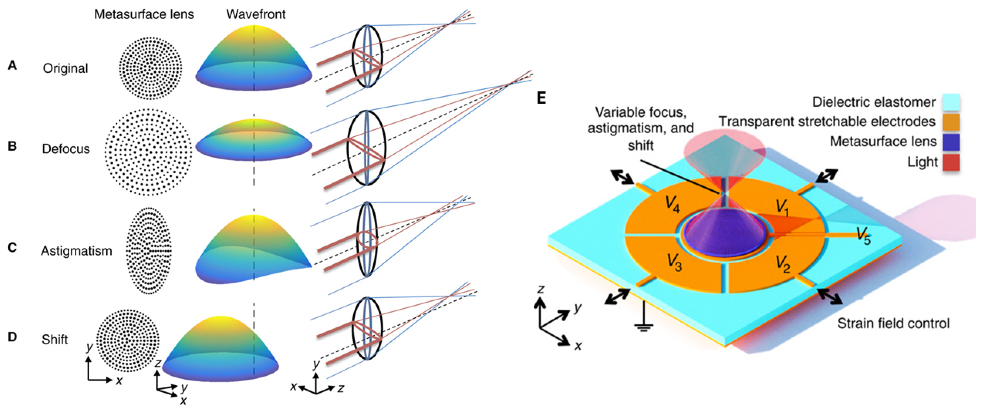
Aberrations affect the quality and accuracy of an optical system, reducing the images’ resolution and contrast. As reported extensively in Appendix A, in geometrical optics, aberrations arise when light rays deviate from their ideal path due to lens shape and alignment. The wavefront approach describes these aberrations in terms of wavefront shapes, where deviations from a perfect wavefront indicate the presence of aberrations. The order of geometrical aberration corresponds to the symmetry of wave aberration, with the latter geometry being one order higher. The definition of geometrical aberration is the deviation of a real imaging point from the ideal one. Using the power-series polynomial representation, the geometrical aberration order is given by the sum of the order of the angle and distance between the beam and the optical axis. Instead, the order of the wave aberration is obtained by adding the value 1 to the geometrical aberration order. For instance, the two-fold astigmatism is represented by the first- and second-order aberration in terms of the geometrical and wave aberrations, respectively. Some approaches are used to compensate or reduce aberration effects. One of these methods adopt multiple optical elements in combination, such as achromatic and apochromatic lenses or aspherical and toroidal mirrors [2]. Sawant et al. [3] suggest the use of hybrid components, combining the optical power of a refractive and a diffractive optical system, to realize compact doublet lenses that correct various aberrations. Figure 1 shows the scheme of the hybrid lens-metacorrector and the theoretical and experimental results obtained, showing that the overall device efficiency of the fabricated metasurface is around 10–25% in the wavelength range of 600 to 800 nm.

2.1. Adaptive Optics: Key Developments and Their Impact

Recently, adaptive optics (AO) is largely implemented for multiphoton, stimulated emission depletion and selective plane illumination microscopies, offering a significant improvement in resolution over conventional light microscopy approaches [4,5,6,7]. AO concept was first proposed by Horace W. Babcock in 1953, aiming to improve astronomical imaging by using a deformable mirror to correct wavefront errors in real-time. The initial applications were primarily military, driven by the need for clear images of satellites during the Cold War, which led to significant advancements in the technology. In the late 20th century, particularly during the 1990s, advances in computer technology made AO systems more practical and widespread [8]. This period saw the introduction of laser guide stars, which created artificial points of light in the atmosphere to measure distortions more effectively, allowing astronomers to observe fainter celestial objects [9].
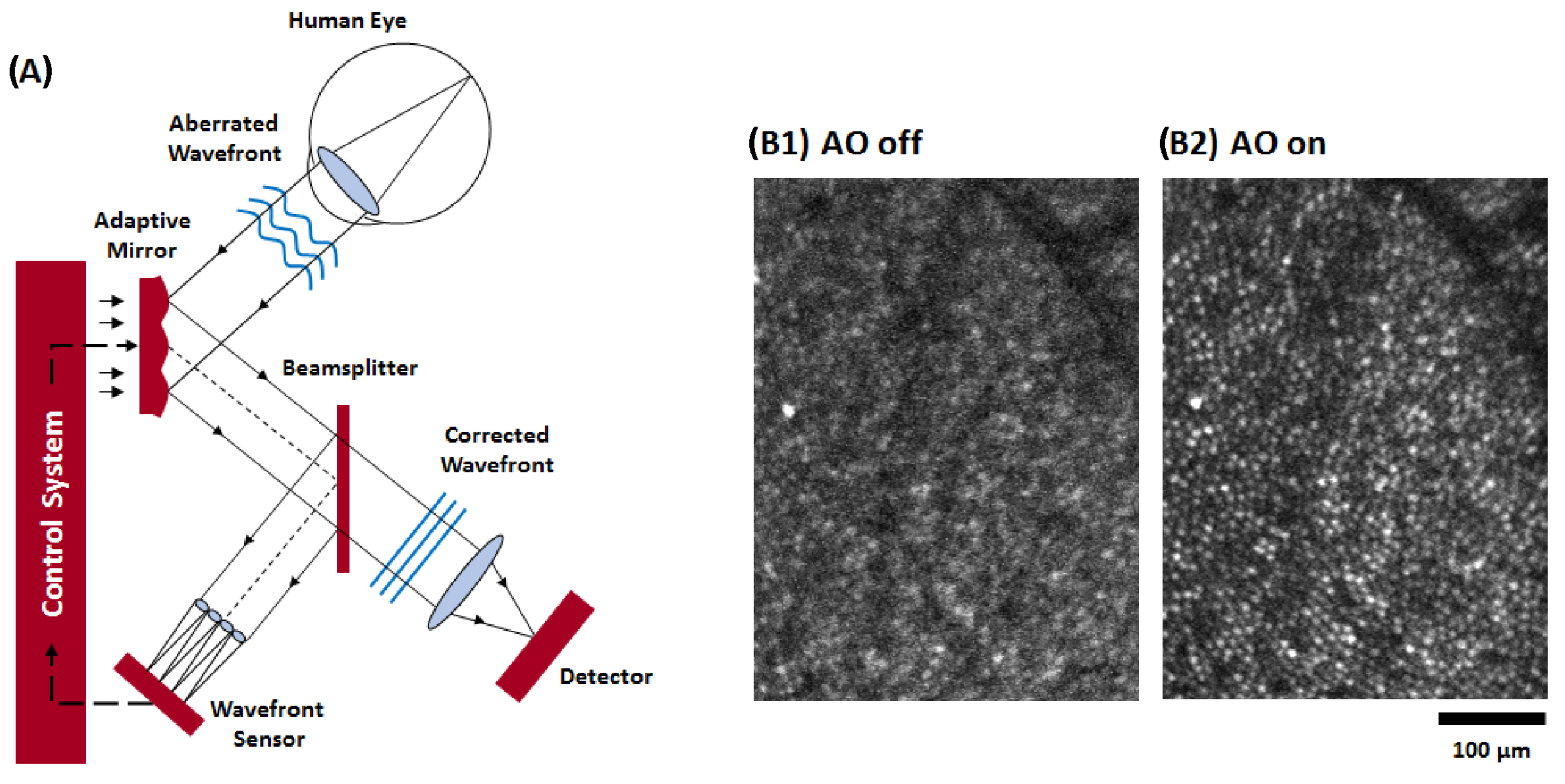
The application of AO to ophthalmology began in the late 1990s, with pioneering work by researchers such as David R. Williams at the University of Rochester. This initial research demonstrated the potential of AO to correct ocular aberrations, allowing for high-resolution imaging of the retina and its cellular structures, which were previously only observable through histological techniques [10,11,12]. AO ophthalmoscopy allows us to visualize cellular-sized structures within the living human retina, such as photoreceptors, nerve fibers and capillaries (see Figure 2).
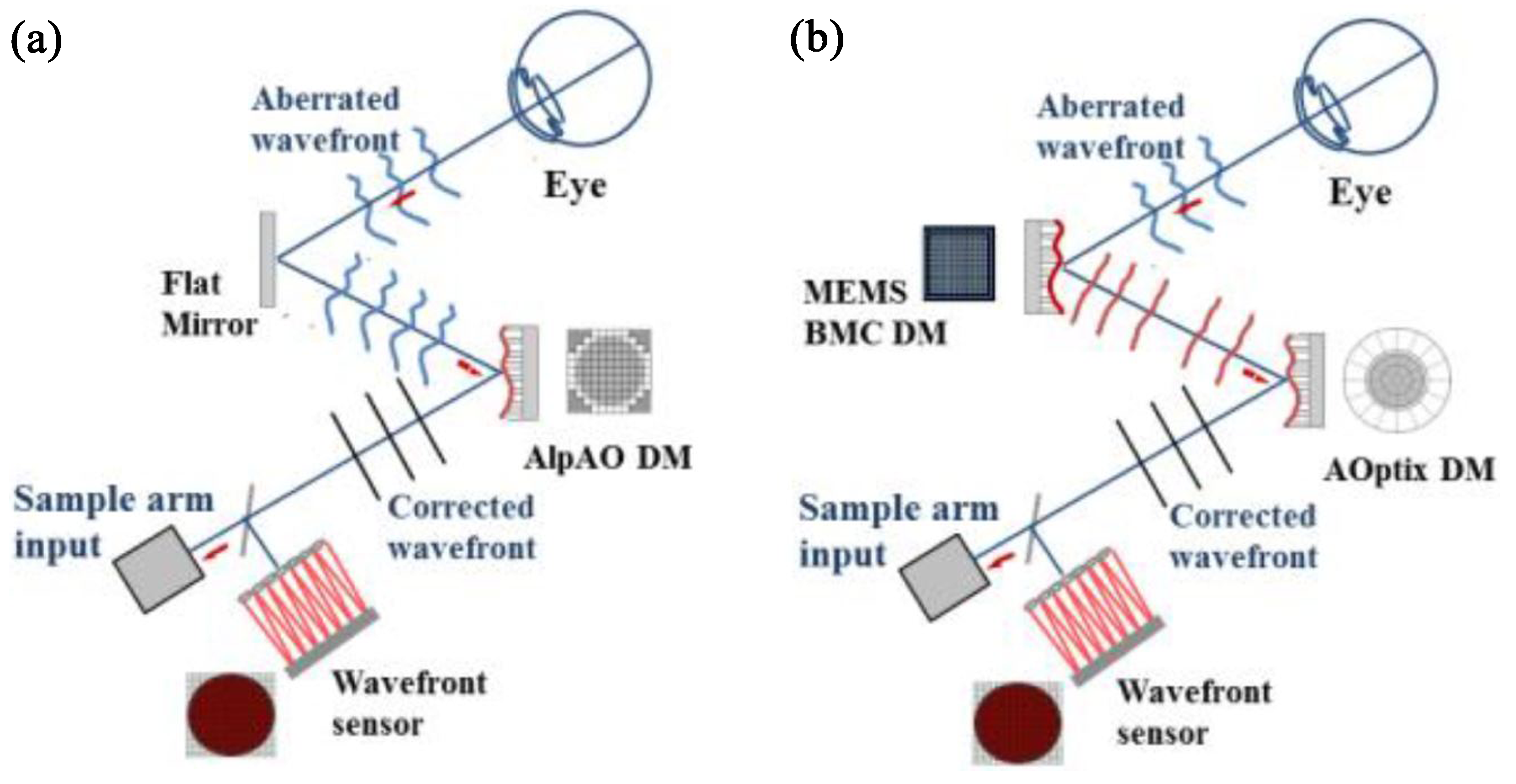
A detailed review regarding the optical wavefront technologies used to improve patient quality of vision and meet clinical requests has already been written by the authors (see ref. [13]). AO clinical applications are nowadays expanding. Among the current uses, they include (i) assessing retinal diseases where traditional imaging falls short, such as identifying lesions undetectable by standard fundus exams; (ii) developing objective visual function tests that monitor both photoreceptors and retinal vasculature, potentially aiding in managing ocular and systemic vascular diseases; and (iii) supporting gene therapy trials by providing detailed insights into cellular structures affected by genetic disorders. Thus, the ability to visualize individual cells and quantify cell loss has significant implications for early diagnosis and treatment planning [14]. On the other hand, the development of ultrafast AO systems has marked a significant leap forward. These systems can correct dynamic aberrations at much higher frequencies (up to 30 times faster than previous systems), improving imaging performance under clinically relevant conditions [15]. This advancement enhances the ability to capture high-resolution images even during normal eye movements [16]. The implementation of microelectromechanical systems (MEMSs) contributed significantly to the development of smaller and cost-effective AO systems [17] by enabling high-resolution wavefront correction. As an example, Figure 3 shows two AO systems with the same elements but using one (Figure 3a) or two (Figure 3b) different types of deformable mirrors (DMs). In the first case, a flat mirror was used in combination with an AlpAO DM with 69 actuators [18]; in the other case, an AOptix bimorph deformable mirror with 35 actuators, for low- and high-stroke correction, was used together with a Boston Micromachines MEMS DM (140 actuators) for high-order correction [19].
In vision science, MEMS technology has facilitated the development of scanning laser ophthalmoscopes that utilize adaptive optics to enhance retinal imaging quality. Various control algorithms have been compared to optimize the performance of these systems, demonstrating that MEMS DMs can effectively suppress wavefront errors and improve image quality [20]. Despite the great advantages of AO applications, AO imaging typically requires more time compared to conventional methods. The process of scanning patients can be lengthy, making it challenging to incorporate AO into routine clinical workflows, especially in busy practice settings. Moreover, AO systems often image only a small area of the retina at a time. This limitation can make it difficult to assess larger retinal regions or to conduct comprehensive examinations without multiple scans, which further extends the time required for each patient visit [10]. Furthermore, current AO systems may struggle with dynamic aberrations and require faster correction capabilities to accommodate real-world clinical scenarios where eye movement and other factors can introduce additional distortions [16,21]. Hence, ensuring robust performance under various conditions remains a challenge.

2.2. How Adaptive Optical Systems Work: Components and Principles

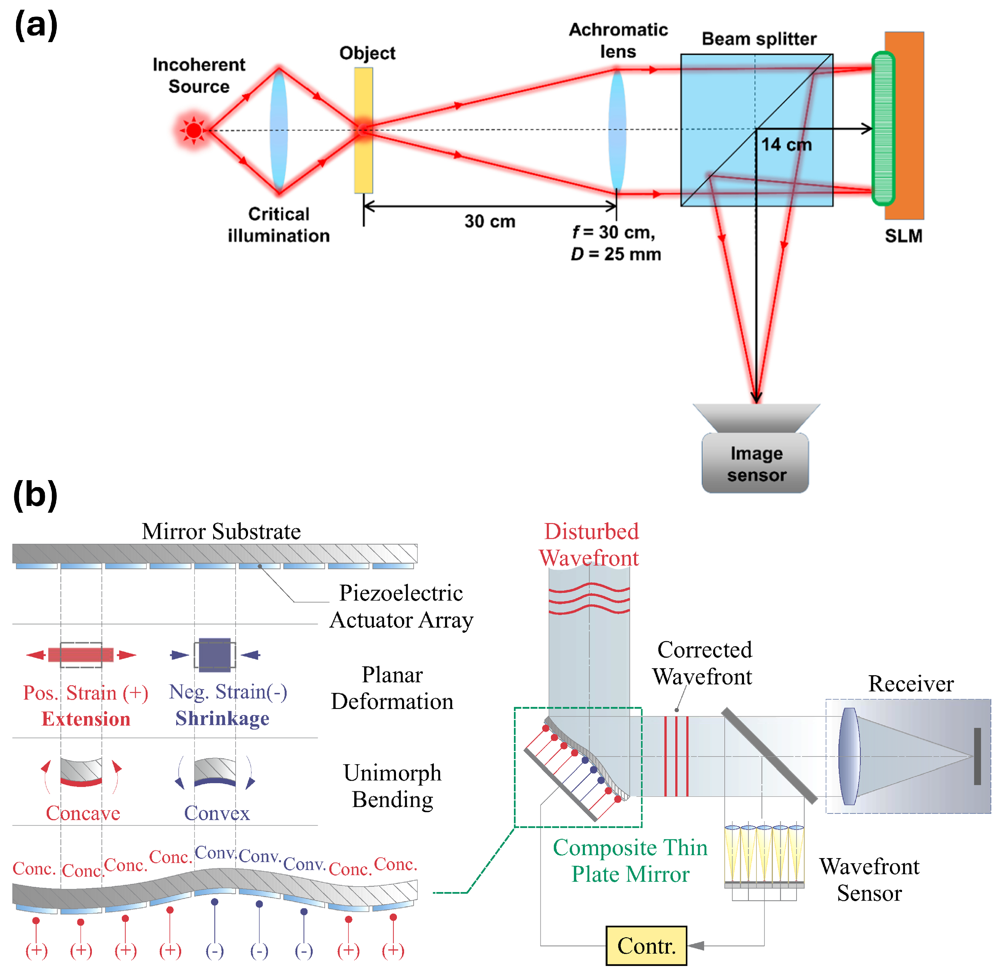
AO principle is based on the change in shape or position in response to the aberrations detected by a sensor, which analyzes the wavefront of the light, allowing to correct the aberrations in real-time [22]. Critical components in modern optical systems, particularly in adaptive optics applications, are the slit illumination and the deformable mirrors which play crucial roles in compensating wavefront aberrations. Slit illumination control optimizes light distribution across the aperture. By controlling the illumination profile, it improves the signal-to-noise ratio in wavefront sensing, leading to more accurate measurements of wavefront distortions. Consequently, this allows for more effective adjustments using adaptive optics components, resulting in better overall image quality and performance in optical systems. Improved spatial resolution and dynamic range can be achieved by employing pyramid wavefront sensors and by using phase diversity methods. Instead, real-time increased sensitivity and reduced latency were obtained with high-speed cameras and spatial light modulators (SLMs). These latter modulate the amplitude, phase and polarization of an incident light beam thanks to their quasiplanar geometry (see Figure 4).
Deformable mirrors are fundamental adaptive optics elements that can dynamically correct optical aberrations. Working principles of the Shack–Hartmann sensor (S-H), SLMs and of deformable mirror (DM) are extensively described in ref. [13]. Here, we report only a schematic representation of S-H and pyramid sensors in Figure 5 as well as of SLM and DM in Figure 6 together with a brief description.
Deformable mirrors (DMs) correct wavefront aberrations by dynamically adjusting their reflective surface shape, thereby ensuring that the light converges accurately to form a circular cross-section in the focal intensity distribution. This is achieved through numerous actuators that deform the mirror to create a wavefront that is the negative of the aberrations encountered. As light reflects off the DM, it compensates for distortions, thus restoring the focus to an optimal circular cross-section. For example, a hybrid DM can employ piezoelectric and magnetostrictive materials to manipulate its reflective surface, correcting both lower- and higher-order Zernike modes, which is crucial for maintaining a circular intensity distribution. This adaptability enables the transformation of Gaussian beams into desired shapes while preserving spatial characteristics.
Near-diffraction limited fabrications (at nominal depths of up to 50 μ m) were reached by combining SLM and DM, allowing for a net increment of about 10 μ m achievable depth without aberration correction: the unaberrated focal spot dimensions were maintained and the laser power was reduced [29,30]. For laser beam-shaping applications, Kuang et al. [31] realized parallel laser micro-structures using the synchronization of SLM and computer-generated holograms (CGHs). The same goal was reached using two adaptive mirrors to independently control the focus diameter and the focus position of the laser beam in cutting, welding and scanning systems [32].

2.3. Adaptive Optics Systems: Common Architectures

Adaptive optics configurations vary widely in complexity and application, from simple single-conjugated systems to sophisticated multi-conjugated setups. The choice of configuration depends on specific requirements such as the nature of distortions, the desired imaging quality, and budget constraints. Each system plays a vital role in enhancing optical performance across various fields, including astronomy, laser processing, and biomedical imaging. An adaptive optics system typically consists of three main components:
  • Wavefront sensors: These devices measure the aberrations in the incoming light wavefront. They can be either direct sensors or sensorless systems that infer distortions from image quality.
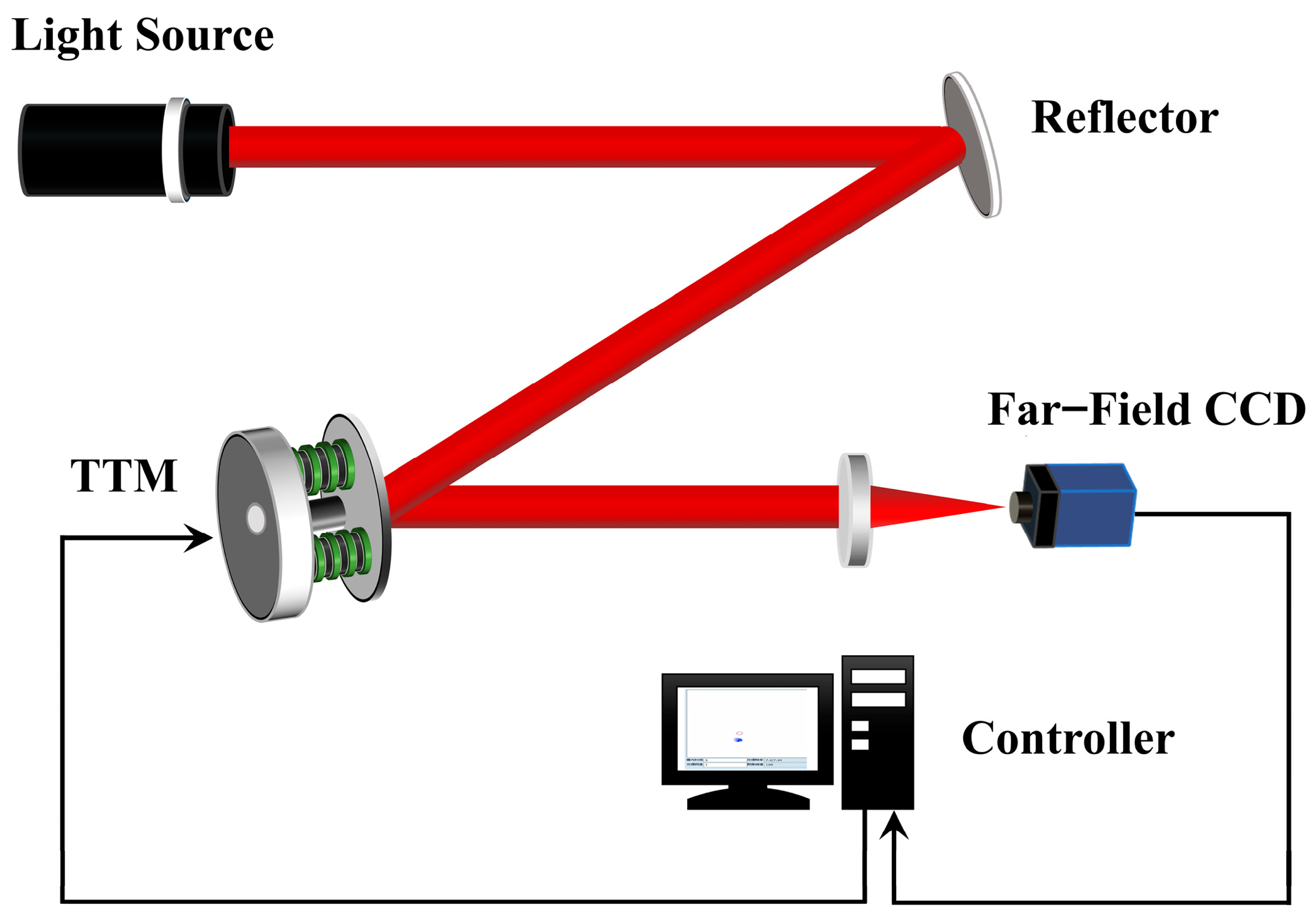
  • Tip-tilt mirror (TTM): TTM corrects the tilts of the incoming wavefronts in two dimensions. It achieves this by making small rotations around two axes, effectively realigning the light path to reduce distortion. The TTM is typically placed in front of the wavefront sensor. This configuration allows for a closed system, where the sensor continuously measures wavefront distortions and sends corrective signals to the TTM [33] (Figure 7).
    The TTM is particularly effective at correcting low-order aberrations (such as tilt and defocus), which account for a significant portion of the distortion caused by atmospheric conditions. By addressing these errors first, higher-order aberrations can then be corrected using more complex deformable mirrors.
  • Deformable Mirrors (DMs): DMs are critical components that adjust their shape in real-time to compensate for detected aberrations. They can have varying numbers of actuators, allowing for precise control over the wavefront correction [34]. Recent advancements include the development of liquid crystal spatial light modulators and MEMS-based deformable mirrors (Figure 8).
    These latter mirrors consist of a flexible membrane supported by an array of actuators that can adjust the mirror’s shape in real-time to correct for wavefront distortions caused by atmospheric turbulence or optical imperfections. For instance, an MEMS DM with 489 actuators has been shown to effectively generate individual Zernike polynomials, which are essential for correcting aberrations [35].
  • Control Algorithms: Algorithms, such as hill-climbing or other feedback mechanisms, optimize the adjustments made by the DMs to enhance image quality.
As extensively reported in ref. [1], several reconfigurable optical elements act to modify the beam profile. Salter and Booth also report several examples of laser processing to generate chiral surface, nanostructures, 3D nanoarray, etc., outlining the benefits of using AO technologies. These components can be configured in either an open-loop or closed-loop system. In an open-loop system, the sensor does not receive feedback on the effectiveness of corrections, while a closed-loop system continuously adjusts based on real-time measurements, allowing for more precise corrections despite potential instabilities [36]. The AO key configurations are as follows:
  • Single-conjugate adaptive optics (SCAO), which is the simplest configuration, consisting of a single wavefront sensor and a single wavefront corrector. It measures wavefront distortions and applies corrections in a straightforward manner, typically using a deformable mirror placed in a pupil–conjugate plane to counteract atmospheric turbulence effects. It is commonly used in ground-based telescopes to enhance image quality by correcting for atmospheric disturbances (e.g., see Figure 2a and Figure 6b).
  • Multi-Conjugate Adaptive Optics (MCAO) configuration employs multiple wavefront sensors and correctors located in different planes that are not mutually conjugate (Figure 9a). MCAO can better address aberrations originating from various directions [37]. While it offers superior performance, it significantly increases system complexity and cost, making it less common than SCAO.
  • Sensorless adaptive optics (SAO) uses pre-existing knowledge about the expected image features to optimize corrections dynamically, which can be beneficial in certain imaging scenarios where sensor data are difficult to obtain. It usually considers iterative procedures that may involve the use of Deep Neural Networks (DNNs) [38] and Deep Reinforcement Learning (DRL) with policy gradients [39] (Figure 9b).
  • Segmented mirror systems utilize an array of smaller mirrors that can be individually controlled to form a larger effective aperture. Each segment can be adjusted to correct for local aberrations, enhancing overall image quality. This configuration is often modeled using advanced optical design software to simulate and optimize performance.
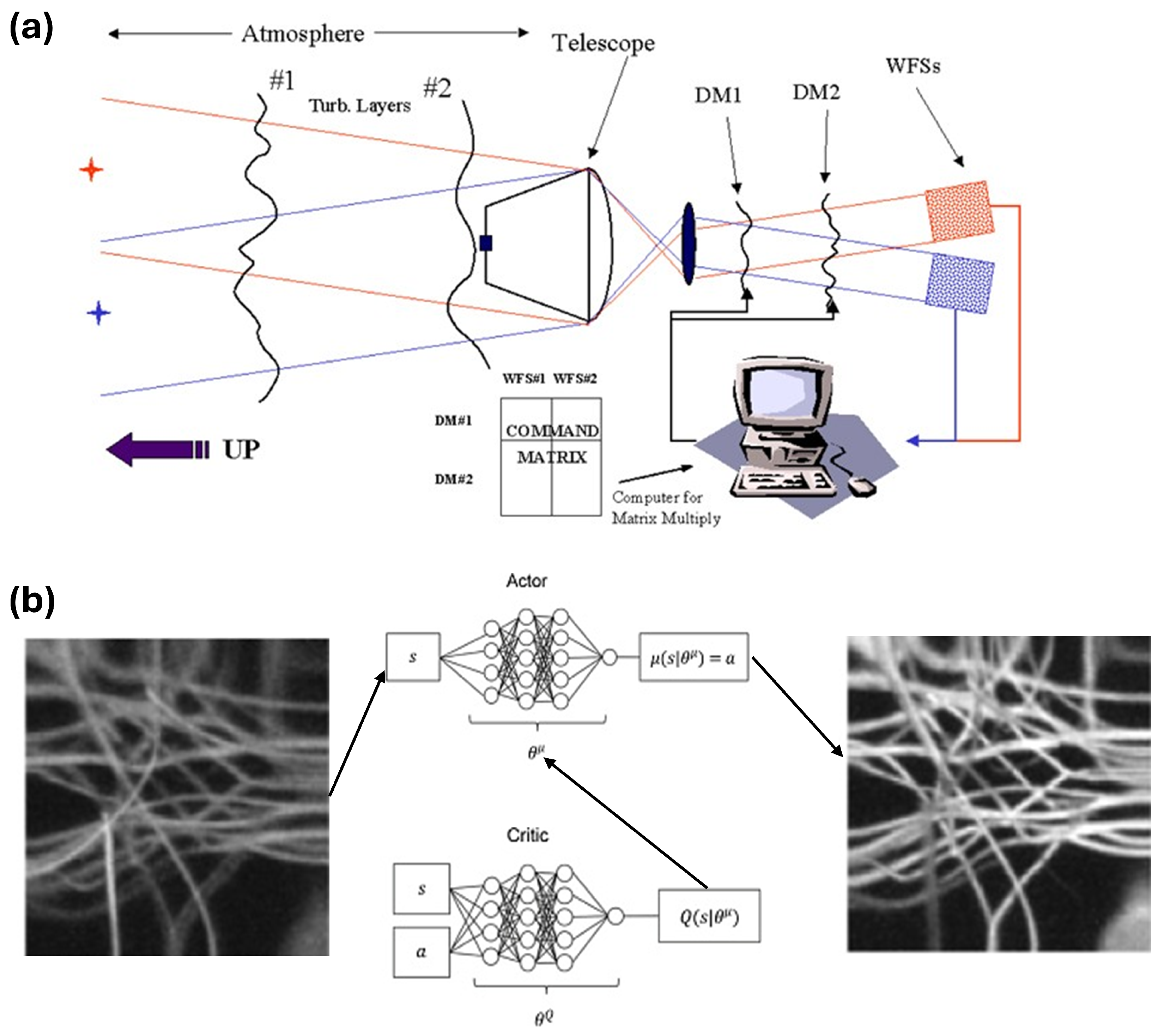
Figure 9. (a) Schematic of MCAO equipped with two DMs and two WFs to perform correction over an extended field of view. Figure reprinted from ref. [40] under the terms of the Creative Commons Attribution-Non-Commercial-NoDerivs 3.0 Germany License. (b) Tissue phantom images from a scanning laser ophthalmoscopes aberrated (left) and corrected (right) [39]. Figure reprinted from ref. [39] under the terms of the OSA Open Access Publishing Agreement.
Jmmp 09 00105 g009

3. Emerging Trends in Laser Material Processing: Opportunities and the Role of PSF and Zernike Polynomials

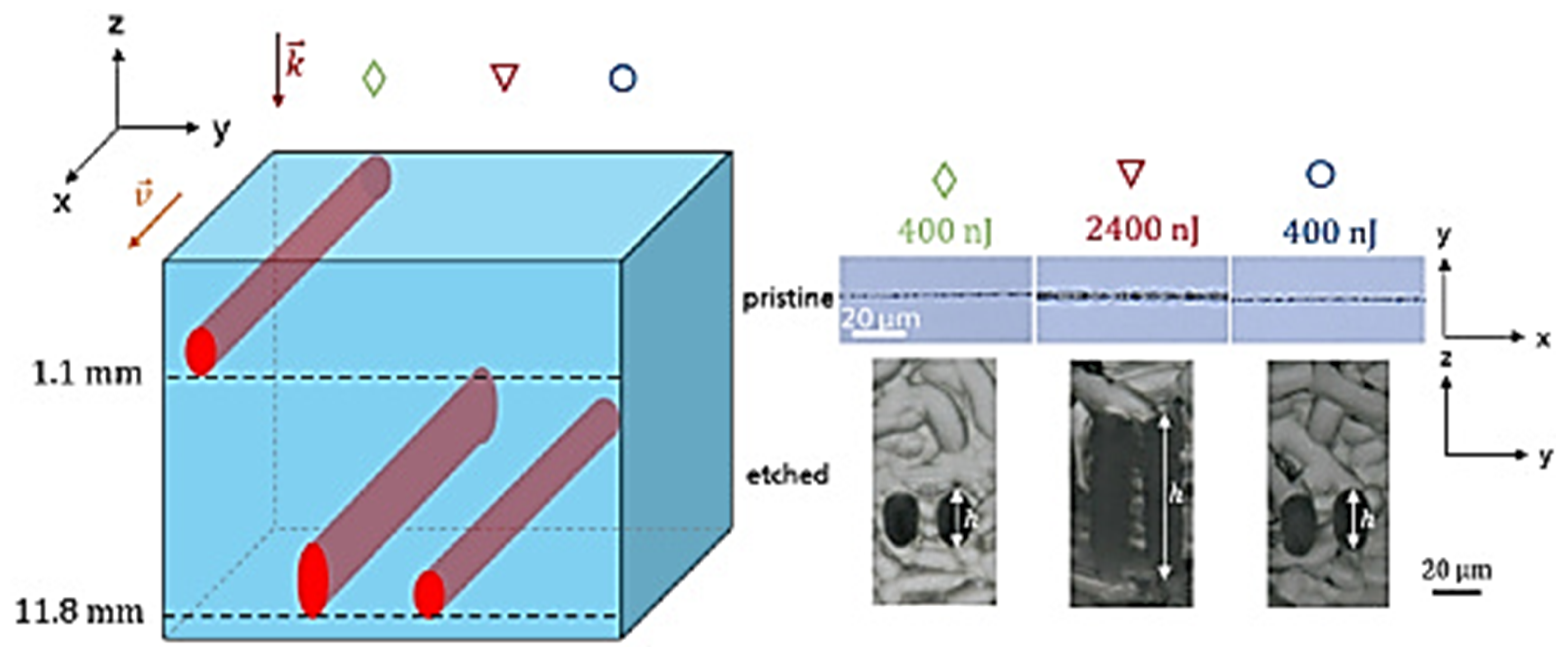
Ultrashort laser pulses and strong focusing conditions generate high peak intensities greater than 1013 W/cm2, which, in turn, lead to ionization due to nonlinear absorption mechanisms in transparent dielectrics like glasses for visible and near-visible wavelengths [41]. The highly localized absorption regions determine volume modifications in transparent dielectrics. The short duration of the pulse offers several further advantages over longer-duration laser pulses such as eliminating plasma creation and, therefore, plasma reflections, thereby reducing collateral damage through the small component of thermal diffusion and other heat transport effects during the much shorter time scale of such laser pulses [42,43]. The generation of aberrative effects limits the laser processing performance. For example, in fused silica, the undesired morphological/structural modifications lead to reduced resistance to etching agents such as aqueous KOH or HF. Thus, etching channels in fused silica with selectivities of more than 1400:1 can be achieved by direct laser writing with a subsequent wet chemical etching process [44]. In these cases, for constant focusing conditions, the intensity profile changes depending on the focusing depth due to spherical aberrations. One way to eliminate this effect is the utilization of spherical aberration-corrected optical systems for a fixed depth. Another way is to adjust the pulse energy as a function of focusing depth. However, the material machining requires higher pulse energies to reach the modification threshold for an extended volume. A performing technical solution for the customized correction of spherical aberrations for ultrashort laser processing is the use of spatial light modulators (SLMs), whose principal mechanism has been described in previous paragraphs. Bisch et al. [45] applied a liquid crystal spatial light modulator (LC-SLM) for aberration correction, enabling the fabrication of low-loss single-mode borosilicate glass-based waveguides over a depth range greater than 1 mm. Kratz et al. [46] reported a depth-independent scanning strategy for generating complex 3D geometries in transparent materials. The authors compared the results of the laser process with the aberration-corrected beam profile using AO elements with those without aberration correction: the main results concern the pulse energy conservation, the uniform etching channel precision in laser propagation direction for all the investigated glass thicknesses, and a depth-independent processing method due to the decoupling of scan strategy from pulse energy (Figure 10).
Recent studies indicate that to reconstruct and simultaneously correct the distorted wavefront, Fourier Transform iterative calculations are necessary. However, some limitations still occur for a real-time analysis. These technical issues are partly resolved by combining the measured wavefront with the “ideal image” reproduced by a machine learning approach that allows for the prediction of the wavefront starting from a distorted point spread function (PSF) image.
In an optical system, the object complex amplitude u 0 is related to the corresponding image u i by the convolution with the PSF of the system [47]:
u i ( x , y ) = P S F ( x , y ) u 0 ( x , y ) .
In turn, the P S F can be written as the square modulus of the Fourier transform ( F T ) of the pupil function (P) of an objective lens described in polar coordinates:
P S F ( x , y ) = | F T { P ( r , θ ) } | 2 .
The analytical expression of the aperture function, describing how light waves are influenced when transmitted through an optical imaging system including the human eye, is given by
P ( r , θ ) = A ( r , θ ) e i { ϕ ( r , θ ) + ω ( r , θ ) } ,
in which A, ϕ and ω , respectively, represent the amplitude, phase and wavefront aberration with respect to the pupil plane. In detail, ω can be written in terms of the Zernike polynomials, as discussed in Appendix A.1:
ω ( r , θ ) = m = 1 a m z m ( r , θ ) ,
where z m is the Zernike polynomials and a m the corresponding Zernike coefficients for the given Zernike mode m.
As detailed in Appendix A.1, the decomposition of these aberrations into a series of modes, specifically Zernike polynomials, allows for effective analysis and correction. Zernike polynomials provide a systematic way to represent wavefront errors. Each polynomial is characterized by two indices nn (radial order) and mm (azimuthal frequency), and they are orthogonal over a unit circle. The coefficients associated with these polynomials, denoted as z(n,m)z(n,m), quantify the contribution of each mode to the overall wavefront error. For example, lower-order aberrations (LOAs) include modes such as defocus and astigmatism, which are critical for basic optical corrections. For instance, the first three rows of the Zernike pyramid (Figure A1) correspond to LOAs, where the highest radial term is 2. Instead, higher-order aberrations (HOAs) are defined by a radial order of 3 or higher and can include more complex distortions, like spherical aberration and coma. Higher-order modes often contain lower-order terms within their expressions, complicating their interpretation [48,49].
The hierarchy of wavefront aberrations, shown in Figure A1, is adopted as a classification reference when considering the effects of the optical aberration in laser processing. In this case, we start to consider that wavefront aberrations can be categorized into lower-order and higher-order aberrations, which significantly influences the performance and accuracy of laser micromachining processes. Lower-order aberrations include spherical aberration, coma and astigmatism. Aberrations primarily affect the overall focus and alignment of the laser beam, leading to a broader focus spot and reduced resolution in micromachining applications. Higher-order aberrations are more complex and include terms like trefoil and quadrafoil. These can lead to significant focal distortions that are detrimental to precision micromachining. For instance, they can result in focal splitting, where different parts of the laser beam focus differently, complicating the machining process.
So, the significance of Zernike coefficients and their associated basis functions in adaptive optics lies in their ability to provide a robust framework for analyzing and correcting optical aberrations. This capability is especially vital in high-precision applications like laser scribing, where even minor deviations can lead to significant errors in material processing outcomes. Specifically, the Zernike coefficients (a set of orthogonal functions defined over a unit circle) quantify the contribution of each Zernike polynomial to the overall wavefront aberration. Each coefficient corresponds to a specific mode of aberration (e.g., tilt, defocus, astigmatism) and is computed from the measured wavefront data. The independence of these coefficients allows for a clear interpretation of how much each mode contributes to the total root-mean-squared (RMS) wavefront error. Higher-magnitude coefficients indicate greater contributions to optical performance degradation, which is critical in applications like laser scribing where precision is paramount. Ultimately, the basis functions z m ( r , θ ) derived from Zernike polynomials serve as mathematical tools for reconstructing wavefronts. In adaptive optics systems, these functions can be employed to model and correct distortions in real-time. The orthogonality of these functions ensures that they can effectively represent complex wavefront shapes without redundancy, allowing for efficient computation and in-time correction strategies during laser processing to obtain products with sub-micron resolutions.

4. AO as a Transformative Technology When Integrated in a Wavefront Shaping System for a High-Power Laser Source

The scaling of the productivity using ultrafast lasers is very demanding and needs simultaneous or sequential process parallelization as well as advanced control over beam shaping, focus correction, and real-time feedback mechanisms [50,51,52,53]. Also, in this case, adaptive optics represent a transformative technology in laser processing, leading to higher precision and efficiency in various manufacturing processes. In detail, the main advantages of integrating AO into micromachining setups are as follows [1,54,55]:
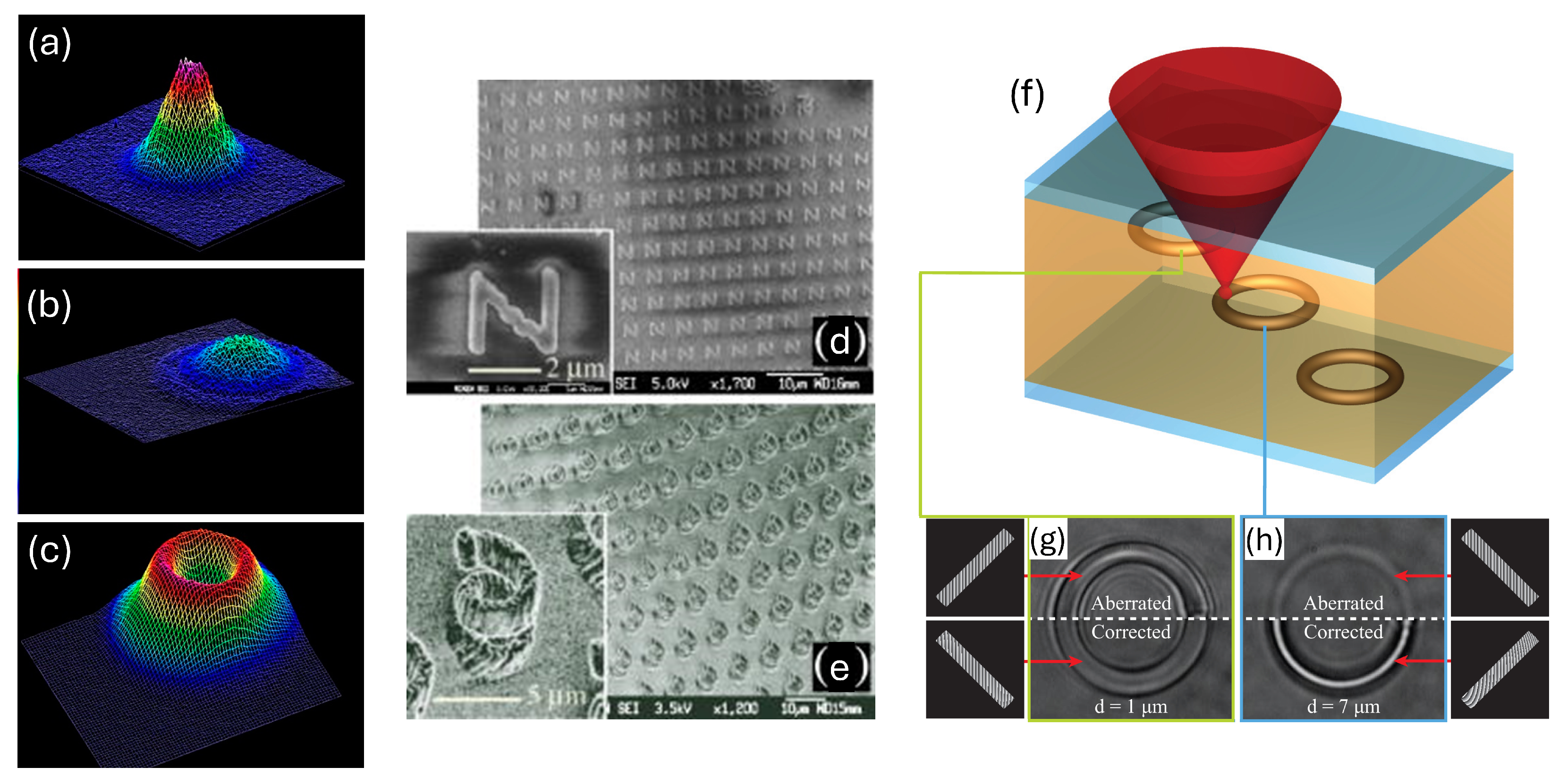
  • Improved Beam Quality: Adaptive optics can modify the Gaussian beam shape typical of lasers into more suitable profiles for specific applications, such as a flat-top or ring-shaped intensity distribution. This modification can enhance the quality of laser marking and drilling processes by providing a more uniform energy distribution at the focus (Figure 11a–c).
  • Aberration Correction: When lasers are focused inside materials, aberrations can distort the beam, leading to inefficiencies in machining. Adaptive optics can correct these aberrations dynamically, ensuring that the laser maintains its diffraction-limited performance throughout the machining process. This is particularly beneficial for ultrafast laser applications where precision is critical.
  • Parallel Processing: Adaptive optics can facilitate parallelization by generating multiple foci from a single laser beam, significantly reducing processing times for high-resolution tasks. This capability is especially advantageous for large-scale or complex three-dimensional fabrications (Figure 11d,e).
  • Dynamic Control: The ability to adjust the beam shape and focus dynamically allows for complex structuring of materials during processing [56]. This flexibility enables manufacturers to tailor the laser’s properties in real-time, accommodating various fabrication tasks without needing to change equipment (Figure 11f–h).
  • Enhanced Material Interaction: By controlling the intensity distribution at the focus, adaptive optics can optimize interactions with different materials, leading to improved outcomes in terms of precision and surface finish.
However, some considerations should be made against using adaptive optics. Implementing adaptive optics adds complexity to the laser micromachining setup, requiring additional components such as wavefront modulators (e.g., deformable mirrors or spatial light modulators) [57]. This complexity can lead to increased costs and maintenance requirements. Moreover, the dynamic nature of adaptive optics systems may introduce stability issues during machining processes, particularly if not properly calibrated or synchronized with the laser operation.
In ultra-short pulsed laser, a master oscillator/power amplifier (MOPA) configuration uses the master oscillator to generate a low-power optical signal that is then amplified by the power amplifier to produce the laser beam. Unfortunately, high-power laser systems with MOPA configurations can face degradation of the overall quality of the output beam due to the deviation of the beam of the master oscillator relative to the power amplifier, as well as for the thermally induced distortion occurring in the gain medium of the power amplifier. These optical aberrations introduce a change in the focal intensity distribution (focal distortion) from its ideal diffraction-limited nature affecting the quality of the textured/scribed materials. Specifically, the focal splitting is related to focusing inside birefringent media, where different polarization modes couple to different refractive indices [1,58,59,60,61]. The challenge is to reach the maximum wavefront compensation in terms of spatial shaping of the laser beam in phase, amplitude and/or polarization. For example, when the laser processing occurs inside a material transverse to the optic axis, an asymmetrical elliptical shape of the diffraction-limited focus is observed. In this case, AO elements, controlling the illumination of the slit placed before the focusing objective lens, generate a circular cross section structure. Thus, the focal intensity will spread in a direction orthogonal to the slit axis, keeping the same axial resolution.
Figure 11. Three-dimensional images of Gaussian (a), flat (b) and inverted-Gaussian (c) laser beam profiles, reprinted from ref. [62] under the terms of the CC BY license. Representative two- and three-dimensional fabrication by parallel processing: (d) the microletter array of ‘N’ fabricated with 28 exposure points in two dimension through the relay lens of a 150 mm focal length; and (e) a three-dimensional microspring array fabricated with the relay lens of an 80 mm focal length (corresponding insets focus on individual structures). Reprinted from Kato et al. [63], with the permission of AIP Publishing. Schematic of dynamic ring fabrication (f) and corresponding images of the same circular trajectories fabricated at depths of 1 μ m (g) and 7 μ m (h) both with and without simultaneous compensation of aberration. Reprinted by ref. [64] under the terms of the OSA Open Access Publishing Agreement.
Jmmp 09 00105 g011
Figure 12 shows the scheme of a wavefront shaping system equipped with a small-aperture DM, a laser source and a Shack–Hartmann sensor.
The input beam, having a wavefront distribution φ i n ( x , y ) , is reflected by the DM and, passing through the laser system, reaches the Shack–Hartmann wavefront sensor. The interaction between the input beam φ i n ( x , y ) and DM is crucial for achieving optimal wavefront shaping before the beam reaches the Shack–Hartmann sensor. To clarify the role played by each element, we describe each step of the wavefront shaping process:
  • Input beam characteristics: The input beam φ i n ( x , y ) typically exhibits some level of distortion or non-uniformity in its wavefront. This could be due to imperfections in the laser source or optical components in the system.
  • Role of DM: DM is strategically placed to manipulate the wavefront of the incoming beam. It consists of an array of actuators (often mechanical pistons) that can adjust the shape of the mirror’s surface. By altering this shape, the DM can compensate for wavefront aberrations present in φ i n ( x , y ) [66].
  • Wavefront correction: As the input beam interacts with the DM, it undergoes a transformation that aims to flatten or optimize its wavefront. The specific adjustments made by the DM are determined based on feedback from the Shack–Hartmann sensor, which measures the wavefront shape and identifies deviations from an ideal planar wavefront [57].
  • Feedback loop: The Shack–Hartmann sensor captures the modified wavefront after it has been shaped by the DM. It analyzes the positions of focal spots created by an array of microlenses, allowing it to calculate parameters such as tip, tilt and curvature of the wavefront [67]. These data are then used to iteratively refine the DM’s adjustments, creating a closed feedback loop that continuously improves wavefront quality.
  • Optimal wavefront shaping: The goal is to achieve a near-perfect wavefront before it reaches any subsequent optical components or processing stages in the laser micromachining setup. This ensures maximum efficiency and precision during laser ablation or machining processes, as a well-shaped beam can more effectively interact with materials [68].
The entire process is mathematically described as follows:
φ i n ( x , y ) + 2 S D M ( x , y ) + F ( x , y ) = φ o u t ( x , y )
where S D M ( x , y ) , F ( x , y ) and φ o u t ( x , y ) are the DM surface distribution, the induced laser wavefront distortion function and the output wavefront distribution, respectively [69]. The relationship between the input and the output wavefront through the laser system is linear and can be described in terms of the transmission function H ( x , y ) :
H ( x , y ) = φ i n ( x , y ) + F ( x , y )
If the initial conditions were expressed by the output wavefront φ o u t ( x , y ) and the DM surface S D M ( 0 ) ( x , y ) , the first compensation DM surface distribution S D M ( 1 ) ( x , y ) , representing the wavefront shaping in the laser system, can be calculated as follows:
H ( x , y ) = φ o u t ( x , y ) 2 S D M ( 0 ) ( x , y ) S D M ( 1 ) ( x , y ) = 1 2 φ a i m ( x , y ) H ( x , y )
by considering the wavefront distribution φ a i m ( x , y ) and the transmission function H ( x , y ) . When the laser system itself (i.e., the aberrations) is linear, the output flattening wavefront distribution cannot be obtained after the first wavefront correction. So, the iterative method should be applied:
S D M ( n + 1 ) ( x , y ) = 1 2 φ a i m ( x , y ) φ o u t ( n ) ( x , y ) + S D M ( n ) ( x , y )
where S D M ( n ) ( x , y ) represents the DM surface distribution at the n t h iteration, and for n = 0 , it represents the initial DM surface; φ o u t ( n ) ( x , y ) represents the n t h output wavefront distribution, and for n = 0 , it represents the initial wavefront [70].
Hence, the dynamical adjustment of the laser beam profile by the simultaneous AO correction of aberration effects is essential to induce material removal and surface modification with sub-micron accuracy. This enables adaptive welding strategies, such as seam tracking and gap bridging. In fact, ultrafast lasers combined with AO can track seams with high precision due to their ability to rapidly adjust focus and intensity. This is particularly useful for materials with intricate geometries or uneven surfaces [1]. AO excels in handling complex weld geometries (e.g., curved seams) due to its ability to dynamically adjust beam parameters. Moreover, AO allows ultrafast lasers to adaptively bridge gaps by modifying the beam profile or oscillating the focal point. This ensures consistent energy delivery across varying material separations. With increased tolerance to joint gaps, AO reduces the need for precise machining or clamping during part preparation. This lowers manufacturing costs and shortens production times. In particular, ultrafast lasers excel in processing transparent materials (e.g., glass) through nonlinear absorption mechanisms. AO enhances this capability by enabling precise 3D structuring and deep penetration welding, such as forming molten structures up to 5 mm deep in quartz glass [71]. Furthermore, parallelization enabled by AO reduces processing times by allowing for the simultaneous processing of multiple areas or rapid switching between focal positions [1]. All these advancements make adaptive optics a transformative technology in laser welding, offering unparalleled precision, efficiency, and adaptability for industrial applications.
In laser scribing, AO systems that implement piston, tip, and tilt corrections allow for the following: (1) the stabilization of the beam position and focus; (2) compensation for disturbances such as jitter or mechanical vibrations; and (3) enhanced dynamic response performance through advanced control methods [33]. Below are further details on piston, tip, and tilt parameters as critical components in adaptive optics (AO) systems. Piston, tip, and tilt parameters are crucial in adaptive optics (AO) for defining the reference surface and correcting wavefront aberrations. The piston parameter in AO significantly impacts wavefront correction by addressing the average optical path length discrepancies across the wavefront. It effectively shifts the entire wavefront up or down, ensuring that all parts of the wavefront are aligned to a common reference plane. This adjustment is crucial for achieving coherent light propagation and minimizing overall wavefront error, particularly in systems with segmented mirrors. Proper piston correction enhances image quality by reducing residual aberrations, thereby improving the system’s ability to deliver diffraction-limited imaging. Tip and tilt adjust the wavefront’s angle, addressing misalignments that affect image quality. By accurately aligning the wavefront, tip correction enhances the point spread function (PSF), leading to increased resolution and contrast in the final image. This correction is particularly important in dynamic environments, such as astronomy and vision science, where even minor shifts can significantly impact image clarity and details. Moreover, by adjusting the tilt of the wavefront, tip–tilt mirrors align the incoming light beams to a common focal point in view of various processing applications. Tip–tilt stages allow for precise control over the angular position of laser beams. By adjusting the tilt and tip angles, these systems can compensate for variations in alignment and surface flatness, ensuring that the laser remains focused on the desired target area [33].
A further optimization of these processes is now achieved by the integration of machine learning with Shack–Hartmann and pyramidal sensors. For instance, using reinforcement learning with pyramidal sensors has shown superior performance in challenging conditions, outperforming traditional methods. The use of Bessel beams and acousto-optic deflectors (AODs) in laser processing has advanced significantly, enabling faster, more efficient, and precise fabrication techniques. Bessel beams are non-diffractive optical beams with self-healing properties, making them ideal for high-precision laser processing tasks such as to fabricate high-aspect-ratio structures in two-photon polymerization (TPP). This approach enables volumetric printing without the need for point-by-point scanning, thereby overcoming traditional limitations in serial processing [72]. On the other hand, Acousto-optic deflectors (AODs) are critical for achieving extremely fast beam deflection in laser systems. AODs use sound waves to dynamically modulate the refractive index of a medium, enabling rapid beam steering with microsecond response times. This capability is essential for applications requiring precise and fast beam positioning, such as 3D printing. Then, the combination of AODs with Bessel beams allows for ultrafast scanning over large areas while maintaining the unique properties of the Bessel beam. This integration is particularly useful in GHz burst-mode femtosecond lasers for cutting dielectrics or other challenging materials [73,74]. Additionally, machine learning aids in mitigating nonlinearities in wavefront sensing, further enhancing image quality and system robustness. This synergy enables AO systems to achieve higher fidelity in real-time corrections. Recently, advances in machine learning, particularly deep learning, have led to innovative solutions for depth estimation and image restoration from defocused images captured across different axial planes. For example, defocus segmentation techniques aim to distinguish between sharp and blurred regions within an image. Using algorithms like Pulse Coupled Neural Networks (PCNNs) combined with Local Binary Patterns (LBPs) can effectively segment focused areas from defocused ones, facilitating further processing or analysis of specific regions within an image [75,76,77]. A recent study introduces the Two-headed Depth Estimation and Deblurring Network (2HDED:NET), which simultaneously addresses depth estimation and image deblurring. This model utilizes a shared encoder for both tasks, allowing it to leverage the relationship between depth information and defocus characteristics. It has shown superior performance on benchmark datasets such as NYU-v2 and Make3D, outperforming traditional models that treat these tasks separately [78].
Nevertheless, some efforts are still necessary to (i) accurately predict the low-order aberrations (mainly astigmatism and spherical aberration) versus the Zernike-mode coefficients and the number of datasets; (ii) reduce the data transfer speed of the image sensor [47]; and (iii) avoid long processing times for high-resolution tasks, which is still an issue due to the point-based nature of laser processing when creating multiple foci simultaneously, even though adaptive optics is able to enhance processing speed through parallelization. The need for continuous adjustments to maintain focus across three-dimensional structures adds to this challenge [1].

5. Metasurfaces for Aberration Correction in Laser Scribing Processes

Recent advancements in metasurfaces have significantly improved wavefront aberration correction. These two-dimensional optical materials manipulate light through subwavelength structures, allowing for efficient phase control and reduced chromatic aberration compared to conventional optics [79]. Dielectric metasurfaces, in particular, have shown enhanced performance by achieving steep phase gradients and enabling functionalities that combine multiple optical components into a single device. Recent developments have integrated metasurfaces with conventional optical components, enhancing imaging systems and enabling functionalities like beam steering and polarization control. These advancements facilitate applications in high-end imaging and computer vision, demonstrating the potential for real-time wavefront correction in various optical devices.
Furthermore, metasurfaces have shown great promise in correcting optical aberrations by providing precise control over the phase of transmitted or reflected light [80]. Specifically, by customizing the geometry of the meta-atoms, metasurfaces can introduce tailored phase shifts that counteract aberrations [81]. A specific application of metasurfaces is in metalenses, which utilize arrays of nanoscale structures to focus light. These lenses can be engineered to compensate aberrations by adjusting the phase distribution across the lens surface (Figure 13). In addition, metasurfaces can achieve diffraction-limited focusing across a broad wavelength range, maintaining high efficiency. This is particularly important in laser scribing, where precise energy delivery is essential for effective material processing. For instance, certain metasurfaces have demonstrated focusing efficiencies of up to 90% at specific wavelengths [82]. Recent developments have introduced active metalenses with reconfigurable focusing capabilities. These systems can adjust the focal spot’s position in three-dimensional space, allowing for greater flexibility during laser scribing operations. By mechanically tuning the arrangement of multiple metalenses, users can achieve precise control over the focal point [83]. The capability of metalenses to focus laser beams with exceptional precision (no aberration effects) allows for accurate scribing of transparent materials like glass and polymers without leading to micro-cracks around the scribed area.
Metasurfaces used for aberration correction can be either passive, with fixed functionalities, or active, allowing for tunable and reconfigurable functions. Using metasurfaces can lead to more compact optical systems and enable novel properties and applications [80]. One approach involves using cascaded metasurfaces to achieve adaptive aberration corrections coordinated with focus scanning. This method allows for precise dynamic control of electromagnetic waves. In detail, by rotating two cascaded transmissive metasurfaces, adaptive aberration corrections can be achieved in tandem with focus scanning [85]. The rotation of the metasurfaces globally changes their phase profiles (Figure 14). By adjusting the mutual rotation angle between two layers in twisted metasurfaces, the reflected EM wave can be focused on a specific location. This allows for dynamic control of the focal spot in both two-dimensional and three-dimensional spaces.
In laser texturing setups, metasurfaces can be mounted on spherical surfaces to correct coma aberrations. Attaching metasurfaces to the surfaces of refractive optical elements allows for the analytical derivation of the desired phase profile; this setup can compensate for 80% of chromatic and 70% of spherical aberration. In these cases, the metasurface layer consists of an array of dissimilar cylindrical amorphous silicon nanoposts with different diameters placed on a subwavelength periodic hexagonal lattice and embedded in a flexible polydimethylsiloxane substrate. An aluminium oxide layer is located between the polydimethylsiloxane and the amorphous silicon post. The arbitrary shape of the object surface distorts the wavefront of transmitted light, but the metasurface corrects this [86].
Metasurfaces, which are engineered surfaces with subwavelength features, can manipulate light at unprecedented levels. Their integration with Vertical-Cavity Surface-Emitting Lasers (VCSELs) allows for custom-tailored optical wavefront shaping, enabling functionalities such as beam collimation, steering, and the generation of complex beam profiles (e.g., Bessel and vortex beams) directly from the laser output. By shaping the emitted laser beam more effectively, they ensure that the light interacts with the material in a more controlled manner, leading to improved scribing quality [87,88].
In summary, the integration of metasurfaces into laser scribing processes presents a cutting-edge solution for overcoming optical aberrations, enhancing precision and efficiency in various applications.

6. Conclusions

Adaptive optics integration leads to substantial progress in high-power laser applications, providing enhanced precision, efficiency and versatility that are crucial for contemporary technological requirements. By dynamically adjusting the laser beam’s wavefront, AO systems allow the identification and correction of the various optical aberrations, particularly depth-dependent spherical aberrations, that can be complicated due to the non-uniform refractive index of materials. However, the integration of AO systems with an existing laser processing setup is still a primary challenge because it requires precise alignment and calibration, which can be technically demanding. Moreover, the cost of adaptive optical elements and their complexity may hinder widespread adoption, especially in smaller manufacturing environments.

Author Contributions

Conceptualization, F.N. and E.F.; methodology, C.C. and V.C.; investigation, P.P. and E.F.; resources, V.C., D.C. and F.N.; data curation, C.C. and P.P.; writing—review and editing, C.C, P.P., V.C., D.C., F.N. and E.F.; supervision, E.F. All authors have read and agreed to the published version of the manuscript.

Funding

This research received no external funding.

Institutional Review Board Statement

Not applicable.

Informed Consent Statement

Not applicable.

Data Availability Statement

No new data were created or analyzed in this study. Data sharing is not applicable to this article.

Conflicts of Interest

The authors declare no conflicts of interest.

Abbreviations

The following abbreviations are used in this manuscript:
AOAdaptive Optics
MTFModulation Transfer Function
OTFOptical Transfer Function
PSDPoint Spread Function
LSALongitudinal Spherical Aberration
TSATransverse Spherical Aberration
DMDeformable Mirror
SLMSpatial Light Modulator

Appendix A. Optical Imaging Processes and Aberration

The physical process of image formation is a widely covered yet consistently fascinating topic since it is the basis of our ability to see. Light is made up of electromagnetic waves with a wavelength of a few tenths of a micrometre, much smaller than the dimensions of everyday objects. In these conditions, many of the light propagation phenomena can be described with good approximation using geometric optics. Let us consider a small segment of a wave surface: when the wave propagates through a medium, refracts or reflects at the separation surface of the two different media, the segment considered follows a straight path if the medium is homogeneous, but changes direction according to Snell’s law at the separation surface. The trajectory of light energy that coincides in isotropic media with that of the wave surface segment is a light ray. Ray optics or geometric optics, which is a good approximation whenever the dimensions of the surface encountered by the ray are large compared to the wavelength, allows for the design of lenses, mirrors and optical instruments.
However, geometric optics is often insufficient to understand the physical processes that underlie the formation of optical images, the structure of which is always affected by diffraction phenomena. Therefore, the optical imaging process must constantly take into account the wave nature of light. The study of image formation was initially approached by considering perfectly spherical, flat or monochromatic light waves. Taking into account that the wavelength of visible light is about half a thousandth of a millimeter, it can be easily understood that small imperfections in optical instruments, known as aberrations, can cause appreciable differences compared to the ideal case. Thus, the study of aberrations is fundamental in the design and construction of optical systems and instruments [89,90].
An optical system can be effectively characterized using the Modulation Transfer Function (MTF) and the Optical Transfer Function (OTF). Moreover, the correlation between wavefront, MFT and OTF is critical for assessing and improving optical performance. In fact, both MTF and OTF provide essential metrics for understanding how well these systems can reproduce detail and contrast from objects to images, thereby guiding design improvements and quality assessments in optical engineering. Specifically, OTF describes how well an optical system can transfer contrast from an object to an image. OTF is given by the ratio of image contrast to object contrast plotted as a function of spatial frequency, and takes into account the phase shift between the position of the actual image and the position of the ideal one. Instead, MFT measures the ability of the optical system to transfer contrast from the object under study to the intermediate image plane at a specific resolution. MFT is also related to the point spread function (PSD), which is the image of a point source of light (commonly referred as the Airy disk) from the object projected by the objective of the optical system onto the intermediate image plane. The distribution of light intensity observed at the image plane is affected both by optical aberrations and numerical aperture variations, influencing the PSD shape. Finally, the sum of the PSDs produced by an object (specimen) in a diffraction-limited microscope includes the diffraction pattern produced at the image plane [13]. Employing the Modulation Transfer Function (MTF) in conjunction with wavefront measurements provides a comprehensive approach to optical system analysis, particularly for reducing aberrations.
Optical aberrations are due to the fact that the outgoing wave is not actually spherical, even though the wave surface differs more or less from a spherical surface. It is clear that the smaller this difference, the less important the aberration. There is a threshold value of the difference below which the wave is practically indistinguishable from a spherical wave, where the aberration is unobservable and therefore irrelevant [91]. We focus our attention on the definition of wave surface which is considered as a locus of points where the vibration of the wave takes on the same phase, known as a geometric surface. For it to make physical sense, however, it is necessary to specify the operations that must be performed to locate it. To do this, interference phenomena are used, i.e., the wave under examination is made to interfere with a wave whose phase is known and the interference fringes are observed. In the highs, the two waves have the same phase (unless multiples of 2 π ), in the lows, they have the opposite phase. Let us now suppose that we change the phase of the wave under examination by the same quantity Δ ϕ at all points in space, keeping fixed that of the reference wave. The whole set of fringes will move rigidly: if, for example Δ ϕ = π , the dark fringes take the place of the light fringes and vice versa. However, if Δ ϕ is sufficiently small, the transverse displacement of the fringes is so small as to not be observable. The limit value depends on the sensitivity of the measurement methods; in practice, a displacement of the fringes equal to a quarter of the distance between two adjacent light fringes is at the limit of observability. We will therefore assume for Δ ϕ the limiting value of 2 π /4 = π /2. Ultimately, at every point of the wave, the phase can only be determined with a precision equal to π /2; vice versa, if we want to locate a point where the phase has a certain value, we can only do so with an uncertainty equal to λ /4 in a direction perpendicular to the wave surface [92]. This means that, physically, the wave surface is not a geometric surface, but is defined within a thickness equal to λ /4. A surface that differs from a spherical surface by protuberances or depressions of height less than λ /4 is indistinguishable from an ideal spherical surface. Thus, the aberrations of waves less than λ /4 are negligible. This is the Rayleigh’s quarter-wave criterion for aberrations, usable only with monochromatic light [93].

Appendix A.1. Classification of Aberrations

An aberration is a property of an optical system which causes light to be scattered in a region rather than focusing on a single point. In other words, there is an aberration when, after transmission through the optical system, light coming from a point object does not converge to (or diverge from) a single point on the corresponding image. The nature and characteristics of deformity depend on the types of aberrations that can be classified into two large families:
  • Lower-order aberrations (0, 1st and 2nd order);
  • Higher-order aberrations (3rd, 4th, …order).
Lower-order aberrations (LOAs) is a term used in wavefront technology to describe second-order Zernike polynomials representing conventional focusing aberrations in ophthalmology (myopia, hypermetropia and astigmatism). LOAs include common refractive errors like myopia, hyperopia and astigmatism, which can be corrected with lenses.
Instead, higher-order aberrations (HOAs) are optical imperfections that cannot be corrected by using standard lenses. HOAs are typical of the eyes and are today more widely recognized than in the past thanks to significant developments in technology that allowed us to diagnose them correctly. Indeed, the description of the effect of an optical system (such as the properties of the eye on image quality) can be performed by approaches involving image plane metrics [94].
While LOAs account for the majority of visual distortion, addressing HOAs can enhance visual quality, particularly in cases with significant irregularities like keratoconus. The relationship between LOAs and HOAs is significant as changes in pupil size and lens curvature during accommodation can influence both types of aberrations.
Figure A1 shows a scheme of the most common forms of aberrations created when a wavefront passes through optical systems, such as eyes, with “imperfect vision”. A theoretically perfect eye (top) is represented by an aberration-free flat plane, known by reference as a piston.
Aberrations whose order n is between 0 and 2 are named the following:
  • Piston ( Z 0 0 ), tip ( Z 1 1 ) and tilt ( Z 1 1 ) representing the reference surface;
  • Defocus ( Z 2 0 );
  • Astigmatism ( Z 2 ± 2 ).
Higher-order aberrations are as follows:
  • Spherical aberration, SA, (Primary SA Z 4 0 , Secondary SA Z 6 0 , …);
  • Coma ( Z 3 ± 1 );
  • Distortion.
Optical aberrations are also classified into the following:
  • Monochromatic aberrations: These depend on the geometry of the optical system and are therefore observed with both refracted and reflected light. Their name depends on the fact that they are present even when monochromatic light is used. These are divided into the following:
    • Axial-type aberrations
      They occur when certain light rays incident on the optical system are too far from the optical axis and are affected by the spherical shape of lenses and mirrors (a condition in which the paraxial approximation is not valid). Spherical (or sphericity) aberration falls into this category.
    • Extra-axial aberrations
      They occur with light from extended objects (i.e., all non-point objects) and from objects not arranged on the optical axis. The following aberrations fall into this category:
      -
      Coma;
      -
      Astigmatism;
      -
      Distortion;
      -
      Field curvature.
    In high-power laser applications, the presence of axial- and extra-axial-type aberrations can alter the ideal diffraction-limited nature of a laser’s focal intensity distribution. This distortion can result in less-effective material modification during processes like cutting or engraving, where precise control over the laser focus is essential. Recently, by addressing both lower-order and higher-order aberrations through adaptive optics and precision optical design, manufacturers can enhance machining quality and efficiency, leading to better final product performance.
  • Chromatic aberrations: These depend on the dispersion of the optical system, i.e., changes in the refractive index of the lens materials as the wavelength changes. Due to dispersion, focusing will not occur at a single point. Chromatic aberration does not affect mirrors and does not occur in lenses when monochromatic light is used. Figure 2 shows examples of axial chromatic aberration (a) and lateral chromatic aberration (b), respectively.
Figure A1. Schematization of the most common forms of aberrations created when a light wavefront passes through eyes with imperfect vision. Image courtesy of Alcon Inc., Fort Worth, TX, USA.
Jmmp 09 00105 g0a1
Figure A2. Scheme of axial chromatic (a) and lateral chromatic (b) aberration.
Jmmp 09 00105 g0a2
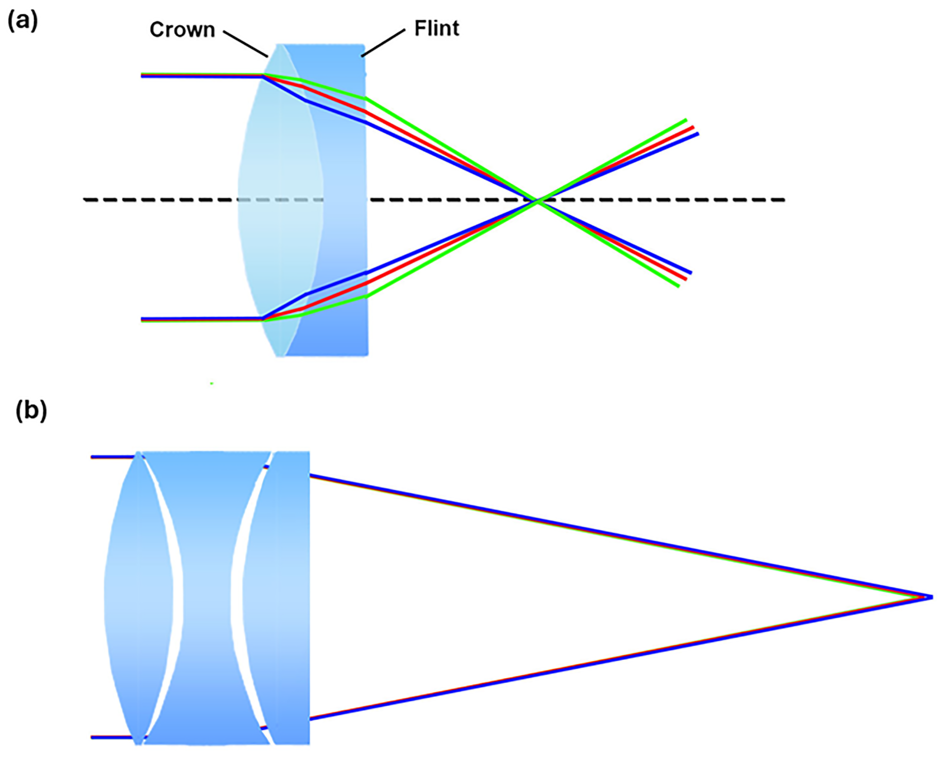
A decisive step in correcting chromatic aberrations was the use of the achromatic doublet (Figure A3a), a converging lens coupled with a diverging lens of a different material (crown–flint). The refractive index of flint glass is not linear at all wavelengths; therefore, chromaticism is reduced but not eliminated. The problem is overcome by adding a glass characterized by low dispersion such as fluorite, thus the so-called apochromatic (or Cooke’s) triplet is realized. In this way, the three fundamental colors, red, blue and green, converge on the same focus (Figure A3b).
Figure A3. Schematic for the correction of chromatic aberration with achromatic doublet (a) and achromatic triplet (b).
Jmmp 09 00105 g0a3

Appendix A.1.1. Tilting and Defocus

Tilting is an optical phenomenon that occurs when a system is not properly aligned with respect to its axis, leading to the creation of a prismatic effect. This aberration is often overlooked as it is much less significant than defocus and astigmatism. In the case of defocus, the optical system being examined is aberration-free, but the power with which the rays reach the detector is incorrect. This results in the rays converging at a point of focus that is on the optical axis but does not coincide with the screen, i.e., the detector. In essence, the light rays converge or diverge inaccurately, causing an image that will be out of focus. Defocus is thus an aberration related to the dioptric power of an optical system; if light rays are concentrated before or after the target, the image will be blurred. Classic examples are refractive errors in the human eye (Figure A4): when light rays focus before the retina, the eye is myopic (negative defocus); conversely, when light rays focus after the retina, the eye is hypermetropic (positive defocus). It is possible to correct these defects by using converging lenses in the case of hypermetropia and diverging lenses in the case of myopia.
Figure A4. Defocus resulting in myopia (a) and hyperopia (b).
Jmmp 09 00105 g0a4

Appendix A.1.2. Astigmatism

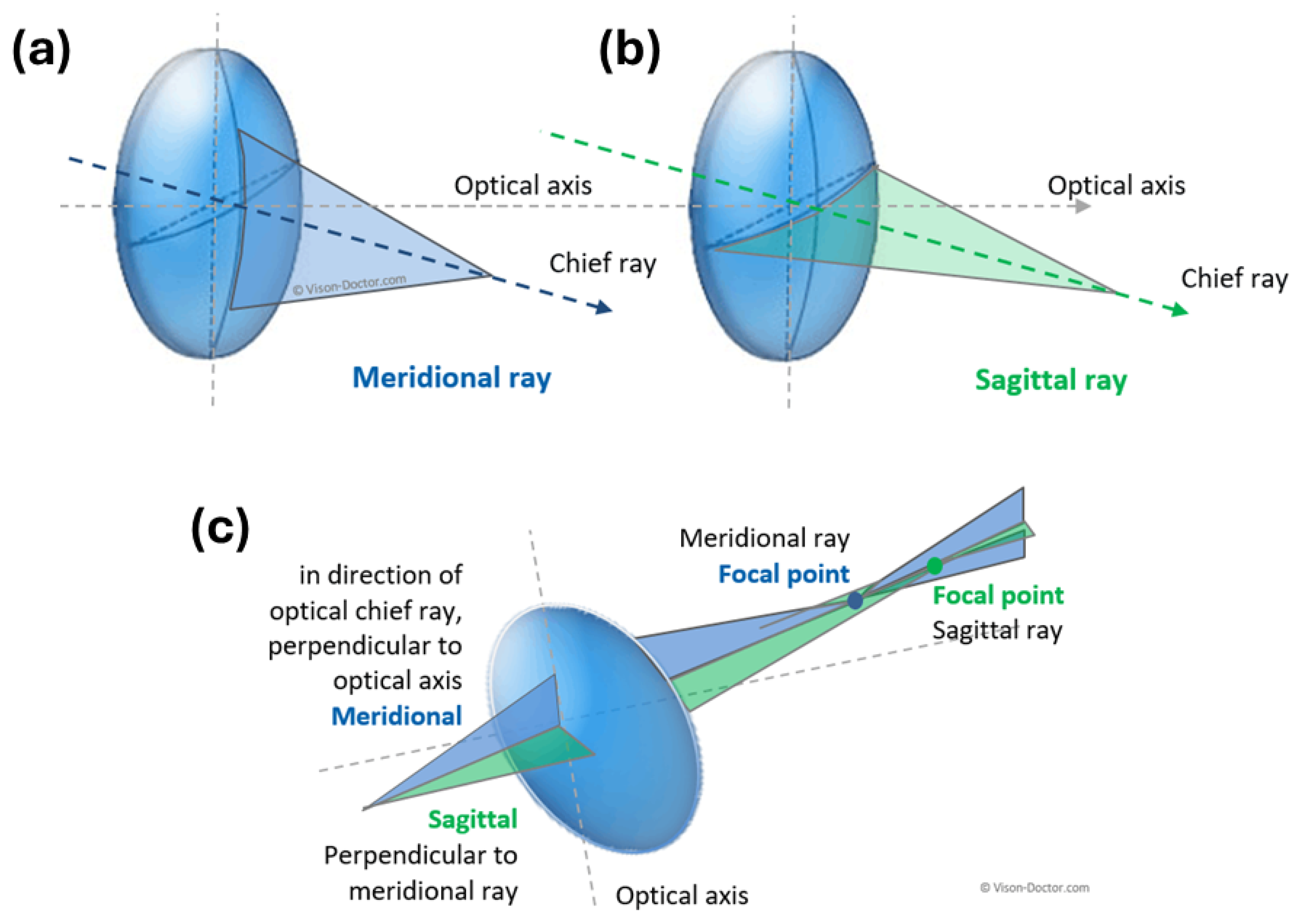
In the presence of aberration from astigmatism, the optical system has a specificity: different focuses for rays propagating in two orthogonal planes. If an astigmatic optical system is used to form the image of a cross, the horizontal and vertical lines will be in focus at different distances. The term comes from Greek, where the prefix “a” stands for a negation and the word σ τ ι ´ γ μ α (stigma) means “sign, point, hole”. Considering a point source, an astigmatic optical system provides an elliptical image. Astigmatism occurs when the principal meridians (tangential and sagittal) of an optical system focus light rays at different positions, as illustrated in Figure A5 [95].
Figure A5. Schematic of the different focus of meridional ray (a) and sagittal ray (b) and the corresponding formation of astigmatism (c). Image adapted with permissions from www.vision-doctor.com.
Jmmp 09 00105 g0a5
Oblique astigmatism occurs when light rays passing obliquely through an optical system are refracted through the diaphragm differently along two mutually perpendicular planes, leading to a difference in focus between the oblique rays and making the image blurred and distorted [96]. In fact, astigmatism of the oblique beams affects both sharpness and position of the image. Even when the oblique astigmatism is corrected, the field curvature, as we will discuss shortly, is still present [97]. Oblique-beam astigmatism occurs with objects (or parts of objects) not placed on the optical axis, but can also be observed in optical systems that are symmetrical with respect to a rotation about the optical axis. In the analysis of the astigmatism of oblique beams, rays are considered starting from a given point P of the object (Figure A6) and propagating in the tangent plane (represented in violet) comprising the point P and the lens axis Q Q 1 , and in the sagittal plane (in grey) orthogonal to the tangent plane, passing through P and the lens). If there is this type of astigmatism, the rays propagating in the tangent plane (transverse rays) and in the sagittal plane (sagittal rays) are concentrated at different points T 1 and S 1 . T 1 and S 1 indeed refer to the tangential and sagittal focal lengths, respectively. Specifically, tangential focal length ( T 1 ) is the distance from the lens to the point where rays in the tangential plane converge. Instead, sagittal focal length ( S 1 ) is the distance from the lens to the point where rays in the sagittal plane converge. The difference between T 1 and S 1 provides a measure of astigmatism. When T 1 and S 1 coincide, there is no astigmatism; when they differ, it indicates the presence of astigmatism. The magnitude of oblique astigmatism can be then expressed as | T 1 - S 1 |. This relationship highlights how variations in lens shape and light incidence angles can lead to different focusing characteristics in optical systems. So, understanding this relationship is vital for designing corrective lenses and optical systems that minimize aberrations and enhance image quality [98,99].
Figure A6. Schematic of oblique astigmatism. Image adapted from https://it.wikipedia.org/wiki/File:Stigmatism.svg (accessed on 21 February 2025) and reused under the terms of the CC BY-SA 3.0 license.
Jmmp 09 00105 g0a6
In more detail, oblique-beam astigmatism is a specific type of optical aberration that occurs when light rays strike a lens at an angle, rather than perpendicularly. This results in different focal points for rays in the tangential (meridional) plane compared to those in the sagittal plane. The rays create a geometric shape known as Sturm’s conoid, which has two line foci—one horizontal and one vertical. This phenomenon is particularly relevant in the context of spherical lenses and can significantly affect image quality. The cause of oblique astigmatism is rooted in the lens’s curvature and the angle at which light enters. When light enters a lens obliquely, it is refracted differently depending on whether it passes through the tangential or sagittal meridians. This leads to variations in focal lengths across different planes, resulting in blurred or distorted images [100]. As schematized in Figure A6 and occurring in specific conditions in the optical systems, the relationship between a point (often referred to as point P) and the axis of the lens (denoted as QQ1) is crucial for understanding how oblique astigmatism manifests. When point P is displaced from the optical axis QQ1, rays emitted from P will strike the lens at an angle, leading to oblique astigmatism. The chief ray from point P will pass through the center of the lens entrance pupil but will not coincide with the optical axis, resulting in different foci for tangential and sagittal planes. As a consequence, optical systems exhibit varying degrees of astigmatism depending on how far point P is from QQ1. The further away point P is from this axis, the greater the oblique astigmatism observed due to increasing angular incidence of light rays.
We define the optical system as rotationally asymmetrical when it is not symmetrical around the optical axis. This may occur by design (as in the case of cylindrical lenses) or possibly be due to surface processing errors of the components or their possible misalignment. This type of astigmatism is typical of the human eye and is due to imperfections in the shape of the cornea or lens. Instead, the marginal astigmatism is a condition in which light rays passing through the edge or periphery of an optical system are deflected differently than the central rays. This causes a discrepancy in focus between the peripheral and central rays, leading to the formation of two different focus points. The distance between the two focus points corresponds to the degree of created astigmatism. In other words, marginal astigmatism primarily affects the image quality at the edges of the visible area, making objects located in these areas less sharp than those in the center.

Appendix A.1.3. Spherical Aberration

Spherical aberration occurs when an optical system differently focuses paraxial rays, i.e., the light rays close to the optical axis, and marginal rays, i.e., the more peripheral light rays. Spherical aberration depends on the optical aperture and is greater as the distance between the paraxial and marginal rays increases. As in the case of a spherical concave mirror on which the reflection phenomenon occurs, the rays incident near its center (Figure A7a) and parallel to the optical axis are reflected in the direction of the first point of focus (F), while the rays hitting the most marginal part of the mirror (Figure A7b) tend to focus into a new focus ( F ). The distance separating the two focus points is called spherical aberration (Figure A7c) and includes both axial and monochromatic aberrations.
Figure A7. Formation of two different focus points on a spherical concave mirror (a,b), leading to the creation of spherical aberration (c). Image adapted from www.andreaminini.org (accessed on 21 February 2025), under the terms of the CC BY 4.0 license.
Jmmp 09 00105 g0a7
A distinction is made between positive and negative spherical aberration (Figure A8) depending on where the rays focus. Positive or negative spherical aberration occurs when the peripheral rays focus before or after the focal plane, respectively.
Figure A8. Difference between positive (a) and negative (b) spherical aberration.
Jmmp 09 00105 g0a8
In the case of positive spherical aberrations, the marginal rays focus before the paraxial rays; conversely, in the case of negative spherical aberrations, the marginal rays focus after the paraxial rays. The distance between the paraxial and marginal foci is known as longitudinal spherical aberration (LSA). The spherical aberration measured in the vertical axis is known as transverse spherical aberration (TSA).

Appendix A.1.4. Spherical Aberration of a Diopter and of a Thin Lens
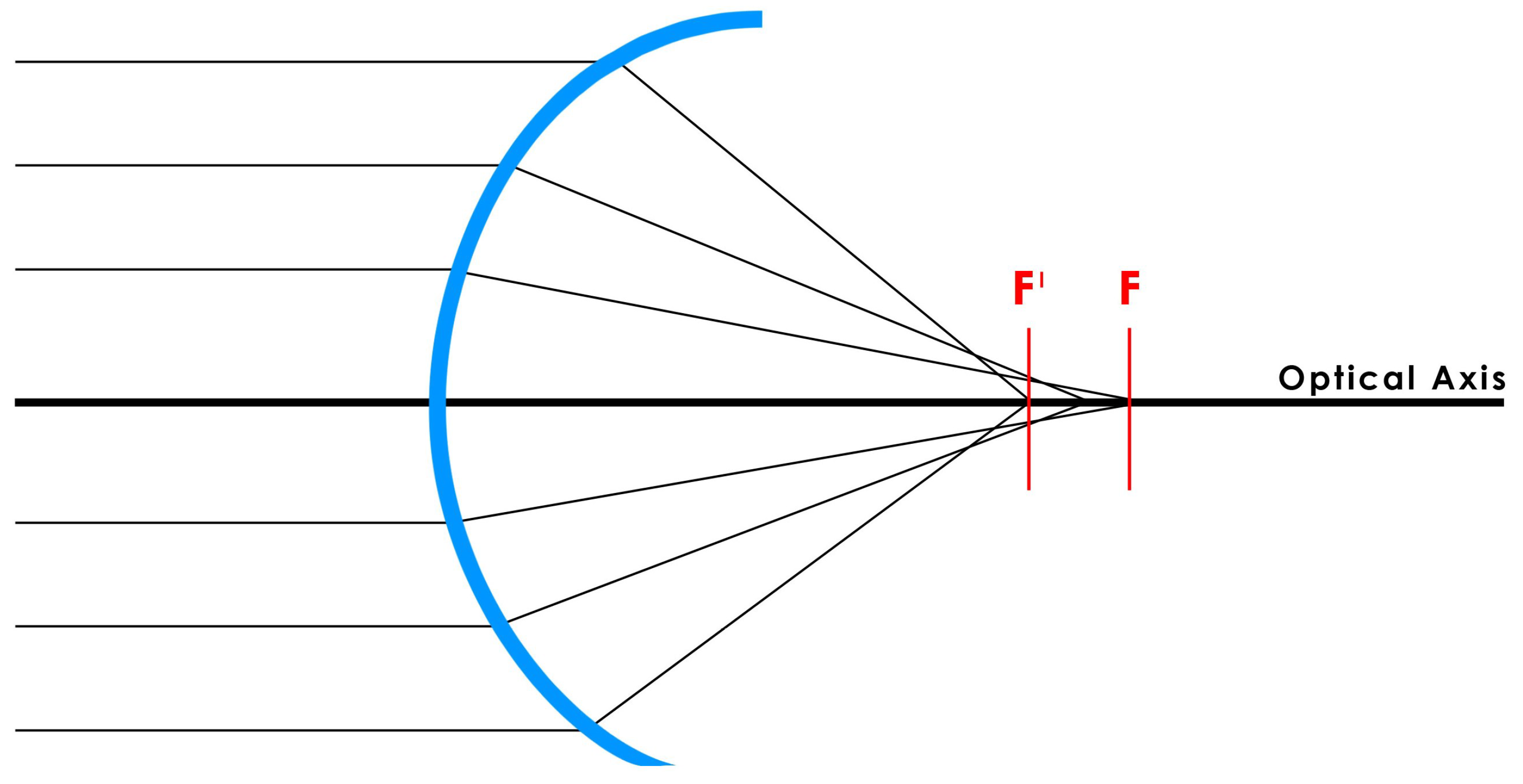
As with the mirror, the spherical diopter exhibits aberrations when light rays do not focus on a single point. As shown in Figure A9, the further away the incident rays are from the optical axis, the closer the point of focus is to the surface of the diopter. This is the reason for which the peripheral rays are said to focus before the paraxial rays, creating two different focal points. The distance between the two foci is called the spherical aberration of the diopter.
Figure A9. Schematic describing the spherical aberration of a diopter.
Jmmp 09 00105 g0a9
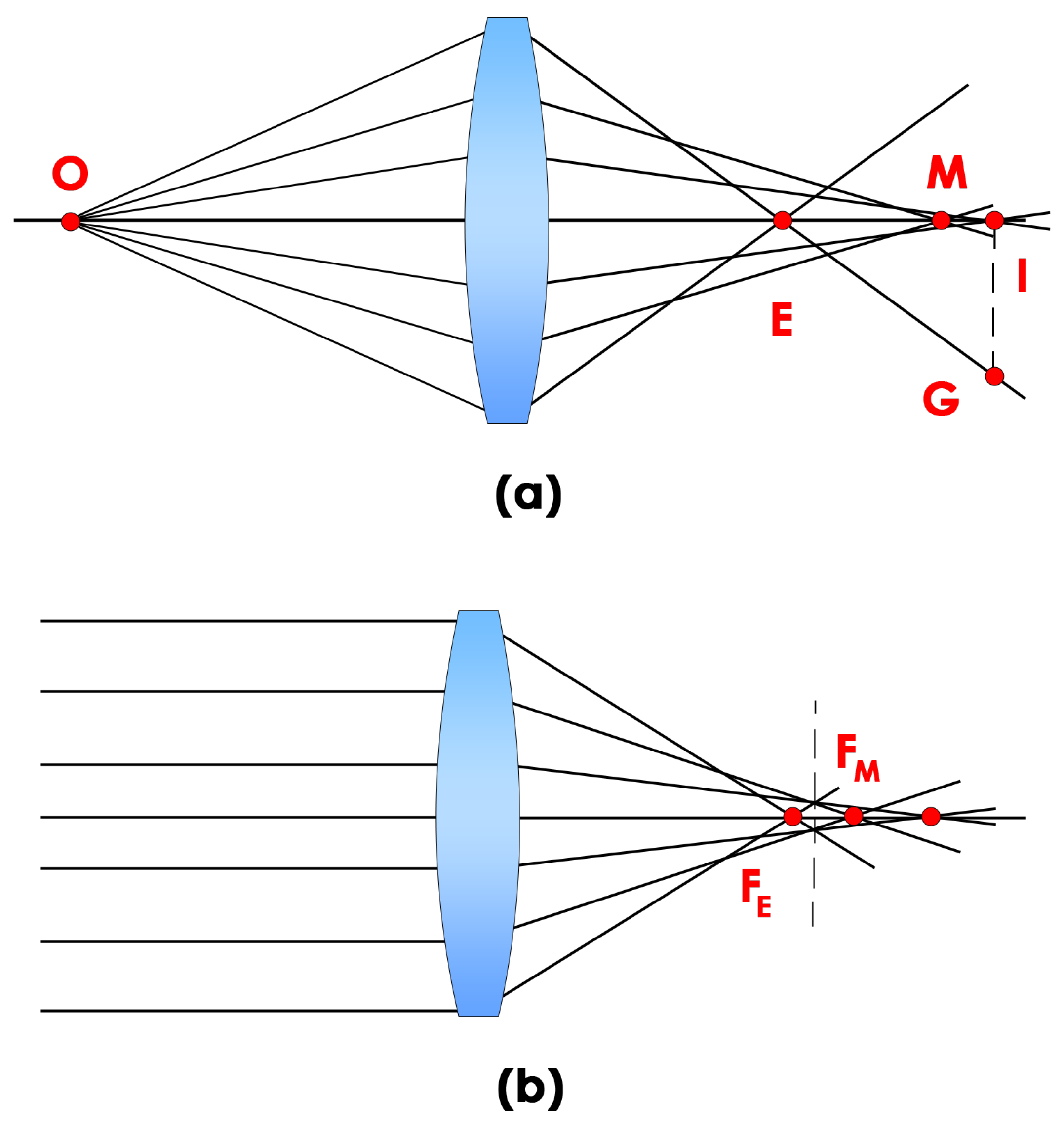
It is defined as positive when the peripheral rays focus before the paraxial ones and negative in the opposite case. In the former case, for example, the positive spherical aberration of the diopter has the peripheral rays focusing before the central ones. To eliminate this type of aberration, a surface should be constructed in which the curvature decreases from the center to the periphery, allowing for greater power at the center. Surfaces of this type are called prolate. The degree of prolate is determined on a case-by-case basis and depends primarily on both the refractive indices of the media under examination and the power of the diopter itself. For this reason, one can see how, if this characteristic is not precisely defined, new spherical aberrations can occur; for example, if an excessively prolate curve is made, a negative spherical aberration (opposite to the initial one) is obtained in which the paraxial rays will focus before the peripheral ones. The previous case can be extended by considering the union of two spherical diopters, resulting in the formation of a thin spherical lens. As in the previous case, light rays parallel to the optical axis create two different points of focus, a more distant one caused by the rays closer to the axis ( F M ) and one closer to the reference lens ( F E ) obtained from the outermost radii (Figure A10). The distance between these foci will take the name for spherical aberration of the lens.
Figure A10. Spherical aberration of a thin lens in the case of rays coming from an object and not parallel to the axis (a) and rays parallel to the axis (b). Figure adapted from Frank L Pedrotti, Leno M Pedrotti and Leno S Pedrotti. Introduction to Optics (Third Edition). Publisher: Addison-Wesley, Year: 2006, ISBN 9780131499331, p. 444 [101].
Jmmp 09 00105 g0a10
Spherical aberrations in diopters and thin lenses differ primarily in their origins and effects on optical performance. In diopters, spherical aberration is influenced by the eye’s accommodation, where primary spherical aberration decreases while secondary increases, leading to a net reduction of about 1/7 D per diopter of stimulus. In thin lenses, spherical aberration arises from the geometry of the lens surfaces; spherical lenses tend to focus light unevenly, causing peripheral rays to converge differently than central rays, resulting in blurriness. Aspherical designs can mitigate this issue by providing more uniform focus. Diopter aberrations, primarily affecting vision through corrective lenses, arise from the lens’s curvature and alignment. High-diopter lenses, such as +5, can lead to chromatic aberration if not properly aligned, causing focal axes to diverge and resulting in blurred images on the retina. Thin lenses, while simplifying calculations using the thin lens equation, are prone to spherical aberration due to varying light refraction at different lens points. This results in light rays not converging at a single focal point, contributing to image blurriness.
Specifically, Figure A10 depicts the case where rays from a point object are axial, i.e., positioned on the optical axis and not parallel to the axis, creating two image points, I and E, which are different because of the different origins of the rays; the distance between them provides the measure of longitudinal spherical aberration, while the distance I G measures the transverse spherical aberration. Like above, positive spherical aberration occurs if E lies to the left of I; on the contrary, the spherical aberration is negative [101]. It is possible to reduce spherical aberration in a lens by using, for example, a diaphragm to reduce the outermost rays on the lens, but this may also reduce the amount of light reaching the image.
Another effective method to reduce this phenomenon is the use of non-spherical lenses, known as aspherical lenses. Unlike spherical lenses, which have a uniformly curved surface, aspherical lenses have a surface that gradually varies in curvature along their surface (Figure A11).
Figure A11. Schematic difference between spherical (a) and aspherical lenses (b).
Jmmp 09 00105 g0a11
Transverse chromatic aberration (TCA) and longitudinal chromatic aberration (LCA) differ significantly in their visual impact. TCA causes color fringing around high-contrast edges, particularly noticeable in peripheral vision, where it degrades grating detection acuity more than central resolution (0.05 logMAR per arcmin peripherally vs. 0.03 logMAR centrally). LCA leads to colored areas in images due to different wavelengths focusing at varying distances along the optical axis, affecting overall image clarity. Both are assessed using specialized systems that quantify their effects on visual performance, including visual acuity and contrast sensitivity.
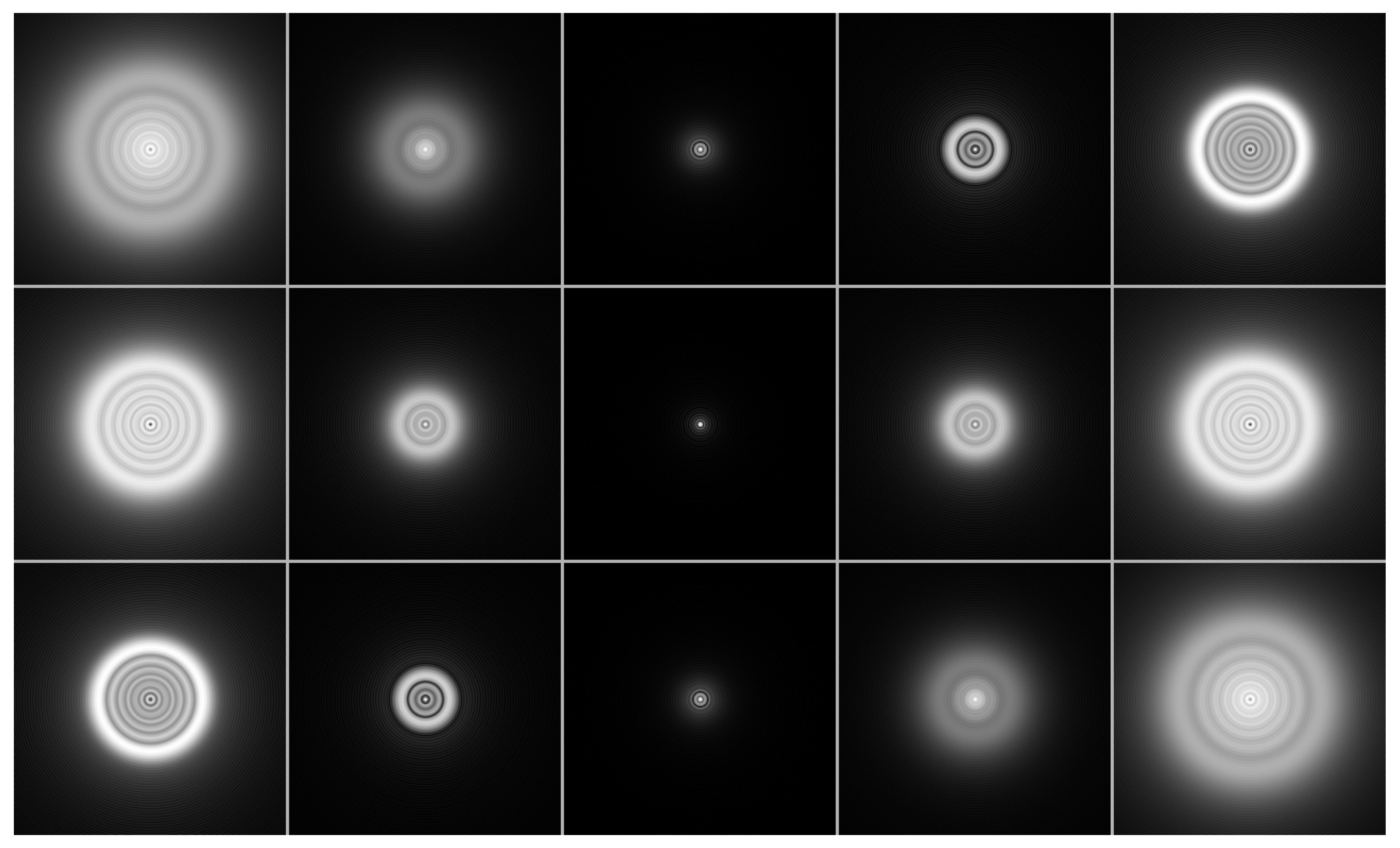
As an example, Figure A12 shows the case of a point source ‘photographed’ by an optical system subject to spherical aberrations: at the top, the optical image of the system with negative spherical aberration is shown, in the center, that of the system without spherical aberration, and at the bottom, it is the photo of the system with positive spherical aberration.
Figure A12. Simulation of a system with negative (top), zero (center) and positive (bottom) spherical aberration. Images to the left are defocused toward the inside; images on the right toward the outside. Image from https://commons.wikimedia.org/wiki/File:Spherical-aberration-disk.jpg (accessed on 21 February 2025) reused under the terms of Wikimedia Commons.
Jmmp 09 00105 g0a12
It can be seen that the images on the left show an inward blurring effect, while those on the right show an outward blurring effect. To mitigate longitudinal and transverse aberrations beyond using aperture and aspherical lenses, several techniques can be employed: (i) optimization of the lens shapes and configurations, utilizing hybrid elements and multiple lens components to address specific aberrations; (ii) incorporating low-dispersion glasses like extra-low dispersion (ED) glass to minimize chromatic aberration and improve image fidelity and (iii) implementing adaptive optics with deformable mirrors to correct aberrations dynamically in real-time.

Appendix A.1.5. Aberration of Coma

Coma is defined as “the variation in magnification with aperture”; the image formed by the paraxial rays has a different magnification than the image formed by the marginal rays. This is an aberration similar to spherical aberration but, in this case, the point object is not on the optical axis. The effect produced is characterized by an elongated image that shows a similarity to the shape of a comet, and hence the term ‘coma’. In other words, this effect occurs when the light rays coming from the object pass through an optical surface that is off-center on one side (i.e., when the point at which the maximum curvature occurs does not coincide with the optical axis), impinging on the focal plane at distinct points that differ from each other by a certain angle with respect to the axis of the system (Figure A13). Thus, coma can appear when parallel rays coming from a distant object form a certain angle θ with respect to the axis of a lens.
Figure A13. Schematic of the coma aberration.
Jmmp 09 00105 g0a13
The rays passing through the center of the lens are focused on the focal plane at a certain distance from the axis, while the peripheral rays are focused on different distances from the axis: in the case of when positive coma distances are greater, and vice versa in the case of negative coma. The superposition of these different rings of increasing size gives rise to a V-shape, similar to the crown of a comet (in Latin coma = crown), the tip of which points towards the axis of the optical system. It is customary to distinguish between tangential coma (T), which represents the total length of the blurring phenomenon, and sagittal coma ( S = T / 3 ), which constitutes the shaped part of a ‘V’ oriented towards the point image (Figure A14).
This happens in Newtonian telescopes where a parabolic mirror focuses parallel rays towards a specific focal point, while inclined rays are focused off-axis due to coma aberration. In practice, instead of a single curved focal surface, we have two of less-pronounced curvature coinciding only on the optical axis (Figure A14 and Figure A15).
Figure A14. Schematic description of difference between sagittal and tangential coma. Figure adapted from Joseph M Gear, Introduction to lens design, with practical ZEMAX examples. Publisher: Willmann-Bell; Year: 2002; ISBN 9780943396750 [102].
Jmmp 09 00105 g0a14
Figure A15. Coma aberration: Difference between sagittal and tangential planes.
Jmmp 09 00105 g0a15

Appendix A.1.6. Distortion

Distortion is defined as “a change in magnification along the image plane”. Thus, optical distortion occurs when the magnification of an extended object varies unevenly as its distance from the optical axis changes. Objects located at different distances from the axis may appear enlarged or shrunk differently from their actual size when reproduced through the optical system under examination. Specifically, when the distortion is positive, i.e., the magnification increases with increasing distance from the optical axis, we speak of “pincushion distortion”; conversely, when the distortion is negative and the magnification decreases with increasing distance from the axis, we speak of “barrel distortion” (Figure A16).
This type of aberration affects the shape of the image and its lateral position, but not its quality or sharpness, i.e., it does not affect the ability to discern details or the focus of the image, but rather alters the geometric representation of objects. Figure A16 shows how an object composed of a grid (Figure A16a) undergoes the phenomenon of distortion in two possible ways, distinguishing the pincushion distortion (Figure A16b) in which the magnification of the image increases with distance and manifests itself through an inward curvature of the lines in the center of the image, and from the barrel distortion (Figure A16c) in the opposite case.
Figure A16. Types of optical distortion from an extended object (a): pincushion distortion (b) and barrel distortion (c). Image adapted with permissions from www.vision-doctor.com.
Jmmp 09 00105 g0a16

Appendix A.1.7. Chromatic Aberration and Dispersion

In chromatic aberration, there are as many images of a polychromatic point source as there are monochromatic component lights. In the case of an extended object in white light, on the other hand, the image will show color smearing. This is a consequence of the fact that the refractive index of the system lenses, and thus also the focal length of the system itself, varies with the frequency for which the emerging rays converge at different points on the optical axis. To nullify the effect of this type of aberration, two thin lenses, suitably chosen according to the shape and quality of the glass that constitutes them, can be combined. We have already introduced the two types of chromatic aberration: (i) longitudinal chromatic aberration and (ii) lateral chromatic aberration. The longitudinal chromatic aberration (LCA or axial) occurs when different wavelengths do not converge at the same point after passing through an optical system (focus shift) (Figure A2a). In this case, given a white point source, in the plane close to the optical system, a blue-violet center image with a red contour is observed. Conversely, in the farthest plane from the center of the lens (i.e., where the red radiation is located), the central point is red and the halo is violet. Longitudinal aberration is defined as the distance between the two planes lying on the optical axis. Instead, the transverse chromatic aberration (TCA or lateral chromatic aberration) occurs when all wavelengths focus at different points but in the same focal plane (Figure A2b). One of the main differences between the two phenomena is that lateral chromatic aberration never occurs in the center of the image but in the corners and high-contrast areas. This phenomenon is often present in wide-angle lenses.
Finally, chromatic dispersion describes the variation in the refractive index at different wavelengths. The Abbe number ( ν value) is the parameter used to quantify this phenomenon for a specific material:
ν = n D 1 n F n C
where n D , n F and n C are, respectively, the refractive indices of the material at the wavelengths of the Fraunhofer spectral lines D (589.2 nm), F (486.1 nm) and C (656.3 nm). Therefore, a material characterized by a higher Abbe number has a lower color dispersion; conversely, a material characterized by a lower Abbe number has a higher color dispersion [103,104].
High Abbe numbers signify lower dispersion, making them ideal for applications like achromatic lenses, where minimizing chromatic aberration is crucial. Materials are categorized using the Abbe diagram, aiding in selecting appropriate glasses for optical designs. The Abbe diagram is a vital tool in lens design, providing insights into optical materials based on their refractive index and Abbe number. Its practical applications include to (i) help engineers choose glasses with appropriate dispersion characteristics for specific optical designs, minimizing chromatic aberration; (ii) aid in identifying combinations of materials that can cancel out aberrations, enhancing overall lens performance and (iii) facilitate the evaluation of lens configurations to achieve desired optical properties without extensive calculations or simulations. The Abbe diagram visually represents the relationship between the refractive index and the Abbe number of optical materials, categorizing them into types like crown and flint glasses. Dispersion describes how the refractive index varies with wavelength, impacting lens design and performance. Materials with low Abbe numbers exhibit high dispersion, while those with high values, such as crown glasses, show less. The Abbe number plays a crucial role in correcting the secondary spectrum in optical systems by quantifying the dispersion of materials. A higher Abbe number indicates lower dispersion, which helps in designing lenses that minimize chromatic aberration. In achromatic lenses, the condition ν 1 f 1 + ν 2 f 2 = 0 must be satisfied, where ν represents the Abbe number and f the focal lengths of two lens elements. This ensures that different wavelengths converge at the same point, effectively reducing secondary spectrum effects.

Appendix A.1.8. Curvature of Field

By definition, “field curvature is an extra-axial monochromatic aberration conjugated to astigmatism of oblique beams”. This type of aberration is precisely caused by the curved nature of the optical elements that project the image curved rather than flat (Figure A17). Despite the elimination of the astigmatism of oblique beams, the plane image of an object perpendicular to the optical axis is recreated on a curved surface, causing the system to be subject to curvature. The deviation induced by the curved plane is called field curvature, and results in a loss of sharpness of the final image particularly in the periphery because the light rays coming from the outer points converge on a different curve than the rays coming from the center of the object. Depending on the direction in which the light rays affect the focus, a distinction is made between tangential and sagittal field curvature. For example, in order to compensate for field curvature aberration, the 95 Megapixel CCD sensor of the Kepler Space Telescope (which has discovered several thousand planets outside the solar system) was constructed with a curved surface, thus adapting to the aberration of the optical system.
Figure A17. Schematic of the field curvature (a) and photo of the Kepler Space Telescope (b). Image from https://commons.wikimedia.org/wiki/File:Keplerspacecraft-FocalPlane-cutout.svg (accessed on 21 February 2025), courtesy of NASA.
Jmmp 09 00105 g0a17

References

  1. Salter, P.S.; Booth, M.J. Adaptive optics in laser processing. Light. Sci. Appl. 2019, 8, 110. [Google Scholar] [CrossRef] [PubMed]
  2. Park, K.; Yang, T.D.; Kim, H.J.; Kong, T.; Lee, J.M.; Choi, H.S.; Chun, H.J.; Kim, B.M.; Choi, Y. Inversion-free image recovery from strong aberration using a minimally sampled transmission matrix. Sci. Rep. 2019, 9, 1206. [Google Scholar] [CrossRef]
  3. Sawant, R.; Andrén, D.; Martins, R.J.; Khadir, S.; Verre, R.; Käll, M.; Genevet, P. Aberration-corrected large-scale hybrid metalenses. Optica 2021, 8, 1405. [Google Scholar] [CrossRef]
  4. Ho, A.H.; Kim, D.; Somekh, M.G. (Eds.) Handbook of Photonics for Biomedical Engineering; Springer: Dordrecht, The Netherlands, 2017. [Google Scholar] [CrossRef]
  5. Sirico, D.G.; Miccio, L.; Wang, Z.; Memmolo, P.; Xiao, W.; Che, L.; Xin, L.; Pan, F.; Ferraro, P. Compensation of aberrations in holographic microscopes: Main strategies and applications. Appl. Phys. B 2022, 128, 78. [Google Scholar] [CrossRef]
  6. Roorda, A. Adaptive optics for studying visual function: A comprehensive review. J. Vis. 2011, 11, 6. [Google Scholar] [CrossRef]
  7. Marcos, S.; Werner, J.S.; Burns, S.A.; Merigan, W.H.; Artal, P.; Atchison, D.A.; Hampson, K.M.; Legras, R.; Lundstrom, L.; Yoon, G.; et al. Vision science and adaptive optics, the state of the field. Vis. Res. 2017, 132, 3–33. [Google Scholar] [CrossRef]
  8. South, F.A.; Liu, Y.Z.; Bower, A.J.; Xu, Y.; Carney, P.S.; Boppart, S.A. Wavefront measurement using computational adaptive optics. J. Opt. Soc. Am. A 2018, 35, 466. [Google Scholar] [CrossRef]
  9. Baucom, D. The Adaptive Optics Revolution: A History (review). Technol. Cult. 2011, 52, 412–413. [Google Scholar] [CrossRef]
  10. Akyol, E.; Hagag, A.M.; Sivaprasad, S.; Lotery, A.J. Adaptive optics: Principles and applications in ophthalmology. Eye 2020, 35, 244–264. [Google Scholar] [CrossRef]
  11. Shemonski, N.D.; South, F.A.; Liu, Y.Z.; Adie, S.G.; Scott Carney, P.; Boppart, S.A. Computational high-resolution optical imaging of the living human retina. Nat. Photonics 2015, 9, 440–443. [Google Scholar] [CrossRef]
  12. Morgan, J.I.W.; Chui, T.Y.P.; Grieve, K. Twenty-five years of clinical applications using adaptive optics ophthalmoscopy [Invited]. Biomed. Opt. Express 2022, 14, 387. [Google Scholar] [CrossRef] [PubMed]
  13. Vacalebre, M.; Frison, R.; Corsaro, C.; Neri, F.; Conoci, S.; Anastasi, E.; Curatolo, M.C.; Fazio, E. Advanced Optical Wavefront Technologies to Improve Patient Quality of Vision and Meet Clinical Requests. Polymers 2022, 14, 5321. [Google Scholar] [CrossRef] [PubMed]
  14. Balas, M.; Ramalingam, V.; Pandya, B.; Abdelaal, A.; Shi, R.B. Adaptive optics imaging in ophthalmology: Redefining vision research and clinical practice. JFO Open Ophthalmol. 2024, 7, 100116. [Google Scholar] [CrossRef]
  15. Zhu, D.; Wang, R.; Žurauskas, M.; Pande, P.; Bi, J.; Yuan, Q.; Wang, L.; Gao, Z.; Boppart, S.A. Automated fast computational adaptive optics for optical coherence tomography based on a stochastic parallel gradient descent algorithm. Opt. Express 2020, 28, 23306. [Google Scholar] [CrossRef] [PubMed]
  16. Liu, Y.; Crowell, J.A.; Kurokawa, K.; Bernucci, M.T.; Ji, Q.; Lassoued, A.; Jung, H.W.; Keller, M.J.; Marte, M.E.; Miller, D.T. Ultrafast adaptive optics for imaging the living human eye. Nat. Commun. 2024, 15, 10409. [Google Scholar] [CrossRef]
  17. Zawadzki, R.J.; Jones, S.M.; Balderas-Mata, S.E.; Maliszewska, S.M.; Olivier, S.S.; Werner, J.S. Performance of 97-elements ALPAO membrane magnetic deformable mirror in Adaptive Optics—Optical Coherence Tomography system for in vivo imaging of human retina. Photonics Lett. Pol. 2011, 3, 147–149. [Google Scholar] [CrossRef]
  18. Zawadzki, R.J.; Jones, S.M.; Pilli, S.; Balderas-Mata, S.; Kim, D.Y.; Olivier, S.S.; Werner, J.S. Integrated adaptive optics optical coherence tomography and adaptive optics scanning laser ophthalmoscope system for simultaneous cellular resolution in vivo retinal imaging. Biomed. Opt. Express 2011, 2, 1674. [Google Scholar] [CrossRef]
  19. Evans, J.W.; Zawadzki, R.J.; Jones, S.M.; Olivier, S.S.; Werner, J.S. Error budget analysis for an Adaptive Optics Optical Coherence Tomography System. Opt. Express 2009, 17, 13768. [Google Scholar] [CrossRef]
  20. Li, K.Y.; Mishra, S.; Tiruveedhula, P.; Roorda, A. Comparison of control algorithms for a MEMS-based adaptive optics scanning laser ophthalmoscope. In Proceedings of the 2009 American Control Conference, St. Louis, MO, USA, 10–12 June 2009; pp. 3848–3853. [Google Scholar] [CrossRef]
  21. South, F.A.; Kurokawa, K.; Liu, Z.; Liu, Y.Z.; Miller, D.T.; Boppart, S.A. Combined hardware and computational optical wavefront correction. Biomed. Opt. Express 2018, 9, 2562. [Google Scholar] [CrossRef]
  22. Booth, M.J. Adaptive optical microscopy: The ongoing quest for a perfect image. Light. Sci. Appl. 2014, 3, e165. [Google Scholar] [CrossRef]
  23. Zinchik, A. Application of spatial light modulators for generation of laser beams with a spiral phase distribution. Sci. Tech. J. Inf. Technol. Mech. Opt. 2015, 15, 817–824. [Google Scholar] [CrossRef]
  24. Weiner, A.M. Femtosecond pulse shaping using spatial light modulators. Rev. Sci. Instrum. 2000, 71, 1929–1960. [Google Scholar] [CrossRef]
  25. Jullien, A. Spatial light modulators. Photoniques 2020, 101, 59–64. [Google Scholar] [CrossRef]
  26. Hutterer, V.; Ramlau, R.; Shatokhina, I. Real-time adaptive optics with pyramid wavefront sensors: Part I. A theoretical analysis of the pyramid sensor model. Inverse Probl. 2019, 35, 045007. [Google Scholar] [CrossRef]
  27. Anand, V.; Khonina, S.; Kumar, R.; Dubey, N.; Reddy, A.N.K.; Rosen, J.; Juodkazis, S. Three-Dimensional Incoherent Imaging Using Spiral Rotating Point Spread Functions Created by Double-Helix Beams [Invited]. Nanoscale Res. Lett. 2022, 17, 37. [Google Scholar] [CrossRef]
  28. Wang, K.; Yu, Y.; Preumont, A. Shape Control of a Unimorph Deformable Mirror for Space Active Optics under Uncertainties. Micromachines 2023, 14, 1756. [Google Scholar] [CrossRef] [PubMed]
  29. Simmonds, R.D.; Salter, P.S.; Jesacher, A.; Booth, M.J. Three dimensional laser microfabrication in diamond using a dual adaptive optics system. Opt. Express 2011, 19, 24122. [Google Scholar] [CrossRef]
  30. Yu, Z.; Li, H.; Zhong, T.; Park, J.H.; Cheng, S.; Woo, C.M.; Zhao, Q.; Yao, J.; Zhou, Y.; Huang, X.; et al. Wavefront shaping: A versatile tool to conquer multiple scattering in multidisciplinary fields. Innovation 2022, 3, 100292. [Google Scholar] [CrossRef]
  31. Kuang, Z.; Liu, D.; Perrie, W.; Edwardson, S.; Sharp, M.; Fearon, E.; Dearden, G.; Watkins, K. Fast parallel diffractive multi-beam femtosecond laser surface micro-structuring. Appl. Surf. Sci. 2009, 255, 6582–6588. [Google Scholar] [CrossRef]
  32. Schmiedl, R. Adaptive Optics for CO2 Laser Material Processing. In Adaptive Optics for Industry and Medicine, Proceedings of the 2nd International Workshop, University of Durham, UK, 12–16 July 1999; World Scientific: Singapore, 1999; pp. 32–36. [Google Scholar] [CrossRef]
  33. Kong, L.; Yang, K.; Su, C.; Guo, S.; Wang, S.; Cheng, T.; Yang, P. Adaptive Optics Tip-Tilt Correction Based on Smith Predictor and Filter-Optimized Linear Active Disturbance Rejection Control Method. Sensors 2023, 23, 6724. [Google Scholar] [CrossRef]
  34. Yang, H.; Tang, L.; Yan, Z.; Chen, P.; Yang, W.; Li, X.; Ge, Y. Wavefront Correction for Extended Sources Imaging Based on a 97-Element MEMS Deformable Mirror. Micromachines 2024, 16, 50. [Google Scholar] [CrossRef] [PubMed]
  35. Helmbrecht, M.A.; Besse, M.; Kempf, C.J.; He, M. Speed enhancements for a 489-actuator, piston-tip-tilt segment, MEMS DM system. In Proceedings of the Advanced Wavefront Control: Methods, Devices, and Applications VIII, San Diego, CA, USA, 1–5 August 2010; Dayton, D.C., Rhoadarmer, T.A., Sanchez, D.J., Eds.; SPIE: Bremerhaven, Germany, 2010; Volume 7816, p. 78160F. [Google Scholar] [CrossRef]
  36. Iyer, R.R.; Liu, Y.Z.; Boppart, S.A. Automated sensorless single-shot closed-loop adaptive optics microscopy with feedback from computational adaptive optics. Opt. Express 2019, 27, 12998. [Google Scholar] [CrossRef]
  37. Rigaut, F.J.; Ellerbroek, B.L.; Flicker, R. Principles, limitations, and performance of multiconjugate adaptive optics. In Proceedings of the Adaptive Optical Systems Technology, Munich, Germany, 27 March–1 April 2000; Wizinowich, P.L., Ed.; SPIE: Bremerhaven, Germany, 2000; Volume 4007, pp. 1022–1031. [Google Scholar] [CrossRef]
  38. Polans, J.; Cunefare, D.; Cole, E.; Keller, B.; Mettu, P.S.; Cousins, S.W.; Allingham, M.J.; Izatt, J.A.; Farsiu, S. Enhanced visualization of peripheral retinal vasculature with wavefront sensorless adaptive optics optical coherence tomography angiography in diabetic patients. Opt. Lett. 2016, 42, 17. [Google Scholar] [CrossRef]
  39. Durech, E.; Newberry, W.; Franke, J.; Sarunic, M.V. Wavefront sensor-less adaptive optics using deep reinforcement learning. Biomed. Opt. Express 2021, 12, 5423. [Google Scholar] [CrossRef]
  40. Rimmele, T.R.; Marino, J. Solar Adaptive Optics. Living Rev. Sol. Phys. 2011, 8, 2. [Google Scholar] [CrossRef] [PubMed]
  41. Stuart, B.C.; Feit, M.D.; Herman, S.; Rubenchik, A.M.; Shore, B.W.; Perry, M.D. Nanosecond-to-femtosecond laser-induced breakdown in dielectrics. Phys. Rev. B 1996, 53, 1749–1761. [Google Scholar] [CrossRef]
  42. Schaffer, C.B.; Brodeur, A.; Mazur, E. Laser-induced breakdown and damage in bulk transparent materials induced by tightly focused femtosecond laser pulses. Meas. Sci. Technol. 2001, 12, 1784–1794. [Google Scholar] [CrossRef]
  43. Tan, D.; Sharafudeen, K.N.; Yue, Y.; Qiu, J. Femtosecond laser induced phenomena in transparent solid materials: Fundamentals and applications. Prog. Mater. Sci. 2016, 76, 154–228. [Google Scholar] [CrossRef]
  44. Hnatovsky, C.; Taylor, R.; Simova, E.; Rajeev, P.; Rayner, D.; Bhardwaj, V.; Corkum, P. Fabrication of microchannels in glass using focused femtosecond laser radiation and selective chemical etching. Appl. Phys. A 2006, 84, 47–61. [Google Scholar] [CrossRef]
  45. Bisch, N.; Guan, J.; Booth, M.J.; Salter, P.S. Adaptive optics aberration correction for deep direct laser written waveguides in the heating regime. Appl. Phys. A 2019, 125, 364. [Google Scholar] [CrossRef]
  46. Kratz, M.; Rückle, L.; Kalupka, C.; Reininghaus, M.; Haefner, C.L. Dynamic correction of optical aberrations for height-independent selective laser induced etching processing strategies. Opt. Express 2023, 31, 26104. [Google Scholar] [CrossRef] [PubMed]
  47. Hasegawa, S.; Hayasaki, Y. Femtosecond laser processing with adaptive optics based on convolutional neural network. Opt. Lasers Eng. 2021, 141, 106563. [Google Scholar] [CrossRef]
  48. Gatinel, D.; Rampat, R.; Malet, J.; Dumas, L. Wavefront sensing, novel lower degree/higher degree polynomial decomposition and its recent clinical applications: A review. Indian J. Ophthalmol. 2020, 68, 2670. [Google Scholar] [CrossRef]
  49. Dumas, L.; Gatinel, D.; Malet, J. A New Decomposition Basis for The Classification of Aberrations of The Human Eye. ESAIM: Proc. Surv. 2018, 62, 43–55. [Google Scholar] [CrossRef]
  50. Malinauskas, M.; Žukauskas, A.; Hasegawa, S.; Hayasaki, Y.; Mizeikis, V.; Buividas, R.; Juodkazis, S. Ultrafast laser processing of materials: From science to industry. Light. Sci. Appl. 2016, 5, e16133. [Google Scholar] [CrossRef] [PubMed]
  51. Weber, R.; Graf, T. The challenges of productive materials processing with ultrafast lasers. Adv. Opt. Technol. 2021, 10, 239–245. [Google Scholar] [CrossRef]
  52. Sugioka, K.; Cheng, Y. Ultrafast lasers—Reliable tools for advanced materials processing. Light. Sci. Appl. 2014, 3, e149. [Google Scholar] [CrossRef]
  53. Feng, J.; Wang, J.; Liu, H.; Sun, Y.; Fu, X.; Ji, S.; Liao, Y.; Tian, Y. A Review of an Investigation of the Ultrafast Laser Processing of Brittle and Hard Materials. Materials 2024, 17, 3657. [Google Scholar] [CrossRef]
  54. Beck, R.J. Adaptive Optics for Laser Processing. Ph.D. Thesis, Heriot-Watt University, Edinburgh, Scotland, 2011. [Google Scholar]
  55. Parry, J.; Beck, R.; Weston, N.; Shephard, J.; Hand, D. Application of adaptive optics to laser micromachining. In Proceedings of the International Congress on Applications of Lasers & Electro-Optics. Laser Institute of America, Anaheim, CA, USA, 26–30 September 2010; pp. 767–776. [Google Scholar] [CrossRef]
  56. Schmidt, M.; Cvecek, K.; Duflou, J.; Vollertsen, F.; Arnold, C.; Matthews, M. Dynamic beam shaping—Improving laser materials processing via feature synchronous energy coupling. CIRP Ann. 2024, 73, 533–559. [Google Scholar] [CrossRef]
  57. Wang, X.; Zhu, L.; Zhang, Q.; Yang, L.; Tang, M.; Xiao, F.; Wang, X.; Shen, S.; Zhang, L.; Guo, Y. Femtosecond laser processing with aberration correction based on Shack-Hartmann wavefront sensor. Opt. Lasers Eng. 2025, 184, 108693. [Google Scholar] [CrossRef]
  58. Salter, P.S.; Booth, M.J. Focussing over the edge: Adaptive subsurface laser fabrication up to the sample face. Opt. Express 2012, 20, 19978. [Google Scholar] [CrossRef] [PubMed]
  59. Stallinga, S. Axial birefringence in high-numerical-aperture optical systems and the light distribution close to focus. J. Opt. Soc. Am. A 2001, 18, 2846. [Google Scholar] [CrossRef]
  60. Zhou, G.; Jesacher, A.; Booth, M.; Wilson, T.; Ródenas, A.; Jaque, D.; Gu, M. Axial birefringence induced focus splitting in lithium niobate. Opt. Express 2009, 17, 17970. [Google Scholar] [CrossRef] [PubMed]
  61. Karpinski, P.; Shvedov, V.; Krolikowski, W.; Hnatovsky, C. Laser-writing inside uniaxially birefringent crystals: Fine morphology of ultrashort pulse-induced changes in lithium niobate. Opt. Express 2016, 24, 7456. [Google Scholar] [CrossRef] [PubMed]
  62. Metel, A.; Stebulyanin, M.; Fedorov, S.; Okunkova, A. Power Density Distribution for Laser Additive Manufacturing (SLM): Potential, Fundamentals and Advanced Applications. Technologies 2018, 7, 5. [Google Scholar] [CrossRef]
  63. Kato, J.i.; Takeyasu, N.; Adachi, Y.; Sun, H.B.; Kawata, S. Multiple-spot parallel processing for laser micronanofabrication. Appl. Phys. Lett. 2005, 86, 044102. [Google Scholar] [CrossRef]
  64. Cumming, B.P.; Debbarma, S.; Luther-Davis, B.; Gu, M. Simultaneous compensation for aberration and axial elongation in three-dimensional laser nanofabrication by a high numerical-aperture objective. Opt. Express 2013, 21, 19135. [Google Scholar] [CrossRef]
  65. Li, S.; Zhou, L.; Cui, C.; Wang, K.; Yan, X.; Wang, Y.; Ding, L.; Wang, Y.; Lu, Z. Wavefront Shaping by a Small-Aperture Deformable Mirror in the Front Stage for High-Power Laser Systems. Appl. Sci. 2017, 7, 379. [Google Scholar] [CrossRef]
  66. Campbell, S.; Triphan, S.M.F.; El-Agmy, R.; Greenaway, A.H.; Reid, D.T. Direct optimization of femtosecond laser ablation using adaptive wavefront shaping. J. Opt. A Pure Appl. Opt. 2007, 9, 1100–1104. [Google Scholar] [CrossRef]
  67. Lin, V.; Wei, H.C.; Hsieh, H.T.; Su, G.D.J. An Optical Wavefront Sensor Based on a Double Layer Microlens Array. Sensors 2011, 11, 10293–10307. [Google Scholar] [CrossRef]
  68. Wei, X.; Jing, J.C.; Shen, Y.; Wang, L.V. Harnessing a multi-dimensional fibre laser using genetic wavefront shaping. Light. Sci. Appl. 2020, 9, 149. [Google Scholar] [CrossRef] [PubMed]
  69. Williams, W.H.; Auerbach, J.M.; Henesian, M.A.; Lawson, J.K.; Hunt, J.T.; Sacks, R.A.; Widmayer, C.C. Modeling characterization of the National Ignition Facility focal spot. In Proceedings of the High-Power Lasers, San Jose, CA, USA, 24–30 January 1998; Basu, S., Ed.; SPIE: Bremerhaven, Germany, 1998; Volume 3264, p. 93. [Google Scholar] [CrossRef]
  70. Haber, A.; Polo, A.; Smith, C.S.; Pereira, S.F.; Urbach, P.; Verhaegen, M. Iterative learning control of a membrane deformable mirror for optimal wavefront correction. Appl. Opt. 2013, 52, 2363. [Google Scholar] [CrossRef]
  71. Jia, X.; Fu, Y.; Li, K.; Wang, C.; Li, Z.; Wang, C.; Duan, J. Burst Ultrafast Laser Welding of Quartz Glass. Materials 2025, 18, 1169. [Google Scholar] [CrossRef] [PubMed]
  72. Cheng, H.; Xia, C.; Kuebler, S.M.; Golvari, P.; Sun, M.; Zhang, M.; Yu, X. Generation of Bessel-beam arrays for parallel fabrication in two-photon polymerization. J. Laser Appl. 2021, 33, 012040. [Google Scholar] [CrossRef]
  73. Balage, P.; Guilberteau, T.; Lafargue, M.; Bonamis, G.; Hönninger, C.; Lopez, J.; Manek-Hönninger, I. Bessel Beam Dielectrics Cutting with Femtosecond Laser in GHz-Burst Mode. Micromachines 2023, 14, 1650. [Google Scholar] [CrossRef]
  74. Guilberteau, T.; Balage, P.; Lafargue, M.; Lopez, J.; Gemini, L.; Manek-Hönninger, I. Bessel Beam Femtosecond Laser Interaction with Fused Silica Before and After Chemical Etching: Comparison of Single Pulse, MHz-Burst, and GHz-Burst. Micromachines 2024, 15, 1313. [Google Scholar] [CrossRef]
  75. Helmy, A.K.; El-Taweel, G.S. Image segmentation scheme based on SOM-PCNN in frequency domain. Appl. Soft Comput. 2016, 40, 405–415. [Google Scholar] [CrossRef]
  76. Xu, X.; Liang, T.; Wang, G.; Wang, M.; Wang, X. Self-Adaptive PCNN Based on the ACO Algorithm and its Application on Medical Image Segmentation. Intell. Autom. Soft Comput. 2016, 23, 303–310. [Google Scholar] [CrossRef]
  77. Suárez Gómez, S.L.; García Riesgo, F.; González Gutiérrez, C.; Rodríguez Ramos, L.F.; Santos, J.D. Defocused Image Deep Learning Designed for Wavefront Reconstruction in Tomographic Pupil Image Sensors. Mathematics 2020, 9, 15. [Google Scholar] [CrossRef]
  78. Nazir, S.; Vaquero, L.; Mucientes, M.; Brea, V.M.; Coltuc, D. Depth Estimation and Image Restoration by Deep Learning From Defocused Images. IEEE Trans. Comput. Imaging 2023, 9, 607–619. [Google Scholar] [CrossRef]
  79. Li, A.; Singh, S.; Sievenpiper, D. Metasurfaces and their applications. Nanophotonics 2018, 7, 989–1011. [Google Scholar] [CrossRef]
  80. Yang, Y.; Seong, J.; Choi, M.; Park, J.; Kim, G.; Kim, H.; Jeong, J.; Jung, C.; Kim, J.; Jeon, G.; et al. Integrated metasurfaces for re-envisioning a near-future disruptive optical platform. Light. Sci. Appl. 2023, 12, 152. [Google Scholar] [CrossRef] [PubMed]
  81. Caputo, R.; Ferraro, A. Metasurfaces: Theoretical Basis and Application Overview. In Hybrid Flatland Metastructures; AIP Publishing LLC: Melville, NY, USA, 2021; pp. 1–20. [Google Scholar] [CrossRef]
  82. Chen, M.K.; Wu, Y.; Feng, L.; Fan, Q.; Lu, M.; Xu, T.; Tsai, D.P. Principles, Functions, and Applications of Optical Meta-Lens. Adv. Opt. Mater. 2021, 9, 2001414. [Google Scholar] [CrossRef]
  83. Jung, J.; Kim, H.; Shin, J. Three-dimensionally reconfigurable focusing of laser by mechanically tunable metalens doublet with built-in holograms for alignment. Nanophotonics 2023, 12, 1373–1385. [Google Scholar] [CrossRef] [PubMed]
  84. She, A.; Zhang, S.; Shian, S.; Clarke, D.R.; Capasso, F. Adaptive metalenses with simultaneous electrical control of focal length, astigmatism, and shift. Sci. Adv. 2018, 4, eaap9957. [Google Scholar] [CrossRef]
  85. Li, X.; Cai, X.; Liu, C.; Kim, Y.; Badloe, T.; Liu, H.; Rho, J.; Xiao, S. Cascaded metasurfaces enabling adaptive aberration corrections for focus scanning. Opto-Electron. Adv. 2024, 7, 240085. [Google Scholar] [CrossRef]
  86. Kamali, S.M.; Arbabi, E.; Arbabi, A.; Faraon, A. Conformal optical metasurfaces. U.S. Patent 20160320531A1, 12 June 2016. [Google Scholar]
  87. Chen, R.; Chang, S.; Lei, S. An Exploratory Study of Laser Scribing Quality through Cross-Section Scribing Profiles. Micromachines 2023, 14, 2020. [Google Scholar] [CrossRef]
  88. Shitrit, N. Surface-emitting lasers meet metasurfaces. Light. Sci. Appl. 2024, 13, 37. [Google Scholar] [CrossRef]
  89. Hudec, R.; Spurny, M.; Krizek, M.; Pata, P.; Slosiar, R.; Rerabek, M.; Klima, M. Detection of GRBs and OTs by All-Sky Optical and SID Monitors. Adv. Astron. 2010, 2010, 428943. [Google Scholar] [CrossRef]
  90. Luo, J.; Nie, Y.; Ren, W.; Cao, X.; Yang, M.H. Correcting Optical Aberration via Depth-Aware Point Spread Functions. IEEE Trans. Pattern Anal. Mach. Intell. 2024, 46, 5541–5555. [Google Scholar] [CrossRef]
  91. Cao, Y.; Lu, Y.; Feng, P.; Qiao, X.; Ordones, S.; Su, R.; Wang, X. Distortion measurement of a lithography projection lens based on multichannel grating lateral shearing interferometry. Appl. Opt. 2024, 63, 2056. [Google Scholar] [CrossRef] [PubMed]
  92. Cunha, M.O.T.; Padua, S.; Walborn, S.; Monken, C. Quantum Erasure. Am. Sci. 2003, 91, 336. [Google Scholar] [CrossRef]
  93. van den Bos, A. Rayleigh wave-front criterion: Comment. J. Opt. Soc. Am. A 1999, 16, 2307. [Google Scholar] [CrossRef]
  94. Chen, L.; Singer, B.; Guirao, A.; Porter, J.; Williams, D.R. Image Metrics for Predicting Subjective Image Quality. Optom. Vis. Sci. 2005, 82, 358–369. [Google Scholar] [CrossRef]
  95. Hecht, E. Optics, 5th ed.; global edition ed.; Pearson Education, Inc.: Boston, MA, USA, 2017. [Google Scholar]
  96. Rojo, P.; Royo, S.; Ramírez, J.; Madariaga, I. Numerical implementation of generalized Coddington equations for ophthalmic lens design. J. Mod. Opt. 2014, 61, 204–214. [Google Scholar] [CrossRef]
  97. Liu, T.; Thibos, L.N. Compensation of corneal oblique astigmatism by internal optics: A theoretical analysis. Ophthalmic Physiol. Opt. 2017, 37, 305–316. [Google Scholar] [CrossRef]
  98. Welford, W.T. Aberrations of Optical Systems; Routledge: England, UK, 2017. [Google Scholar] [CrossRef]
  99. Freeman, M.; Hull, C. Optics; Butterworth-Heinemann: Oxford, UK, 2003; p. 576. [Google Scholar]
  100. Liu, T.; Thibos, L.N. Variation of axial and oblique astigmatism with accommodation across the visual field. J. Vis. 2017, 17, 24. [Google Scholar] [CrossRef]
  101. Pedrotti, F.; Pedrotti, L.; Pedrotti, L. Introduction to Optics, 3rd ed.; Addison-Wesley: Boston, MA, USA, 2006. [Google Scholar]
  102. Geary, J. Introduction to Lens Design: With Practical ZEMAX Examples; Willmann-Bell: Richmond, VA, USA, 2002. [Google Scholar]
  103. Kato, N.; Ikeda, S.; Hirakawa, M.; Ito, H. Correlation of the Abbe Number, the Refractive Index, and Glass Transition Temperature to the Degree of Polymerization of Norbornane in Polycarbonate Polymers. Polymers 2020, 12, 2484. [Google Scholar] [CrossRef]
  104. Zhao, H.; Mainster, M.A. The effect of chromatic dispersion on pseudophakic optical performance. Br. J. Ophthalmol. 2007, 91, 1225–1229. [Google Scholar] [CrossRef]
Figure 1. Hybrid lens-metacorrector for chromatic (a) and spherical (b) aberration correction. Experimental and simulated polarization conversion efficiencies (c) for Pancharatnam–Berry phase nanopillars constituting the large-area metasurfaces displayed in the SEM image (d). Phase outcomes for chromatic (e) and spherical (f) aberration correction metasurface and corresponding measured and calculated radially averaged phase profile (g,h). Figure reprinted from ref. [3] under the terms of the OSA Open Access Publishing Agreement.
Jmmp 09 00105 g001
Figure 2. Example of adaptive optics setup used in ophthalmology for measuring and correcting aberration of the human eye (A). Photoreceptor mosaic pictures of a normal-sighted eye showing the difference without (B1) and with (B2) the use of adaptive optics. Figure reprinted from ref. [12] under the terms of the Optica Open Access Publishing Agreement.
Jmmp 09 00105 g002
Figure 3. Examples of AO systems with the same elements but using one (a) or two (b) different types of deformable mirrors (DMs). Figure adapted from ref. [17] under the terms of the Creative Commons Attribution License.
Jmmp 09 00105 g003
Figure 4. Optical vortex beam generated from a spiral phase pattern through SLM [23] (top). Temporal shaping of a femtosecond laser pulse due to the insertion of an SLM in a zero-dispersion line [24] (bottom). Figure reprinted from ref. [25] under the terms of the Creative Commons Attribution License.
Jmmp 09 00105 g004
Figure 5. Schematic representation of working principle and optical setup of the Shack–Hartmann (a) and pyramid (b) sensors, reprinted from https://commons.wikimedia.org/wiki/File:Shack_hartmann.jpg (accessed on 21 February 2025) under the terms of the CC BY-SA 3.0 license and from ref. [26] under the terms of the Creative Commons Attribution 3.0 license, respectively.
Jmmp 09 00105 g005
Figure 6. Schematic representation of working principle and optical setup of a spatial light modulator (a) and deformable mirror (b), reprinted under the terms of the CC-BY license from refs. [27] and [28], respectively.
Jmmp 09 00105 g006
Figure 7. Optical setup of the AO tip–tilt correction system. Figure reprinted from ref. [33] under the terms of the CC-BY license.
Jmmp 09 00105 g007
Figure 8. Picture of an MEMS deformable mirror (a) and corresponding spatial distribution of the 97 actuators (b). Figure reprinted from ref. [34] under the terms of the CC-BY license.
Jmmp 09 00105 g008
Figure 10. Pristine and etched modifications for microscope objective-corrected aberration at a 1.1 mm depth (green), maximum aberrated case in 11.8 mm depth (red) and SLM-corrected aberration case (blue) to demonstrate pulse energy conservation and uniform etch channel precision in laser propagation direction for all glass thicknesses. Figure reprinted from ref. [46] under the terms of the OSA Open Access Publishing Agreement.
Jmmp 09 00105 g010
Figure 12. Schematic of a wavefront shaping system. Image from Sensen Li et al. [65] under the terms of the CC-BY license.
Jmmp 09 00105 g012
Figure 13. (A) Starting metasurface lens made by discrete cells, each containing a metasurface element able to convey the proper phase shift to the incident light to remodel the wavefront (dashed line: optical axis) and the beam shape. (B) Metasurface lens with uniform and isotropic stretch for correcting defocus. (C) Metasurface lens under asymmetric stretch for correcting astigmatism. (D) Metasurface lens moved laterally in the x,y plane for correcting shift. (E) Schematic of the device constituted by a metalens and a dielectric elastomer actuator with five addressable electrodes able to define the strain field of the metasurface. Figures reprinted from ref. [84] under the terms of the CC BY license.
Jmmp 09 00105 g013
Figure 14. Schematic of the cascaded metasurfaces made by two rotated layers (angle α 1 and α 2 ) of transparent metasurfaces (a). Picture of fabricated meta-device with two-layer all-silicon metasurfaces fixed in a motorized rotation stage and SEM image of the metasurface (b,c). Figures reprinted from ref. [85] under the terms of the CC BY license.
Jmmp 09 00105 g014
Disclaimer/Publisher’s Note: The statements, opinions and data contained in all publications are solely those of the individual author(s) and contributor(s) and not of MDPI and/or the editor(s). MDPI and/or the editor(s) disclaim responsibility for any injury to people or property resulting from any ideas, methods, instructions or products referred to in the content.