Abstract
In the context of growing environmental concerns and the demand for more sustainable manufacturing practices, this study evaluates the environmental and economic performance of two production routes for a stainless steel support block used in steel mills. A comparative Life Cycle Assessment (LCA) and Life Cycle Costing (LCC) were conducted to assess a conventional subtractive manufacturing process based on Computer Numerical Control (CNC) machining versus a hybrid approach that combines Plasma Arc-Wire Arc Additive Manufacturing (PA-WAAM) with CNC finishing. The LCA was carried out using ReCiPe 2016 Midpoint and Endpoint methodologies in SimaPro, while the LCC employed a cradle-to-gate cost model. Results showed that the hybrid WAAM-CNC route reduced average environmental impacts by 49% across 18 categories and decreased steel consumption by approximately 70% due to near-net-shape fabrication. Although the hybrid method incurred an approximate 3.5 times increase in unit production cost, this was primarily attributed to equipment investment. In contrast, operational costs such as labor, materials, and consumables were significantly lower—by 66%, 28%, and 45%, respectively. These findings support the hybrid approach as a more sustainable manufacturing alternative with the potential for long-term cost optimization as additive technologies mature.
1. Introduction
Natural resources have played an important role in human civilization, but the Industrial Revolution marked a turning point, significantly speeding up resource consumption, a trend that continues today. In recent decades, global material extraction has witnessed a significant rise; specifically, the demand for metal ores has more than doubled since 1980. This tendency, closely aligned with global economic growth, experienced a notable upsurge around 2002, driven by the resource-intensive development of emerging economies and increased consumption in developed nations [1]. In 2021, the manufacturing industry was responsible for 25% of global energy consumption, 40% of global material usage, and 20% of global CO2 emissions. Reducing these environmental impacts is highly important for global sustainability [2]. As the steel demand is projected to increase, aligning the industry’s decarbonization efforts with the Paris Agreement’s net-zero emissions goal poses a significant challenge [3]. The European Union (EU), the world’s second-largest steel producer, contributes nearly 11% of the global steel output. Within the EU, Germany leads in value-added manufacturing of basic metals (including iron and steel) and fabricated metal products [4].
As outlined above, the metal components manufacturing sector significantly contributes to the industry’s overall environmental impact. Subtractive Manufacturing (SM) and Additive Manufacturing (AM) are two fundamental manufacturing processes for producing steel components. While SM remains dominant, AM has emerged as a promising alternative for certain applications [5]. These two manufacturing processes differ significantly in their approach. AM builds up parts layer by layer, adding material to achieve the desired shape. In contrast, SM removes material from a solid block to attain the final form [6]. SM, especially Computer Numerical Control (CNC) machining, excels in the mass production of standardized parts with higher solid-envelope ratios (i.e., the ratio of the final part’s solid volume to the volume of its enclosing geometry or bounding box). Conversely, AM is well-suited for producing complex, customized parts, often with lower solid-envelope ratios, and is particularly prevalent in industries like aerospace, healthcare, and automotive, allowing decentralized production by using the networking potential to connect numerous machines simultaneously [7]. In many cases, AM-manufactured parts often require subtractive techniques to ensure geometric tolerance and remove support materials [8]. To achieve the desired final product by CNC machining, a process plan is developed to outline the specific milling operations [9]. Once the process plan is finalized, machining operations commence. Upon completion, rigorous quality control procedures are implemented to identify and rectify any defects or non-conformities [10]. However, this manufacturing process implies an important amount of metal waste.
To remain competitive, industries must adapt to emerging manufacturing trends and meet increasingly rigorous environmental standards. Industry 4.0, characterized by the integration of advanced technologies and intelligent systems [11], is driving this transformation alongside AM technologies. In this context, Wire Arc Additive Manufacturing (WAAM) particularly stands out for its diverse applications across several industrial sectors [12]. While solid-state AM methods such as additive friction stir deposition [13], ultrasonic additive manufacturing [14] and cold spray additive manufacturing [15] offer excellent properties and results, WAAM provides greater flexibility in material selection and design complexity. WAAM is a direct energy deposition process that utilizes an arc welding source to continuously melt and deposit filler material in the form of wire [16]. This method allows layer-by-layer fabrication of 3D parts, virtually unlimited in size at high deposition rates [17,18]. WAAM’s high deposition rates make it ideal for producing large metallic components, particularly those with high material utilization ratios [19]. This can lead to significant material savings, reducing material consumption by 35–65% compared to traditional manufacturing processes like milling and turning [20]. Moreover, its ability to fabricate complex 3D structures has attracted considerable interest from researchers, manufacturers, and consumers compared to alternative fusion processes [21].
Although all types of WAAM hardware systems operate on the principle of melting and depositing material via a heat source, significant variations exist. These include the employed heat source (electric arc or laser), the feedstock material (wire or powder), the deposition rate, achievable build geometry, the resulting surface finish, and associated costs. A detailed description of each process is provided in the reference [22]. Among them is the particularly noteworthy plasma-based WAAM, a process that utilizes a plasma arc to melt and deposit wire-form filler material [23]. Compared to those based on an electric arc, such as the Gas Tungsten Arc process (GTA), plasma arcs offer significant advantages in terms of reduced welding distortions and heat-affected zones [24]. Plasma’s higher energy density, improved arc stability, and lower inclusion levels enable higher travel speeds while maintaining superior part quality [25]. Therefore, to accurately assess the material savings and environmental benefits of this AM technology in industrial part production, a life cycle assessment (LCA) is required.
LCA has emerged as a powerful tool for evaluating the environmental impacts of products and services throughout their entire life cycle, from raw material extraction to end-of-life disposal [26]. Its origins can be traced back to the 1960s when growing concerns about resource depletion and energy consumption spurred the development of methods to assess energy usage and predict future resource availability [27]. Since the turn of the 21st century, LCA has experienced significant growth, driven by advancements in qualitative frameworks, impact assessment methodologies, and data quality. While the 2000s marked a decade of significant development and refinement in LCA practices, today, this methodology is widely adopted across a wide range of manufacturing sectors, including metals [28], polymers [29], composites [30], and coatings [31], among others. It has become an indispensable tool for informed decision-making [32].
References to the application of LCA methodology to assess the benefits of WAAM technology can be found in the literature. Reis et al. ([22]) conducted a practical study involving the production of three metal parts of varying complexity utilizing both WAAM and CNC processes. Their study revealed that the WAAM method saved between 40% and 70% of the material and reduced the environmental impact by 12% to 47% compared to the subtractive method for manufacturing the three geometries under study. Bekker et al. ([33]) performed a cradle-to-gate LCA to assess the environmental impacts associated with the manufacture of 1 kg of 308L stainless steel, comparing WAAM to CNC milling and green sand-casting manufacturing processes. They concluded that the environmental impacts were reduced by using the WAAM technique. Campatelli et al. ([34]) focused their case study on the production of a steel blade, with the aim of highlighting the key differences between WAAM and a conventional milling process. The study is based on a cradle-to-gate evaluation with a system limit at end-of-life, quantified energy, material, and resource flows throughout the entire life cycle of the component. The results revealed that the pure milling process consumed significantly larger amounts of material and energy than WAAM. Mattos et al. ([35]) aimed to carry out a comparative life cycle analysis of the WAAM method with conventional forging of a low alloy carbon steel flange part. The door-to-door study focused on key factors such as energy consumption, greenhouse gas emissions and solid waste generation. For both manufacturing techniques, the raw material production and prefabrication phases were found to generate the highest electricity costs. WAAM demonstrated significant reductions in all evaluated parameters.
This paper aims to contribute to the understanding of the economic and environmental benefits of adopting WAAM technology as an alternative to traditional manufacturing processes. Specifically, LCA and Life Cycle Costing (LCC) were conducted to compare conventional CNC machining with a hybrid approach combining WAAM for manufacturing a preform and CNC for machining down to the final shape and surface roughness. The study focused on a real-world industrial part: a stainless steel support block used to align cold-rolling cylinders in steel mills. The comparative analysis considered all stages of the manufacturing process, from raw material production to the final product, considering the specific inputs required for the involved stages. Results of the analysis suggest that the proposed hybrid additive-subtractive manufacturing route offers a viable and sustainable alternative to traditional manufacturing to produce the studied industrial part, potentially contributing to the overall sustainability of the industrial sector.
2. Materials and Methods
This work follows the guidelines outlined in ISO 14044:2006 [36]. This standard provides a systematic framework for assessing the environmental impact and other aspects throughout a product or system’s life cycle through four main steps: goal and scope definition, life cycle inventory, life cycle impact assessment, and interpretation. The goal and scope definition stage involves establishing the analysis objectives and defining the scope of the study, including the specific aspects of the life cycle to be evaluated and the functional units to be used as references. The life cycle inventory stage requires collecting and quantifying all input and output flows associated with the system or product, from raw material extraction and processing to manufacturing, transportation, use, and end-of-life treatment. The life cycle impact assessment stage assesses potential environmental, social, and economic impacts associated with the data collected in the inventory phase, translating input and output flows into potential impacts on human health, the environment, and other relevant aspects.
To complete this study, a detailed cost analysis of both processes using an adapted cradle-to-gate cost model was performed. Finally, the interpretation stage involves understanding the results concerning the established objectives and scope, making comparisons, drawing conclusions, and identifying areas for improvement, highlighting relevant implications for decision-making.
2.1. Goal and Scope Definition
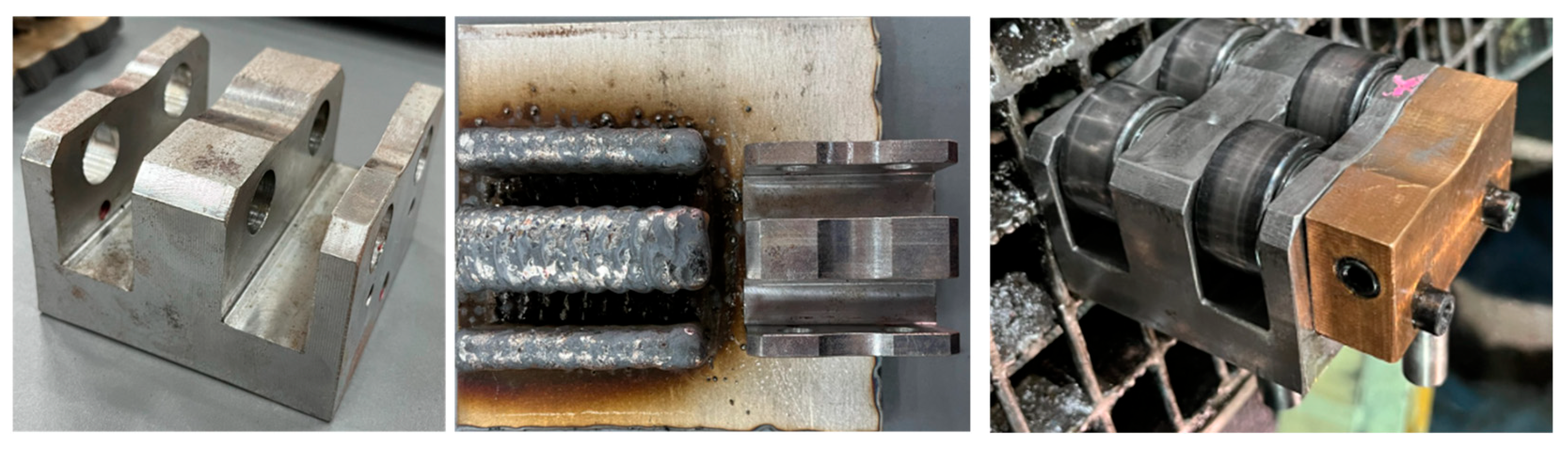
The study focuses on a component of a cold rolling mill in steelworks known as the Pollastrelli Cylinders Support Block (PCSB). This structural element is designed to securely house and align the Pollastrelli cylinders, which play a crucial role in enhancing the flatness and quality of the rolled metal. As shown in Figure 1 (left) the block features robust construction with cylindrical holes that facilitate the precise mounting and positioning of the cylinders, ensuring stability under the high mechanical stresses typical of rolling operations. Traditionally, this part is manufactured via CNC milling, a conventional subtractive process that involves removing excess material from a larger stainless steel block to achieve the desired shape. In exploring an alternative manufacturing approach, plasma-WAAM (PA-WAAM) technology was employed to produce the preform of the part, shown in Figure 1 (middle). Austenitic stainless steel AISI 316LSi wire and a plate of AISI 316L were used as filler and substrate materials, respectively. This material selection is driven by its excellent corrosion resistance, high ductility, and adaptability to various service conditions. After the PA-WAAM process, CNC milling was used to provide the final shape to the preform. To ensure visualization and understanding of the spare part, a set of photographs has been provided in Figure 1, illustrating the part after traditional manufacturing (serving as a model for comparison), the WAAM-manufactured preform, and the part in its operational context, ready for use in the rolling mill.

Figure 1.
Conventional CNC-manufactured part (left), which served as the model; plasma-WAAM preform aside the model (middle); The final part (right), produced by the WAAM-CNC hybrid manufacturing route and assembled with its additional elements, ready for use in the rolling mill.
A single component was selected as the functional unit to enable a straightforward comparison between the two manufacturing routes on a per-part basis. This approach allows for a more intuitive interpretation of environmental and economic indicators, as it links all inputs and outputs directly to the production of one finished part. The system boundary, which delineates the scope of the LCA, has been established considering the available time, financial resources, and the significance of each process stage on the overall environmental impact. While a comprehensive assessment is desirable, practical constraints require a balance between detail and efficiency. As a result, the manufacturing of machinery and tools has been excluded due to their complex subassemblies and relatively minor impact on the part’s overall life cycle. However, the transportation of raw materials and the electricity consumed by machinery during the processes are considered.
2.2. Life-Cycle Inventory
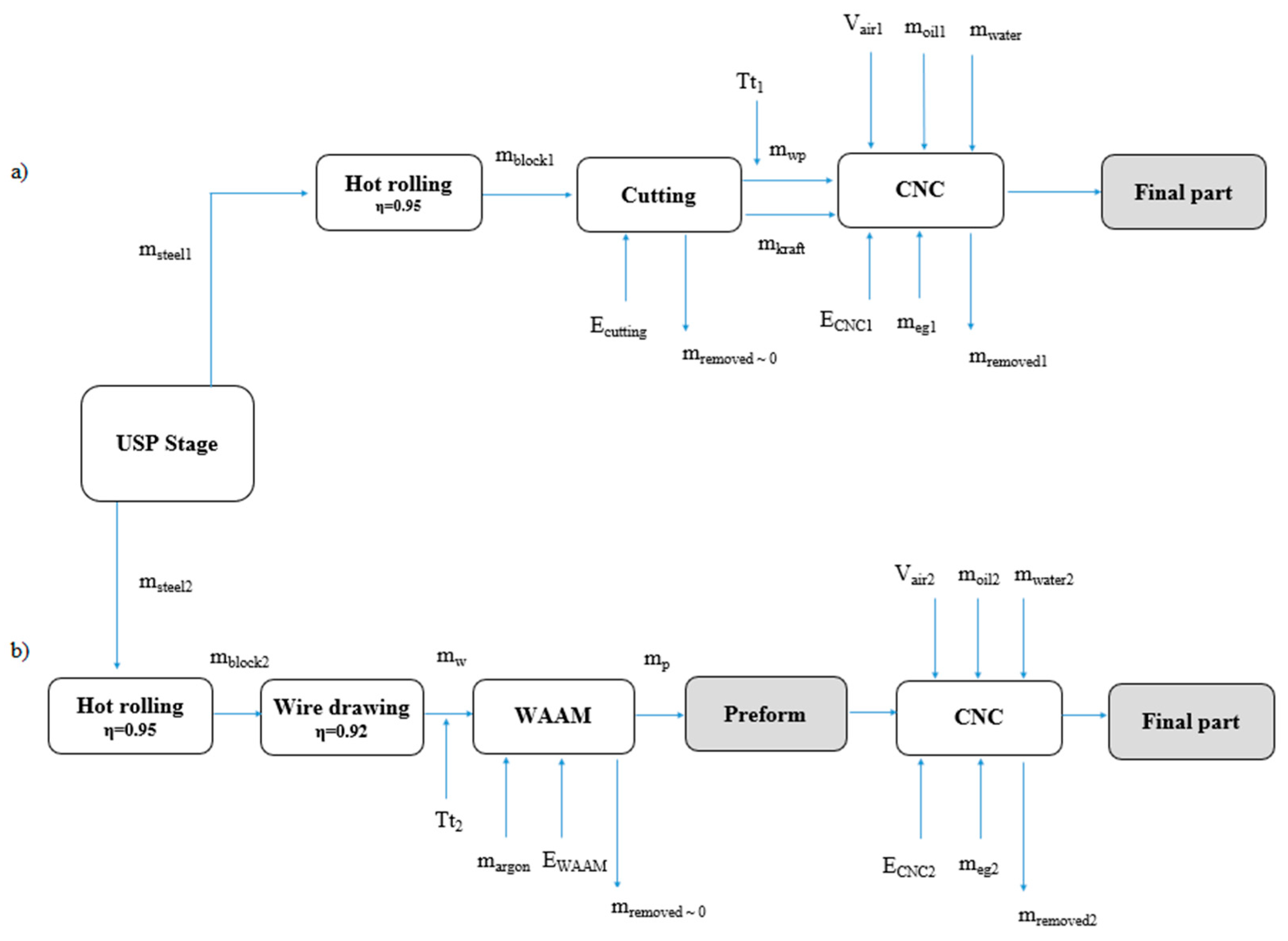
Figure 2 shows a diagram providing a visual representation of the different stages involved in the two manufacturing routes under study: the traditional based on subtractive manufacturing, in Figure 2a, and the proposed hybrid (additive–subtractive) manufacturing (WAAM-CNC), as shown in Figure 2b. The upstream steel production (USP) stage encompasses all the processes required to obtain the steel mass before it enters any specific downstream processing route. It includes raw material extraction, transportation, and primary steelmaking. The resulting steel mass (msteel1,2) serves as the input material for the subsequent differentiated processing routes analyzed in this study. Both routes produce an identical final part of PCSB and were carried out in the same workplace, the Smart Manufacturing Lab at the University of Cádiz UCA-SEA Innovation Center, located in Algeciras, Spain.
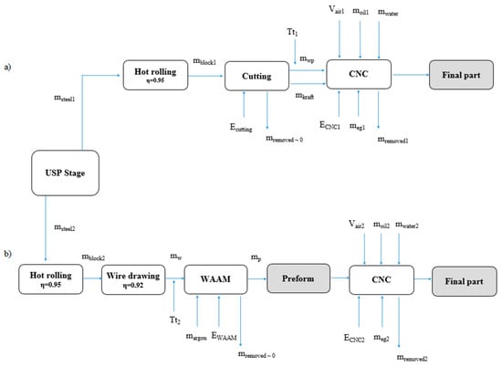
Figure 2.
Manufacturing routes with inputs and outputs for (a) the traditional manufacturing and (b) the proposed hybrid manufacturing.
2.2.1. Traditional CNC Manufacturing
A cubic block of austenitic stainless steel with 100 mm sides and a weight of 7.98 kg as workpiece material (mwp) is needed to obtain the PCSB final part by traditional CNC milling. This material was supplied wrapped in Kraft paper weighing 100 g (mKraft) by a factory 10 km away from the machining workplace. This company manufactured an original steel block, weighing mblock1, by hot rolling. According to Bekker et al. [33], the efficiency coefficient (η) for a hot rolling process is 0.95. Then, a cutting process (with an energy consumption Ecutting) was carried out to extract the cubic block from a steel billet with dimensions 200 × 200 × 5000 mm. The mass removed in this process was considered negligible compared to the mass of the entire component (mblock1 = mwp).
The equipment used to machine the final part is a LAGUN L850 (Lagun, Spain) three-axis CNC capable of machining components weighing up to 400 kg on a working surface with dimensions of 1000 × 460 mm. The equipment can accommodate up to 16 tools operating at speeds of up to 8000 rpm. The inputs for CNC milling include the steel block (mblock1), the electricity consumption (ECNC1), water (mWater1) mixed with ethylene glycol (meg1) for tool cooling, and finally, the Kraft paper used for wrapping (mKraft). Additionally, the CNC needs compressed air (Vair1) for cooling, cleaning, and controlling automated components, and lubrication (moil1) to reduce friction between moving parts and prevent wear. The compressed air was maintained at a pressure of 7 bar with a blowing flow rate of 30 L/min. The output was the material removed with the milling stage (mremoved1), and the final part.
Table 1 summarizes the terms and values introduced in the software SimaPro (PRé Sustainability B.V., Amersfoort, The Netherlands) [37] using the Ecoinvent 3 database (Ecoinvent, Zurich, Switzerland) [38]. The specified quantities define terms representing the material and energy consumed in the stages shown in Figure 2a.

Table 1.
Terms, definitions, and values used for LCA of the traditional CNC manufacturing route.
2.2.2. Hybrid WAAM-CNC Manufacturing
The preform structure shown in Figure 1 with overall dimensions of 100 × 100 × 60 mm had a mass (mp) of 2.978 kg. To manufacture it by WAAM, an austenitic stainless steel wire is needed as feeding material (mw). We consider that this process has an efficiency close to one: the same material being fed is deposited in the final printed part (mw = mp). Hence, the LCA must consider the wire drawing process to produce wires from hot-rolled bars (mblock2), a process with an efficiency coefficient of 0.92, according to Bekker et al. [33]. The material selected from the Ecoinvent 3 database was chromium steel 18/8.
The equipment used for 3D printing was a CNC machine, P1200-4X-I model, equipped with a Tetrix 552 AC/DC Synergic Plasma AW GR (SCO 4103) generator and a T drive 4 Rob 3 RE HW wire feeder. This equipment allows printing components of up to 800 × 1200 × 800 mm in dimension and 300 kg in weight. Also, this machine features a PMW 350-2 plasma torch, which allows depositing material with currents up to 350 A [39]. During the preform fabrication, the average current and voltage were set at 250 A and 22,500 mV, parameters previously adjusted by Segovia et al. [40], and the process lasted 4 h. The plasma and shielding gases used were argon at 99,999% purity (Ar5.0) and a density of 1.784 kg/m3. The inputs consisted of shielding gas (margon), electricity (EWAAM), and welding wire (mw). The shielding gas was maintained at 12 L/min. During manufacturing, the lubricating oil (moil2) consumption was considered negligible. The outputs include emissions to air, the printed object, and welding spatter (material waste). Material waste from the welding spatter was not measured directly but was considered negligible in our experience. This is supported by prior studies reporting that under optimized WAAM conditions, spatter is typically minimal [16,17]. Similarly, gaseous emissions to air (i.e., metal fumes or by-product gases) were not measured due to the lack of appropriate gas sampling equipment. This is consistent with the assumptions made in comparable WAAM-related LCA studies [22,33].
The final CNC milling of the preform to obtain the PCSB lasted 1.5 h, and inputs were electricity consumption (ECNC2) and water (mwater2) mixed with ethylene glycol in a composition of 3% (meg2) for tool and part cooling. Lubrication was carried out using oil (moil2), and compressed air (Vair2) was maintained at a pressure of 7 bar, with a flow rate of 30 L/min. Transportation (Tt2) includes the delivery to the laboratory of an 85 kg argon cylinder and a 15 kg wire spool, with suppliers located at distances of 700 km and 1117 km, respectively. Output was the removed mass (mremoved2) after the milling stage. Table 2 summarizes the terms and values introduced in SimaPro. The specified quantities define terms representing the energy consumed in each stage, as shown in Figure 2b).
Table 2.
Terms, definitions, and values used for LCA of the hybrid WAAM-CNC manufacturing route.
As a final note, in both manufacturing routes shown in Figure 2, the generated metal waste is assumed to be collected and sent for recycling, following standard residual practices. Residual fluids are managed as industrial waste as well.
2.3. Life-Cycle Impact Assessment
In this paper, we have used both Midpoint and Endpoint methodologies to evaluate the impact. Midpoint indicators, such as greenhouse gas emissions (expressed as CO2 equivalents), quantify the environmental impact of emissions and resource use at an intermediate level, reflecting changes in the natural environment [41]. While Midpoint indicators are often more straightforward to calculate and interpret, they may not fully capture the potential consequences of environmental impacts on human health and ecosystems. In this study, the environmental impact is assessed using the ReCiPe 2016 v1.1 methodology [42]. The latter was selected due to its dual approach with both midpoint and endpoint indicators, updated models, and strong compatibility with LCA tools like SimaPro. Compared to alternatives like IMPACT 2002+ or CML 2001, which offer either outdated or midpoint-only perspectives, ReCiPe allows for more complete impact interpretation. TRACI 2.1, widely used in the U.S., lacks endpoint modeling, while the newer EF 3.0 is more aligned with EU policy frameworks than scientific analysis. ReCiPe is, therefore, among the most widely used and suitable methods for comparative environmental assessments in manufacturing contexts. This method expresses results in points (Pt), where one point represents one-hundredth of the annual environmental burden of an average European citizen [43].
Endpoint indicators provide a quantitative assessment of the ultimate environmental impacts, such as human health and ecosystem damage. Impacts on human health can be expressed as Disability-Adjusted Life Years (DALYs), indicating the years of life lost or impaired due to a disease or injury [44]. Although endpoint indicators offer a more holistic perspective, they are often more complex and uncertain to quantify, requiring detailed data and sophisticated modeling techniques.
In the Recipe Endpoint methodology, the majority of the environmental impact is attributed to human health. This is due to the significant weight assigned to human health categories in the endpoint impact assessment [37]. For further information, please refer to the document by Huijbregts et al. [42].
2.4. Life-Cycle Cost
To evaluate the LCC of traditional CNC and hybrid WAAM-CNC manufacturing routes, a cradle-to-gate cost model adapted from Kokare et al. [19] was utilized. The following costs were taken into account:
- Machine Cost (). This cost factor accounts for capital expenditures on machine tools and operational costs such as maintenance and tooling. It is calculated as shown in Equation (1), where is the purchasing cost of a machine tool, is the maintenance cost of a machine tool, Ctooling is the cost of tooling such as jigs, fixtures, and cutting tools, is the total available time of a machine tool, and is the time for which a machine is used, including its setup, processing time, and clean-up:
- Material Cost (). This cost factor, computed by Equation (2), represents the consumption cost of materials for manufacturing processes. is the amount of the total material consumed, including wastes, and is the cost of 1 kg of material in EUR/kg:
- Consumables Cost (), such as electricity, shielding gas for WAAM, or cutting fluid for CNC machining. It computes as shown in Equation (3), where (kWh) is the amount of electricity consumed in a part fabrication, (EUR/kWh) is the cost of 1 kWh of electricity, (m3) is the volume of inert/shielding gas consumed in the WAAM process, and (EUR/m3) is the cost of 1 m3 of inert/shielding gas:
- Labour Cost (). It includes the expenditure related to the operator’s involvement in executing diverse tasks within each manufacturing method, including preparation, setup, processing, post-processing, and clean-up. This cost is calculated using Equation (4), where is the hourly cost of the operator, and is the total time considering all activities involving labor by the operator:
3. Results and Discussion
3.1. Life Cycle Impact Assessment and Interpretation
This section presents the resultant comparative life cycle impact assessment and interpretation from both Midpoint and Endpoint methodologies. Table 3 presents the endpoint environmental impacts associated with the traditional manufacturing route, broken down into process stages such as hot rolling, steel block production, cutting, and CNC machining. The CNC stage contributes the highest impact (3.68 Pt), primarily due to the intensive use of energy and material, while cutting has the lowest footprint. In contrast, Table 4 summarizes the endpoint impacts of the hybrid WAAM-CNC process, with wire drawing and the WAAM-CNC stage being the most significant contributors. Overall, the total environmental burden of the hybrid route (2.97 Pt) is markedly lower than that of the traditional route (7.11 Pt), demonstrating a reduction of approximately 58% in environmental impact.
Table 3.
Endpoint environmental impacts of the traditional manufacturing route. All values are expressed in points (Pt).
Table 4.
Endpoint environmental impacts of the hybrid WAAM-CNC manufacturing route. All values are expressed in points (Pt).
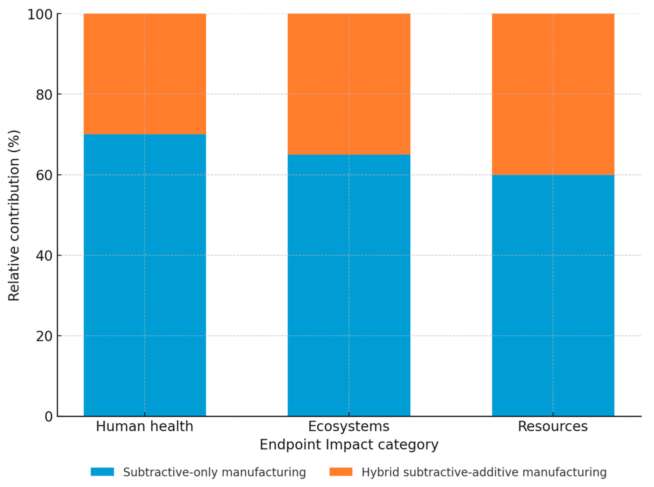
Figure 3 graphically compares the relative contribution of each manufacturing process to three endpoint categories: human health, ecosystems, and resources. The 100% stacked column chart shows that, across all categories, the hybrid subtractive–additive manufacturing process consistently exhibits a lower relative environmental impact than subtractive-only manufacturing. The most notable difference appears in the human health category, which is the most heavily weighted in the ReCiPe method. These visual results reinforce the numerical findings in Table 3 and Table 4, exhibiting the environmental benefits of transitioning to a hybrid manufacturing strategy.
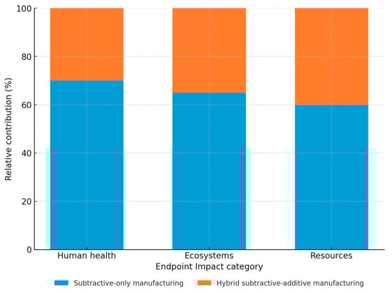
Figure 3.
Comparative analysis of endpoint environmental impact indicators for subtractive-only manufacturing (blue) versus hybrid subtractive–additive manufacturing (orange).
Table 5 details the 18 Midpoint environmental impact categories associated with the traditional manufacturing route. The units included within Table 5 and Table 6 can be interpreted as: kg PM2.5-eq (kilograms of particulate matter ≤ 2.5 µm equivalent), kg NOx (kilograms of nitrogen oxides), kg SO2-eq (kilograms of sulfur dioxide equivalent), kg P-eq (kilograms of phosphorus equivalent), kg N-eq (kilograms of nitrogen equivalent), kg 1.4-DCB (kilograms of 1,4-dichlorobenzene equivalent), m2 crop-eq (square meters of crop-equivalent land use, kg Cu-eq (kilograms of copper equivalent), kg oil-eq (kilograms of oil equivalent), and m3 (cubic meters of water consumption). The values highlighted in bold in each specific category correspond to the stage with the highest environmental impact across the entire route. The CNC milling stage exhibited a significantly higher environmental impact than the other steps involved in the production of the PCSB under study in most impact categories. The hot rolling and cutting steps showed a relatively low environmental impact.
Table 5.
ReCiPe Midpoint assessment results for the traditional manufacturing route.
Table 6.
ReCiPe Midpoint assessment results for the hybrid WAAM-CNC manufacturing route.
Table 6 details the results obtained for the 18 Midpoint environmental impact indicators associated with the WAAM-CNC hybrid manufacturing route. The values highlighted in bold correspond to the stage with the higher environmental impact of each specific category across the entire route. LCA highlights the significant environmental impact of land use associated with Kraft paper and transportation.
Among the different stages, the CNC process consistently exhibits the highest environmental loads across categories, such as global warming potential (5.58E+01 kg CO₂-eq), fine particulate matter, and ionizing radiation due to its intensive energy consumption. Hot rolling and cutting stages generally show lower impact values. Table 6 reports the corresponding midpoint impact indicators for the hybrid WAAM-CNC process. The WAAM-CNC stage stands out in categories like ionizing radiation (1.08E+00 kBq Co-60-eq) and water consumption, but the overall values remain lower than those of the traditional route in most categories. The data support that the hybrid approach significantly reduces impact in key categories such as terrestrial ecotoxicity, freshwater use, and resource scarcity.
Figure 4 shows a 100% stacked column chart to compare the Midpoint environmental impacts for the two manufacturing routes. In this graph, each column represents a specific Midpoint impact category, and the stacked segments within each column show the relative contribution of each manufacturing route. The results demonstrated that hybrid manufacturing offers a more sustainable alternative to traditional manufacturing, with a significantly lower environmental footprint.
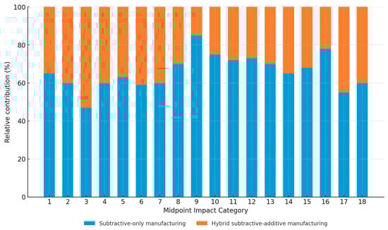
The observed reduction in environmental impacts ranges from 16.54% to 81.80%, depending on the impact category considered, thus justifying the selection of the proposed hybrid manufacturing route. Moreover, the 62.65% reduction in material quantity is consistent with the findings of other researchers [22,33]. However, in the category of ionizing radiation, WAAM-CNC exhibited a higher environmental impact. This can be attributed to the additional energy consumption required. Despite this, in regions like Spain, where electricity is primarily generated from renewable sources, this difference is minimized. According to the United Nations Scientific Committee on the Effects of Atomic Radiation, the normalized collective dose associated with the extraction and processing of minerals for solar and wind power plants is significantly lower than that of nuclear or natural gas power plants [45].
3.2. Economic Analysis (LCC)
Figure 5 shows a summary of the costs associated with the traditional manufacturing route and the hybrid route for the production of the metal PCSB under study. The analysis of cost breakdowns reveals a striking shift in expenses when transitioning from traditional manufacturing (a) to hybrid manufacturing (b). Labor costs, which represent 60% of traditional manufacturing expenses, drop to 19% in additive manufacturing. Conversely, material costs rise from 27% to 33%, and machine costs become a more significant factor, increasing from 11% to 29%.
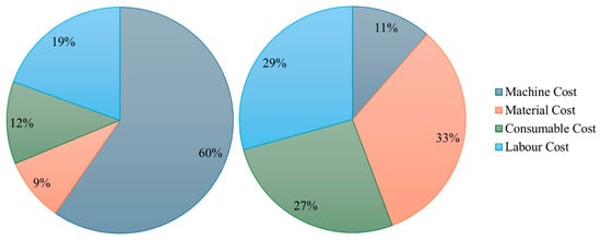
Figure 5.
Economic breakdown for (left) hybrid manufacturing and (right) subtractive-only manufacturing.
For the LCC, 250 working days with 8-h shifts were considered. The amortization period was set at 10 years for WAAM and 8 years for CNC. The manufacturing time lasted about 7 h for hybrid and 3 h for CNC. Maintenance and tooling costs were assumed to be 3% and 2% of the initial machine investment, respectively [46]. Assuming an annual gross salary of EUR 24,000 for an operator working 1600 annual hours, the labor cost amounts to EUR 15 per hour. Table 7 shows additional information used for LCC.
Table 7.
Economic Inventory data.
Taking into account the inventory collected in Table 7 and the results of the applied cradle-to-gate cost model, the total production cost of the PCSB part using the traditional route was EUR 153.63, while the hybrid process resulted in a higher cost of EUR 539.61. This increase is primarily attributed to the high initial investment in WAAM equipment and the elevated material cost. The detailed cost breakdown highlights a considerable reduction in labor costs, which drop from 60% in traditional CNC to 19% in the hybrid process due to reduced manual intervention. On the other hand, machine and material costs become more dominant in the hybrid approach, rising to 29% and 33%, respectively, compared to 11% and 27% in the conventional method. Despite its current cost disadvantage, the hybrid WAAM/CNC process is expected to become more cost-competitive over time as the additive manufacturing sector matures and economies of scale improve.
4. Conclusions
This study conducted a comparative environmental and economic assessment of two alternative manufacturing routes for a steel mill spare part (Pollastrelli cylinders support block): a conventional subtractive-only method based on CNC machining and a proposed hybrid approach combining plasma-based Wire Arc Additive Manufacturing (WAAM) with CNC finishing. Through a detailed Life Cycle Assessment (LCA) and Life Cycle Costing (LCC), the research aimed to evaluate the sustainability and feasibility of adopting the hybrid route in an industrial context. The main conclusions are:
- The LCA revealed that the hybrid WAAM-CNC route offers considerable environmental benefits across both the Midpoint and Endpoint impact categories.
- Specifically, the hybrid approach led to an average reduction of 49% in environmental impact categories, with individual reductions ranging from 16.54% to 81.80%, depending on the category.
- Endpoint results indicated that the most significant improvements were associated with human health impact, which is the most heavily weighted category in the ReCiPe methodology.
- The WAAM-based route also achieved approximately 70% material savings and an 80% reduction in steel waste, largely due to the near-net-shape capability of additive manufacturing.
- The only notable exception was the ionizing radiation category, where the hybrid process exhibited a higher impact due to increased electricity consumption. This impact could be mitigated in regions with electricity sourced from renewables, such as Spain.
- Transport impacts were found to be significant across multiple categories, suggesting that sourcing materials from local suppliers could help further reduce environmental burdens.
- The use of Kraft paper, which notably affects land use, could be optimized by reusing it in future operations to minimize waste.
- From an economic standpoint, the Life Cycle Cost (LCC) analysis showed that the hybrid manufacturing route incurred a unit production cost approximately 3.5 times higher than the conventional one (EUR 539.61 vs. EUR 153.63). This cost difference is primarily driven by the high initial investment in WAAM equipment and the associated material costs.
- The hybrid process substantially reduced operational costs, including:
- ▪
- A 66% decrease in labor expenses;
- ▪
- A 45% reduction in consumables;
- ▪
- A 28% drop in material costs.
- The shift in the cost structure reflects a move toward capital-intensive, automated manufacturing systems, where machine and material costs become more dominant and ongoing operational costs are reduced.
Overall, the results support the viability of the WAAM-CNC hybrid route as a more environmentally sustainable manufacturing solution, with interesting economic potential in the long term as equipment costs decrease and the AM sector continues to mature. Beyond these environmental and economic benefits, the hybrid process aligns with Industry 5.0 goals by promoting material efficiency and supporting circularity. Its integration of additive and subtractive technologies also enables more human-centered automation, enhancing rather than replacing skilled labour. These features contribute to a more resilient and forward-looking manufacturing model.
As a final note, one limitation of using LCA as the sole metric for evaluating environmental impacts is that it quantifies material and energy consumption during the manufacturing process without considering the mechanical properties of the produced parts.
Future developments could explore the integration of more energy-efficient WAAM systems, the use of renewable energy sources to reduce electricity-related impacts (e.g., ionizing radiation), and the application of the hybrid process to other part geometries and materials. Expanding the analysis to include multi-part production scenarios and dynamic cost modeling could offer a more comprehensive understanding of its industrial potential.
Author Contributions
Conceptualization, L.S.-G., N.B., J.J.G.-G., and D.L.S.; methodology, L.S.-G., N.B., J.J.G.-G., A.J.G.-M., and D.L.S.; software J.J.G.-G. and A.J.G.-M.; validation, L.S.-G. and J.J.G.-G.; formal analysis, L.S.-G. and J.J.G.-G.; investigation J.J.G.-G.; resources D.L.S.; data curation J.J.G.-G. and A.J.G.-M.; writing—original draft preparation, J.J.G.-G., N.B., and L.S.-G.; writing—review and editing, N.B., D.L.S., and A.J.G.-M.; visualization. L.S.-G., N.B., A.J.G.-M., and D.L.S.; supervision, N.B., D.L.S., and A.J.G.-M.; project administration, D.L.S.; funding acquisition, D.L.S. All authors have read and agreed to the published version of the manuscript.
Funding
This research was funded by the Spanish Ministerio de Ciencia e Innovación (project reference EQC2019-006374-P), Junta de Andalucía (research group INNANOMAT ref. TEP-946), the University of Cadiz’s Support and Stimulus Plan for Research and Transfer 2022–2023, and the II Call for research project grants of the Cepsa Foundation Chair 2023, project: Industrial Maintenance with Additive Manufacturing: A Sustainable Paradigm for the Circular Economy and Energy Transition. Reference: CCep2023-3. Co-funding from UE is also acknowledged. L. Segovia-Guerrero acknowledges the grant ‘Proyecto Singular UCA-SEA-3’ from UCA.
Data Availability Statement
Data are available upon request.
Acknowledgments
The authors acknowledge Juan Almagro and José Santamaría of Acerinox group for providing practical information on the real case studied in this article and the Acerinox Chair of the University of Cadiz for the institutional support provided.
Conflicts of Interest
The authors declare no conflicts of interest.
Abbreviations
The following abbreviations are used in this manuscript:
| AC/DC | Alternating current/direct current |
| AW | Arc welding |
| LCA | Life cycle assessment |
| LCC | Life cycle costing |
| CNC | Computer numerical control |
| PA-WAAM | Plasma arc-wire arc additive manufacturing |
| AM | Additive manufacturing |
| SM | Subtractive manufacturing |
| GTA | Gas tungsten arc |
| PCSB | Pollastrelli cylinders support block |
| Pt | Points |
| USP | Upstream steel production |
References
- Organisation for Economic Co-Operation and Development (OECD). Material Resources, Productivity and the Environment Key Findings; Organisation for Economic Co-Operation and Development (OECD): Paris, France, 2007. [Google Scholar]
- Jayawardane, H.; Davies, I.J.; Gamage, J.R.; John, M.; Biswas, W.K. Sustainability perspectives—A review of additive and subtractive manufacturing. Sustain. Manuf. Serv. Econ. 2023, 2, 100015. [Google Scholar] [CrossRef]
- Muslemani, H.; Liang, X.; Kaesehage, K.; Ascui, F.; Wilson, J. Opportunities and challenges for decarbonizing steel production by creating markets for ‘green steel’ products. J. Clean. Prod. 2021, 315, 128127. [Google Scholar] [CrossRef]
- Vögele, S.; Grajewski, M.; Govorukha, K.; Rübbelke, D. Challenges for the European steel industry: Analysis, possible consequences and impacts on sustainable development. Appl. Energy 2020, 264, 114633. [Google Scholar] [CrossRef]
- Böckin, D.; Tillman, A.M. Environmental assessment of additive manufacturing in the automotive industry. J. Clean. Prod. 2019, 226, 977–987. [Google Scholar] [CrossRef]
- Ingarao, G.; Priarone, P.C.; Deng, Y.; Paraskevas, D. Environmental modelling of aluminium based components manufacturing routes: Additive manufacturing versus machining versus forming. J. Clean. Prod. 2018, 176, 261–275. [Google Scholar] [CrossRef]
- Watson, J.K.; Taminger, K.M.B. A decision-support model for selecting additive manufacturing versus subtractive manufacturing based on energy consumption. J. Clean. Prod. 2018, 176, 1316–1322. [Google Scholar] [CrossRef]
- Rahman, M.A.; Saleh, T.; Jahan, M.P.; McGarry, C.; Chaudhari, A.; Huang, R.; Tauhiduzzaman, M.; Ahmed, A.; Al Mahmud, A.; Bhuiyan, S.; et al. Review of Intelligence for Additive and Subtractive Manufacturing: Current Status and Future Prospects. Micromachines 2023, 14, 508. [Google Scholar] [CrossRef] [PubMed]
- Adam, A.; Sam, T.H.; Latif, K.; Yusof, Y.; Khan, Z.; Ali Memon, D.; Saif, Y.; Hatem, N.; lliyas Ahmed, M.; Abdul Kadir, A.Z. Review on Advanced CNC Controller for Manufacturing in Industry 4.0. Lect. Notes Mech. Eng. 2022, 261–269. [Google Scholar] [CrossRef]
- Soori, M.; Arezoo, B.; Dastres, R. Robotical Automation in CNC Machine Tools, A Review. Acta Mech. Autom. 2023, 18, 434–450. [Google Scholar] [CrossRef]
- Wankhede, V.A.; Vinodh, S. Analysis of challenges of wire-arc additive manufacturing process in the context of Industry 4.0 using graph theory approach. Int. J. Adv. Manuf. Technol. 2022, 123, 1059–1078. [Google Scholar] [CrossRef]
- Li, J.L.Z.; Alkahari, M.R.; Rosli, N.A.B.; Hasan, R.; Sudin, M.N.; Ramli, F.R. Review of wire arc additive manufacturing for 3d metal printing. Int. J. Autom. Technol. 2019, 13, 346–353. [Google Scholar] [CrossRef]
- Korgancı, M.; Bozkurt, Y. Recent developments in additive friction stir deposition (AFSD). J. Mater. Res. Technol. 2024, 30, 4572–4583. [Google Scholar] [CrossRef]
- Zhang, C.; Yu, H.; Sun, D.; Liu, W. Ultrasonic Additive Manufacturing of Metallic Materials. Metals 2022, 12, 1912. [Google Scholar] [CrossRef]
- Vaz, R.F.; Garfias, A.; Albaladejo, V.; Sanchez, J.; Cano, I.G. A Review of Advances in Cold Spray Additive Manufacturing. Coatings 2023, 13, 267. [Google Scholar] [CrossRef]
- Shah, A.; Aliyev, R.; Zeidler, H.; Krinke, S. A Review of the Recent Developments and Challenges in Wire Arc Additive Manufacturing (WAAM) Process. J. Manuf. Mater. Process. 2023, 7, 97. [Google Scholar] [CrossRef]
- Alaboudi, S.F.; Khan, M.A.A.; Asad, M.; Khan, M.; Djavanroodi, F. The Innovation in wire arc additive manufacturing (WAAM): A review. Mater. Res. Proc. 2023, 31, 522–530. [Google Scholar] [CrossRef]
- Zahidin, M.R.; Yusof, F.; Rashid, S.H.A.; Mansor, S.; Raja, S.; Jamaludin, M.F.; Manurung, Y.H.; Adenan, M.S.; Hussein, N.I.S. Research challenges, quality control and monitoring strategy for Wire Arc Additive Manufacturing. J. Mater. Res. Technol. 2023, 24, 2769–2794. [Google Scholar] [CrossRef]
- Kokare, S.; Oliveira, J.P.; Godina, R. A LCA and LCC analysis of pure subtractive manufacturing, wire arc additive manufacturing, and selective laser melting approaches. J. Manuf. Process. 2023, 101, 67–85. [Google Scholar] [CrossRef]
- Ingarao, G.; Priarone, P.C. A comparative assessment of energy demand and life cycle costs for additive- and subtractive-based manufacturing approaches. J. Manuf. Process. 2020, 56, 1219–1229. [Google Scholar] [CrossRef]
- Chaurasia, M.; Sinha, M.K. Investigations on Process Parameters of Wire Arc Additive Manufacturing (WAAM): A Review. Lect. Notes Mech. Eng. 2021, 845–853. [Google Scholar] [CrossRef]
- Reis, R.C.; Kokare, S.; Oliveira, J.P.; Matias, J.C.O.; Godina, R. Life cycle assessment of metal products: A comparison between wire arc additive manufacturing and CNC milling. Adv. Ind. Manuf. Eng. 2023, 6, 100117. [Google Scholar] [CrossRef]
- Duan, X.; Cui, R.; Yang, H.; Yang, X. Hybrid Additive and Subtractive Manufacturing Method Using Pulsed Arc Plasma. Materials 2023, 16, 4561. [Google Scholar] [CrossRef]
- Pant, H.; Arora, A.; Gopakumar, G.S.; Chadha, U.; Saeidi, A.; Patterson, A.E. Applications of wire arc additive manufacturing (WAAM) for aerospace component manufacturing. Int. J. Adv. Manuf. Technol. 2023, 127, 4995–5011. [Google Scholar] [CrossRef]
- Chauhan, S.; Narasimhulu, A. Comprehensive Study on Wire Arc Additive Manufacturing (WAAM). In Lecture Notes in Mechanical Engineering; Springer Science and Business Media Deutschland GmbH: Singapore, 2024; pp. 281–305. [Google Scholar] [CrossRef]
- Diemer, A. From Life Cycle Assessment (LCA) to Life Cycle Sustainability Assessment (LCSA), methodological issues and prospects for implementing circular business models. Int. J. Sci. Eng. Appl. Sci. (IJSEAS) 2023. Available online: https://ijseas.com/volume9/v9i12/IJSEAS202312101.pdf (accessed on 1 March 2025).
- Brusseau, M.L. Sustainable Development and Other Solutions to Pollution and Global Change, 3rd ed.; Elsevier Inc.: Amsterdam, The Netherlands, 2019. [Google Scholar] [CrossRef]
- Mecheter, A.; Tarlochan, F.; Kucukvar, M. A Review of Conventional versus Additive Manufacturing for Metals: Life-Cycle Environmental and Economic Analysis. Sustainability 2023, 15, 12299. [Google Scholar] [CrossRef]
- Ramesh, P.; Vinodh, S. State of art review on Life Cycle Assessment of polymers. Int. J. Sustain. Eng. 2020, 13, 411–422. [Google Scholar] [CrossRef]
- Ramachandran, K.; Gnanasagaran, C.L.; Vekariya, A. Life cycle assessment of carbon fiber and bio-fiber composites prepared via vacuum bagging technique. J. Manuf. Process. 2023, 89, 124–131. [Google Scholar] [CrossRef]
- Baiocco, G.; Salvi, D.; Ucciardello, N. Sustainable coating solutions: A comparative life cycle analysis of electrophoretic deposition and electroplating for graphene-reinforced anti-wear coatings. Int. J. Adv. Manuf. Technol. 2024, 130, 3341–3354. [Google Scholar] [CrossRef]
- Amahmoud, A.; El Attar, M.M.; Meleishy, A. The Evolution of Life Cycle Assessment Approach: A Review of Past and Future Prospects. IOP Conf. Ser. Earth Environ. Sci. 2022, 992, 012002. [Google Scholar] [CrossRef]
- Bekker, A.C.M.; Verlinden, J.C. Life cycle assessment of wire + arc additive manufacturing compared to green sand casting and CNC milling in stainless steel. J. Clean. Prod. 2018, 177, 438–447. [Google Scholar] [CrossRef]
- Campatelli, G.; Montevecchi, F.; Venturini, G.; Ingarao, G.; Priarone, P.C. Integrated WAAM-Subtractive Versus Pure Subtractive Manufacturing Approaches: An Energy Efficiency Comparison. Int. J. Precis. Eng. Manuf.-Green Technol. 2020, 7, 1–11. [Google Scholar] [CrossRef]
- Mattos, B.M.; Da Cruz, J.; Filho, P.; De Souza Guimarães, C. Life Cycle Assessment in Flange Part Production Comparing Wire and Arc Additive Manufacturing Method (WAAM) and Conventional Manufacturing in Terms of Energy Consumption, Greenhouse Gas Emissions and Solid Waste Generation. Preprints 2023. [Google Scholar] [CrossRef]
- ISO 14044:2006; Environmental Management. Life Cycle Assessment. Requirements and Guidelines. International Organization for Standarization: Geneva, Switzerland, 2006. Available online: https://www.iso.org/standard/38498.html (accessed on 24 March 2025).
- Sustainability B, SimaPro Database Manual-Methods Library. Available online: https://simapro.com/wp-content/uploads/2022/07/DatabaseManualMethods.pdf (accessed on 5 March 2025).
- Wernet, G.; Bauer, C.; Steubing, B.; Reinhard, J.; Moreno-Ruiz, E.; Weidema, B. The ecoinvent database version 3 (part I): Overview and methodology. Int. J. Life Cycle Assess. 2016, 21, 1218–1230. [Google Scholar] [CrossRef]
- Segovia-Guerrero, L.; Baladés, N.; Attard, B.; De Nicolás, M.; Scotti, A.; Zammit, A.; Sales, D.L. Multi-material stainless steel fabrication using plasma wire arc additive manufacturing. J. Mater. Res. Technol. 2024, 30, 3996–4002. [Google Scholar] [CrossRef]
- Segovia-Guerrero, L.; Gil-Mena, A.J.; Baladés, N.; Sales, D.L.; Fonollá, C.; de la Mata, M.; de Nicolás-Morillas, M. Influence of Printing Parameters on the Morphological Characteristics of Plasma Directed Energy-Deposited Stainless Steel. J. Manuf. Mater. Process. 2024, 8, 233. [Google Scholar] [CrossRef]
- Dekker, E.; Zijp, M.C.; van de Kamp, M.E.; Temme, E.H.M.; van Zelm, R. A taste of the new ReCiPe for life cycle assessment: Consequences of the updated impact assessment method on food product LCAs. Int. J. Life Cycle Assess. 2020, 25, 2315–2324. [Google Scholar] [CrossRef]
- Huijbregts, M.A.J.; Steinmann, Z.J.N.; Elshout, P.M.F.; Stam, G.; Verones, F.; Vieira, M.; Zijp, M.; Hollander, A.; van Zelm, R. ReCiPe2016: A harmonised life cycle impact assessment method at midpoint and endpoint level. Int. J. Life Cycle Assess. 2017, 22, 138–147. [Google Scholar] [CrossRef]
- Huysman, S.; Schaubroeck, T.; Goralczyk, M.; Schmidt, J.; Dewulf, J. Quantifying the environmental impacts of a European citizen through a macro-economic approach, a focus on climate change and resource consumption. J. Clean. Prod. 2016, 124, 217–225. [Google Scholar] [CrossRef]
- Ibrahim, R.A.; Inan, H.; Fahim, I.S. A comparative cradle-to-gate life cycle assessment of three cotton stalk waste sustainable applications. Sci. Rep. 2023, 13, 20781. [Google Scholar] [CrossRef]
- United Nations Scientific Committee on the Effects of Atomic Radiation. UNSCEAR 2012 Report to the General Assembly with Scientific Annexes. New York. 2015. Available online: https://www.unscear.org/unscear/en/publications/2012.html (accessed on 17 March 2025).
- Pusavec, F.; Kramar, D.; Krajnik, P.; Kopac, J. Transitioning to sustainable production—Part II: Evaluation of sustainable machining technologies. J. Clean. Prod. 2010, 18, 1211–1221. [Google Scholar] [CrossRef]
- Statista. Electricidad: Precio Medio Final España 2010–2025. Available online: https://es.statista.com/estadisticas/993787/precio-medio-final-de-la-electricidad-en-espana/ (accessed on 12 April 2025).


Disclaimer/Publisher’s Note: The statements, opinions and data contained in all publications are solely those of the individual author(s) and contributor(s) and not of MDPI and/or the editor(s). MDPI and/or the editor(s) disclaim responsibility for any injury to people or property resulting from any ideas, methods, instructions or products referred to in the content. |
© 2025 by the authors. Licensee MDPI, Basel, Switzerland. This article is an open access article distributed under the terms and conditions of the Creative Commons Attribution (CC BY) license (https://creativecommons.org/licenses/by/4.0/).