Article

Design and Manufacture of a Flexible Adaptive Fixture for Precision Grinding of Thin-Walled Bearing Rings

1
School of Mechanical Engineering, Xi’an Jiaotong University, Xi’an 710049, China
2
National Key Laboratory of High-Performance Tools, Zhengzhou Abrasives & Abrasive Tools & Grinding Research Institute Co., Ltd., Zhengzhou 450000, China
3
Aerospace and Astronautics Propulsion (Taihu) Research Institute, Wuxi 214000, China
4
Department of Computer Science, KU Leuven, 3001 Leuven, Belgium
5
Department of Mechanical Engineering, KU Leuven, 3001 Leuven, Belgium
*
Authors to whom correspondence should be addressed.
J. Manuf. Mater. Process. 2025, 9(5), 139; https://doi.org/10.3390/jmmp9050139
Submission received: 30 March 2025 / Revised: 17 April 2025 / Accepted: 17 April 2025 / Published: 22 April 2025

Abstract

:
Addressing the issues of easy deformation and difficult-to-control machining accuracy of thin-walled bearing rings during precision grinding due to clamping forces, existing research mainly employs methods such as elastic clamping, hydraulic control, pneumatic control, and vacuum adsorption to tackle the clamping problem. However, these methods still suffer from problems such as uneven clamping force, insufficient adaptability, and limited machining accuracy. In this paper, a novel fixture suitable for precision grinding of thin-walled bearing rings is designed. By analyzing the working principle of the fixture and considering the processing characteristics of thin-walled bearing rings, the fixture structure is designed and optimized to enhance its clamping stability and machining accuracy. Modal analysis and stress-displacement analysis are conducted to verify the stability and performance of the new fixture during the machining process. The research results show that the fixture can effectively reduce the deformation of thin-walled bearing rings, improve machining quality and efficiency, and provide a feasible solution for high-precision grinding of thin-walled bearing rings.

1. Introduction

As a core component of high-precision bearings, thin-walled bearing rings are widely used in aerospace, precision machinery, automotive industry, medical equipment, and other fields, and their machining accuracy directly affects the performance and service life of bearings. However, thin-walled bearing rings are characterized by thin wall thickness and poor rigidity and are very susceptible to elastic deformation during the grinding process, which leads to difficulty in controlling the dimensional accuracy and form and position tolerances and becomes a bottleneck, restricting the high-precision manufacturing of the rings [1]. In particular, when large amounts of material are removed (up to 80% to 90%), the original stress equilibrium inside the workpiece is broken. The redistribution of residual stresses can lead to severe deformations when the fixture is released [2]. Therefore, the clamping method is one of the key factors affecting the machining accuracy of thin-walled workpieces [3].
The main challenges faced during the machining of thin-walled bearing rings are deformation, vibration, and surface quality problems due to low stiffness [4]. Part deformation is closely related to residual stresses (internal forces) and clamping boundary conditions (external forces). As a key component to avoid deformation caused by external loads during machining, the design of the fixture has an important impact on machining accuracy [5]. Traditional fixtures in thin-walled parts machining have problems such as uneven clamping force distribution and an inability to adapt to the deformation of the workpiece, which leads to low machining accuracy and efficiency [6]. Patalas et al. [7] focused on the deformation of thin-walled bearing rings in the process of turning machining due to the clamping force of hydraulic chucks and showed that at the lowest clamping force (10 KN), the three-jaw chuck will cause the deformation of the bearing ring to be 0.09 mm, while a six-jaw chuck can reduce the maximum deformation to 5 μm to meet the geometric tolerances, which indicates that the selection of suitable fixtures is crucial in high-precision machining situations.
In order to overcome the limitations of traditional fixtures, adaptive fixtures technology is gradually emerging. Adaptive fixtures, through the integration of sensors, actuators, and intelligent control systems, can monitor machining status in real time and dynamically adjust the clamping force and support position, thus significantly improving machining quality and efficiency. Chen et al. [8] have proposed a prediction model based on the DBO-1DCNN-LSTM algorithm for real-time prediction of surface roughness during the grinding process. This study achieved high accuracy surface roughness prediction by combining vibration signals, acoustic emission signals, and machining parameters. This result shows that adaptive technology and multi-source signal fusion can significantly improve the machining accuracy and stability in the machining of thin-walled bearing rings. In the research area of adaptive fixturing technology, Chai et al. [9] have proposed an adaptive fixture for machining thin-walled aerospace engine magazines with integrated vibration suppression and workpiece deformation measurement. The fixture provides adaptive support force through cylinder-driven support blocks to increase local stiffness and damping while using displacement sensors to measure workpiece deformation during and after machining. Gonzalo et al. [5] proposed a smart fixture design method for reducing workpiece deformation. The new smart fixture controls the deformation of the workpiece by measuring the reaction force at the clamping point and by combining the locator and clamping function, which is capable of holding the workpiece without introducing additional deformation and actively adjusting the clamping position to compensate for the deformation. Li et al. [10] proposed a novel low-stress machining fixturing method using a flexible fixture design capable of responding to workpiece deformation in real time during machining. The workpiece is supported and fixed by a set of adjustable flexible fixtures, and the fixture layout is determined according to the workpiece rigidity analysis. During machining, the deformation of the workpiece is monitored online by digitized probes or sensors, and the fixture can adjust the position and orientation of the workpiece in real time according to the monitoring data.
Hao et al. [11] have proposed an improved adaptive auxiliary fixture, which avoids the use of low melting point alloys by redesigning the fixture structure while realizing adaptive clamping of thin-walled parts. The improved fixture can realize adaptive clamping of workpieces by simple tightening and loosening operations, which significantly improves the machining efficiency and safety. Zhou et al. [12] proposed an adaptive clamping system based on phase change materials for controlling the machining deformation of aerospace thin-walled parts. The system is capable of adjusting the clamping position to adapt to the deformation of the workpiece during machining. The phase change material can adjust the clamping position when it is in the liquid state to follow the deformation of stress release after rough machining; the material can be reclamped after curing, when the internal stresses in the workpiece have been minimized. Gandhi et al. [13] (1986) proposed an adaptive fixture design based on the fluidized bed technology in their study, which takes advantage of the characteristics of the fluidized bed to automatically adjust the clamping force and support force according to the shape of the workpiece and the machining. This fixture design utilizes the characteristics of the fluidized bed to automatically adjust the clamping force and support position according to the shape of the workpiece and the machining demand, thus significantly reducing the deformation caused by the clamping force and residual stress during the machining process. Wang et al. [14] designed a fixture using a low-melting-point alloy, which is heated so that the alloy melts and fills up the gap between the part and fixture and then cools down to form a rigid body to achieve the positioning and clamping of the part. The machining method of the fixture using a low-melting-point alloy has a material removal rate of only half of the conventional method (37.5% vs. 71.5%), which significantly improves the economy.
Jiang et al. [15] proposed a flexible fixture method based on magnetorheological fluid (MRF). Compared with traditional fixtures, the machining method using MRF flexible fixtures significantly reduces cutting forces, residual stresses, and surface roughness, thereby improving machining quality and surface finish. However, the study still falls short in practical application validation, especially in terms of the uniformity of magnetic field strength and the reusability of MRF materials. Merlo et al. [16] introduced a novel adaptive fixture system, specifically designed for the machining of thin-walled aerospace components. The system, based on active clamping force from piezoelectric actuators, can automatically adapt to changes in the shape and size of the workpiece, significantly reducing setup time and recovering deformations introduced by the clamping process through closed-loop control. However, the hysteresis characteristics of piezoelectric actuators may affect control accuracy, necessitating further research to enhance the system’s dynamic performance. Papastathis et al. [17] coupled the finite element model of the workpiece with the analytical model of the fixture through impedance coupling technology, establishing a complete fixture-workpiece system model. This model can reflect the characteristics of the workpiece, the boundary conditions, the external loads, and the dynamic response of fixture components. Bakker et al. [18] developed an active control fixture system capable of real-time adjustment of clamping force. The PI controller, by adjusting the clamping force in real time, significantly reduces the reaction forces on the fixture supports due to machining loads, thereby improving machining accuracy.
In recent years, with the continuous development of simulation technology, it has been widely used in the study of fixture systems, which provides a powerful support for the design, performance evaluation, and optimization of fixtures. Kashyap et al. [19] proposed a fixture design method combining finite element analysis and optimization algorithms, which is able to effectively reduce the deformation of the workpiece during machining and improve the machining accuracy and quality. Ivanov et al. [20] conducted a finite element analysis of the new fixture by ANSYS Workbench to investigate the deformation and stress of the fixture under different materials (e.g., steel, cast iron, and aluminum alloy) and machining steps. The results show that the maximum displacement and equivalent stresses of the new fixture during machining are significantly lower than those of the traditional fixture, which improves the machining accuracy. Calabrese et al. [21] proposed a new method of fixture design based on topology optimization. By optimizing the material distribution, the fixture is able to meet the demand of machining stiffness and, at the same time, significantly reduce its own weight, which demonstrates the potential of topology optimization technology in the design of complex structures. Andrews et al. [22] proposed an integrated approach based on a rigid body model (and genetic algorithm) for optimizing fixture layout and clamping force. The study predicted the contact force between the fixture and the workpiece through simulation analysis and used it as an optimization objective to minimize the elastic deformation of the workpiece during machining. Chen [23] et al. developed a numerical simulation model that equates dynamic loads to static loads, which was able to simulate the dynamic response of the safety pins under emergency separation conditions. With this model, the researchers were able to analyze the dynamic response and load of the safety pin at different points in time and discretize it into an equivalent static load. Hamedi et al. [24] proposed a workholding simulation method based on the finite element method for evaluating the output of automated fixture design systems. The method simulates the frictional interaction between the workpiece and the fixture through nonlinear finite element analysis, which takes into account the effect of friction on clamping and workpiece rigid body stability.
Kaya [25] proposed a fixture layout optimization method based on the combination of genetic algorithm and finite element analysis, verified the effectiveness of GA in multimodal optimization problems, and also demonstrated the significant advantages of the method in reducing the elastic deformation of workpieces through actual machining cases. Yang et al. [26] focused on the multi-objective optimization of the positioning layout of fixtures for thin plate parts. The study used the “N-2-1” positioning principle to generate training and test sample sets through finite element analysis and Latin hypercube sampling and developed a kriging-based agent model for predicting the nonlinear relationship between the fixture layout and the overall and maximum deformation of thin plate parts. Sikström et al. [27] have described in detail how computer-aided robotics (CAR) simulation can be combined with finite element modeling for optimization of welding sequences and fixture design. Yu et al. [28] described in detail how to optimize fixture layouts through a combination of finite element analysis and response surface methodology. In the study, the thermal history and residual stress distribution during the welding process were first simulated by FEA, and then the relationship between welding deformation and fixture parameters was modeled by the response surface method. Siebenaler et al. [29] used finite element analysis (FEA) to model the fixture-workpiece system and to explore the effect of the compliance of the fixture body on the deformation of the workpiece.
Aiming at the problems of insufficient dynamic control accuracy, material and structural limitations, and high complexity of system integration in the current fixtures, this paper proposes a new adaptive grinding fixture design scheme by analyzing the clamping principle of adaptive fixture and combining it with the grinding processing characteristics of thin-walled bearing rings and conducts finite element analysis on the scheme to verify the reliability of the fixture. By optimizing the structure design and control strategy, the fixture can better adapt to the processing needs of thin-walled bearing rings and effectively reduce the deformation in the grinding process. It also provides higher system rigidity as well as dynamic stability for the bearing ring grinding process and improves the machining accuracy of the workpiece.

2. Adaptive Flexible Fixture Design

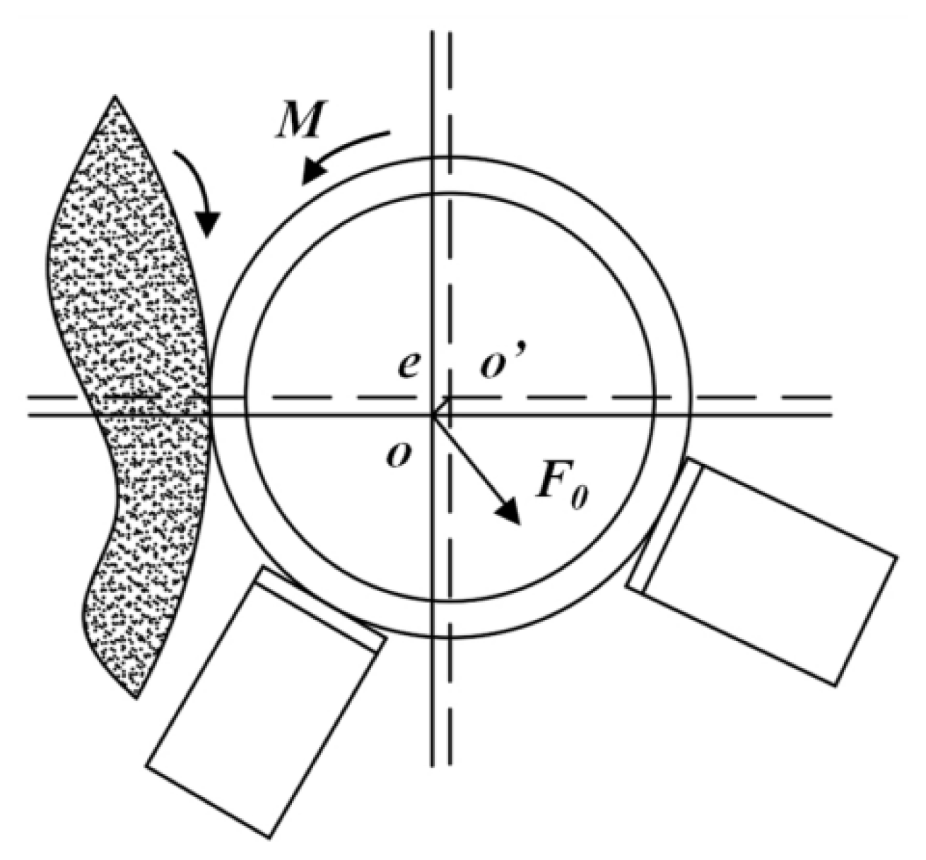
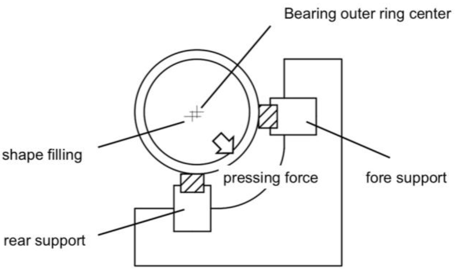
2.1. Grinding Fixture Principle and Defect Analysis

Centerless grinding can eliminate the eccentricity error caused by the eccentricity of the fixture or the instability of the workpiece during the grinding process, with high positioning accuracy and easy loading and unloading, which can realize automated production and high production efficiency [30]. Therefore, in the bearing ring grinding process, centerless grinding fixtures have become a standardized clamping method, which can be divided into roller type, mechanical compression wheel type, and electromagnetic type according to its mode of operation, in which the electromagnetic type has the characteristics of small deformation of the workpiece, machining accuracy higher than the spindle rotary accuracy, good machining surface quality, etc., and it is widely used in the precision machining of the bearing ring, especially in the machining of the thin-walled bearing ring.
The electromagnetic centerless grinding fixture utilizes the principles of electromagnetism to generate a magnetic field, which magnetizes the bearing ring. This enables the end face of the bearing ring to be adsorbed and fixed, thereby achieving axial positioning and clamping of the bearing ring. The radial positioning of the bearing ring is realized by two supports. Depending on the relative positions of the supports, the workpiece, and the grinding wheel, the configurations are classified as external support for external grinding (support outer to grind outer), external support for internal grinding (support outer to grind inner), and internal support for external grinding (support inner to grind outer).
The approach adopted in this study is external support for external grinding, and the mechanical principle diagram is shown in Figure 1. During the grinding process, the workpiece generally exhibits varying degrees of run-out due to its original geometric accuracy and other factors. Therefore, to ensure the smooth progress of the grinding process, an eccentricity (denoted as e in the figure) must be set between the center of the bearing ring and the center of the magnetic pole during the initial installation. This ensures that as the magnetic pole rotates around the workpiece axis, the bearing ring will rotate around the geometric center formed by the contact points of the two supports and the grinding wheel. As a result, sliding friction occurs between the end face of the bearing ring and the end face of the magnetic pole. Under the adsorption of the magnetic force, a sliding friction force is generated between them, which can be equivalently represented as a frictional resultant force perpendicular to the eccentric direction and pointing towards the two support blocks and a resultant torque. The former is the radial clamping force, acting at the center of the ring. The radial positioning and clamping of the bearing ring are achieved under the combined action of the magnetic pole, the fixture body, and the support blocks. The frictional force and torque ensure that the bearing ring remains in tight contact with the two support blocks, enabling the bearing ring to achieve stable rotational motion during the grinding process.
The structure of the traditional electromagnetic centerless grinding fixture is shown in Figure 2, and the main structure consists of the fixture base and two support blocks. The positioning and clamping principles of the electromagnetic centerless grinding fixture analyzed above are used to realize the fixation and clamping of the bearing rings during the grinding process.
Due to the large size of the thin-walled bearing rings of model 719-182B targeted in this study and the extremely thin ring section, the use of the traditional support block type centerless grinding jig will have the following defects and shortcomings:
(1) In the thin-walled bearing grinding process, it is necessary to apply sufficient support force on the surface of the collar to maintain the stability of the collar in the grinding process, and the traditional support block type centerless grinding fixture uses two support blocks to provide support force, which may lead to large vibration or deformation of the collar in the grinding process, affecting the processing accuracy and surface quality;
(2) The clamping force exerted by the traditional support block type centerless grinding fixture on the bearing collar is concentrated on the contact between the two support blocks and the collar, which is difficult to evenly distribute on the surface of the collar, further leading to the deformation or offset of the bearing collar.
(3) For thin-walled bearings of larger sizes, a more stable clamping method is required to ensure the stability of the grinding process, and the traditional support block type centerless grinding fixture is difficult to have meet the requirements.
(4) The traditional support block type centerless grinding fixture has a complex structure and is inconvenient to load and unload, while the position of the two support blocks needs to be precisely adjusted for each clamping.

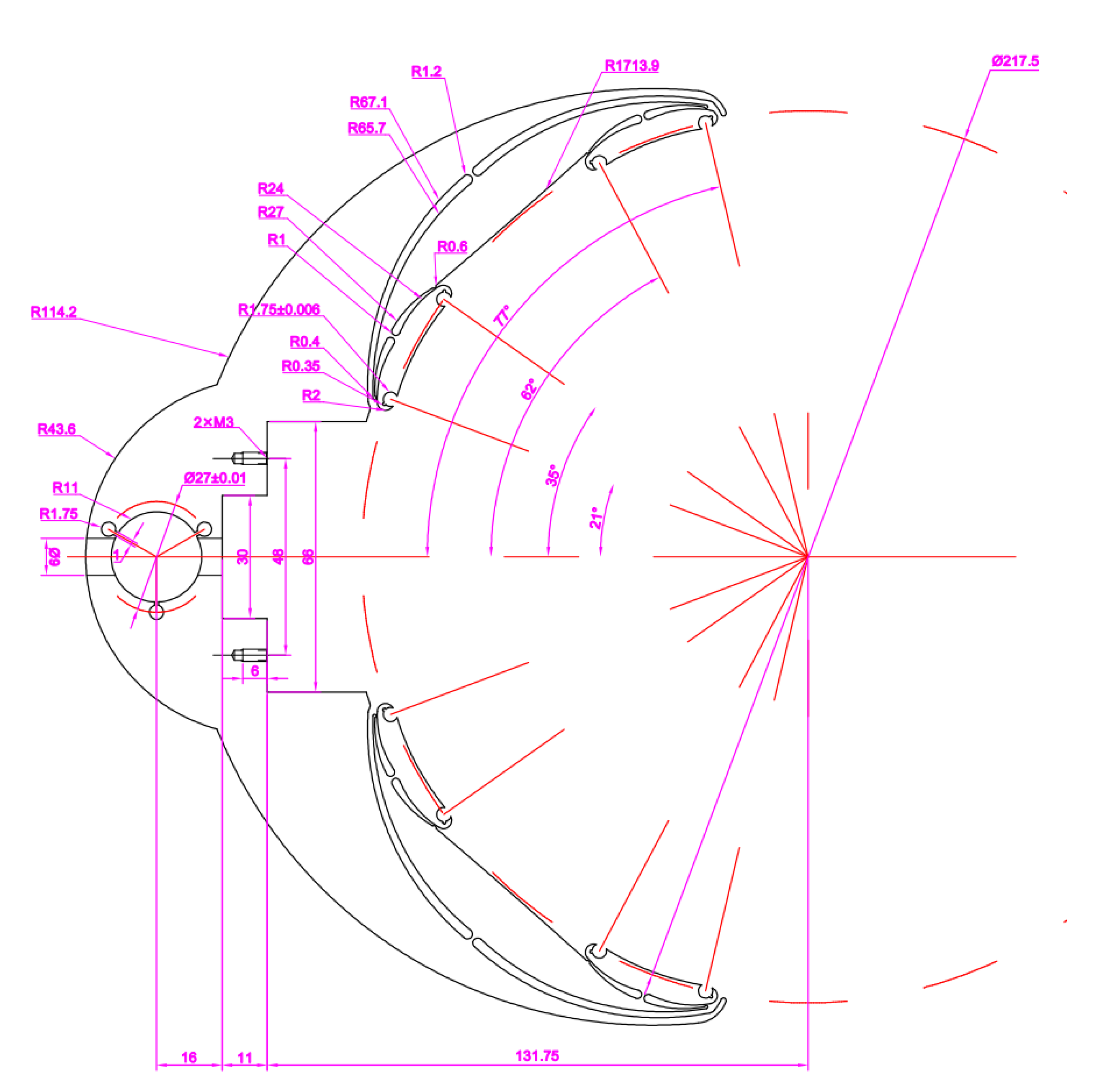
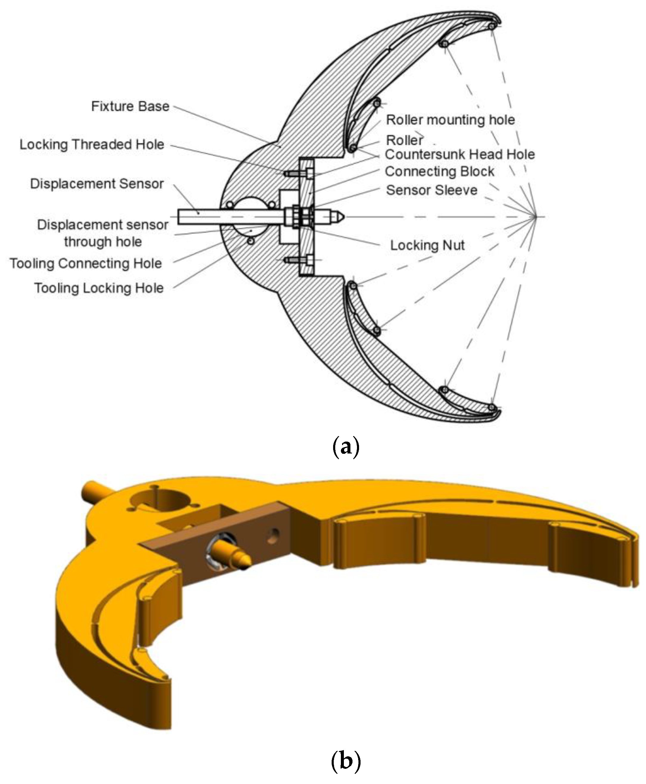
2.2. Adaptive Flexible Grinding Fixture Design

In view of the above defects and shortcomings of the traditional support block type centerless grinding fixture, such as insufficient support force, uneven distribution of clamping force, not adapting to large-size thin-walled bearings, complex structure, and inconvenient operation, and to better meet the requirements of bearing grinding, the structure of the electromagnetic centerless grinding fixture is improved and designed.
The working principle of the new adaptive electromagnetic centerless grinding fixture is similar to that of the previously analyzed electromagnetic centerless grinding fixture, which is mainly aimed at improving and designing the structure of the support block in the traditional support block-type centerless grinding fixture, which is called the fixture body, and the structure of the fixture body designed for this experiment is shown in Figure 3. The specific dimensions of the fixture are shown in Figure A1 in Appendix A.
As the traditional support block type centerless grinding fixture structure is complex and has inconvenient loading and unloading problems, the entire fixture body as far as possible uses the integrated design, which, while reducing the assembly error brought about by the cumbersome process of parts and components equipment, improves the loading and unloading efficiency in the process of machining, machining accuracy, and bearing rings. The machining system of the overall rigidity of the bearing ring adapts to the bearing ring, such as the thin-walled parts of the grinding process.
In view of the large size of the thin-walled bearings to be processed, the need for a more stable clamping method, and the concentration of the clamping force exerted on the bearing rings by the traditional support block type centerless grinding fixtures, the fixture body as a whole adopts a special stacked-layer design, which is similar to the flexible hinge structure of the “floating point” structure to connect the different layers of the structure, so as to provide better flexibility and reliability of the entire structure. The whole structure has better flexibility and reliability, and the original support block and the bearing ring between a contact point areexpanded to multiple contact points, providing multi-point mechanical contact for the whole system to provide higher dynamic stability.
At the same time, multiple rollers are installed on the first layer of the stacked structure to realize rolling friction and reduce friction, avoiding the contact stress concentration produced by the traditional support block type centerless grinding fixture on thin-walled bearing rings and reducing the deformation of the workpiece in the grinding process. The symmetrical design of the whole stacked structure makes the support force of the whole structure more balanced and stable and improves the load-bearing capacity of the stacked structure, making it able to withstand greater loads and impacts.
There are six “floating points” on the body of the fixture focusing on the center of the fixture matrix, which corresponds to the center of rotation of the bearing collar in the grinding process. Despite the change of the clamping point, the angle of focus of these “floating points” is always fixed. This design makes it easier to determine the position of the workpiece during setup, improves the accuracy of the entire grinding process, and makes the process more stable and geometrically stable.
In the context of internal grinding, as the grinding process progresses, the fixture exhibits an adaptive displacement variation function. This function enables the fixture to distribute the contact stress at the jaw evenly, thereby achieving a more intimate fit with the workpiece contact surface. When the grinding wheel is not in contact with the workpiece, the displacement curve detected by the adaptive flexible fixture is relatively regular. However, as the grinding wheel continues to engage with the workpiece over time, the displacement curve gradually stabilizes. It has also been observed that with increasing grinding duration, the magnitude of displacement variation diminishes progressively.
This analysis indicates that during the grinding process, the fixture’s adaptive displacement variation function plays a crucial role. It ensures that the contact stress at the fixture jaws is evenly distributed and maintains a more conformal contact with the workpiece surface as grinding continues.
At the same time, the fixture body has a tooling connection hole ring through the connection flange and fixture tooling connection, so that the fixture body can flexibly adjust the pitch angle, so that the scope of adjustment is larger, adjustment is more convenient, and the adjustment to the appropriate position can be through the tooling on the locking threaded holes lock. At the same time, the connecting flange is made of brass, and after locking, the fixture can have a small movement under a certain force, which can further avoid the deformation caused by too much force in the grinding process of the bearing collar.
The design of the fixture body also includes the installation of displacement sensors to facilitate the realization of thin-walled bearing collar roundness error in the subsequent study of online monitoring and more comprehensive monitoring of the thin-walled bearing collar grinding process. The whole set of the electromagnetic centerless grinding fixture device used in the experiment also includes the fixture body fixed on the machine tool. The structure of the whole set of the electromagnetic centerless grinding fixture device is shown in Figure 4; the fixture tooling is mainly composed of the following components: connecting flange, fixture connecting block on, fixture connecting block in, fixture connecting block under, connecting shaft, connecting block, support frame, and support connection. The locking threaded holes in the fixture connecting block can fix the pitch angle of the fixture body, and there are also threaded holes in the fixture connecting block corresponding to the adjustment slots on the fixture connecting block, so that the fixture can be adjusted in the radial feed direction, which is convenient for the fixture to be adjusted to the optimal machining position The support bracket is equipped with slots for connecting to the rollers, which is a transition fit for the rollers and is convenient for the replacement of the rollers while meeting the needs of the machining. The support bracket is also equipped with slots that are compatible with the support connection, so that the position of the support bracket can be adjusted through nuts and bolts to adjust the bearing collar to the optimal machining position and to effectively fix the bearing collar position. The dimensions of the other parts of the tooling, the size of the threaded holes, and the hole positions are designed according to the dimensions of the precision CNC grinding machine used in the experimental process to ensure that the bearing rings are in the optimal grinding position.
This research addresses the issue of hysteresis deformation control during the grinding process of precision rolling bearings by proposing a novel adaptive flexible fixture design. The aim of this design is to effectively suppress the hysteresis deformation of the bearing rings during the machining process, ensuring automatic positioning of the rings during rotation and thereby strictly controlling the roundness error of the rolling bearings within the tolerance range.
The designed adaptive flexible fixture employs a modular structural design and is primarily composed of core components such as the fixture base, rollers, connecting blocks, sensor sleeves, and locking nuts. The fixture base adopts a symmetrical, layered structure design with upper and lower sections, and it achieves a multi-degree-of-freedom adjustment through an innovative “floating-point” connection mechanism. Specifically, this structure features a hierarchical layout: the topmost level connects two secondary structures, and each secondary structure further connects to two primary structures. The entire system converges at a central “midpoint” through six distributed “floating-points”. This unique connection method significantly enhances the flexibility and adaptability of the fixture.
In terms of structural details, each primary structure is equipped with two open-ended roller installation holes. These through-holes extend throughout the entire fixture base and are used for precise installation of the roller components. The rollers make direct contact with the bearing ring to be machined, ensuring the accuracy of force transmission. To facilitate the installation of the rollers, a dedicated notch has been specifically designed at each roller installation hole.
The symmetrical axis region of the fixture base integrates a multifunctional structural module, which includes a displacement sensor mounting structure and a tooling connection structure. A through-hole is located at the center for reliable connection with the tooling system. Surrounding the central hole, three through-locking holes are evenly distributed in a circular pattern, with each locking hole connected to the central hole through a radial slot, forming an efficient clamping system. In the tooling connection area, a stepped square groove structure is provided, where the side wall of the larger square groove is equipped with dual-threaded holes specifically for the precise positioning and installation of the displacement sensor. Additionally, a through-hole for the sensor channel is provided on the side of the fixture base, offering an unobstructed measurement path for the displacement sensor.
This design scheme, through its innovative layered flexible structure and precise force transmission system, achieves high-precision control of the bearing ring machining process, providing an effective technical solution to enhance the machining quality of precision rolling bearings.

3. Modal and Stress Displacement Simulation of Adaptive Flexible Fixtures
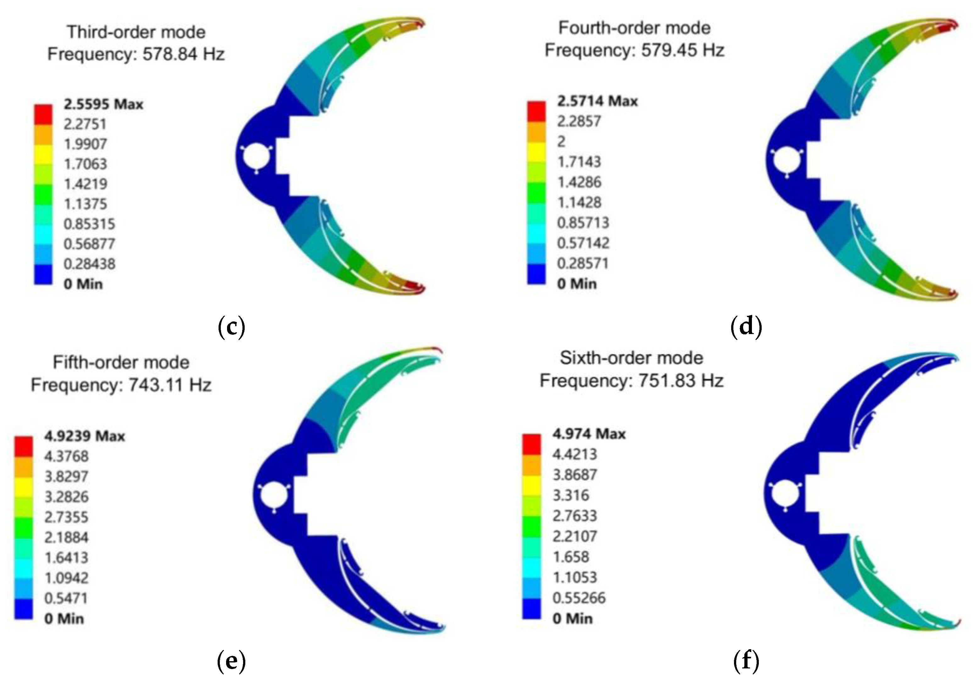
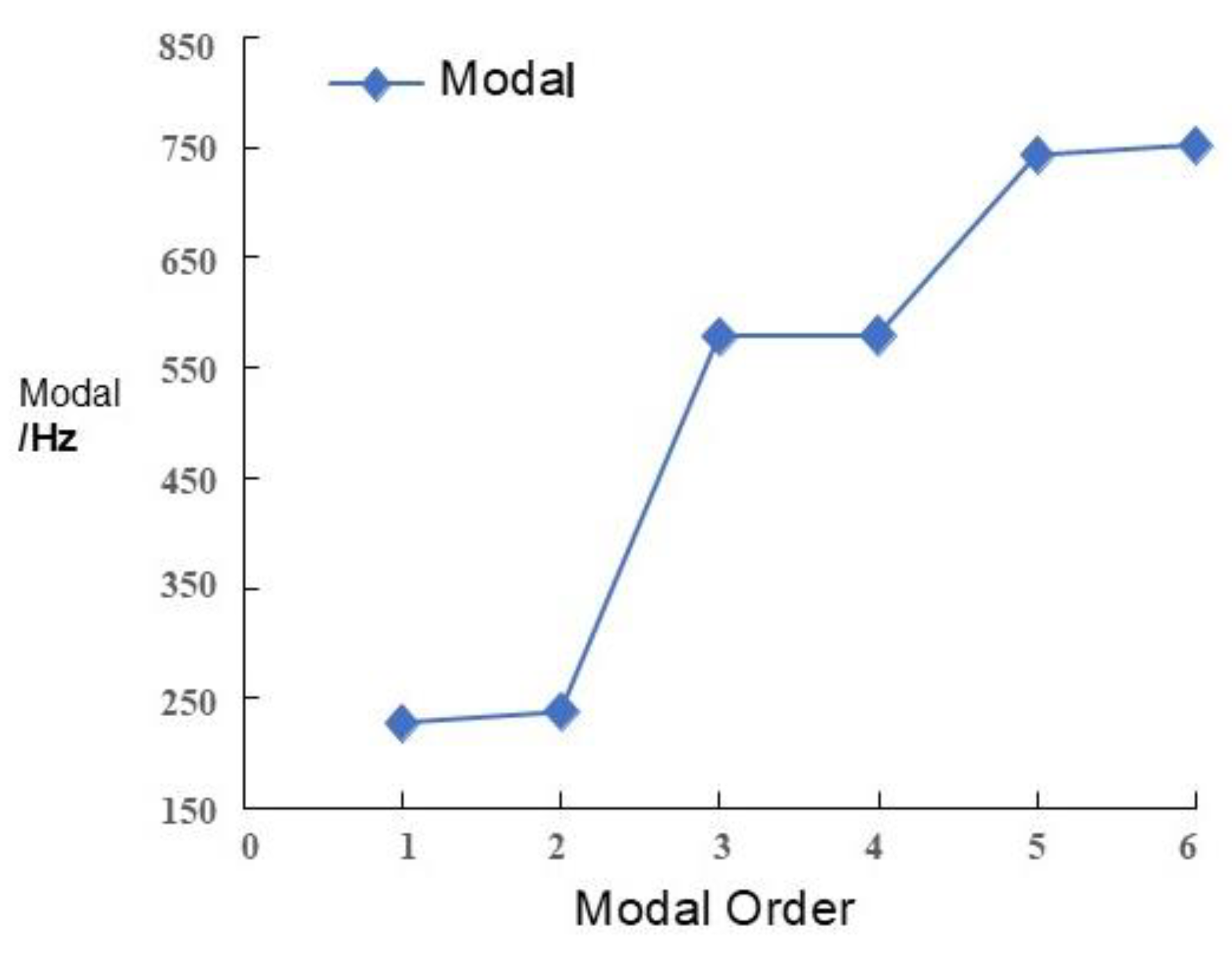
3.1. Modal Analysis

Modal analysis is an important means used to study the vibration characteristics of structures at different frequencies, and by analyzing the modal vibration pattern of a fixture, it can effectively predict the vibration that may occur during the machining process, so as to provide a theoretical basis for the design optimization of the fixture [31]. In the actual machining process, the fixture is usually subject to a variety of complex forces and moments, and these external forces may cause the vibration of the fixture, which in turn affects the machining accuracy.
In order to verify whether the structural design of the adaptive flexible fixture meets the machining requirements, ANSYS is used to model the adaptive flexible fixture and analyze the modal vibration patterns of the fixture in the constrained state. According to the state of the fixture in the actual use of the process, in the adaptive flexible fixture model, the displacement constraint (displacement) is applied to the center hole that is connected and fixed with the tooling, and the modal analysis is carried out, in order to simulate as much as possible the real situation of the grinding fixture in the actual processing. The material parameters of the adaptive flexible fixture are shown in Table 1, and the first six orders of mode shapes and modes after the model solution are shown in Figure 5 and Figure 6, respectively.
Combined with Figure 5 and Figure 6, the first order mode of the fixture is the lowest, which is 227.68 Hz, and the vibration pattern occurs at the upper end of the fixture at the tiger’s mouth. The second order mode is 237.45 Hz, and the vibration occurs at the lower end of the fixture. The third order modal change relative to the first and second order is larger, 578.84 Hz, and the vibration occurs in the fixture at both ends of the tiger. Generally, the workpiece speed of the bearing collar grinding process is below 100 r/min, its frequency is far lower than the first-order mode of the fixture, and there is no intersection between its modes, so the new grinding fixture can meet the requirements of the grinding process.

3.2. Stress-Displacement Analysis

The displacement and stress of the fixture’s vise will directly affect the macro-accuracy of the fixture. In order to simulate the displacement of the fixture to the thin-walled bearing and the displacement in the X direction under the actual working condition as well as to verify that the fixture has the function of adaptive correction of micro-motion, an orthogonal scheme considering the grinding force, the workpiece rotation speed, and the coefficient of friction is designed for simulation. The material properties of the simulation model are shown in Table 2, and the orthogonal experimental scheme is shown in Table 3.
Remote displacement is applied to the center hole of the fixture in the model to constrain the displacement of the hole centerline and the rotation of the structure around the hole centerline. According to the parameters of the grinding process, the tangential and axial forces are calculated. The grinding force is applied to the contact area on the surface of the workpiece, and the force is applied horizontally to the workpiece in the direction of the fixture. Additionally, the angular speed of rotation around the center is defined. The coefficient of friction is also defined. The grinding force, workpiece rotation speed, and friction coefficient are all imported into the simulation model. The model displacement and stress maps for the first set of parameter combinations are shown in Figure 7 and similarly for the other parameter combinations, and the final solution results are shown in Table 4.
From Table 3 and Table 4, it can be seen that the change in grinding force has a greater effect on the overall model displacement, X-direction displacement, and stress, and all three are significantly increased with the increase in grinding force. Under the same grinding force, the overall displacement, X-direction displacement, and stress of the model gradually decrease with the increase in workpiece speed. It can be seen that when using the new grinding jig for thin-walled bearing grinding, the increase in rotational speed will effectively reduce the total displacement and increase the grinding accuracy, which shows that the new grinding jig can effectively reduce the deformation of thin-walled bearings in the grinding process.

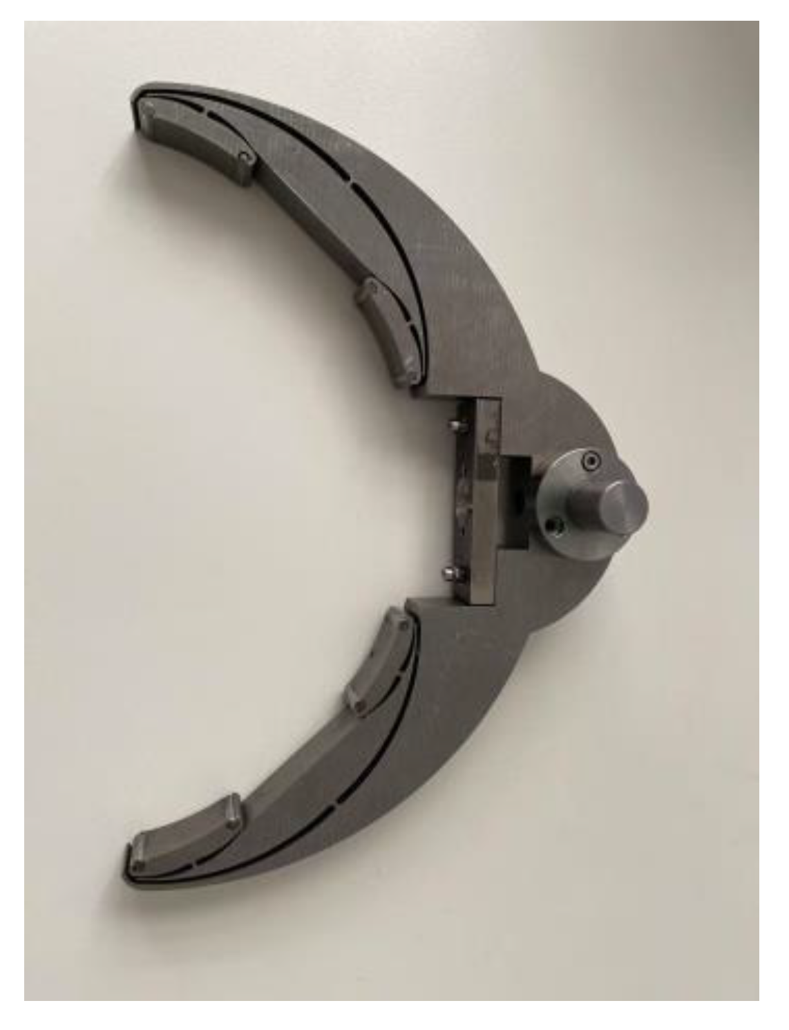
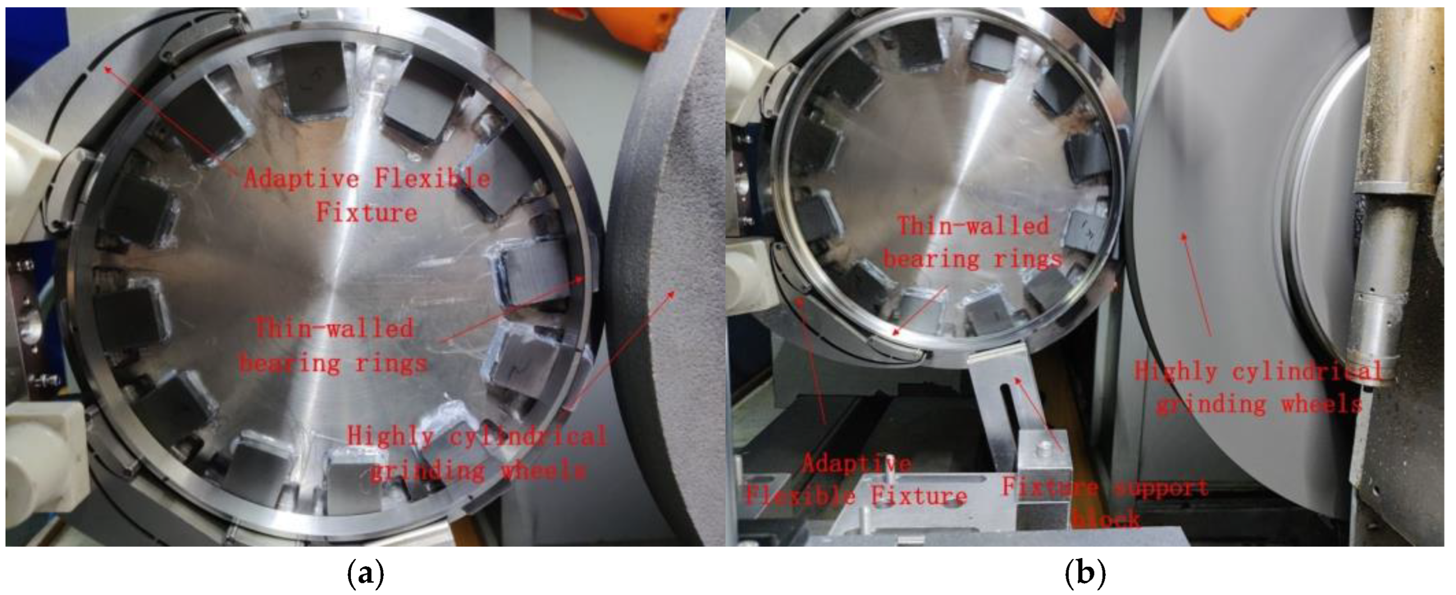
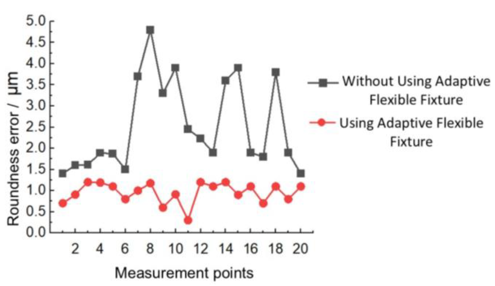
4. Adaptive Flexible Fixture Manufacturing and Roundness Error Analysis in Grinding Machining

The fabricated adaptive flexible fixture object is shown in Figure 8.
In order to quantify the roundness error of the adaptive flexible fixture, this paper carries out the cylindrical grinding processing and compares the roundness error before and after the use of the adaptive flexible fixture. The same grinding parameters were set: the grinding wheel speed was 30 m/s, the workpiece speed was 20 r/min, and the feed rate was 1 μm/min. The machining is shown in Figure 9, and the roundness results are shown in Figure 10.
According to the analysis in Figure 10, 20 points were collected for the roundness after machining, and the average error of roundness was 2.52 μm for the non-adaptive flexible fixture and 0.95 μm for the adaptive flexible fixture, while the difference between the highest and the lowest roundness error for the non-adaptive flexible fixture was 3.4 μm, and that between the highest and the lowest roundness error for the adaptive flexible fixture was 0.9 μm. By comparing the dispersion of the two, it can be seen that the dispersion of roundness after using the adaptive flexible fixture is reduced by 72.3%.
Comprehensive analysis of the above data indicates that the adaptive flexible fixture has an adaptive function for machining thin-walled bearing rings. Under the test conditions of a grinding wheel speed of 30 m/s, a workpiece speed of 20 r/min, and a feed rate of 1 μm/min, the thin-walled bearing grinding process achieves an improvement in roundness of 1.57 μm and a reduction in the degree of dispersion by 72.3%.

5. Conclusions

In this paper, a new type of adaptive flexible fixture is designed for the problems of easy deformation and difficult control of machining accuracy of thin-walled bearing rings in the grinding process. It aims to improve the machining quality and efficiency of thin-walled bearing rings by optimizing the fixture structure. The conclusions of this paper are as follows:
1. The working principle of the fixture is analyzed, and the fixture structure is optimized in combination with the machining characteristics of thin-walled bearing rings. The new adaptive flexible fixture adopts an integrated design, which reduces the assembly error and improves the loading and unloading efficiency and machining accuracy.
2. The fixture adopts a stacked design and a “floating point” structure, which increases the number of clamping points and improves the flexibility and dynamic stability of the fixture.
3. The design of the workpiece’s connecting hole ring and connecting flange on the fixture body enables the fixture to flexibly adjust the pitch angle, which avoids the deformation of the workpiece caused by excessive force.
4. The stability and performance of the new fixture are verified by modal analysis and stress-displacement analysis. The results show that the fixture can effectively reduce the deformation of thin-walled bearing rings and improve the machining quality and efficiency.
5. The roundness error analysis of the adaptive flexible fixture for grinding processing shows that the roundness of rolling bearing rings is improved by 1.57 μm; meanwhile, the dispersion of roundness error is reduced by 72.3%.
The new fixture provides a feasible solution for high-precision grinding of thin-walled bearing rings. However, the adaptability of the fixture for thin-walled bearing rings of different sizes and wall thicknesses needs to be further optimized. Existing adaptive flexible fixture designs are typically optimized for specific sizes and shapes of thin-walled bearing rings. When workpieces of different sizes or shapes need to be machined, the fixtures may need to be redesigned or adapted, which increases design and manufacturing costs. While adaptive flexible fixtures are effective in reducing workpiece deformation under static conditions, the dynamic stiffness and stability of the fixtures may be insufficient during dynamic machining processes, such as high-speed grinding.

Author Contributions

Conceptualization, J.Z. and Y.S.; methodology, Y.S.; software, B.C.; validation, Y.H., C.S. and M.W.; data curation, Y.S. and B.C.; writing—original draft preparation, Y.S., Y.H. and C.S.; writing—review and editing, Y.S., Y.H., J.Z., C.S., B.C. and M.W.; visualization, M.W.; supervision, C.S. and J.Z.; project administration, J.Z. and M.W.; funding acquisition, J.Z. All authors have read and agreed to the published version of the manuscript.

Funding

This work was supported by the Foundation of State Key Laboratory for High Performance Tools (GXNGJSKL-2024-09) and National Key R&D Program of Manufacturing Basic Technology and Key Components (2020YFB2009604).

Data Availability Statement

The raw data supporting the conclusions of this article will be made available by the authors on request.

Conflicts of Interest

Authors Yao Shi, Jun Zha and Chaoyu Shi were employed by National Key Laboratory of High-Performance Tools, Zhengzhou Abrasives & Abrasive Tools & Grinding Research Institute Co., Ltd. The remaining authors declare that the research was conducted in the absence of any commercial or financial relationships that could be construed as a potential conflict of interest.

Appendix A

The specific dimensional drawing of the fixture is shown below:
Figure A1. Specific dimensional drawings of fixtures, The dimensions shown in the figure are in millimeters (mm).
Jmmp 09 00139 g0a1

References

  1. Song, H.; Gao, H.; Wu, Q.; Zhang, Y. Effects of segmented thermal-vibration stress relief process on residual stresses, mechanical properties and microstructures of large 2219 Al alloy rings. J. Alloys Compd. 2021, 886, 161269. [Google Scholar] [CrossRef]
  2. Gašpar, T.; Kovač, I.; Ude, A. Optimal layout and reconfiguration of a fixturing system constructed from passive Stewart platforms. J. Manuf. Syst. 2021, 60, 226–238. [Google Scholar] [CrossRef]
  3. Krishnakumar, K.; Melkote, S.N. Machining fixture layout optimization using the genetic algorithm. Int. J. Mach. Tools Manuf. 2000, 40, 579–598. [Google Scholar] [CrossRef]
  4. Liu, H.; Wang, C.; Li, T.; Bo, Q.; Liu, K.; Wang, Y. Fixturing technology and system for thin-walled parts machining: A review. Front. Mech. Eng. 2023, 17, 55. [Google Scholar] [CrossRef]
  5. Gonzalo, O.; Seara, J.M.; Gurudeva, E.; Izpizua, A.; Esparta, M.; Zamakona, I.; Uterga, N.; Aranburu, A.; Thoelen, J. A method to minimize the workpiece deformation using a concept of intelligent fixture. Robot. Comput.-Integr. Manuf. 2017, 48, 209–218. [Google Scholar] [CrossRef]
  6. Wu, N.; Chan, K.C.; Leong, S. Static interactions of surface contacts in a fixture–workpiece system. J. Comput. Appl. Technol. 2014, 10, 133–151. [Google Scholar]
  7. Patalas, A.; Regus, M.; Peta, K. Studies of thin-walled parts deformation by gripping force during turning process on an example of bearing ring. In MATEC Web of Conferences; EDP Sciences: Les Ulis, France, 2018; Volume 244, p. 02010. [Google Scholar] [CrossRef]
  8. Chen, B.; Zha, J.; Cai, Z.; Wu, M. Predictive modelling of surface roughness in precision grinding based on hybrid algorithm. CIRP J. Manuf. Sci. Technol. 2025, 59, 1–17. [Google Scholar] [CrossRef]
  9. Chai, S.; Ouyang, L.; Bi, Q.; Yu, J.; Zhang, Y. An adaptive fixture for suppress vibrations and measuring workpiece deformation of thin-walled casings. Procedia CIRP 2021, 101, 322–325. [Google Scholar] [CrossRef]
  10. Li, Y.; Liu, C.; Hao, X.; Gao, J.X.; Maropoulos, P.G. Responsive fixture design using dynamic product inspection and monitoring technologies for the precision machining of large-scale aerospace parts. CIRP Ann. 2015, 64, 173–176. [Google Scholar] [CrossRef]
  11. Hao, Q.; Yang, Q. A self-adaptive auxiliary fixture for deformation control in blade machining. Int. J. Adv. Manuf. Technol. 2020, 111, 1415–1423. [Google Scholar] [CrossRef]
  12. Zhou, W.; Yu, F.; Zhang, J.; Huang, K.; Xu, Z.; Liu, X.; Ma, Y.; Feng, P.; Feng, F. An adaptive clamp system for deformation control of aerospace thin-walled parts. J. Manuf. Process. 2023, 107, 115–125. [Google Scholar] [CrossRef]
  13. Gandhi, M.V.; Thompson, B.S.; Maas, D.J. Adaptable Fixture Design: An Analytical Experimental Study of Fluidized-Bed Fixturing. J. Mech. Des. ASME Digit. Collect. 1986, 108, 15–21. [Google Scholar] [CrossRef]
  14. Wang, T.; Zha, J.; Jia, Q.; Chen, Y. Application of low-melting alloy in the fixture for machining aeronautical thin-walled component. Int. J. Adv. Manuf. Technol. 2016, 87, 2797–2807. [Google Scholar] [CrossRef]
  15. Jiang, X.; Zhang, Y.; Lu, W.; Gao, S.; Liu, L.; Liu, X. Characteristics of shear stress based on magnetorheological fluid flexible fixture during milling of the thin-walled part. Int. J. Adv. Manuf. Technol. 2020, 108, 2607–2619. [Google Scholar]
  16. Merlo, A.; Ricciardi, D.; Salvi, E.; Fantinati, D.; Iorio, E. Novel Adaptive Fixturing for Thin Walled Aerospace Parts. IOP Conf. Ser. Mater. Sci. Eng. 2011, 26, 012020. [Google Scholar] [CrossRef]
  17. Papastathis, T.N.; Ratchev, S.M.; Popov, A.A. Dynamics model of active fixturing systems for thin-walled parts under moving loads. Int. J. Adv. Manuf. Technol. 2012, 62, 1233–1247. [Google Scholar] [CrossRef]
  18. Bakker, O.J.; Popov, A.A.; Salvi, E.; Merlo, A.; Ratchev, S.M. Model-Based Control of An Active Fixture for Advanced Aerospace Components. Proc. Inst. Mech. Eng. Part B J. Eng. Manuf. 2011, 225, 35–51. [Google Scholar] [CrossRef]
  19. Kashyap, S.; DeVries, W.R. Finite element analysis and optimization in fixture design. Struct. Optim. 1999, 18, 193–201. [Google Scholar] [CrossRef]
  20. Ivanov, V.; Mital, D.; Karpus, V.; Dehtiarov, I.; Zajac, J.; Pavlenko, I.; Hatala, M. Numerical simulation of the system “fixture–workpiece” for lever machining. Int. J. Adv. Manuf. Technol. 2017, 91, 79–90. [Google Scholar] [CrossRef]
  21. Calabrese, M.; Primo, T.; Del Prete, A. Optimization of Machining Fixture for Aeronautical Thin-walled Components. Procedia CIRP 2017, 60, 32–37. [Google Scholar] [CrossRef]
  22. Andrews, A.; Abraham, P.; Rex, F.M.T. An Integrated Approach for Fixture Layout Design and Clamping Force Optimization. J. Sci. Ind. Res. 2022, 81, 1204–1216. [Google Scholar]
  23. Chen, C.; Zhang, P.; Xue, C. Test verification of emergency separation fuse pins for aircraft engines. J. Phys. Conf. Ser. 2022, 2368, 012036. [Google Scholar] [CrossRef]
  24. Hamedi, M. Optimizing workholding efficiency through fixture function simulation. Int. J. Prod. Res. 2005, 43, 2775–2788. [Google Scholar] [CrossRef]
  25. Kaya, N. Machining fixture locating and clamping position optimization using genetic algorithms. Comput. Ind. 2006, 57, 112–120. [Google Scholar] [CrossRef]
  26. Yang, B.; Wang, Z.; Yang, Y.; Qing, S.; Liu, C.; Gao, F. Multi-objective optimization of fixture locating layout for sheet metal part using Kriging, M.O.B.A. Procedia CIRP 2022, 112, 418–423. [Google Scholar] [CrossRef]
  27. Sikström, F.; Ericsson, M.; Christiansson, A.K.; Niklasson, K. Tools for Simulation Based Fixture Design to Reduce Deformation in Advanced Fusion Welding. In Intelligent Robotics and Applications; Xiong, C., Liu, H., Huang, Y., Xiong, Y., Eds.; Springer: Berlin/Heidelberg, Germany, 2008; pp. 398–407. [Google Scholar]
  28. Yu, K.; Wang, X. Modeling and optimization of welding fixtures for a high-speed train aluminum alloy sidewall based on the response surface method. Int. J. Adv. Manuf. Technol. 2022, 119, 315–327. [Google Scholar] [CrossRef]
  29. Siebenaler, S.P.; Melkote, S.N. Prediction of workpiece deformation in a fixture system using the finite element method. Int. J. Mach. Tools Manuf. 2006, 46, 51–58. [Google Scholar] [CrossRef]
  30. Hashimoto, F.; Gallego, I.; Oliveira, J.F.G.; Barrenetxea, D.; Takahashi, M.; Sakakibara, K.; Stålfelt, H.-O.; Staadt, G.; Ogawa, K. Advances in centerless grinding technology. CIRP Ann. 2012, 61, 747–770. [Google Scholar] [CrossRef]
  31. Gaygol, S.; Wani, K. Modal analysis of plate to analyze the effect of mass stiffeners using the Chladni plate approach. Mater. Today Proc. 2023, 72, 1314–1321. [Google Scholar] [CrossRef]
Figure 1. Schematic diagram of electromagnetic centerless grinding.
Jmmp 09 00139 g001
Figure 2. Support block type centerless grinding fixture.
Jmmp 09 00139 g002
Figure 3. Fixture body structure. (a) The two-dimensional drawing of the fixture body; (b) the three-dimensional drawing of the fixture body.
Jmmp 09 00139 g003
Figure 4. Structure of electromagnetic centerless grinding fixture device.
Jmmp 09 00139 g004
Figure 5. The first six modal shapes of the adaptive flexible fixture. (a) First-order mode shapes; (b) second-order mode shapes; (c) third-order mode shapes; (d) fourth-order mode shapes; (e) fifth-order mode shapes; (f) sixth-order mode shapes.
Jmmp 09 00139 g005aJmmp 09 00139 g005b
Figure 6. Adaptive flexible fixture first sixth order modes.
Jmmp 09 00139 g006
Figure 7. Contour plot of the model solution. (a) Modeled total displacement cloud; (b) model X-direction displacement map; (c) stress cloud at fixture floating point.
Jmmp 09 00139 g007
Figure 8. Physical drawing of adaptive fixture.
Jmmp 09 00139 g008
Figure 9. Adaptive flexible fixture roundness analysis experiment. (a) Structure of fixture clamping thin-walled bearing rings; (b) experimental setup for roundness error analysis.
Jmmp 09 00139 g009
Figure 10. Adaptive flexible fixture roundness comparative analysis.
Jmmp 09 00139 g010
Table 1. Material parameters of the new grinding fixtures.
MaterialDensities/
(g·cm−3)
Elastic Modulus/
(GPa)
Poisson’s RatioTemperature/
(°C)
stainless steel7.932000.2920
Table 2. Model material parameters.
PartsDensities/
(g·cm−3)
Elastic Modulus/(GPa)Poisson’s RatioTemperature/(°C)
Fixture
(Stainless steel)
7.932000.2920
Rolling
(Tungsten steel)
15.635300.3120
Workpiece (bearing steel)7.8122010.2720
Table 3. Three-factor three-level orthogonal experimental table.
NumberGrinding Force/NWorkpiece Speed/(rad·s−1)Friction Coefficient
151.050.01
252.090.02
353.140.03
4101.050.02
5102.090.03
6103.140.01
7151.050.03
8152.090.01
9153.140.02
Table 4. Solution results.
NumberTotal Displacement/
μm
X-Direction Displacement/
μm
Stresses/
Mpa
11.0030.254370.20583
21.00270.25410.20587
31.00230.253640.20593
42.00610.508830.41165
52.00580.508560.41168
62.00540.50810.41174
73.00910.763290.61747
83.00890.763020.6175
93.00840.762560.61756
Disclaimer/Publisher’s Note: The statements, opinions and data contained in all publications are solely those of the individual author(s) and contributor(s) and not of MDPI and/or the editor(s). MDPI and/or the editor(s) disclaim responsibility for any injury to people or property resulting from any ideas, methods, instructions or products referred to in the content.

