Review

Fatigue Damage Assessment and Lifetime Prediction of Short Fiber Reinforced Polymer Composites—A Review

by
Alexey A. Bogdanov
1,
Sergey V. Panin
1,* and
Pavel V. Kosmachev
2
1
Laboratory of Mechanics of Polymer Composite Materials, Institute of Strength Physics and Materials Science of Siberian Branch of Russian Academy of Sciences, 634055 Tomsk, Russia
2
Microelectronics of Multispectral Quantum Introscopy Laboratory of the R&D Center “Advanced Electronic Technologies”, National Research Tomsk State University, 634050 Tomsk, Russia
*
Author to whom correspondence should be addressed.
J. Compos. Sci. 2023, 7(12), 484; https://doi.org/10.3390/jcs7120484
Submission received: 18 September 2023 / Revised: 11 October 2023 / Accepted: 19 October 2023 / Published: 23 November 2023
(This article belongs to the Special Issue Recent Progress and Future of Polymer Composites)

Abstract

:
This paper reviews the findings in the area of fatigue damage assessment and lifetime prediction of short fiber reinforced polymer composites (SFRPs) under cyclic loading. It is shown that the direct methods of microstructure/damage inspection are the most sensitive and informative, while micro-computed tomography (μ-CT) is more laborious and possesses limitations in sample dimensions. Although the sensitivity of the indirect methods can vary, the most common one is based on stiffness reduction. It is shown that developing models of fatigue processes is impossible without assessing the degree of damage. The latter can be determined by stiffness reduction, the development of creep, or energy dissipation. Since fatigue mechanisms can differ, the most complete information can be obtained by combining these methods. The prediction results for fatigue life models based on plastic strain development showed the greatest agreement with the experimental results in comparison with other prediction models. In addition, some tasks are highlighted as the priority directions for the development of SFRPs and non-destructive testing (NDT) methods for their monitoring under fatigue.

1. Introduction

Polymer-based composites reinforced with high-strength fibers are widely applied in some high-tech industries [1]. For a long time, thermoset plastics (epoxy, polyester, phenol-formaldehyde, and other resins) were used as a feedstock for their matrices, reinforced with continuous fibers (fabrics) for improving strength properties [2]. Recently, thermoplastic binders have become widespread, allowing for the elimination of a number of shortcomings inherent in thermoset resins and the implementation of advanced production routes [3,4,5,6].
Short fiber reinforced polymer composites (SFRPs) do not possess strength properties comparable to polymer composites loaded with continuous fibers, but they are characterized by greater processability [7]. This fact enables them to be used for manufacturing a wide range of products, which inevitably experience cyclic loads in operation, leading to the development of fatigue processes. Such phenomena initiate primarily at interfacial boundaries due to a significant difference in the elastic moduli of the components. However, dimensions of discontinuities that can result in rapid failure are very small and cannot be detected by most non-destructive testing (NDT) methods [8,9]. Thus, understanding the fatigue failure mechanisms for SFRPs, as well as methods for controlling such changes, is of undoubted scientific and practical interest.
The use of high-performance polymers (HPP) as an advanced temperature/strength matrix can significantly expand the range of industrial applications for SFRPs. On the other hand, they are currently less popular in contrast to nanocomposites [10]. However, nanoparticles (fibers), as a single filler, do not improve strength properties to levels comparable to those loaded with short fibers, which are required for structural applications. The economic feasibility of their industrial applications is debatable as well [11,12]. One of the difficulties of using fatigue data of SFRPs, compared with composites reinforced with long fibers, is stated in the monograph [7]: “Since parts made of SFRP often possess a complex shape with, e.g., holes, rivets and inserts, fatigue cracks generally start from stress concentrations. Fiber orientation becomes various during injection molding, so data on fatigue of SFRP composites without taking into account anisotropy of properties are of limited use”.
SFRPs are a class of composites in which short fibers with a certain aspect ratio and orientation distribution act as reinforcements. In general, the stiffness and strength of a composite depends directly on the length of the reinforcing fiber—the longer the fiber length, the greater the stiffness and strength of a composite. However, short fibers present design flexibility; in general, shorter fibers provide wider possibilities to manufacture complex shapes [13].
The use of composite materials to replace metallic alloys has been growing in automotive and aeronautic industry. Injection-molded short fiber reinforced thermoplastics and especially reinforced polyamides have been widely used for structural parts [14]. Major advantages are offered by the injection molding technology in terms of design of complex geometries, high production output rates, good reproducibility, etc. [15].
Unfortunately, the attention paid to fatigue resistance in most short fiber composites is inadequate, even in fatigue-sensitive applications. Short fiber composites have several disadvantages relative to long fiber composites or neat engineering thermoplastics. Because of the presence of fiber ends, they are inherently inferior to continuous fiber systems in modulus and strength in the fiber direction, regardless of this, the differences can be minimal. In addition, they are more notch sensitive than continuous fiber composites. This depends on their type and gives rise to a problem with both broad scatter in properties (chopped strand) and lack of control over fiber length and orientation under injection molding. The impact strength of most tough thermoplastics is reduced by the addition of fibers, while the fracture toughness is usually maintained or even improved. Compared with continuous fiber systems, particularly unidirectional ply laminates, short fiber composites are much more likely to fail by the propagation of a single macroscopic crack, and so can be modeled in many cases using fracture mechanics and fatigue crack growth techniques adapted from metals technology [16].
Damages in SFRPs might be classified as follows [17]:
  • Interfacial debonding;
  • Matrix microcracking;
  • Interfacial sliding;
  • Fiber breakage;
  • Fiber microbuckling;
  • Particle cleavage;
  • Void growth.
SFRPs display a nonlinear stress–strain behavior under loading (both cyclic and monotonic). This nonlinearity is due to the nonlinear, both elastic and inelastic behavior of the matrix and fiber-based damage (fiber breakage and fiber-matrix debonding). Fatigue performance is determined by fiber orientation distribution, fiber length distribution, fiber volume fraction, loading frequency, environmental effects, mean stress and multiaxial loads, and notch sensitivity and stress concentration effects [13].
E-glass fibers are the most commonly used fibers in short fiber reinforced polymer composites. They are selected in the majority of applications because of their low cost, reasonably high modulus, and high tensile strength. The use of short carbon fibers is very limited, mainly because of their high cost. They are selected in applications for which their exceptionally high modulus is required to ensure high stiffness for the molded part. Carbon fibers are also used in a mixture with glass fibers in applications requiring low thermal expansion, high thermal or electrical conductivity, and resistance to electromagnetic interference.
Although metal fibers or metal-coated glass fibers are also used for shielding against electromagnetic interference, carbon fibers have the advantage of a much lower density. Short glass fibers are produced by chopping or cutting continuous glass fiber strands or rovings into lengths of 3.2, 6.4, 12.7, or 25.4 mm. Based on the strand diameter (not filament diameter), the fiber length to diameter (aspect) ratio of these chopped strands is estimated to be between 10 and 100. The shorter chopped strands are used for injection molding compounds, while the longer chopped strands are used for compression molding compounds. Short fibers are also called milled fibers, since they are obtained by hammer milling chopped strands into lengths smaller than 0.5 mm. Because of their extremely small aspect ratio, they act like particulate fillers rather than reinforcements in polymer matrix composites [18].
The purpose of this review is to summarize methods developed for assessing changes in the structure of SFRPs under cyclic loading. Considerable attention was paid to their sensitivity depending on both compositions and test conditions. It is stressed that the key challenges that make assessing fatigue damage in SFRPs difficult are: (i) small damage size, (ii) scattered pattern of their accumulation, (iii) variety of types of critical damages, (iv) fast rate of catastrophic failure without a pronounced main crack, etc. In addition, the effectiveness of their implementation for solving fundamental and applied problems was evaluated [19]. This review includes an analysis and comparison of models for the initiation and propagation of fatigue cracks in SFRPs [20]. As an applied aspect of the implementation of these methods, their applicability for both assessing the damage degree throughout the cyclic loading and predicting the residual life of SFRPs is considered.
In addition to the importance of solving the industrial NDT issues, the relevance of this review is lies in the discussion of the specifics of fatigue process development and failure for SFRPs. The key reason is the initiation and accumulation of scattered damages in the polymer matrix and/or at the polymer–fiber interfaces at the first fatigue stage, without a pronounced second one (propagation of a fatigue crack). So, methods for monitoring the mechanical state of cyclically loaded SFRPs must be sensitive to the development of structural changes in the polymer matrix, allowing for quantitative assessment. Nevertheless, dimensions of such damages are quite small for the vast majority of industrial NDT techniques, while the use of high-resolution methods such as X-ray diffraction is not sensitive and does not allow for their detection in the polymer matrix. In addition, fatigue failure mostly progresses through a scattered, distributed damaged zone rather than along a single dominant crack in SFRPs.
The mechanical hysteresis loop parameters are promising criteria for predicting fatigue life. For example, the loop area characterizes the amount of energy dissipation. Its higher level is often associated with a greater ability to resist cyclic loads [21,22,23]. In addition, a change in the rate of development of inelastic strains can be used as a criterion. In general, it becomes possible to predict fatigue life for any of the considered parameters, stiffness reduction, the creep development, AE or energy dissipation data, with a detailed study of the damage accumulation mechanism and identification of characteristic stages.
Despite the possibility of providing lower strength properties compared to those of composites reinforced with continuous fibers, it is expected that SFRPs will retain a significant segment in the market of polymer products [2,24]. In this way, the aspect of improving their fatigue life will be one of the determining factors [19].
The following tasks should be highlighted as priority areas for the development of SFRPs (not in order of importance):
8.
Designing composites based on the high-performance polymers [25,26,27,28];
9.
Reinforcement SFRPs with natural fibers [29,30,31];
10.
Improvement of interfacial adhesion, especially for high modulus carbon fibers [32,33];
11.
Fabrication of products from SFRPs using 3D printing with characteristic types and sizes of manufacturing defects [34,35,36];
12.
Implementation of SFRPs for biomedical applications [37,38];
13.
Hybrid reinforcement of SFRPs, including with micro- and nano-sized fillers [39,40].
When discussing the issues of fatigue damage assessment, the microstructural factors that give rise to fatigue damage in SFRPs are of critical importance. Among them are: (i) fibre–matrix interface, (ii) fibre length and its distribution, (iii) fibre preferential orientation, if any, (iv) fiber weight fraction, (v) polymer matrix compliance, etc.
In regard to the NDT applications for inspection/monitoring of SFRPs in the fatigue process, the authors suggest the relevant future development directions:
14.
Combination of non-contact (for example, DIC) and high-resolution (radiography, for instance) methods, as well as ones providing volume control of materials (e.g., the AE technique) [41,42];
15.
Implementation of terahertz radiation in industrial NDT procedures [43,44,45,46,47];
16.
Use of both synchrotron radiation and microtomography (mainly for fundamental and laboratory investigations) [48,49];
17.
Application of multiscale simulation methods, including for computational and experimental controlling of SFRPs [50,51,52].
In doing so, information about all available methods for assessing the fatigue damage of SFRPs will help researchers select the most appropriate method both for directly studying the fatigue behavior of SFRP materials, and for simulating these processes. Thus, this review is mostly focused on structural health monitoring application rather than fundamentals of damage mechanisms.
The review is structured as follows: (i) general considerations with an analysis of already published reviews on the topic; (ii) techniques for direct observation/detection of structural defects (for example, tomography, the digital image correlation (DIC) method, etc.) and changes in surface roughness; (iii) procedures for indirect assessment of such damages by changing mechanical properties or informative parameters of NDT methods (in particular, stiffness reduction, the development of inelastic strains, the generation of acoustic emission (AE) signals, etc.); (iv) models of the development of damages in the structure of SFRPs to predict their fatigue life (based on static tension data, as an instance). In addition, the criteria for predicting fatigue life based on the use of the above approaches are analyzed.

2. General Considerations

For SFRPs, fatigue damage and failure mechanisms have been investigated by many authors. One of the sophisticated reviews was presented by Talreja [42]. It showed that S–N (fatigue) curves are the basis for studying them. At the same time, the relevance of understanding such processes for predicting fatigue life was emphasized [53]. It was shown that the development of micro-damages (an increase in the density of cracks) in SFRPs occurs during several stages at different rates. To evaluate this, a linear relationship between stiffness and damages was applied. Three scale levels of the damage accumulation were identified with the corresponding approaches for their simulation: micro (continuous damage mechanics), meso (representative volume element) and macro. All of them are combined in the synergistic damage mechanics approach. As a conclusion, the need for further development of these algorithms was highlighted, taking into account the irreversibility resulting in damage accumulation. This enables the prediction of fatigue life using minimum empirical data. For these purposes, tools are required to control the development of damages, allowing for in situ assessment of their level and fatality. This fact also underlines the relevance of the current review on the analysis of existing methods for estimating damages developed in SFRPs under cyclic loading.
It was concluded by Quaresimin and Talreja [54] that methodologies for fatigue life assessment, which guarantee the safe operation of SFRPs, have not been fully developed so far, despite the widely studied behavior of SFRPs under uniaxial cyclic loads. In addition, this phenomenon is much less reported for multiaxial or variable amplitude loading, although this is important for designing structural elements due to the complexity of their actual operating conditions in most cases.
The published reviews dealt with fatigue damages in SFRPs focusing on the need for input parameters to develop a model. The brilliant generalization was proposed by Jain [13]: ”The fatigue behavior of SFRC depends on a large number of characteristics. Among them are fiber orientation distribution, fiber length distribution, fiber volume fraction, frequency, environmental effects, mean stress and multiaxial loads, and notch sensitivity and stress concentration effects”. Note that issues like anisotropy, variable response for different SFRP systems, and progression through diffuse damage versus localized cracks will influence sensitivity of damage assessment methods.
Fatigue simulation of SFRC required development of a hybrid multiscale approach that combines sample-level tests and simulation results on different scales: microscopic simulation and macroscopic fatigue behavior (multiscale). The fatigue strength calculations represent a more complicated problem since the effective stiffness can be interpreted as an average property, while the fatigue and strength properties are based on localized phenomena. The major event during fatigue loading is caused by fiber–matrix debonding, and matrix cracking becomes important only in the final stage of life. Thus, the models for predicting damage growth should be phenomenological with no emphasis on the fiber, matrix, or interphase behavior, nor should it require more than 20 input parameters, which are difficult to determine experimentally. There are also fatigue criteria based on strain rate and energy. A model of this kind should unify different mechanical parameters like apparent modulus, total strain energy density per cycle, anelastic strain energy per cycle, and axial mean strain, using a single factor.

3. Direct Methods for Damage Assessment

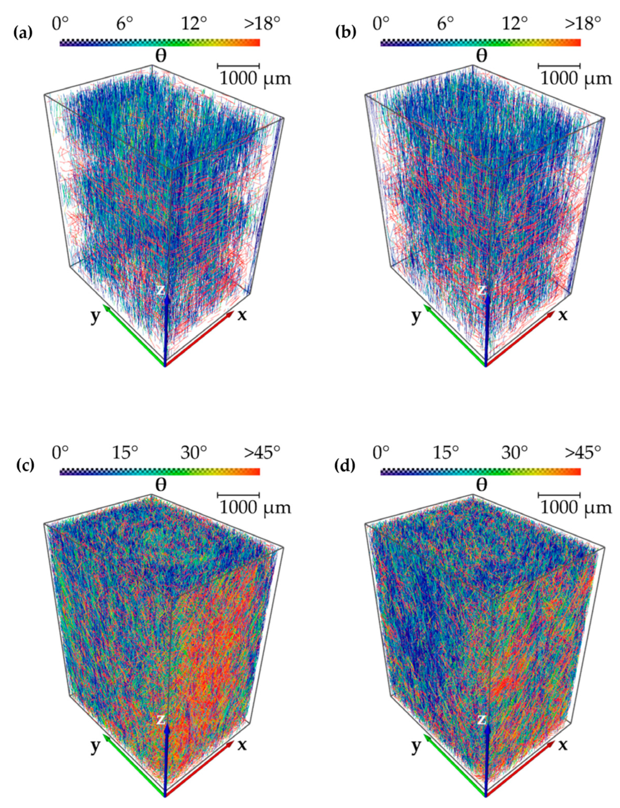
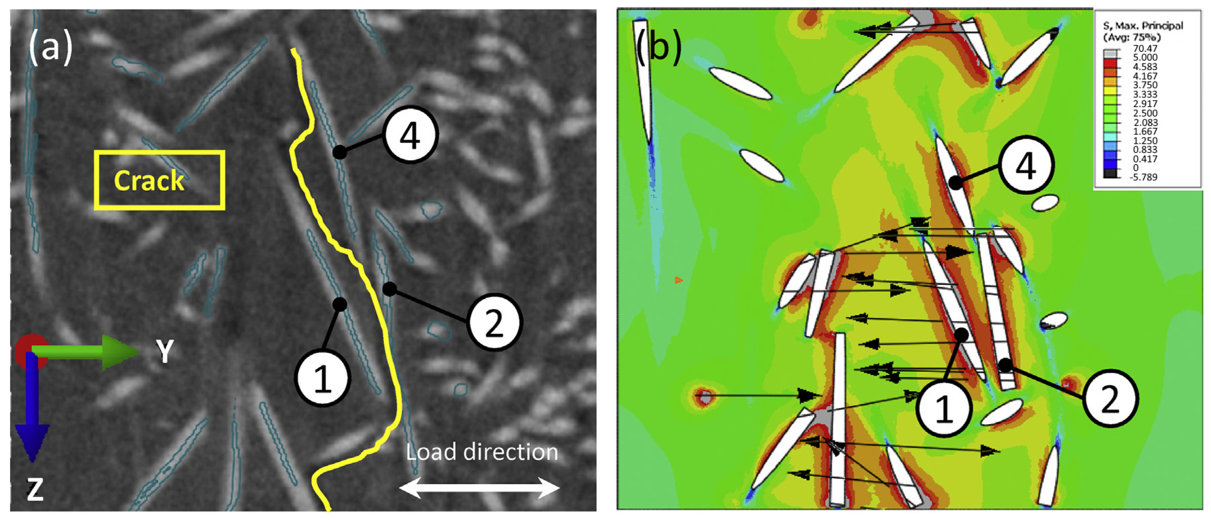
3.1. Computed Tomography

The detection of cracks and micro-damages in SFRPs or structures made of them is an important and non-trivial task. A conventional (destructive) method is optical microscopy, which makes it possible to obtain a 2D image with a crack in the form of a curve on their surfaces. The use of 3D imaging techniques, such as computed tomography (CT), enables the visualization of a composite structure as a 3D pattern (Figure 1). In this case, cracks are shown as locally planar structures, which can be described as 2D surfaces with a 3D relief. Data for such graphs are obtained using CT, which provides 3D visualization of materials with a resolution of up to a few microns, according to Krause et al. [55]. Martulli et al. have shown [56] that CT is one of the most effective methods for controlling damages in SFRPs, since it helps to obtain information about the microstructure in the bulk materials with a sufficiently high resolution. Synchrotron X-ray microtomography aids the study of the development of 3D discontinuities, to identify their elementary mechanisms, sequence, and kinetics. Rolland et al. have noted [57] that understanding the fatigue damage mechanisms for SFRPs is a key challenge for optimizing their manufacturing and proposing physically based multiscale simulation of such processes.
CT can realize real-time monitoring of fatigue damage during the fatigue test. In addition, it can effectively characterize the formation and development of fatigue cracks. General failure of SFRPs is characterized by matrix cracks and overall crack propagation whilst μCT is exploited to examine cross-sectional views showing detailed through-thickness matrix cracks distribution and 3D damage pattern. Fiber–matrix interfaces act as crack initiation sites, due to the presence of weak adhesion and stress concentrations at the ends of the fibers where fatigue damage and failure occurs [49].
The development of predictive models for fatigue behavior of materials is closely related to quantitative assessment of the phenomena of nucleation and propagation of damages. Conventional procedures applied for this purpose, including optical microscopy, radiographic inspection and ultrasonic methods, are either destructive or do not provide the required resolution. However, imaging techniques using synchrotron radiation and, in particular, X-ray microcomputed tomography (μ-CT), combine the advantages of NDT techniques with high spatial resolutions, according to Cosmi and Bernasconi [59]. A drawback of μ-CT is that only small samples can be examined compared to those characterized in industrial NDT procedures [60].
Bernasconi et al. have stated [61] that synchrotron light microtomography makes it possible to visualize local orientations of fibers in incised grooves, to analyze images of the internal structure of such samples in terms of the general morphological parameter and the average intersection length, as well as to calculate the strain fields assessed by the digital image correlation (DIC) method. By combining μ-CT and computer simulation using the finite element method (FEM), the elastic modulus can be determined in various directions in an open hole plate configuration with asymmetric fiber distribution, according to Ayadi et al. [62].
The damage development dynamics can be analyzed by μ-CT during periodic pauses in fatigue tests [58]. In these cases, the most characteristic discontinuities are debonding (loss of adhesion between fibers and a matrix along their interfaces), Figure 2, as reported by Arif et al. in [63].
In [64], Rudolph et al. have described an unconventional, small angle X-ray diffraction scattering technique, which was developed and applied to solve some NDT issues. In principle, this method is similar to X-ray imaging (in microtomography) but it is based on X-ray refraction. For this purpose, X-ray optical effects at micro-interfaces of SFRPs are employed. It is possible to detect the damage accumulation on internal surfaces as well as at interfaces with submicron resolutions due to a short X-ray wavelength of about 10–4 µm. Both cracks and pores of submicron dimensions are determined using X-ray refractometry without fracturing samples. Table 1 presents some summarized data on the CT methods implemented for analyzing fatigue of SFRPs.
Summary. In most cases, the CT method was implemented to evaluate fiber distributions in SFRPs reinforced with short glass fibers (GFs) at contents of about 30 wt.%. By using such a technique, cracks and delamination can be found in layered composites. In addition, fatigue damages can be assessed if microcracks and/or voids are observed. However, these results can be obtained only by testing small samples with synchrotron radiation sources. This fact hinders the use of this technique for solving a wide range of practically important problems, primarily in industrial NDT procedures. The CT’s spatial resolution limit is related to massive flaws at the fibre–matrix interface as well as cracking of individual fiber bundles. Thus, the flaws/damages of lower dimensions like matrix microcracking are out of CT technology resolution currently.

3.2. Visualization of Surface Damages

Blais and Toubal have shown [67] that the fatigue damage accumulation in SFRPs may be reflected on their surfaces. High-resolution imaging can be used to reveal the initiation and propagation of cracks as a function of the number of cycles. Visualization methods can be useful in studying the main fatigue crack behavior. For this purpose, brightness distributions are estimated near a notch using a brightness measurement system with a camera, according to Yamamoto and Hyakutake [68]. By combining a high-speed camera with the DIC method, quantitative information about local strains can be obtained; therefore, localized damages can be detected at relatively early fatigue stages, as reported by Palmstingl et al. [69].
On surfaces, fatigue damages can be analyzed quantitatively by monitoring the dynamics of changes in their roughness. For SFRPs, such an evolution is a qualitative indicator of the crack initiation and development, transforming into irreversible damages as they reach their surfaces, according to Casado et al. [70]. Thus, revealing the correlation between roughness and material fracture, micro-mechanisms enable the application of this parameter for assessing fatigue during the operation of various products, as shown by Casado et al. [71]. Klimkeit et al. have reported [72] that the propagation of a single macroscopic crack is not the main fatigue mechanism under cyclic loading. Such damages are spatially distributed in a material, so this phenomenon enables monitoring of the propagation of fatigue cracks using the method of periodic surface replicas. Table 2 presents some summarized data on the use of the surface visual inspection methods, the types of damages, and the compositions of the tested SFRPs.
Summary. A disadvantage of the surface visual inspection methods is their low resolution, which limits dimensions of the observed damages to the scale of macrocracks. Changes in roughness were detected only for high-cycle fatigue mode. Some observed pseudo-cracks, also changing the surface roughness index, were temperature-dependent and smoothed out over time after the test completion. Surface observation methods cannot detect subsurface damage not visible on the surface. Note that DIC as well as other popular NDT methods is slightly sensitive to the accumulation of fatigue damages in the bulk components, for the reason that low spatial sensitivity DIC is not able to detect very minor damages. In addition, surface observation has very limited capability to characterize internal damages as well. These methods are uninformative in terms of assessing the magnitude of scattered fatigue damages.

4. Indirect Methods for Fatigue Monitoring and Damage Assessment

4.1. The Stiffness Degradation

The dynamic modulus/stiffness reduction measurement is a widely used method for assessing the damage degree in composites primarily reinforced with continuous fibers. Arif et al. have noted [63] that the accumulation of scattered damages occurs throughout a sample upon fatigue testing, although they do not necessarily possess the same size and concentration in different areas over its volume. However, cyclic loading causes a continuous increase in the damage degree that is reflected in changes in the dynamic modulus (Figure 3). Subramanian and Senthilvelan have shown [74] that stiffness reduction during fatigue tests manifests itself differently for various materials, test schemes, and failure mechanisms. In some cases, no changes are observed at all.
In [76], Wäber has identified three stages in the development of fatigue damages with corresponding changes in the dynamic modulus of SFRPs: (i) firstly, short fibers are pulled out and transversely oriented ones (relative to the loading axis) are detached, which is accompanied by a rapid decrease in the dynamic modulus of the material; (ii) then, it decreases linearly; (iii) and finally, shortly before failure, damages are rapidly formed, dropping the dynamic modulus. It was also shown that the information content of the method is expanded when it is combined with the AE technique, for example.
The fatigue damage assessment method based on stiffness reduction was also combined with monitoring of plastic strains. To determine the relationship between damages and inelastic strains, the relative stiffness loss versus plastic strain increment curves were plotted for monotonic and cyclic loads. A sharp increase in both damage degree and plasticity was observed due to local effects of cyclic loading, which correlated well with the results of scanning electron microscopy (SEM) examinations of the fracture surfaces, according to Imaddahen et al. [77].
In [78], Nony-Davadie et al. have described the two-stage fatigue damage accumulation and have noted that some discontinuities, such as microcracks, were observed both between fiber bundles and within them. The formation of damages obviously depends on orientations of fibers relative to the loading axis. Sieberer et al. have shown [79] the possibility of approximating the data on stiffness reduction and fatigue damage accumulation in a reference sample on real products. Mansouri et al. have used stiffness reduction of SFRPs to investigate the fatigue damage kinetics, combining it with both macroscopic observation of cracks and microscopic examination of interfaces to determine damage mechanisms [80]. Table 3 presents some summarized data on stiffness reduction measurement methods for the fatigue assessment, the informative parameters, and the compositions of the examined SFRPs.
Summary. The fatigue monitoring method based on the dynamic modulus/stiffness reduction reflects the damage accumulation. Nevertheless, both test schemes and failure mechanisms depend on the examined materials, so such a reduction may not be registered at all. Therefore, this method is often combined with other ones (AE, plastic strains, hysteresis loss, etc.). Since the stiffness reduction method provides just an integral estimate of damage accumulation, small size or local damages might be not detected. In addition, strain hardening can take place under cyclic loading, which could also prevent reliable estimation of scattered fatigue damages.

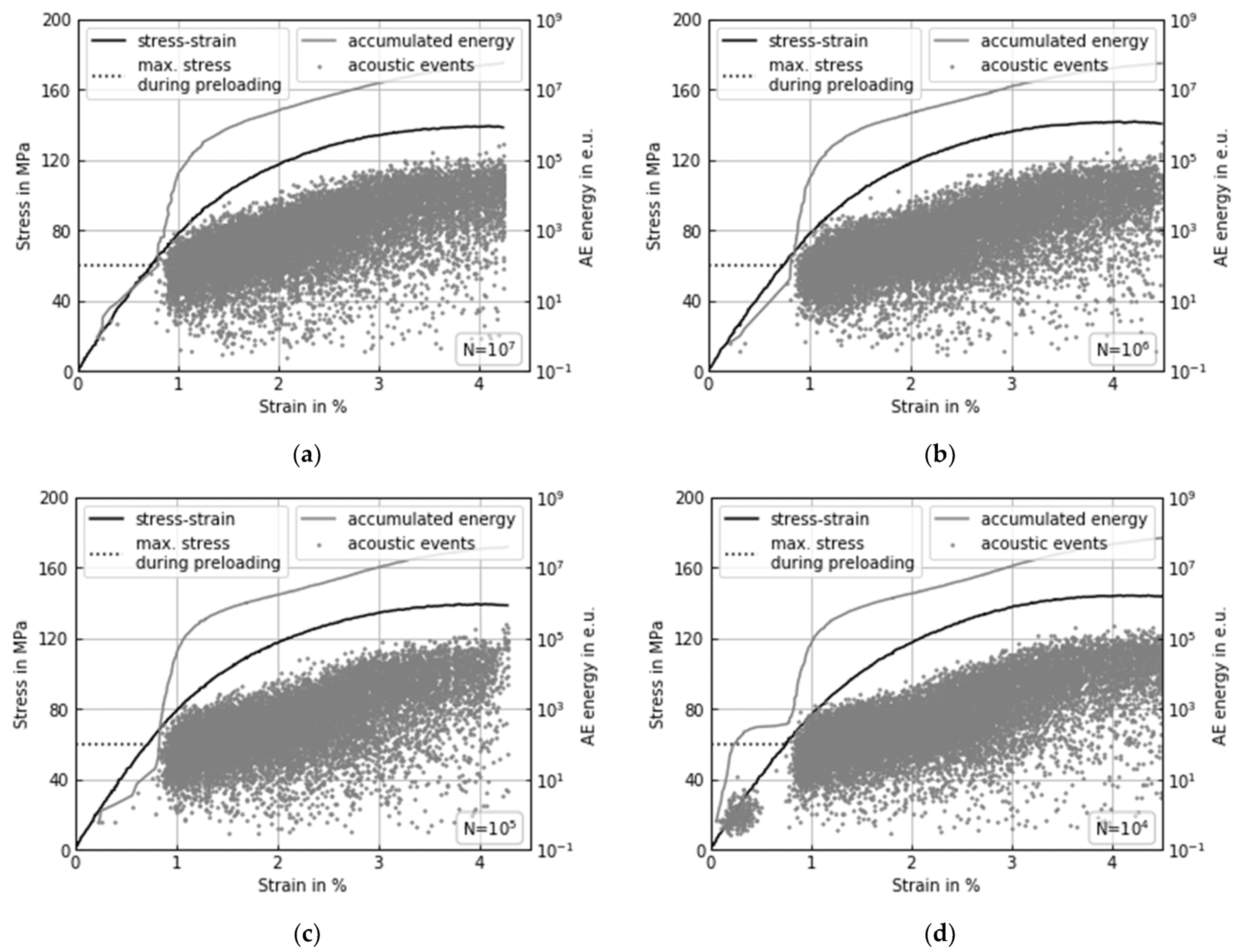
4.2. Ultrasonic Methods, including AE

Ultrasonic inspection methods for flaw detection in bulk materials have been used for a long time. In [87], Kasap et al. have reported the results of evaluation of thermal fatigue damages in SFRPs. In this case, changes in the speed of sound and the attenuation coefficient in the ultrasonic range depending on the damage accumulation were studied. The structural integrity of these samples was evaluated by determining the flexural strength after a series of thermal cycles using three-point bending tests. It was noted that both the acoustic wave velocity and the bending strength decreased, while the ultrasound attenuation increased with the rising number of thermal cycles. The reason for this is the damage accumulation in SFRPs, especially with debonding at the fiber–matrix interface. The ultrasonic inspection methods are actively implemented to evaluate such composites in operation since there is a good correlation between changes in the bending strength, the acoustic wave velocity, and the attenuation coefficient upon their thermal fatigue damaging.
Fatigue damages, estimated by the AE parameters, are characterized by the three-stage evolution pattern. For example, Wäber has shown [76] that pulling out short fibers and detaching transversely oriented ones leads to a high AE activity at the first stage. At the second stage, a constant AE activity (count rate) is observed. The third stage, corresponding to rapid damage accumulation, begins shortly before failure. It is characterized by a high activity of AE signals with greater peak amplitudes.
Krummenacker and Hausmann have compared AE signals during tests for assessing the residual strength of samples under cyclic loading with the data for undamaged samples [88]. The idea of this approach is based on the possibility of recording only those damages that were caused by the action of a cyclic load (i.e., they have a fatigue origin). Similarly, a threshold of stresses required for fatigue damages is determined by analyzing the AE energy, Figure 4.
Based on acoustic response (amplitude, energy, and time of flight), AE signals have been analyzed with a switched capacitor power converter under cyclic loading by Anaya-Ramirez et al. [83]. An algorithm was proposed for analyzing each acoustic event, as well as the contribution of each AE signal for different levels of fiber–matrix interfacial adhesion.
In [89], Suzuki et al. have investigated the effect of the loading direction and fiber content on the fatigue crack propagation by the AE method. The counting rate curve for AE events was divided into three stages, similar to those of the fatigue crack propagation. At the same time, fiber rupture was the dominant type of damage in all zones in samples with fiber contents of 15 and 45 wt.%. Table 4 presents some summarized data on the plastic strain development (creep) during fatigue tests of SFRPs.
Summary. The AE method is widely implemented in NDT procedures for assessing damages in SFRPs. However, since acoustic emission is a passive, non-destructive mean, it is slightly sensitive for detecting minor damage events. Thus, its application is more effective as a complementary one, i.e., in combination with other methods, due to its indirect damage assessment.

4.3. Energy Dissipation (Heat Release)

Yamashita et al. have noted [96] that the fatigue failure criterion, based on an assessment of the energy loss consumed (dissipated) for an irreversible change in the structure, is a common method of analysis. According to Arif et al. [63], the energy loss is determined by the mechanical hysteresis loop area, as well as its combination with changes in the dynamic modulus, strains and temperature. In addition, some other parameters that consistently complement each other for solving the problems of assessing damages in SFRPs are important.
To study fatigue processes in pure polymers, alloys, and composites, both mechanical work and heat generation can be measured, as well as the proportion of work contributing to the release of heat, which can be estimated under cyclic loading. It is believed that the greater the last parameter, the higher the fatigue life of polymers. It was experimentally shown that this parameter depends on the density of entanglement of polymer macromolecules. In this case, the polymer chains are intertwined with each other, and the heat released during their mutual friction does not lead to deformation of the polymer matrix. Hachiya et al. have reported [97] that fatigue life of both alloys and composites also depends on the structure at the interface between the components (phases) and especially on the interlacing and presence of a chemical bond in the interfacial region. Thus, the portion of work contributing to the release of heat can be analyzed for predicting fatigue life (Figure 5).
In [99], Casado et al. have proposed a model for identifying critical states by examining the evolution of various parameters under cyclic loading, namely both stored and dissipated energy, as well as the phase delay between load and strain signals. These parameters may indicate the fact that the material temperature has reached the glass transition level due to the internal heat released upon damage accumulation. Starting from this point, material strains continuously increase due to its damage, inevitably leading to fatigue failure.
A method based on evaluation of the energy generated per loading cycle for detecting fatigue-related damages was suggested by Carrascal et al. [100]. Lowering of mechanical properties is assessed using a damage parameter, defined as the change in energy per cycle with respect to the initial conditions. In the damage accumulation depending on the energy per cycle, three clearly differentiated zones can be distinguished:
  • An area of slowing down the energy rapid growth;
  • The linear damage accumulation, so its rate can be defined as a function of the potential of variation of the applied stress;
  • Accelerated damaging and failure.
Li et al. have developed a model for predicting the fatigue limit on S–N curves by combining thermodynamic laws and fatigue damage mechanisms [101]. In this case, the energy dissipated during a fatigue test is calculated by solving local thermodynamic differential equations based on changes in the sample surface temperature. Then, the intrinsic dissipation contributing to damage accumulation is evaluated, which is used to predict the fatigue properties.
Shiozawa et al. have stated [98] that both temperature changes and ΔTD are caused by variations in stress distribution conditions between fibers and resin due to damages caused by delamination. Therefore, the ΔTD value can be used for detecting delamination discontinuities and evaluating damage accumulation.
In [102], Meneghetti and Quaresimin have presented an experimental method that allows for the estimation of the energy parameter described above. It is applied to analyze the fatigue behavior of both smooth and notched samples. The adopted energy parameter shows a certain correlation with their fatigue strength, regardless of both shape and dimensions. The hysteresis energy density per cycle was used by Meneghetti et al. [103] to assess the fatigue damage index. The nature of such a mechanical energy was investigated in order to determine the extent to which dissipation is caused by the development of creep. It was shown that the hysteresis energy dissipated per material unit volume in a cycle due to viscoelasticity is negligible with respect to its total value.
The loss tangent (viscoelastic damping factor), hysteresis loop width, and displacement amplitude were reduced in fatigue tests of materials sensitive to the loading frequency, according to Eftekhari and Fatemi [104]. They have used the Larson–Miller parameter to determine a correlation between the recorded fatigue data, as well as to inter-compare the stress amplitude, frequency, cycles to failure, and temperature. For this purpose, an analytical model was developed for assessing strengthening effects of frequency, average stresses, fiber orientations, and temperature on fatigue life. Table 5 presents some summarized data on energy dissipation upon fatigue testing of SFRPs.
Summary. For SFRPs, the indicator of energy dissipation per hysteresis may characterize the ability to resist fatigue under cyclic loading, so its changes can be used as a fatigue damage index.

4.4. Plastic Strain Development (Creep)

Many authors have noted the relationship between the magnitude of residual strains and the number of cycles to failure. Solfiti et al. have shown [81] that plastic strains (or otherwise cyclic creep) are associated with damage accumulation in materials. Hiwa et al. have reported [108] that fatigue damages in SFRPs develop through initiating and propagating interfacial separation at fiber ends, as well as increasing permanent strains caused by pulling out fibers.
In [109], Noda et al. discussed nonlinear viscoelasticity. It was stated that, depending on whether the T temperature upon fatigue testing was below or above the Tg glass transition level, the fatigue process proceeded with the following steps: (1) damage begins with the formation of voids at the fiber ends; (2) microcracks propagate from the fiber ends at TTg or microcrack propagation is accompanied by debonding on their surface at T > Tg; (3) cracks propagate from the fiber ends in a brittle manner at TTg, or the crack edges predominantly remain bonded by bridges at T > Tg, which develop according to the plasticity mechanism; (4) cracks propagate rapidly when they reached critical sizes, resulting in the specimen failure.
Alexis et al. [110] reported that the study of fatigue and the assessment of fatigue life can be carried out using the mean strain, which reflects the development of plastic deformation, Figure 6.
In [77], Imaddahen et al. have shown a correlation between creep and stiffness reduction by combining methods of assessing fatigue damage accumulation. This result was confirmed by SEM analysis of the fracture surfaces. Raphael et al. have proposed to consider the rate of cyclic deformation and the amount of inelastic energy, which are used to predict fatigue life, as a damage criteria [111]. Komatsu et al. have estimated the degree of nonlinearity of dynamic viscoelasticity through the nonlinear viscoelastic parameter, which is calculated from coefficients of the extended Fourier series of the response signal during a fatigue cycle [112]. Nonlinear dynamic viscoelasticity increases as fatigue damages develop.
Creep strain stages were determined and related to stress cycles, service life, mechanical properties, and cyclic stress levels by Ahmadzadeh and Varvani-Farahani using linear and non-linear functions [113]. These authors have noted that the overall damage is caused by creep and fatigue accumulation under cyclic loading. Table 6 presents summarized data on plastic strains (creep) upon fatigue testing of SFRPs.
Summary. For SFRPs, the development of creep as a result of cyclic loading is closely related to fatigue damage accumulation. However, separating its contribution from the input of the plastic strain process is not an easy problem to solve. To predict fatigue life, the cyclic deformation rate can be used, which, given the known parameters of the stages of its development, makes it possible to control the failure process.

5. Fatigue Prediction Models

Reliable simulation of both fatigue and damage accumulation processes occurring in SFRPs is critical to their efficient industrial applications. At present, it is also crucial for particulate composite polymers operated in the high-cycle fatigue mode. Previously, an effective approach for analyzing fatigue of metals and alloys was developed via understanding their microscopic behavior (crack initiation and propagation) and bringing it to the level of macroscopic consideration (analysis) by combining with relevant test data (S–N fatigue curves, etc.). Similar approaches can be applied to SFRPs. In particular, Jain et al. have reviewed the fatigue simulation results for fiber-reinforced polymer composites [118], including (i) the microstructure analysis, (ii) the development of efficient multi-scale numerical simulation algorithms, (iii) structural studies, and (iv) detailed fatigue analysis. Later [13], Jain has summarized the reported observations of the damage development in SFRPs upon fatigue processes and various attempts to simulate them with an emphasis on the input parameters necessary for numerical calculations. They were determined from the hysteresis loop, including (i) the apparent modulus, (ii) the mean strain, (iii) the strain energy and (iv) the anelastic energy.
In general, such reported data can be assessed as the development of methods based on the experimental determination of the indirect damage parameters discussed above. This includes simulation of stiffness reduction, the development of inelastic strains, energy dissipation, etc. Various models for predicting the fatigue failure (S–N curves) are based on these parameters and the results of static tests (discussed in more detail below). Such models make it possible to predict S–N curves for different asymmetry coefficients using minimum experimental data, time, and financial costs.
Note that the cohesive zone model is usually utilized as a fracture propagation criterion when studying the single main crack. At the same time, it is hardly used efficiently when simulating scattered damage in SFRPs.

5.1. Based on the Results of Static Tests

In [119], Kabir et al. have proposed a model of micromechanical fatigue damage based on a statistical law of microscopic failure. For SFRPs, it is described by both fracture of fibers and their debonding from a matrix. Numerical methods were implemented to predict these two failure processes. Such simulations were carried out using a three-dimensional model containing elementary cells. The Weibull damage law was implemented to simulate the development of microscopic damages in SFRPs, taking into account the volume fraction of fibers and their orientations (0° and 90°). By comparing the simulation results with the experimental stress–strain curves obtained in tensile tests, the damage parameters for the Weibull model were determined. Using these damage parameters, a mesoscopic model was developed for SFRPs filled with 8.1 vol.% glass fibers and their damages were predicted under cyclic loading. An example of a damage development model through fiber debonding is shown in Figure 7.
Bourgogne et al. used the similarity of the mechanical behavior of SFRPs subjected to quasi-static loading and fatigue testing [120]. The aim was to predict the Weller curves as a function of temperature and water absorption. The model was validated using an example of reinforced PA6 under high humidity conditions, since the existing methods could not be applied in this case.
The solution of these problems possesses obvious practical applications. Thus, predicting the fatigue life of real automotive parts is a difficult problem due to the high variability of the possible microstructures in SFRPs that depend on the material flowing in the thermoforming process. In [121], Laribi et al. implemented a two-stage microstructure inspection principle based on an original ultrasonic method. They analyzed damages of four characteristic microstructure configurations under both static and cyclic loading. In all studied cases, these experimental data correlated well with predicted Weller curves at three operating temperatures.
A two-parameter model based on the strength reduction has been developed by D’Amore and Grassia [70]. Its predictive capability was validated using reported fatigue life and residual strength data. The simulation approach explicitly considered the maximum applied cyclic stress and the cycle asymmetry. This enabled the reduction of the amount of such experimental data required to predict the strength degradation kinetics from cycle to cycle. The implemented approach showed that both fatigue life and residual strength are related to the pattern of static strength distributions.
The accuracy of prediction results for fatigue life models based on results of static tests show very good agreement between experimental and numerical results, confirming the validity of this approach.

5.2. Based on Experimental Fatigue Curves

In [122], a range of analytical and empirical models for predicting the fatigue behavior of SFRPs under various conditions has been developed by Fatemi et al. based on an analysis of experimental data. They discuss empirical equations that characterize self-heating under cyclic loading. Kawai et al. have shown [123] that types of S–N curves significantly depend on cycle asymmetry, so the fatigue degradation proceeds most rapidly at its critical value, regardless of the test temperature. By using temperature as a parameter, an anisomorphic approach to the fatigue life diagram made it possible to adequately predict fatigue life and, therefore, the S–N curve over various medium stresses at any temperature within the studied range.
D’Amore et al. have developed a two-parameter model based on strength reduction considering both the average load and the applied load range [124]. This enabled the analysis of changes in strength of SFRPs during fatigue tests. In [125], Amjadi and Fatemi have proposed a critical plane damage model for predicting the fatigue life in both tensile–tensile and tensile–compression tests, taking into account both fiber orientations and medium stress effects. The influence of both temperature and frequency was also taken into account by transferring the proposed damage model into the general fatigue model. The mean stress parameter was also used for predicting fatigue life by various other authors (Eftekhari and Fatemi [126], Mortazavian and Fatemi [127], Amjadi and Fatemi [128]).
A method for predicting strain–fatigue life curves using stress fatigue data obtained under controlled loading was described by Mortazavian and Fatemi [129]. They also presented a model for evaluating fatigue life based on a comparison of data recorded at various fiber orientations, cycle stress ratios, and temperatures.
In [130], Pietrogrande et al. proposed a special fatigue life criterion, which is based on an assessment of the effective stresses acting in the most critical regions of a matrix (near both ends and side surfaces of fibers) at the crack pre-initiation stage. A multiscale (macro–meso–micro) procedure was implemented to estimate local stress distribution in SFRPs. It was shown that this criterion enables the assessment of the influence of the microstructure (namely, contents of fibers, their distributions, and their orientations), as well as loading directions. Jain et al. implemented a method in which the master S–N curve for a particular fiber orientation distribution was used to predict the fatigue life of a component of SFRPs [131]. This method combines data on damages at the microscopic level with the macroscopic fatigue properties.
The FEM is widely used for simulating the deformation behavior of SFRPs. Such components are characterized by nonuniform distributions of fibers in various areas. This leads to different levels of their static and fatigue strength. Jain et al. have stated [132] that each element can be simulated using the FEM as a representative volume element to account for such variations. In this case, both static and fatigue properties should be calculated for each of these elements. Further, a hybrid multiscale method for predicting S–N curves for each section of SFRPs was developed. It is based on a combination of micromechanics and experimental test results (taking into account microscale damages associated with macroscale fatigue properties). Later [133], Jain simulated local S–N curves considering the multi-axis pattern of applied loads. Primetzhofer et al. analyzed the local behavior in all sections of locally loaded SFRPs (but not only in critically affected ones), which set this approach apart from similar others [134].
Hoppel et al. have developed a model of the Palmgren-Miner cumulative damage accumulation, which predicts fatigue life under block loading with different amplitudes [135]. Similar simulations have been carried out by Noguchi et al. [136]. In [137], Laribi et al. have used a local failure criterion based on the critical damaged state, enabling the prediction of fatigue life under variable loading amplitudes considering the microstructure parameters. Dick et al. have shown the possibility of expressing model parameters as a function of one variable, namely the skewness coefficient [138]. The paper demonstrates the possibility of expressing each of the model parameters as a function of a single variable that is stress ratio, maximum stress level, or a material-dependent constant. In addition to S–N curves, FEM-based models have been developed by Yu et al. [139] to predict dependences between strains and the number of cycles.
Another model has been proposed by Pantano et al. [140] that can be implemented to predict the fatigue characteristics of SFRPs based on the results of SEM analysis of their fracture surfaces and some other experimental fatigue data. In [141], Chen et al. have developed an original probabilistic micromechanical damage model. It takes into account the multi-strain mechanisms and is based on a modified Mori–Tanaka method, as well as transformation field analysis to predict monotonic and low-cycle stress–strain reactions in SFRPs. The model enables the simulation of real orientations of fibers after their fabrication using the injection molding method. Such SFRPs are characterized by an arbitrary proportion of randomly oriented fibers.
Batu and Lemu have shown [142] that the use of simulation approaches in the design of turbine blades enables the development of SFRPs with reduced weight and improved fatigue life compared to those based on an epoxy matrix of reinforced GFs. Eftekhari and Fatemi have stated [143] that models based on linear damage accumulation provide satisfactory accuracy for block loading with different amplitudes, frequencies, and overloads. In [144], Nishikawa and Okabe have simulated cracks in a polymer matrix considering the microscopic fatigue process based on the Kachanov-type damage evolution law. The simulation results showed that the dependence of the damage accumulation on orientations of fibers noticeably changes the fatigue life of SFRPs (Figure 8).
After the injection molding process, orientations of fibers greatly affect mechanical properties of SFRPs. Kim and Kim have noted [145] that the use of the Digimat model with mean-field homogenization methods enables the description of the microstructure of SFRPs, including both the lengths and orientations of fibers. This made it possible to implement various simulation options for SFRPs with both linear and nonlinear deformation response. Some factors, such as relative stress gradients and orientations of fibers, were considered when analyzing fatigue of SFRPs. In [146], Shokrieh et al. have developed a model for predicting the fatigue life of composites reinforced with hybrid chopped fibers and nanoparticles. It was based on experimental data for similar composites without the nanoparticles. Avanzini et al. have shown [147] that one could simulate fatigue in rolling contact tests. Another model, proposed by Zhang et al. [148], was based on incorporating a cohesive zone into the fiber–matrix interface. In this case, the interfacial delamination behavior was taken into account.
The accuracy of prediction results for fatigue life models based on S–N curves show good correlation (86% within a factor of 3 and 93% within a factor of 5).

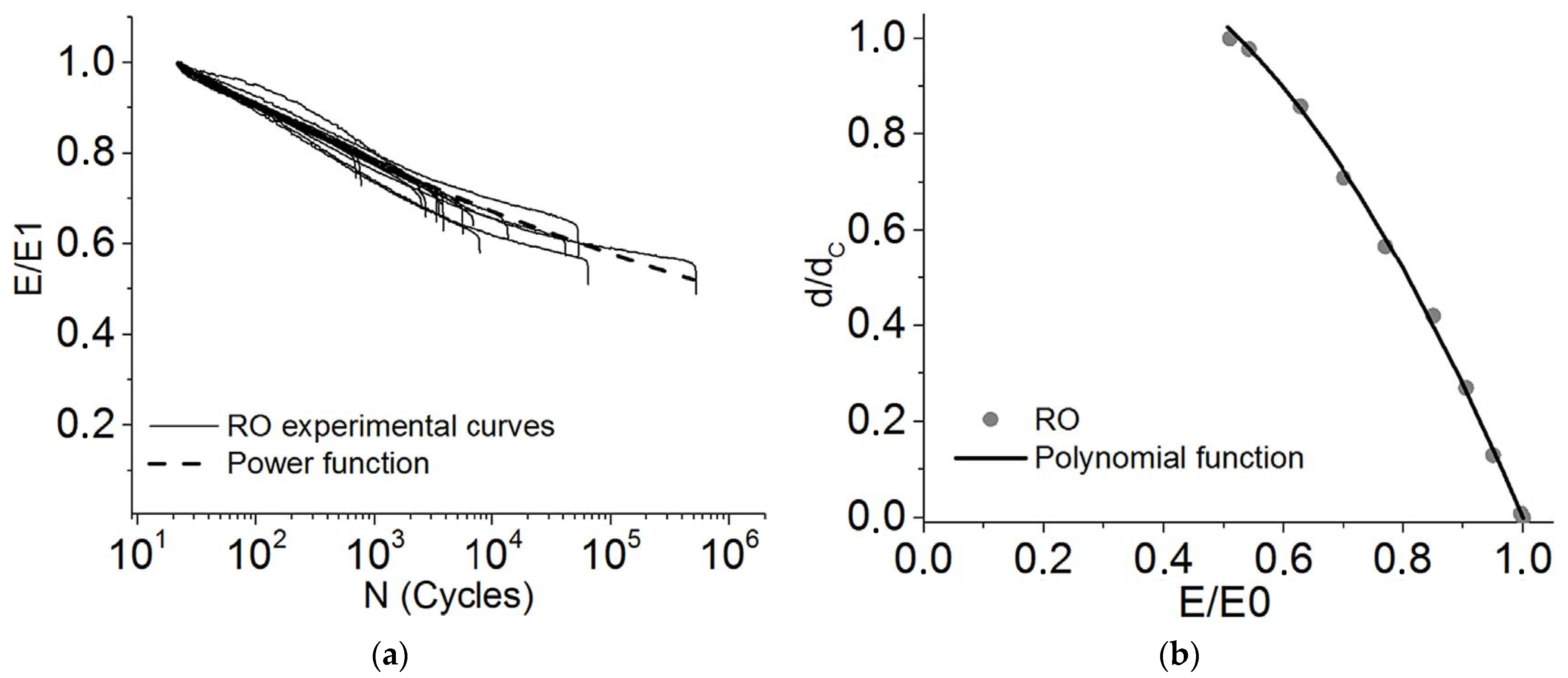
5.3. Based on the Stiffness Degradation

Magino et al. have developed a model of stiffness reduction by implementing a multiscale computational approach [149]. This made it possible to reduce the required mechanical tests to a minimum. The model’s ability to reproduce the experimentally revealed stiffness reduction was demonstrated for various orientations of fibers, stress amplitudes, and the cycle asymmetry coefficient in the range from −1 up to 0, as well as various incised grooves.
In [75], Laribi et al. have assumed that both monotonic and fatigue behavior of SFRPs are greatly determined by local damage formation. An approach based on the Mori–Tanaka micromechanical model was developed for describing the state equation. This enabled the relation of the rate of local damages to the level of macroscopic residual stiffness. The experimental stiffness loss and model simulation are presented in Figure 9. The generalization of this approach to a multiscale description of fatigue damages allowed for the plotting of an S–N curve for each considered microstructure. It is important that only a limited amount of experimental data is sufficient to implement the approach.
Köbler et al. have simulated stiffness reduction for SFRPs under cyclic loading by implementing a simple isotropic fatigue damage model [150]. In this case, the minimum number of model parameters and the assumption of a linear elastic reaction of fibers were applied. The stiffness reduction was determined for a fixed damaged state using a standard linear elastic homogenization procedure. In [151], Samareh-Mousavi and Taheri-Behrooz proposed a model combining stiffness reduction with the creep development. This made it possible to separate failure mechanisms. It was shown that the average strains are dominated by the fatigue process at high stress levels in a cycle. However, they are mainly controlled by the development of time-dependent viscoelastic strains at lower values.
Sul et al. have developed a model based on the stiffness reduction of composites filled with chopped fiber mats [152]. Shokrieh et al. have advanced existing models of stiffness reduction [153]. Their model predicts the bending stiffness reduction for SFRPs at different levels of applied stresses at room temperature. In [154], Brighenti et al. have presented another micromechanical model. In this case, degradation of mechanical properties was introduced as a criterion of fracture mechanics, which makes it possible to study the separation of fibers from a matrix. The process is considered as the 3D crack propagation, deteriorating properties at the interface. The μCT images of such defects are shown in Figure 10. Tamboura et al. have reported the results of simulation of both fatigue life and residual stiffness for SFRPs subjected to thermomechanical loads [155]. For this purpose, they used quantitative estimates of the evolution of the local damage rate for each loading block.
In [156], Nouri et al. have conducted phenomenological simulations of nonlinear cumulative diffuse damages in fatigue processes. This parametric study was carried out to assess the influence of model parameters on damage accumulation, as well as sensitivity to the kinetics of their development. The sensitivity assessment allowed for the optimization of the available experimental techniques aimed at determining the damage model parameters.
Magino et al. have also used a multi-scale approach based on stiffness reduction taking into account the initiation of fatigue cracks [149], Figure 11.
The accuracy of prediction results for fatigue life models based on stiffness degradation show less than 10% of deviation from the experimental data, despite the fact that mechanical properties of randomly oriented composite materials are hardly predictable.

5.4. Plastic Strain Development (Creep)

Eftekhari and Fatemi have reported a significant nonlinearity in the creep development upon fatigue tests [157]. In this regard, the applicability of the Schabosch nonlinear creep–fatigue interaction model for predicting the creep behavior and fatigue life under thermomechanical fatigue was investigated. In [158], Magino et al. have proposed a viscoelastic fatigue damage model for a thermoplastic matrix based on the separation of time scales in which both viscoelastic and fatigue damage effects can be observed.
In a model by Samareh-Mousavi and Taheri-Behrooz [151], a nonlinear constitutive equation that relates stresses and strains as a function of time and the number of loading cycles was used. The presented model includes a linear elastic component, which deteriorates as the number of cycles increases, as well as a non-linear one, which combines both the time- and cycle-dependent pattern of fatigue phenomena in an integrated formulation. It was shown that the model enables the prediction of the stress–strain curve after a given number of loading cycles, taking into account the non-stationary response of SFRPs.
Another model by Krairi et al. is based on the concept of so-called weak chains in a polymer matrix [159]. Their behavior is assessed with the implementation of the viscoelasticity, viscoplasticity, and continuum damage mechanics approaches. In [160], Drozdov has proposed the governing equations for the cyclic viscoelastic plasticity of SFRPs. The model enables the prediction of experimental data obtained in creep tests, as well as the dependence of the maximum and minimum deformation per cycle on the number of cycles to (fatigue) failure. The effect of both strain rate and minimum stress on the number of cycles to failure (fatigue life) was numerically studied. In [161], Li and Xin have managed to take into account superelasticity, viscoelasticity, and the Mullins effect for fiber-reinforced rubber in the FEM framework. The maximum strain energy density was applied as the damage parameter. An empirical equation was proposed for predicting fatigue life of toothed V-belts under cyclic bending conditions.
Pastukhov et al. have presented a simulation approach for evaluating the service life of SFRPs in controlled plasticity and crack propagation zones [162]. In the controlled plasticity zone, it is necessary to use a viscoplastic model based on the separation of the load angle (using the Hill equivalent stress formula), as well as the dependence of yield strength on time in the form of an associative law of plastic flow.
The accurate prediction results for fatigue life models based on plastic strain development were in good agreement with the experimental data within a factor of 2.
Summary for Section 5. It might be concluded that stiffness reduction and plastic- strain-development-based models are more accurate, well predicted, and experimentally supported. Within the conducted survey, most models have been validated for simple loading conditions. This does not guarantee their applicability under complex, multi-axial loading. However, the literature available lacks reliable information on the issue. Finally, it must be confessed that there is not enough fundamental understanding or data to model progressive fatigue damage accurately. It is a great challenge for the researchers in this scientific area.
Evidently, the use of numerical simulation methods expands the possibilities of the approach to assessing the damage degree under cyclic loading. In addition to direct observation of damage accumulation or an analysis of changes in the indirect parameters, it becomes possible to identify the (predominant/dominant) damage mechanism at various scale levels. Their understanding, as well as combining both experimental and computational methods, enables the prediction of fatigue life and the plotting of S–N curves for various cyclic loading conditions, including temperature, humidity, frequency, etc.

6. Conclusions

This review shows that direct methods of microstructure damage inspection, in particular μ-CT, are the most sensitive and informative. However, μ-CT is more laborious and possesses limitations in sample dimensions, so this method is inapplicable to assessment of fatigue damages and prediction of the residual life of real structures.
Although numerous authors have shown that the sensitivity of indirect methods can vary, the most common one is based on stiffness reduction since its results are useful for numerical simulations. In some cases, the stiffness reduction may not be registered at all. More reliable are the parameters of the development of inelastic strains and changes induced by energy dissipation.
It is shown that the development of models of fatigue processes is impossible without assessing the damage degree. It can be determined by stiffness reduction, the development of creep, or energy dissipation. Since fatigue mechanisms can differ, the most complete information can be obtained by combining these methods.
Mechanical hysteresis loop parameters are promising criteria for predicting fatigue life. In addition, a change in the rate of development of inelastic strains can be used as a criterion. In general, it is possible to predict fatigue life for any of the considered parameters: stiffness reduction, the creep development, AE, or energy dissipation data with a detailed study of the damage accumulation mechanism and identification of characteristic stages.
The prediction results for fatigue life models based on plastic strain development showed the greatest agreement with the experimental results in comparison with other prediction models.
Future research needs are definitely based on the gaps identified in this survey. Among them are spatial resolution, low sensitivity to bulk flaws, small size of a critical damage, large size of industrial components (in terms of industrial NDT), necessity of fusion experimental means with mathematical modelling, etc. On the one hand, every existing technique has its own set of advantages and limitations. On the other hand, computed tomography primarily shows great promise for providing higher resolution, and lower cost will be achieved.
The authors do not assert the exhaustive nature of this review. However, they note the undoubted relevance of the covered challenges, the importance of developing the described approaches, as well as the prospects for using both SFRPs and methods for assessment of their states in the fatigue process.

Author Contributions

Conceptualization, S.V.P. and A.A.B.; methodology, A.A.B. and S.V.P.; formal analysis, A.A.B.; resources, P.V.K.; writing—original draft preparation, A.A.B. and S.V.P.; writing—review and editing, S.V.P.; supervision, S.V.P.; funding acquisition, P.V.K. All authors have read and agreed to the published version of the manuscript.

Funding

P.V.K. acknowledges support from the Ministry of Higher Education and Science of the Russian Federation, project No. FSWM-2022-0018.

Institutional Review Board Statement

Not applicable.

Data Availability Statement

Not applicable.

Conflicts of Interest

The authors declare no conflict of interest.

Abbreviations

AEAcoustic emission
AFAramid fiber
CFCarbon fiber
DMADynamic mechanical analysis
FEMFinite Element Method
GFGlass fiber
HDPEHigh-density polyethylene
HPPsHigh performance polymers
μCTComputed micro tomography
MSNCMaster SN curve
NDTNon-destructive testing
PAPolyamide
PBTPolybutylene terephthalate
PCPolycarbonate
PEEKPolyether ether ketone
POMPolyoxymethylene
PPEPolyphenylene Ether
PPSPolyphenylene sulfide
PTFEPolytetrafluoroethylene
SEMScanning electron microscopy
SMCSheet Molding Compounds
SNStress vs. Number of cycles (Völler/fatigue) curve

References

  1. De, S.K.; White, J.R. (Eds.) Short Fibre-Polymer Composites, 1st ed.; Woodhead Publishing: Sawston, UK, 1996; ISBN 9781855732209. [Google Scholar]
  2. Buragohain, M.K. (Ed.) Composite Structures: Design, Mechanics, Analysis, Manufacturing, and Testing; CRC Press: Boca Raton, FL, USA, 2017; ISBN 9781351974929. [Google Scholar]
  3. Xu, Z.; Zhang, M.; Wang, G.; Luan, J. Bending Property and Fracture Behavior of Continuous Glass Fiber-Reinforced PEEK Composites Fabricated by the Wrapped Yarn Method. High Perform. Polym. 2019, 31, 321–330. [Google Scholar] [CrossRef]
  4. Miller, A.; Wei, C.; Gibson, A.G. Manufacture of Polyphenylene Suifide (PPS) Matrix Composites via the Powder Impregnation Route. Compos. Part A Appl. Sci. Manuf. 1996, 27, 49–56. [Google Scholar] [CrossRef]
  5. Zuo, P.; Tcharkhtchi, A.; Shirinbayan, M.; Fitoussi, J.; Bakir, F. Overall Investigation of Poly (Phenylene Sulfide) from Synthesis and Process to Applications—A Review. Macromol. Mater. Eng. 2019, 304, 1800686. [Google Scholar] [CrossRef]
  6. Sun, B.; Yu, J. High-Performance Composites and Their Applications. In Porous Lightweight Composites Reinforced with Fibrous Structures; Springer: Berlin/Heidelberg, Geremany, 2017; pp. 341–368. ISBN 9783662538043. [Google Scholar]
  7. Harris, B. Fatigue in Composites: Science and Technology of the Fatigue Response of Fibre-Reinforced Plastics; Harris, B., Ed.; Woodhead Publishing: Sawston, UK, 2003; ISBN 9781855736085. [Google Scholar]
  8. Guedes, R.M. Creep and Fatigue in Polymer Matrix Composites; Woodhead Publishing: Sawston, UK, 2019; ISBN 9780081026014. [Google Scholar]
  9. Robinson, P.; Greenhalgh, E.; Pinho, S. (Eds.) Failure Mechanisms in Polymer Matrix Composites: Criteria, Testing and Industrial Applications; Woodhead Publishing: Sawston, UK, 2012; pp. 1–450. ISBN 9781845697501. [Google Scholar]
  10. Friedrich, K.; Schlarb, A.K. Tribology of Polymeric Nanocomposites: Friction and Wear of Bulk Materials and Coatings, 2nd ed.; Elsevier: Amsterdam, The Netherlands, 2013; ISBN 9780444594556. [Google Scholar]
  11. Arash, B.; Wang, Q.; Varadan, V.K. Mechanical Properties of Carbon Nanotube/Polymer Composites. Sci. Rep. 2014, 4, 6479. [Google Scholar] [CrossRef] [PubMed]
  12. Raza, K.; Siddiqui, M.U.; Arif, A.F.M.; Akhtar, S.S.; Hakeem, A.S. Design and Development of Thermally Conductive Hybrid Nano-Composites in Polysulfone Matrix. Polym. Compos. 2019, 40, 1419–1432. [Google Scholar] [CrossRef]
  13. Jain, A. Hybrid Multiscale Modelling of Fatigue and Damage in Short Fibre Reinforced Composites. In Multi-Scale Continuum Mechanics Modelling of Fibre-Reinforced Polymer Composites; Elsevier: Amsterdam, The Netherlands, 2020; pp. 691–720. ISBN 9780128189849. [Google Scholar]
  14. Fouchier, N.; Nadot-Martin, C.; Conrado, E.; Bernasconi, A.; Castagnet, S. Fatigue Life Assessment of a Short Fibre Reinforced Thermoplastic at High Temperature Using a Through Process Modelling in a Viscoelastic Framework. Int. J. Fatigue 2019, 124, 236–244. [Google Scholar] [CrossRef]
  15. Belmonte, E.; De Monte, M.; Riedel, T.; Quaresimin, M. Local Microstructure and Stress Distributions at the Crack Initiation Site in a Short Fiber Reinforced Polyamide under Fatigue Loading. Polym. Test. 2016, 54, 250–259. [Google Scholar] [CrossRef]
  16. Mandell, J.F. Fatigue Behavior of Short Fiber Composite Materials, 2nd ed.; Elsevier Science Publishers B.V.: Amsterdam, The Netherlands, 1991; Volume 4. [Google Scholar]
  17. Talreja, R. Damage and Failure of Composite Materials; Cambridge University Press: Cambridge, UK, 2023; Volume 605, ISBN 9780521819428. [Google Scholar]
  18. Mallick, P.K. Particulate Filled and Short Fiber Reinforced Polymer Composites; Elsevier Ltd.: Amsterdam, The Netherlands, 2017; Volume 2, ISBN 9780081005330. [Google Scholar]
  19. Vassilopoulos, A.P. (Ed.) Fatigue Life Prediction of Composites and Composite Structures, 2nd ed.; Woodhead Publishing: Sawston, UK, 2020; ISBN 9780081025758. [Google Scholar]
  20. Matthews, F.L.; Davies, G.A.O.; Hitchings, D.; Soutis, C. Finite Element Modelling of Composite Materials and Structures. In Finite Element Modelling of Composite Materials and Structures; Woodhead Publishing: Sawston, UK, 2000; ISBN 978-1-85573-422-7. [Google Scholar]
  21. Panin, S.V.; Bogdanov, A.A.; Eremin, A.V.; Buslovich, D.G.; Alexenko, V.O. Estimating Low-and High-Cyclic Fatigue of Polyimide-CF-PTFE Composite through Variation of Mechanical Hysteresis Loops. Materials 2022, 15, 4656. [Google Scholar] [CrossRef]
  22. Bogdanov, A.A.; Panin, S.V.; Lyubutin, P.S.; Eremin, A.V.; Buslovich, D.G.; Byakov, A.V. An Automated Optical Strain Measurement System for Estimating Polymer Degradation under Fatigue Testing. Sensors 2022, 22, 6034. [Google Scholar] [CrossRef]
  23. Panin, S.V.; Bogdanov, A.A.; Eremin, A.V.; Buslovich, D.G.; Shilko, I.S. Effect of Polymer Matrix on Inelastic Strain Development in PI- and PEI-Based Composites Reinforced with Short Carbon Fibers under Low-Cyclic Fatigue. Polymers 2023, 15, 1228. [Google Scholar] [CrossRef]
  24. Fu, S.Y.; Lauke, B.; Mai, Y.W. Science and Engineering of Short Fibre Reinforced Polymer Composites; Woodhead Publishing: Sawston, UK, 2009; ISBN 9781845692698. [Google Scholar]
  25. Volpe, V.; Lanzillo, S.; Affinita, G.; Villacci, B.; Macchiarolo, I.; Pantani, R. Lightweight High-Performance Polymer Composite for Automotive Applications. Polymers 2019, 11, 326. [Google Scholar] [CrossRef]
  26. Marathe, U.N.; Bijwe, J. High Performance Polymer Composites—Influence of Processing Technique on the Fiber Length and Performance Properties. Wear 2020, 446–447, 203189. [Google Scholar] [CrossRef]
  27. Temnikova, N.E.; Chalykh, A.E.; Gerasimov, V.K.; Rusanova, S.N.; Stoyanov, O.V.; Sofina, S.Y. Influence of the Phase Structure of Double and Triple Copolymers of Ethylene Modified by Glycidoxyalkoxysilane on the Properties of the Compositions; Mukbaniani, O.V., Abadie, M.J.M., Tatrishvili, T., Eds.; Apple Academic Press: Palm Bay, FL, USA, 2015; ISBN 9781498727372. [Google Scholar]
  28. Cao, W.; Yang, X.; Zhang, O. Development and Prospect of High Performance Polymer Composites in China. Chin. J. Eng. Sci. 2020, 22, 112. [Google Scholar] [CrossRef]
  29. Al-Azad, N.; Asril, M.F.M.; Shah, M.K.M. A Review on Development of Natural Fibre Composites for Construction Applications. J. Mater. Sci. Chem. Eng. 2021, 9, 1–9. [Google Scholar] [CrossRef]
  30. Sathees Kumar, S.; Sridhar Babu, B.; Chankravarthy, C.N.; Prabhakar, N. Review on Natural Fiber Polymer Composites. Mater. Today Proc. 2021, 46, 777–782. [Google Scholar] [CrossRef]
  31. Kamarudin, S.H.; Mohd Basri, M.S.; Rayung, M.; Abu, F.; Ahmad, S.; Norizan, M.N.; Osman, S.; Sarifuddin, N.; Desa, M.S.Z.M.; Abdullah, U.H.; et al. A Review on Natural Fiber Reinforced Polymer Composites (NFRPC) for Sustainable Industrial Applications. Polymers 2022, 14, 3698. [Google Scholar] [CrossRef] [PubMed]
  32. Boisse, P. (Ed.) Composite Reinforcements for Optimum Performance, 2nd ed.; Woodhead Publishing: Sawston, UK, 2020; ISBN 9780128190050. [Google Scholar]
  33. Papthanasiou, T.A.; Bénard, A. (Eds.) Flow-Induced Alignment in Composite Materials, 2nd ed.; Woodhead Publishing: Sawston, UK, 2022; ISBN 9780128185742. [Google Scholar]
  34. Pradeep Kumar, G.S.; Sachith, T.S.; Jangam, S.; Shivakumar, S.; Hebbar, G.S. Development of High Performance Polymer Composites by Additive Manufacturing. In Development, Properties, and Industrial Applications of 3D Printed Polymer Composites; IGI Global: Hershey, PA, USA, 2023; pp. 220–238. ISBN 9781668460115. [Google Scholar]
  35. Bonnard, R.; Hascoët, J.Y.; Mognol, P.; Stroud, I. STEP-NC Digital Thread for Additive Manufacturing: Data Model, Implementation and Validation. Int. J. Comput. Integr. Manuf. 2018, 31, 1141–1160. [Google Scholar] [CrossRef]
  36. Hwang, S.; Reyes, E.I.; Moon, K.S.; Rumpf, R.C.; Kim, N.S. Thermo-Mechanical Characterization of Metal/Polymer Composite Filaments and Printing Parameter Study for Fused Deposition Modeling in the 3D Printing Process. J. Electron. Mater. 2015, 44, 771–777. [Google Scholar] [CrossRef]
  37. Cloonan, A.J.; Shahmirzadi, D.; Li, R.X.; Doyle, B.J.; Konofagou, E.E.; McGloughlin, T.M. 3D-Printed Tissue-Mimicking Phantoms for Medical Imaging and Computational Validation Applications. 3D Print. Addit. Manuf. 2014, 1, 14–23. [Google Scholar] [CrossRef]
  38. Verma, D.; Sharma, M.; Goh, K.L.; Jain, S.; Sharma, H. (Eds.) Sustainable Biopolymer Composites; Elsevier: Amsterdam, The Netherlands, 2022; ISBN 9780128222911. [Google Scholar]
  39. Siddiqui, M.U.; Arif, A.F.M. Estimation and Optimisation of Effective Thermal Conductivity for Polymer Matrix Composites with Hybrid Inclusions. J. Compos. Mater. 2018, 52, 2139–2148. [Google Scholar] [CrossRef]
  40. Mittal, V. (Ed.) Manufacturing of Nanocomposites with Engineering Plastics; Elsevier: Amsterdam, The Netherlands, 2015; ISBN 9781782423218. [Google Scholar]
  41. Aidi, B.; Philen, M.K.; Case, S.W. Progressive Damage Assessment of Centrally Notched Composite Specimens in Fatigue. Compos. Part A Appl. Sci. Manuf. 2015, 74, 47–59. [Google Scholar] [CrossRef]
  42. Talreja, R. Damage and Fatigue in Composites—A Personal Account. Compos. Sci. Technol. 2008, 68, 2585–2591. [Google Scholar] [CrossRef]
  43. Im, K.H.; Hsu, D.K.; Chiou, C.P.; Barnard, D.J. T-Ray NDE Inspections on the Fiber Direction of Thermoplastic PPS-Based CFRP Composites. Adv. Mater. Res. 2013, 650, 253–257. [Google Scholar] [CrossRef]
  44. Karbhari, V.M. (Ed.) Non-Destructive Evaluation (NDE) of Polymer Matrix Composites, 1st ed.; Woodhead Publishing: Sawston, UK, 2013; ISBN 978-0-85709-344-8. [Google Scholar]
  45. Gholizadeh, S. A Review of Non-Destructive Testing Methods of Composite Materials. Procedia Struct. Integr. 2016, 1, 50–57. [Google Scholar] [CrossRef]
  46. Bossi, R.H.; Giurgiutiu, V. Nondestructive Testing of Damage in Aerospace Composites. In Polymer Composites in the Aerospace Industry; Elsevier: Amsterdam, The Netherlands, 2015; pp. 413–448. ISBN 9780857099181. [Google Scholar]
  47. Katunin, A.; Dragan, K.; Dziendzikowski, M. Damage Identification in Aircraft Composite Structures: A Case Study Using Various Non-Destructive Testing Techniques. Compos. Struct. 2015, 127, 1–9. [Google Scholar] [CrossRef]
  48. Bull, D.J.; Spearing, S.M.; Sinclair, I.; Helfen, L. Three-Dimensional Assessment of Low Velocity Impact Damage in Particle Toughened Composite Laminates Using Micro-Focus X-ray Computed Tomography and Synchrotron Radiation Laminography. Compos. Part A Appl. Sci. Manuf. 2013, 52, 62–69. [Google Scholar] [CrossRef]
  49. Tan, K.T.; Watanabe, N.; Iwahori, Y. X-ray Radiography and Micro-Computed Tomography Examination of Damage Characteristics in Stitched Composites Subjected to Impact Loading. Compos. Part B Eng. 2011, 42, 874–884. [Google Scholar] [CrossRef]
  50. Raza, K.; Akhtar, S.S.; Arif, A.F.M.; Hakeem, A.S. Computational Design and Development of High-Performance Polymer-Composites as New Encapsulant Material for Concentrated PV Modules. Sci. Rep. 2020, 10, 5304. [Google Scholar] [CrossRef]
  51. Talreja, R.; Varna, J. Modeling Damage, Fatigue and Failure of Composite Materials; Elsevier: Amsterdam, The Netherlands, 2015; ISBN 9781782422860. [Google Scholar]
  52. Soutis, C.; Beaumont, P.W.R. (Eds.) Multi-Scale Modelling of Composite Material Systems: The Art of Predictive Damage Modelling, 1st ed.; Woodhead Publishing: Sawston, UK, 2005; ISBN 9781855739369. [Google Scholar]
  53. Friedrich, K.; Walter, R.; Voss, H.; Karger-Kocsis, J. Effect of Short Fibre Reinforcement on the Fatigue Crack Propagation and Fracture of PEEK-Matrix Composites. Composites 1986, 17, 205–216. [Google Scholar] [CrossRef]
  54. Quaresimin, M.; Talreja, R. Fatigue of Fiber Reinforced Composites under Multiaxial Loading. In Fatigue Life Prediction of Composites and Composite Structures; Woodhead Publishing: Sawston, UK, 2010; pp. 334–389. [Google Scholar] [CrossRef]
  55. Krause, M.; Hausherr, J.M.; Krenkel, W. (Micro)-Crack Detection Using Local Radon Transform. Mater. Sci. Eng. A 2010, 527, 7126–7131. [Google Scholar] [CrossRef]
  56. Martulli, L.M.; Muyshondt, L.; Kerschbaum, M.; Pimenta, S.; Lomov, S.V.; Swolfs, Y. Morphology-Induced Fatigue Crack Arresting in Carbon Fibre Sheet Moulding Compounds. Int. J. Fatigue 2020, 134, 105510. [Google Scholar] [CrossRef]
  57. Rolland, H.; Saintier, N.; Raphael, I.; Lenoir, N.; King, A.; Robert, G. Fatigue Damage Mechanisms of Short Fiber Reinforced PA66 as Observed by In-Situ Synchrotron X-ray Microtomography. Compos. Part B Eng. 2018, 143, 217–229. [Google Scholar] [CrossRef]
  58. Mrzljak, S.; Delp, A.; Schlink, A.; Zarges, J.C.; Hülsbusch, D.; Heim, H.P.; Walther, F. Constant Temperature Approach for the Assessment of Injection Molding Parameter Influence on the Fatigue Behavior of Short Glass Fiber Reinforced Polyamide 6. Polymers 2021, 13, 1569. [Google Scholar] [CrossRef] [PubMed]
  59. Cosmi, F.; Bernasconi, A. Micro-CT Investigation on Fatigue Damage Evolution in Short Fibre Reinforced Polymers. Compos. Sci. Technol. 2013, 79, 70–76. [Google Scholar] [CrossRef]
  60. Bernasconi, A.; Cosmi, F.; Taylor, D. Analisys of the Fatigue Properties of Different Specimens of a 10% by Weight Short Glass Fibre Reinforced Polyamide 6.6. Solid State Sci. 2014, 37, 108–113. [Google Scholar] [CrossRef]
  61. Bernasconi, A.; Cosmi, F.; Zappa, E. Combined Effect of Notches and Fibre Orientation on Fatigue Behaviour of Short Fibre Reinforced Polyamide. Strain 2010, 46, 435–445. [Google Scholar] [CrossRef]
  62. Ayadi, A.; Nouri, H.; Guessasma, S.; Roger, F. An Original Approach to Assess Elastic Properties of a Short Glass Fibre Reinforced Thermoplastic Combining X-Ray Tomography and Finite Element Computation. Compos. Struct. 2015, 125, 277–286. [Google Scholar] [CrossRef]
  63. Arif, M.F.; Saintier, N.; Meraghni, F.; Fitoussi, J.; Chemisky, Y.; Robert, G. Multiscale Fatigue Damage Characterization in Short Glass Fiber Reinforced Polyamide-66. Compos. Part B Eng. 2014, 61, 55–65. [Google Scholar] [CrossRef]
  64. Rudolph, H.V.; Ivers, H.; Harbich, K.W. Application of X-ray Refraction Topography to Fibre Reinforced Plastics. Compos. Part A Appl. Sci. Manuf. 2001, 32, 473–476. [Google Scholar] [CrossRef]
  65. Raphael, I.; Saintier, N.; Robert, G.; Béga, J.; Laiarinandrasana, L. On the Role of the Spherulitic Microstructure in Fatigue Damage of Pure Polymer and Glass-Fiber Reinforced Semi-Crystalline Polyamide 6.6. Int. J. Fatigue 2019, 126, 44–54. [Google Scholar] [CrossRef]
  66. Drummond, J.L. Degradation, Fatigue, and Failure of Resin Dental Composite Materials. J. Dent. Res. 2008, 87, 710–719. [Google Scholar] [CrossRef] [PubMed]
  67. Blais, P.; Toubal, L. Single-Gear-Tooth Bending Fatigue of HDPE Reinforced with Short Natural Fiber. Int. J. Fatigue 2020, 141, 105857. [Google Scholar] [CrossRef]
  68. Yamamoto, T.; Hyakutake, H. Comparison of Strength and Damage for Notched FRP Plates Made by Injection Molding with That from Machining. Adv. Compos. Mater. Off. J. Jpn. Soc. Compos. Mater. 2003, 11, 351–363. [Google Scholar] [CrossRef]
  69. Palmstingl, M.; Salaberger, D.; Koch, T. Morphology and Fatigue Behaviour of Short-Glass Fibre-Reinforced Polypropylene. Springer Ser. Mater. Sci. 2017, 247, 315–334. [Google Scholar] [CrossRef]
  70. Casado, J.A.; Gutiérrez-Solana, F.; Polanco, J.A.; Carrascal, I. The Assessment of Fatigue Damage on Short-Fiber-Glass Reinforced Polyamides (PA) through the Surface Roughness Evolution. Polym. Compos. 2006, 27, 349–359. [Google Scholar] [CrossRef]
  71. Casado, J.A.; Gutiérrez-Solana, F.; Carrascal, I.; Diego, S.; Ferreño, D. Analysis of Fatigue Behaviour of Notched Specimens Made of Fibreglass Reinforced Polyamide by Means of a Cohesive Model. Polym. Test. 2017, 64, 337–344. [Google Scholar] [CrossRef]
  72. Klimkeit, B.; Castagnet, S.; Nadot, Y.; El Habib, A.; Benoit, G.; Bergamo, S.; Dumas, C.; Achard, S. Fatigue Damage Mechanisms in Short Fiber Reinforced PBT+PET GF30. Mater. Sci. Eng. A 2011, 528, 1577–1588. [Google Scholar] [CrossRef]
  73. Ha, J.C.; Yokobori, A.T.; Takeda, H. Effect of Fatigue Damage on Toughening of Short-Fiber-Reinforced Polymer Composites. J. Mater. Sci. 1999, 34, 2103–2111. [Google Scholar] [CrossRef]
  74. Subramanian, C.; Senthilvelan, S. Fatigue Performance of Discontinuous Fibre-Reinforced Thermoplastic Leaf Spring. Proc. Inst. Mech. Eng. Part L J. Mater. Des. Appl. 2010, 224, 93–100. [Google Scholar] [CrossRef]
  75. Laribi, M.A.; Tamboura, S.; Fitoussi, J.; Tié Bi, R.; Tcharkhtchi, A.; Ben Dali, H. Fast Fatigue Life Prediction of Short Fiber Reinforced Composites Using a New Hybrid Damage Approach: Application to SMC. Compos. Part B Eng. 2018, 139, 155–162. [Google Scholar] [CrossRef]
  76. Wäber, R. Characterisation of Fatigue Damage in Reinforced Thermoplastics under Dynamic Loads. Materwiss. Werksttech. 1997, 28, 25–33. [Google Scholar] [CrossRef]
  77. Imaddahen, M.A.; Shirinbayan, M.; Ayari, H.; Foucard, M.; Tcharkhtchi, A.; Fitoussi, J. Multi-Scale Analysis of Short Glass Fiber-Reinforced Polypropylene under Monotonic and Fatigue Loading. Polym. Compos. 2020, 41, 4649–4662. [Google Scholar] [CrossRef]
  78. Nony-Davadie, C.; Peltier, L.; Chemisky, Y.; Surowiec, B.; Meraghni, F. Mechanical Characterization of Anisotropy on a Carbon Fiber Sheet Molding Compound Composite under Quasi-Static and Fatigue Loading. J. Compos. Mater. 2019, 53, 1437–1457. [Google Scholar] [CrossRef]
  79. Sieberer, S.; Nonn, S.; Schagerl, M. Fatigue Behaviour of Discontinuous Carbon-Fibre Reinforced Specimens and Structural Parts. Int. J. Fatigue 2020, 131, 105289. [Google Scholar] [CrossRef]
  80. Mansouri, L.; Djebbar, A.; Khatir, S.; Ali, H.T.; Behtani, A.; Wahab, M.A. Static and Fatigue Behaviors of Short Glass Fiber–Reinforced Polypropylene Composites Aged in a Wet Environment. J. Compos. Mater. 2019, 53, 3629–3647. [Google Scholar] [CrossRef]
  81. Solfiti, E.; Solberg, K.; Gagani, A.; Landi, L.; Berto, F. Static and Fatigue Behavior of Injection Molded Short-Fiber Reinforced PPS Composites: Fiber Content and High Temperature Effects. Eng. Fail. Anal. 2021, 126, 105429. [Google Scholar] [CrossRef]
  82. Subramanian, C.; Senthilvelan, S. Short-Term Flexural Creep Behavior and Model Analysis of a Glass-Fiber-Reinforced Thermoplastic Composite Leaf Spring. J. Appl. Polym. Sci. 2011, 120, 3679–3686. [Google Scholar] [CrossRef]
  83. Anaya-Ramirez, R.C.; Rios-Soberanis, C.R.; Herrera-Franco, P.J. Effect of Fiber Surface Treatments in HDPE-Henequen Short Fiber-Reinforced Composites: Static Characterization and Fatigue. J. Mater. Sci. 2022, 57, 15762–15776. [Google Scholar] [CrossRef]
  84. Stadler, G.; Primetzhofer, A.; Jerabek, M.; Pinter, G.; Grün, F. Investigation of the Influence of Viscoelastic Behaviour on the Lifetime of Short Fibre Reinforced Polymers. Polymers 2020, 12, 2874. [Google Scholar] [CrossRef]
  85. Shahzad, A.; Isaac, D.H. Fatigue Properties of Hemp and Glass Fiber Composites. Polym. Compos. 2014, 35, 1926–1934. [Google Scholar] [CrossRef]
  86. Zhong, J.; Luo, Z.; Hao, Z.; Guo, Y.; Zhou, Z.; Li, P.; Xue, B. Enhancing Fatigue Properties of Styrene Butadiene Rubber Composites by Improving Interface Adhesion between Coated Aramid Fibers and Matrix. Compos. Part B Eng. 2019, 172, 485–495. [Google Scholar] [CrossRef]
  87. Kasap, S.O.; Yannacopoulos, S.; Mirehandani, V.; Hildebrandt, J.R. Ultrasonic Evaluation of Thermal Fatigue of Composites. J. Eng. Mater. Technol. Trans. ASME 1992, 114, 132–136. [Google Scholar] [CrossRef]
  88. Krummenacker, J.; Hausmann, J. Determination of Fatigue Damage Initiation in Short Fiber-Reinforced Thermoplastic through Acoustic Emission Analysis. J. Compos. Sci. 2021, 5, 221. [Google Scholar] [CrossRef]
  89. Suzuki, M.; Imura, M.; Jinen, E.; Iwamoto, M. A Study on Fatigue Fracture Mechanisms of Short Fiber Reinforced PET Composite by the Acoustic Emission Methed (Effects of Loading Direction and Fiber Content). Trans. Jpn. Soc. Mech. Eng. Ser. A 1990, 56, 1036–1043. [Google Scholar] [CrossRef]
  90. Blais, P.; Toubal, L. Fatigue of Short-Natural-Fiber-Reinforced High-Density Polyethylene: Stochastic Modeling of Single-Gear-Tooth Bending. Fatigue Fract. Eng. Mater. Struct. 2021, 44, 1241–1256. [Google Scholar] [CrossRef]
  91. Sekine, H.; Nemura, M. The Micromechanics Study of Fracture of a Glass Fiber Reinforced SMC Composite under Fatigue Loading. Trans. Jpn. Soc. Mech. Eng. Ser. A 1989, 55, 756–764. [Google Scholar] [CrossRef]
  92. Barré, S.; Benzeggagh, M.L. On the Use of Acoustic Emission to Investigate Damage Mechanisms in Glass-Fibre-Reinforced Polypropylene. Compos. Sci. Technol. 1994, 52, 369–376. [Google Scholar] [CrossRef]
  93. Watanabe, T.; Fujii, T. Long Fiber Effect on Static and Fatigue Strengths of Discontinuous Fiber Reinforced Thermoplastics with Polypropylene Matrix. Trans. Jpn. Soc. Mech. Eng. Part A 1998, 64, 1976–1983. [Google Scholar] [CrossRef]
  94. Mechakra, H.; Nour, A.; Lecheb, S.; Chellil, A. Mechanical Characterizations of Composite Material with Short Alfa Fibers Reinforcement. Compos. Struct. 2015, 124, 152–162. [Google Scholar] [CrossRef]
  95. Kuriyama, T.; Mizoguchi, M.; Ogawa, T. Effect of Injection Speed on Internal Structure and Mechanical Properties in Short Glass Fibre Reinforced Polyamide Injection Mouldings. Polym. Polym. Compos. 2004, 12, 423–431. [Google Scholar] [CrossRef]
  96. Yamashita, A.; Takahara, A.; Kajiyama, T. Aggregation Structure and Fatigue Characteristics of (Nylon 6/Clay) Hybrid. Compos. Interfaces 1999, 6, 247–258. [Google Scholar] [CrossRef]
  97. Hachiya, H.; Takayama, S.; Takeda, K. Effect of Interface Entanglement on Fatigue Life of Polymer Alloy and Composites. Compos. Interfaces 1999, 6, 187–200. [Google Scholar] [CrossRef]
  98. Shiozawa, D.; Sakagami, T.; Nakamura, Y.; Tamashiro, T.; Nonaka, S.; Hamada, K.; Shinchi, T. Fatigue Damage Evaluation of Short Carbon Fiber Reinforced Plastics Based on Thermoelastic Temperature Change and Second Harmonic Components of Thermal Signal. Materials 2021, 14, 4941. [Google Scholar] [CrossRef] [PubMed]
  99. Casado, J.A.; Carrascal, I.; Polanco, J.A.; Gutiérrez-Solana, F. Fatigue Failure of Short Glass Fibre Reinforced PA 6.6 Structural Pieces for Railway Track Fasteners. Eng. Fail. Anal. 2006, 13, 182–197. [Google Scholar] [CrossRef]
  100. Carrascal, I.A.; Casado, J.A.; Diego, S.; Polanco, J.A.; Gutiérrez-Solana, F. Fatigue Damage Analysis Based on Energy Parameters in Reinforced Polyamide. Fatigue Fract. Eng. Mater. Struct. 2012, 35, 683–691. [Google Scholar] [CrossRef]
  101. Li, A.; Huang, J.; Zhang, C. Enabling Rapid Fatigue Life Prediction of Short Carbon Fiber Reinforced Polyether-Ether-Ketone Using a Novel Energy Dissipation–Based Model. Compos. Struct. 2021, 272, 114227. [Google Scholar] [CrossRef]
  102. Meneghetti, G.; Quaresimin, M. Fatigue Strength Assessment of a Short Fiber Composite Based on the Specific Heat Dissipation. Compos. Part B Eng. 2011, 42, 217–225. [Google Scholar] [CrossRef]
  103. Meneghetti, G.; Ricotta, M.; Lucchetta, G.; Carmignato, S. An Hysteresis Energy-Based Synthesis of Fully Reversed Axial Fatigue Behaviour of Different Polypropylene Composites. Compos. Part B Eng. 2014, 65, 17–25. [Google Scholar] [CrossRef]
  104. Eftekhari, M.; Fatemi, A. On the Strengthening Effect of Increasing Cycling Frequency on Fatigue Behavior of Some Polymers and Their Composites: Experiments and Modeling. Int. J. Fatigue 2016, 87, 153–166. [Google Scholar] [CrossRef]
  105. Aglan, H.A.; Gan, Y.X.; Zhong, W.H. Fatigue Fracture Resistance Analysis of Polymer Composites Based on the Energy Expended on Damage Formation. J. Reinf. Plast. Compos. 2003, 22, 339–360. [Google Scholar] [CrossRef]
  106. Laiarinandrasana, L.; Morgeneyer, T.F.; Cheng, Y.; Helfen, L.; Le Saux, V.; Marco, Y. Microstructural Observations Supporting Thermography Measurements for Short Glass Fibre Thermoplastic Composites under Fatigue Loading. Contin. Mech. Thermodyn. 2020, 32, 451–469. [Google Scholar] [CrossRef]
  107. Kuroshima, Y.; Nishikawa, H.; Konishi, K.; Harada, S.; Takeda, H. Evaluation of Fatigue Strength of Short Carbon Fiber Reinforced Thermo Plastics by Monitoring Temperature Rise in Fatigue Process. Trans. Jpn. Soc. Mech. Eng. Part A 1999, 65, 1105–1109. [Google Scholar] [CrossRef]
  108. Hiwa, C.; Nakai, Y.; Kawamura, T. Effect of Surface Treatment for Fibers on Fatigue Behavior of (GF/PP) Fuel-Injection Short-Fiber Reinforced Plastics. Trans. Jpn. Soc. Mech. Eng. Part A 1999, 65, 643–648. [Google Scholar] [CrossRef]
  109. Noda, K.; Takahara, A.; Kajiyama, T. Fatigue Failure Mechanisms of Short Glass-Fiber Reinforced Nylon 66 Based on Nonlinear Dynamic Viscoelastic Measurement. Polymer 2001, 42, 5803–5811. [Google Scholar] [CrossRef]
  110. Alexis, F.; Castagnet, S.; Nadot-Martin, C.; Robert, G.; Havet, P. Effect of Severe Thermo-Oxidative Aging on the Mechanical Behavior and Fatigue Durability of Short Glass Fiber Reinforced PA6/6.6. Int. J. Fatigue 2023, 166, 107280. [Google Scholar] [CrossRef]
  111. Raphael, I.; Saintier, N.; Rolland, H.; Robert, G.; Laiarinandrasana, L. A Mixed Strain Rate and Energy Based Fatigue Criterion for Short Fiber Reinforced Thermoplastics. Int. J. Fatigue 2019, 127, 131–143. [Google Scholar] [CrossRef]
  112. Komatsu, S.; Takahara, A.; Kajiyama, T. Effect of Interfacial Interaction between Glass-Fiber and Matrix Nylon-6 on Nonlinear Dynamic Viscoelasticity and Fatigue Behavior for Glass-Fiber Reinforced Nylon-6. Polym. J. 2002, 34, 897–904. [Google Scholar] [CrossRef]
  113. Ahmadzadeh, G.R.; Varvani-Farahani, A. Ratcheting Assessment of GFRP Composites in Low-Cycle Fatigue Domain. Appl. Compos. Mater. 2014, 21, 417–428. [Google Scholar] [CrossRef]
  114. Hour, K.Y.; Hour, K.Y.; Sehitoglu, H.; Sehitoglu, H. Damage Development in a Short Fiber Reinforced Composite. J. Compos. Mater. 1993, 27, 782–805. [Google Scholar] [CrossRef]
  115. Jinen, E. Accumulated Strain in Low Cycle Fatigue of Short Carbon-Fibre Reinforced Nylon 6. J. Mater. Sci. 1986, 21, 435–443. [Google Scholar] [CrossRef]
  116. Jinen, E. Influence of Fatigue Damage on Tensile Creep Properties of Short Carbon Fibre Reinforced Nylon-6-Plastic. Composites 1989, 20, 329–339. [Google Scholar] [CrossRef]
  117. Yu, X.; Zhang, B.; Gu, B. Creep and Stress Relaxation Performance of Rubber Matrix Sealing Composites after Fatigue Loading. Fibers Polym. 2022, 23, 471–477. [Google Scholar] [CrossRef]
  118. Jain, A.; Verpoest, I.; Hack, M.; Lomov, S.; Adam, L.; Paepegem, W. Fatigue Life Simulation on Fiber Reinforced Composites—Overview and Methods of Analysis for the Automotive Industry. SAE Int. J. Mater. Manuf. 2012, 5, 205–214. [Google Scholar] [CrossRef]
  119. Kabir, M.R.; Lutz, W.; Zhu, K.; Schmauder, S. Fatigue Modeling of Short Fiber Reinforced Composites with Ductile Matrix under Cyclic Loading. Comput. Mater. Sci. 2006, 36, 361–366. [Google Scholar] [CrossRef]
  120. Bourgogne, Q.C.P.; Bouchart, V.; Chevrier, P. Prediction of the Wöhler Curves of Short Fibre Reinforced Composites Considering Temperature and Water Absorption. Mater. Today Commun. 2022, 33, 104655. [Google Scholar] [CrossRef]
  121. Laribi, M.A.; Tamboura, S.; Fitoussi, J.; Shirinbayan, M.; Bi, R.T.; Tcharkhtchi, A.; Dali, H. Ben Microstructure Dependent Fatigue Life Prediction for Short Fibers Reinforced Composites: Application to Sheet Molding Compounds. Int. J. Fatigue 2020, 138, 105731. [Google Scholar] [CrossRef]
  122. Fatemi, A.; Mortazavian, S.; Khosrovaneh, A. Fatigue Behavior and Predictive Modeling of Short Fiber Thermoplastic Composites. Procedia Eng. 2015, 133, 5–20. [Google Scholar] [CrossRef]
  123. Kawai, M.; Funaki, S.; Taketa, I.; Hirano, N. Temperature-Dependent Constant Fatigue Life Diagram for Press-Formed Short Carbon Fiber Reinforced Polyamide Composite. Adv. Compos. Mater. 2019, 28, 1–28. [Google Scholar] [CrossRef]
  124. D’Amore, A.; Grassia, L.; Verde, P. Modeling the Fatigue Behavior of Glass Fiber Reinforced Thermoplastic and Thermosetting Matrices. AIP Conf. Proc. 2012, 1459, 372–374. [Google Scholar] [CrossRef]
  125. Amjadi, M.; Fatemi, A. A Fatigue Damage Model for Life Prediction of Injection-Molded Short Glass Fiber-Reinforced Thermoplastic Composites. Polymers 2021, 13, 2250. [Google Scholar] [CrossRef]
  126. Eftekhari, M.; Fatemi, A. Fatigue Behaviour and Modelling of Talc-Filled and Short Glass Fibre Reinforced Thermoplastics, Including Temperature and Mean Stress Effects. Fatigue Fract. Eng. Mater. Struct. 2017, 40, 333–348. [Google Scholar] [CrossRef]
  127. Mortazavian, S.; Fatemi, A. Effects of Mean Stress and Stress Concentration on Fatigue Behavior of Short Fiber Reinforced Polymer Composites. Fatigue Fract. Eng. Mater. Struct. 2016, 39, 149–166. [Google Scholar] [CrossRef]
  128. Amjadi, M.; Fatemi, A. Multiaxial Fatigue Behavior of Thermoplastics Including Mean Stress and Notch Effects: Experiments and Modeling. Int. J. Fatigue 2020, 136, 105571. [Google Scholar] [CrossRef]
  129. Mortazavian, S.; Fatemi, A. Fatigue Behavior and Modeling of Short Fiber Reinforced Polymer Composites Including Anisotropy and Temperature Effects. Int. J. Fatigue 2015, 77, 12–27. [Google Scholar] [CrossRef]
  130. Pietrogrande, R.; Carraro, P.A.; De Monte, M.; Quaresimin, M. Modelling the Influence of the Micrustructure on the High Cycle Fatigue Crack Initiation in Short Fibre Reinforced Thermoplastics. Compos. Sci. Technol. 2021, 201, 108533. [Google Scholar] [CrossRef]
  131. Jain, A.; Van Paepegem, W.; Verpoest, I.; Lomov, S.V. A Feasibility Study of the Master SN Curve Approach for Short Fiber Reinforced Composites. Int. J. Fatigue 2016, 91, 264–274. [Google Scholar] [CrossRef]
  132. Jain, A.; Veas, J.M.; Straesser, S.; Van Paepegem, W.; Verpoest, I.; Lomov, S.V. The Master SN Curve Approach—A Hybrid Multi-Scale Fatigue Simulation of Short Fiber Reinforced Composites. Compos. Part A Appl. Sci. Manuf. 2016, 91, 510–518. [Google Scholar] [CrossRef]
  133. Jain, A. On the Multi-Axial Fatigue Modelling of Short Fibre Reinforced Composites: Extensions to the Master SN Curve Approach. Int. J. Fatigue 2021, 145, 106106. [Google Scholar] [CrossRef]
  134. Primetzhofer, A.; Stadler, G.; Pinter, G.; Grün, F. Lifetime Assessment of Anisotropic Materials by the Example Short Fibre Reinforced Plastic. Int. J. Fatigue 2019, 120, 294–302. [Google Scholar] [CrossRef]
  135. Hoppel, C.P.R.; Pangborn, R.N.; Thomson, R.W. Damage Accumulation during Multiple Stress Level Fatigue of Short-Glass-Fiber Reinforced Styrene-Maleic Anhydride. J. Thermoplast. Compos. Mater. 2001, 14, 84–94. [Google Scholar] [CrossRef]
  136. Noguchi, H.; Nisitani, H.; Nishizawa, A.; Kim, Y.H. Miner’s Rule for Fatigue Life of Short Carbon Fiber Reinforced Poly-Ether-Ether-Ketone. J. Soc. Mater. Sci. Jpn. 1994, 43, 672–678. [Google Scholar] [CrossRef]
  137. Laribi, M.A.; Tamboura, S.; Fitoussi, J.; Shirinbayan, M.; Bi, R.T.; Tcharkhtchi, A.; Dali, H. Ben Modeling of Short Fiber Reinforced Polymer Composites Subjected to Multi-block Loading. Appl. Compos. Mater. 2021, 28, 973–990. [Google Scholar] [CrossRef]
  138. Dick, T.M.; Jar, P.Y.B.; Cheng, J.J.R. Prediction of Fatigue Resistance of Short-Fibre-Reinforced Polymers. Int. J. Fatigue 2009, 31, 284–291. [Google Scholar] [CrossRef]
  139. Yu, X.; Zhang, B.; Gu, B. Interfacial Fatigue Damage Behavior of Fiber Reinforced Rubber—A Combined Experimental and Cohesive Zone Model Approach. Polym. Eng. Sci. 2020, 60, 1316–1323. [Google Scholar] [CrossRef]
  140. Pantano, A.; Bongiorno, F.; Marannano, G.; Zuccarello, B. Enhancement of Static and Fatigue Strength of Short Sisal Fiber Biocomposites by Low Fraction Nanotubes. Appl. Compos. Mater. 2021, 28, 91–112. [Google Scholar] [CrossRef]
  141. Chen, Q.; Chatzigeorgiou, G.; Robert, G.; Meraghni, F. Viscoelastic-Viscoplastic Homogenization of Short Glass-Fiber Reinforced Polyamide Composites (PA66/GF) with Progressive Interphase and Matrix Damage: New Developments and Experimental Validation. Mech. Mater. 2022, 164, 104081. [Google Scholar] [CrossRef]
  142. Batu, T.; Lemu, H.G. Fatigue Life Study of False Banana/Glass Fiber Reinforced Composite for Wind Turbine Blade Application; Springer: Singapore, 2021; Volume 737, ISBN 9789813363175. [Google Scholar]
  143. Eftekhari, M.; Fatemi, A. Variable Amplitude Fatigue Behavior of Neat and Short Glass Fiber Reinforced Thermoplastics. Int. J. Fatigue 2017, 98, 176–186. [Google Scholar] [CrossRef]
  144. Nishikawa, M.; Okabe, T. Microstructure-Dependent Fatigue Damage Process in Short Fiber Reinforced Plastics. Int. J. Solids Struct. 2010, 47, 398–406. [Google Scholar] [CrossRef]
  145. Kim, Y.M.; Kim, Y.H. Numerical Analysis of Notch Effect on Fatigue Behavior of Short Fiber Reinforced Plastics Using Multi-Scale Material Modeling. Int. J. Automot. Technol. 2021, 22, 701–711. [Google Scholar] [CrossRef]
  146. Shokrieh, M.M.; Danesh, M.; Esmkhani, M. A Combined Micromechanical-Energy Method to Predict the Fatigue Life of Nanoparticles/Chopped Strand Mat/Polymer Hybrid Nanocomposites. Compos. Struct. 2015, 133, 886–891. [Google Scholar] [CrossRef]
  147. Avanzini, A.; Donzella, G.; Gallina, D. Failure Analysis and Life Prediction of Polymeric Rollers for Industrial Applications. Int. J. Mater. Prod. Technol. 2010, 38, 362–385. [Google Scholar] [CrossRef]
  148. Zhang, B.; Yu, X.; Gu, B. Modeling and Experimental Validation of Interfacial Fatigue Damage in Fiber-Reinforced Rubber Composites. Polym. Eng. Sci. 2018, 58, 920–927. [Google Scholar] [CrossRef]
  149. Magino, N.; Köbler, J.; Andrä, H.; Welschinger, F.; Müller, R.; Schneider, M. A Multiscale High-Cycle Fatigue-Damage Model for the Stiffness Degradation of Fiber-Reinforced Materials Based on a Mixed Variational Framework. Comput. Methods Appl. Mech. Eng. 2022, 388, 114198. [Google Scholar] [CrossRef]
  150. Köbler, J.; Magino, N.; Andrä, H.; Welschinger, F.; Müller, R.; Schneider, M. A Computational Multi-Scale Model for the Stiffness Degradation of Short-Fiber Reinforced Plastics Subjected to Fatigue Loading. Comput. Methods Appl. Mech. Eng. 2021, 373, 113522. [Google Scholar] [CrossRef]
  151. Samareh-Mousavi, S.S.; Taheri-Behrooz, F. A Novel Creep-Fatigue Stiffness Degradation Model for Composite Materials. Compos. Struct. 2020, 237, 111955. [Google Scholar] [CrossRef]
  152. Sul, J.H.; Prusty, B.G.; Pan, J.W. A Fatigue Life Prediction Model for Chopped Strand Mat GRP at Elevated Temperatures. Fatigue Fract. Eng. Mater. Struct. 2010, 33, 513–521. [Google Scholar] [CrossRef]
  153. Shokrieh, M.M.; Haghighatkhah, A.R.; Esmkhani, M. Flexural Fatigue Modeling of Short Fibers/Epoxy Composites. Struct. Eng. Mech. 2017, 64, 287–292. [Google Scholar] [CrossRef]
  154. Brighenti, R.; Carpinteri, A.; Scorza, D. Micromechanical Model for Preferentially-Oriented Short-Fibre-Reinforced Materials under Cyclic Loading. Eng. Fract. Mech. 2016, 167, 138–150. [Google Scholar] [CrossRef]
  155. Tamboura, S.; Laribi, M.A.; Fitoussi, J.; Shirinbayan, M.; Bi, R.T.; Tcharkhtchi, A.; Dali, H. Ben Damage and Fatigue Life Prediction of Short Fiber Reinforced Composites Submitted to Variable Temperature Loading: Application to Sheet Molding Compound Composites. Int. J. Fatigue 2020, 138, 105676. [Google Scholar] [CrossRef]
  156. Nouri, H.; Meraghni, F.; Lory, P. Fatigue Damage Model for Injection-Molded Short Glass Fibre Reinforced Thermoplastics. Int. J. Fatigue 2009, 31, 934–942. [Google Scholar] [CrossRef]
  157. Eftekhari, M.; Fatemi, A. Creep-Fatigue Interaction and Thermo-Mechanical Fatigue Behaviors of Thermoplastics and Their Composites. Int. J. Fatigue 2016, 91, 136–148. [Google Scholar] [CrossRef]
  158. Magino, N.; Köbler, J.; Andrä, H.; Welschinger, F.; Müller, R.; Schneider, M. Accounting for Viscoelastic Effects in a Multiscale Fatigue Model for the Degradation of the Dynamic Stiffness of Short-Fiber Reinforced Thermoplastics. Comput. Mech. 2023, 71, 493–515. [Google Scholar] [CrossRef]
  159. Krairi, A.; Doghri, I.; Robert, G. Multiscale High Cycle Fatigue Models for Neat and Short Fiber Reinforced Thermoplastic Polymers. Int. J. Fatigue 2016, 92, 179–192. [Google Scholar] [CrossRef]
  160. Drozdov, A.D. Cyclic Viscoelastoplasticity and Low-Cycle Fatigue of Polymer Composites. Int. J. Solids Struct. 2011, 48, 2026–2040. [Google Scholar] [CrossRef]
  161. Li, W.; Xin, Z. Flexural Fatigue Life Prediction of a Tooth V-Belt Made of Fiber Reinforced Rubber. Int. J. Fatigue 2018, 111, 269–277. [Google Scholar] [CrossRef]
  162. Pastukhov, L.V.; Kanters, M.J.W.; Engels, T.A.P.; Govaert, L.E. Influence of Fiber Orientation, Temperature and Relative Humidity on the Long-Term Performance of Short Glass Fiber Reinforced Polyamide 6. J. Appl. Polym. Sci. 2021, 138, 50382. [Google Scholar] [CrossRef]
Figure 1. Results of fiber tracing from X-ray microtomography analysis and representation of angle Θ (theta) by a color scale in lower-resolution volumes (Nikon XT H 160) of configuration 1 (a) and 8 (b) and in high-resolution volumes (Zeiss Xradia Versa 520) of configuration 1 (c) and 8 (d). From Ref. [58], reproduced with the MDPI open access rules.
Jcs 07 00484 g001
Figure 2. A rendered μCT image of a zone with highly debonded fibers in the shell layer of a longitudinal specimen that has been fatigue loaded up to failure at maximum stress of 60% UTS. The blue and green colors represent the fiber and damaged zone, respectively. Reprinted from Ref. [63] with permission from Elsevier.
Jcs 07 00484 g002
Figure 3. Loss of stiffness in fatigue for a randomly oriented fiber composite for different applied stress level (a); evolution of the local damage rate in function of the loss in stiffness (b). Reprinted from Ref. [75] with permission from Elsevier.
Jcs 07 00484 g003
Figure 4. Stress–strain curve, acoustic energy, and accumulated acoustic energy in energy units (1 e.u. = 1 × 10⁻²¹ J) of preloaded specimens with σmax = 59.9 MPa: (a) 107; (b) 106; (c) 105; (d) 104 cycles. From Ref. [88], reproduced with the MDPI open access rules.
Jcs 07 00484 g004
Figure 5. Second harmonic temperature component measured at different timings with σmax = 100 MPa, measured at (a) N = 9800 cycles, (b) N = 1.38 × 10⁴ cycles, (c) 2.34 × 10⁴ cycles, and (d) infrared image at Nf = 2.57 × 10⁴ cycles. From Ref. [98], reproduced with the MDPI open access rules.
Jcs 07 00484 g005
Figure 6. Aging impact on cyclic indicators on the 0° and 90° 50% wt. fiber specimens: (a) mid-life hysteresis loops and (b) mean strain evolution during fatigue tests. A logarithmic gradient grayscale color bar is plotted to specify the fatigue life of each colored data set. Reprinted from Ref. [110] with permission from Elsevier.
Jcs 07 00484 g006
Figure 7. Comparison between X-ray CT micrograph (a) and reconstructed model in the FEM code (b), top view; the arrows indicate the direction of the maximum principal stress. The numbers indicate the fibers analyzed in the model. Reprinted from Ref. [15] with permission from Elsevier.
Jcs 07 00484 g007
Figure 8. Maximum mean stress distribution in composites. (a) 0 deg model; (b) 90 deg model; (c) 45 deg model. From Ref. [144], reproduced with the Springer open access rules.
Jcs 07 00484 g008
Figure 9. Fatigue behavior of SFRPs: (a) evolution of the relative loss of stiffness during tensile loading; (b) model simulation. Reprinted from Ref. [75] with permission from Elsevier.
Jcs 07 00484 g009
Figure 10. The μCT images. Damage mechanisms observed in the shell zone of longitudinal specimen that has been fatigue loaded up to failure at maximum stress of 60% UTS; (a) fiber–matrix interfacial debonding, (b) void at fiber ends, and (c) fiber breakage. Reprinted from Ref. [63] with permission from Elsevier.
Jcs 07 00484 g010
Figure 11. Local stiffness reduction (1 − 1/(1 + d) ≡ d/(1 + d), (top)) and maximum principal strain (bottom) on the isotropic structure under loading in x-direction. Reprinted from Ref. [149] with permission from Elsevier.
Jcs 07 00484 g011
Table 1. The summarized data on the CT methods implemented for analyzing fatigue of SFRPs.
Methods and Their SpecificsMaterials and Dimensions of Samples, mmRefs.
Microtomography cannot be used for the visualization of fibers, while µ-CT is characterized by a higher resolution and makes
it possible to detect them precisely. Distributions of fiber lengths and their orientations can be analyzed.
PA6/30 wt.% glass fibers;
a length of 400 μm and a diameter of 12 μm;
36 × 20 × 4 mm
Mrzljak et al. [58]
Fatigue damages can be detected at early stages.93 × 25 × 3.2 mmRaphael et al. [65]
After cyclic loading, cracking patterns can be observed.Restolux/85 wt.% glass fibers
Fiber lengths of 20–40 μm and diameters of 10–15 μm
Drummond [66]
Fiber orientations can be visualized.PA66/35 wt.% glass fibersBelmonte et al. [15]
Debonding of tows and small cracks can be detected.Epoxy/42 vol.% carbon fibers TR50S tows;
250 × 25 × 2.5 mm
Belmonte et al. [56]
Microcracks, cavitation, various kinds of debonding, and the fiber failure evolution can be assessed.PA 6.6/30 wt.% short glass fibersRolland et al. [57]
The initiation and propagation of cracks can be visualized. Krause et al. [55]
Segmentations and distributions of fibers and voids, as well as volume contents of micro-voids can be assessed.PA66/35 wt.% glass fibersCosmi and Bernasconi [59]
Orientations of fibers can be visualized.PA6/30 wt.% glass fibers;
a fiber length of 275 μm and a diameter of 10 μm
Bernasconi et al. [61]
Distributions of fibers and volume stresses can be assessed under cyclic loading.PA66/35 wt.% glass fibers;
a fiber length of 250 μm and a diameter of 10 μm
Ayadi et al. [62]
Volume fractions, aspect ratios and orientations of fibers can be determined. Fatigue voids, fiber–matrix interfacial debonding, fiber breakages, and matrix microcracks can be visualized.PA66/30 wt.% glass fibersArif et al. [63]
Fiber–matrix interfaces, voids, delamination and cracking of fibers, as well as microcracks can be observed.POM/30 wt.% glass fibersRudolph et al. [64]
Table 2. The summarized data on the use of the surface visual inspection methods, the types of damages, and the compositions of the tested SFRPs.
Detectable DamagesMaterialRefs.
Cracks directionHDPE/40 wt.% wood pulp fibersBlais and Toubal [67]
Propagation of microcracks,
damaged zone
PC/30 wt.% glass fibers 1 mm longYamamoto and Hyakutake [68]
Damage behaviorPC/30 wt.% glass fibers 0.28 mm long
with a diameter of 13 μm
Ha et al. [73]
Fiber lengths and orientationsPP/glass fibersPalmstingl et al. [69]
Surface cracking, roughnessPA6.6/35 wt.% glass fibers 150 μm long
with a diameter of 10 μm
Casado et al. [70,71]
Macroscopic damagesPBT/PET/30 wt.% glass fibersKlimkeit et al. [72]
Table 3. The summarized data on stiffness reduction measurement methods for the fatigue assessment, the informative parameters, and the compositions of the examined SFRPs.
MaterialInformative Parameters,
Possibility of Combining Methods
Refs.
PA66/30 wt.% glass fibersHysteresis area, cyclic creep,
temperature and μ-CT
Arif et al. [63]
PPS/30 wt.% glass fibers/15 wt.% PTFE
PPS/40 wt.% glass fibers
Cyclic mean strainsSolfiti et al. [81]
PP/20 wt.% glass fibersEnergy dissipation ratio,
creep rate reduction
Subramanian and Senthilvelan [74,82]
HDPE/20 wt.% henequen fibersAEAnaya-Ramirez et al. [83]
PP/40 wt.% glass fibersStrain rate, self-heatingImaddahen et al. [77]
Vinyl-ester thermoset matrix/55 wt.% short carbon bundlesPost-mortem X-ray radiography and SEMNony-Davadie et al. [78]
PP/40 wt.% glass fibersSecant modulus,
creep rupture
Stadler et al. [84]
Polyester thermoset resin/short hemp fiber mat/glass fibersSEM micrographs of fracture surfacesShahzad and Isaac [85]
Epoxy matrix/chopped carbon fibersComponent testing,
DIC correlation error as crack formation
Sieberer et al. [79]
PP/40 wt.% glass fibersWohler (fatigue) curve, macroscopic and microscopic observationsMansouri et al. [80]
Rubber/5.8 wt.% aramid fibersAtomic force microscopy,
dynamic mechanical analysis (DMA)
Zhong et al. [86]
Table 4. The summarized data on the plastic strain development (creep) during fatigue tests of SFRPs.
MaterialInformative Parameters,
Possibility of Combining Methods
Refs.
Polyester resin/20 wt.% glass fibersResidual strength assessmentKasap et al. [87]
PP/20 wt.% glass fibersDynamic modulusWäber [76]
PA6.6/glass fibersS–N curvesKrummenacker and Hausmann [88]
HDPE/40 wt.% natural fibersHigh-resolution imaging and S–N curvesBlais and Toubal [67]
HDPE/40 wt.% natural fibersCracking monitored with a high-resolution
camera, residual load
Blais and Toubal [90]
HDPE/henequen fibersStiffness reductionAnaya-Ramirez et al. [83]
Epoxy/30 wt.% glass fibersStiffness reductionSekine and Nemura [91]
PP/40 wt.% glass fibersScanning electron microscopyBarré and Benzeggagh [92]
PET/glass fibersFatigue Crack Growth, fractographySuzuki et al. [89]
PP/glass fibersMicroscopic observationWatanabe and Fujii [93]
PP/(10–30) wt.%
vegetable fibers
SEM observationMechakra et al. [94]
PA66/glass fibersFractographic investigationsKuriyama et al. [95]
Table 5. The summarized data on energy dissipation upon fatigue testing of SFRPs.
MaterialInformative Parameters,
Possibility of Combining Methods
Refs.
Nylon 6/30 wt.% glass fibersDynamic storage modulus,
surface temperature enhancement, hysteresis energy loss
Yamashita et al. [96]
PA66/30 wt.% glass fibersMicro-computed tomography,
evolution of dynamic modulus,
strain, temperature
Arif et al. [63]
PPE/glass fibersMechanical work,
heat generation
Hachiya et al. [97]
PA6.6/35 wt.% glass fibersPhase lag between the load and strain signalsCasado et al. [99]
PTFE/25 wt.% glass fibersCyclic rate of energy dissipationAglan et al. [105]
PP/20 wt.% glass fibersStiffness degradationSubramanian and Senthilvelan [74]
PA6/glass fibersHeating rateCarrascal et al. [100]
PEEK/40 wt.% glass fibersS–N curvesLi et al. [101]
Epoxy/33 wt.% glass fibersThermoelastic temperature change ∆TE,
phase of thermal signal θE,
second harmonic temperature component ∆TD
Shiozawa et al. [98]
PA66/35 wt.% glass fibersInfrared thermography,
computed laminography
Laiarinandrasana et al. [106]
PP/40 wt.% glass fibersStiffness reduction,
plastic strains
Imaddahen et al. [77]
PA66/35 wt.% glass fibersStiffness reductionMeneghetti and Quaresimin [102]
PP/30 wt.% glass fibersCreep strainsMeneghetti et al. [103]
PA6.6/10 wt.% glass fibersThermal analysis,
strain evolution
Bernasconi et al. [60]
PP/30 wt.% glass fibersLoss tangent (viscoelastic damping factor),
hysteresis loop width,
displacement amplitude
Eftekhari and Fatemi [104]
Thermoplastic/20 wt.%
carbon fibers
Volumetric Young’s modulusKuroshima et al. [107]
Table 6. The summarized data on plastic strains (creep) upon fatigue testing of SFRPs.
MaterialInformative Parameters,
Possibility of Combining Methods
Refs.
PPS/40 wt.% glass fibersDynamic storage modulus,
surface temperature enhancement,
hysteresis energy loss
Solfiti et al. [81]
PP/glass fibersElastic modulusHiwa et al. [108]
Nylon66/glass fibersOptical microscopyNoda et al. [109]
PP/40 wt.% glass fibersStiffness reduction, self-heating,
SEM analysis of fracture surfaces
Imaddahen et al. [77]
PA6.6/30 wt.% glass fibersApparent modulus,
inelastic energy
Raphael et al. [111]
Polyester/30 wt.% glass fibersMicroscopic observationsHour et al. [114]
Nylon6/15 wt.% carbon fibersCreep testsJinen [115,116]
Nylon6/glass fibersDynamic storage modulus,
loss tangent
Komatsu et al. [112]
Epoxy/40 wt.% glass fibersElastic modulusAhmadzadeh and Varvani-Farahani [113]
Rubber/5.8 wt.% aramid fibersSEM analysisYu et al. [117]
Disclaimer/Publisher’s Note: The statements, opinions and data contained in all publications are solely those of the individual author(s) and contributor(s) and not of MDPI and/or the editor(s). MDPI and/or the editor(s) disclaim responsibility for any injury to people or property resulting from any ideas, methods, instructions or products referred to in the content.

