Article

Determination of the In-Plane Shear Behavior of and Process Influence on Uncured Unidirectional CF/Epoxy Prepreg Using Digital Image Correlation Analysis

1
School of Materials Science and Engineering, University of Science and Technology Beijing, Beijing 100083, China
2
Shanghai Collaborative Innovation Center of High Performance Fibers and Composites (Province-Ministry Joint), Center for Civil Aviation Composites, Donghua University, Shanghai 201620, China
3
Faculty of Engineering, Hong Kong Polytechnic University, Hong Kong, China
*
Authors to whom correspondence should be addressed.
These authors contribute equally to this work.
J. Compos. Sci. 2024, 8(4), 133; https://doi.org/10.3390/jcs8040133
Submission received: 30 January 2024 / Revised: 22 March 2024 / Accepted: 3 April 2024 / Published: 5 April 2024
(This article belongs to the Special Issue Carbon Fiber Composites, Volume III)

Abstract

:
The investigation of the in-plane shear behavior of prepreg is crucial for understanding the generation of wrinkles of preforms in advanced composite manufacturing processes, such as automated fiber placement and thermoforming. Despite this significance, there is currently no standardized test method for characterizing uncured unidirectional (UD) prepreg. This paper introduces a ±45° off-axis tensile test designed to assess the in-plane shear behavior of UD carbon fiber-reinforced epoxy prepreg (CF/epoxy). Digital image correlation (DIC) was employed to quantitatively track the strains in three dimensions and the shear angle evolution during the stretching process. The influences of the temperature and stretching rate on the in-plane shear behavior of the prepreg were further investigated. The results reveal that four shear characteristic zones and wrinkling behaviors are clearly distinguished. The actual in-plane shear angle is significantly lower than the theoretical value due to fiber constraints from both the in-plane and out-of-plane aspects. When the off-axis tensile displacement (d) is less than 15.6 mm, the ±45° specimens primarily exhibit macroscale in-plane shear behavior, induced by interlaminar interface shear between the +45° ply and −45° ply at the mesoscale. The shear angle increases linearly with the d. However, when d > 15.6 mm, fiber squeezing and wrinkling begin to occur. When d > 29 mm, the in-plane shear disappears in the completely sheared zone (A). The reduction in the resin viscosity of the CF/epoxy prepreg caused by increased temperature is identified as the primary factor in lowering the in-plane shear force resistance, followed by the effect of the increasing resin curing degree. Higher shear rates can lead to a substantial increase in shear forces, eventually causing cracking failure in the prepreg. The findings demonstrate the feasibility of the test method for predicting and extracting uncured prepreg in-plane shear behaviors and the strain-rate and temperature dependency of the material response.

1. Introduction

Prepreg has found extensive applications in advanced composite manufacturing processes, notably in the aerospace industry, including automated fiber placement (AFP) and thermoforming [1,2]. The quality of the prepreg layup in the preforms directly impacts the molding quality and performance of the final composite product [3,4]. However, a practical challenge that arises during the layup process is that the prepreg is typically forced to deform from a flat-sheet form into a three-dimensional shape with a complex structure. To adapt to this transformation, prepreg undergoes significant in-plane shear, bending, twisting, yarn slippage, fiber redistribution, and deformations, resulting in changes in the microstructure of the preform in regions experiencing substantial shear deformations, such as R corners. Noticeable defects like wrinkles and buckling may even occur [3]. These factors directly determine the molding quality, performance, and delivery of the final composite components [5]. Overcoming these process defects is traditionally addressed through expensive and time-consuming trial-and-error experimental programs, significantly impacting the economics. Approximately 70% of the cost of manufacturing a composite part is typically incurred before producing a single defect-free part [6]. Therefore, predicting and evaluating the in-plane shear behavior of prepreg and the mechanisms of wrinkle formation are crucial for controlling the layup molding quality of the composite components.
For dry-fiber fabrics, woven prepreg, and cured composite materials, various in-plane shear testing and wrinkle formation prediction methods have been developed [7,8,9,10,11,12,13,14,15,16]. For instance, Mei et al. [17] analyzed the shear performance of fabric strips at 30°, 45°, and 60° tensile angles, demonstrating that a 45° off-axis tensile test accurately characterizes the in-plane shear performance of unidirectional fabric strips. Schirmaier et al. [18] investigated the spatial distribution of the in-plane strain components in non-crimp fabrics (NCFs) subjected to multi-axial deformation. Boisse and Harrison [19,20] modeled the mechanics of forming and wrinkling, as well as the mechanical behavior of engineering fabrics and textile composite reinforcements, utilizing the standard continuum mechanics principles of Cauchy.
However, these methods are not suitable for unidirectional (UD) prepregs. It is challenging to design a testing procedure that ensures a pure deformation mode, prevents samples from buckling out-of-plane, and maintains the integrity until the advanced deformation stages. Various attempts have been made to address the challenge, yet there is still no standardized test method for characterizing uncured UD prepregs under pure in-plane shear loading. The currently reported performance testing methods suitable for UD prepregs include off-axis tensile testing and torsion bar testing [21]. Scobbo [22] and Stanley [23] proposed fixtures comprising three parallel plates, in which the top and bottom plates were fixed, and the central plate could be dynamically pulled out. Consolidated unidirectional laminates were placed against both sides of the central plate, and dynamic shear deformation was induced by oscillating translational motion or by pulling out the plate at a constant velocity to achieve steady-state shear deformation. The test revealed certain material behavior trends, but the contribution of inter-ply sliding to the deformation mechanism was inconclusive. Larberg et al. [24] performed bias extension tests on various cross-plied UD prepregs at ±45 degrees, showing that in-plane shear dominates only at small deformations. Wang et al. [21] developed a 10° off-axis tensile test, demonstrating its suitability for two commonly used aerospace-grade thermoset epoxy prepreg systems. Larberg et al. [25] verified that, in small deformations, in-plane shear plays a dominant role. Determining the cross-ply sequence and sample size is crucial for accurately characterizing the in-plane shear properties of prepregs. Groves [26,27] introduced a test setup with UD thermoplastic laminates between two parallel rheometer platens, later adapted by Hormann [28], for testing thermoset prepregs. In this test, shear deformation resulted from rotating one of the plates, and laminates, either off-center UD or cross-ply layups, were sheared under low-frequency oscillatory motion. Haanappel and Akkerman [29] proposed a torsion bar test using a rheometer and a standard torsion fixture. Thick unidirectional prismatic specimens from 80 plies of carbon fiber-reinforced polyetheretherketone (PEEK) thermoplastic prepreg were twisted by oscillating rotations in a controlled environment. The kinematics of the test were analytically derived to separate the shear and axial contributions to the applied load. Dörr et al. [30] later adopted the test for the intra-ply shear characterization of UD prepreg made from carbon fiber-reinforced polyamide 6 (PA6). It is evident that there remains a challenge in quantitatively analyzing the in-plane shear behavior, particularly for uncured thermoset prepregs.
Additionally, the inherent misalignment of fibers within UD prepreg, which directly induces fiber waviness during the shearing process, is further influenced by processing parameters such as the temperature, shear rate, and fiber tension during the composite preform molding process [31,32,33]. Shah et al. [34] studied the influence of temperature on the off-axis tensile shear performance of epoxy resin composites after curing. Yao et al. [35] examined the effect of temperature on the fatigue delamination behavior of fiber bridging in composite materials, discovering that higher temperatures weaken the interfacial adhesion, leading to faster fatigue delamination growth. Zhang et al. [36] experimentally investigated the impact of the processing parameters, including various shear rates and fiber tensions, on the shear behavior of two different CF/epoxy prepreg tapes. Pheysey [37] and colleagues studied the correlation between the strain rate and temperature in CF/PEEK composite materials, finding that the resin matrix exhibits significant temperature dependence during compression, with increased strain as the temperature rises. From the above, it is evident that characterizing the process-related parameters of uncured CF/epoxy prepreg and analyzing their impacts on the shear behavior is necessary.
In the characterization of in-plane shear deformation, it is essential to consider the adoption of reliable and effective methods. To compensate for the unidirectionality of the fibers in UD prepregs, the in-plane shear performance often requires cross-ply layups, introducing the influence of interlaminar shear [38]. Traditional methods involve attaching strain gauges to the prepregs, where the adhesive part can affect fiber slippage and deformation, leading to less precise characterizations of the in-plane shear deformation in the prepregs. Digital image correlation (DIC) technology is an image recognition technique used for qualitative and quantitative analyses of the surface deformation strain on objects. It does not introduce additional loads to the specimen and offers high accuracy; thus, it is being increasingly applied in strain measurements for composite materials [39]. Zhang et al. [36] utilized DIC to obtain full-field strains of specimens, investigating fiber realignment during shearing. Yu et al. [40] used DIC to analyze the impact of heat treatment on the strain distribution under bending loads in laminated panels. Wang et al. [21] employed DIC technology for measuring out-of-plane displacements in thin-film structures. Lan et al. [41] utilized DIC to study the shape recovery capability of shape-memory materials.
In this paper, addressing the in-plane shear and wrinkle prediction issues of uncured UD CF/epoxy resin prepreg, the ±45° off-axis tensile method and DIC strain characterization technology were employed to investigate the in-plane shear behaviors. Combining quantitative image analysis calculations, the evolution trend of the actual shear angle compared to the theoretical shear angle during the in-plane shear process was assessed. Simultaneously, the influence of the temperature and shear rate on the in-plane shear performance of the prepreg was examined. Through this comprehensive study, process recommendations are provided for the manufacturing and shaping of preforms, such as those used in the AFP and thermoforming processes of composite materials.

2. Materials and Methods

2.1. Materials

Unidirectional carbon fiber/epoxy resin prepreg, brand PD230211, with T300-grade carbon fibers and a resin mass fraction of 35% (areal density: 400 g/m2), was procured from Avic Composites Co., LTD, Beijing, China. The prepreg was stored at −20 °C and required thawing for 12 h at 25 °C before use. Test specimens were cut using a cutting machine (model DCS-2506-24, purchased from Gerber Company) with a fiber angle of 45°. During cutting, strict measures were taken to ensure the accuracy of the prepreg fiber angle, minimizing its impact on the test results. The cutting method, dimensions, and physical appearance of the specimens are shown in Figure 1.

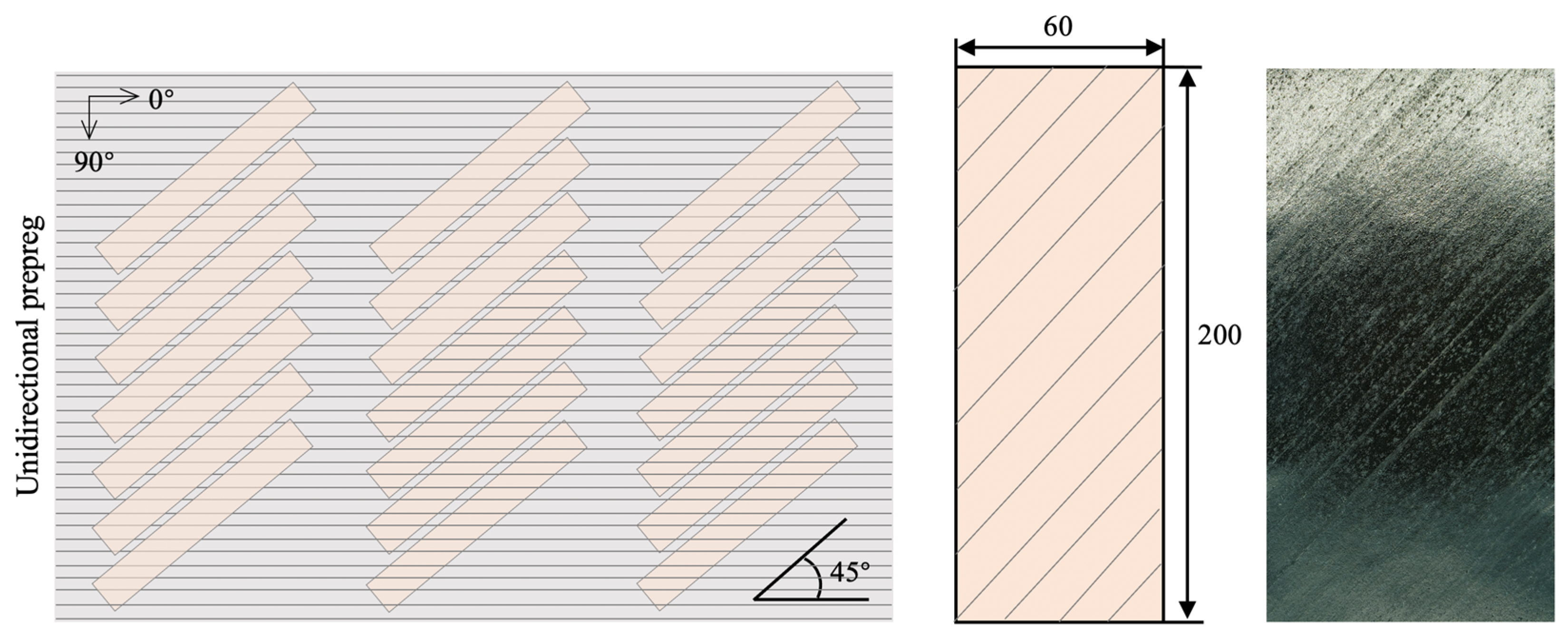
2.2. In-Plane Shear Testing of Prepreg

Sample preparation: The layering arrangement for the in-plane shear performance testing specimens of the prepreg was [45/−45/45/−45]. After layering, the specimens were placed in a vacuum bag and pre-pressed at 1 bar pressure. Subsequently, as shown in Figure 2a, the specimens were marked with lines using a 45° angle method and characterized into four zones (A, B, C, and D), with the identified feature points H1, H2, W1, and W2. The backsides of the specimens were marked with white marker lines along the fiber direction so that changes in the fiber angle during the tensile process could be recognized. The angle change of the 45° line passing through point W1 or W2 is often used for quantitatively evaluating the extent of the in-plane interlaminar shear behavior in prepreg. This angle change value is referred to as the shear angle (γ), and its relationship with the displacement (d) near the upper-grip end point (H1) is expressed by Formula (1):
  γ = π 2 2 arccos 2 2 + d 2 H W
where γ is the shear angle of the prepreg in zone A (i.e., the angle between the direction of the fiber deformation and the initial fiber direction); d is the displacement at point H1 or the beam displacement, which is the length of the specimen being stretched; H is the initial length of the specimen; and W is the initial width of the specimen.
In-plane shear test: We used the ±45° off-axis tensile test to characterize the macroscale in-plane shear behaviors of uncured UD prepreg specimens. During the off-axis tensile testing of the samples, a fixture consisting of two upper and two lower plates (Figure 2b) was first secured on a universal testing machine (ETM204C, Shenzhen WANCE Testing Equipment Co., Ltd., Shenzhen, China). The effective test gauge length of the test specimen was adjusted to 120 mm, ensuring that specimens within the same group had identical clamping forces. Next, thermocouples for temperature collection were installed on the off-axis tensile fixture near the ends of the prepreg, specifically at points H1 and H2. The environmental chamber (model FPYD-41AJW) was then used to provide four different test temperatures for the specimen: 30 °C, 80 °C, 120 °C, and 150 °C. After maintaining thermal equilibrium for 15 min and ensuring that the temperature difference between the two thermocouples was less than 1 °C (Figure 2c), the tensile test was initiated. The test was stopped when the tensile distance reached 35 mm. Simultaneously, the in-plane interlaminar shear behavior of the prepreg was compared under four different stretching rates: 1 mm/min, 2 mm/min, 10 mm/min, and 100 mm/min. Each group consisted of three repeated tests. Throughout the tensile testing process, a DIC system (FETECH 3200, Shenzhen Fetech Technology Co., Ltd., Shenzhen, China) was employed to capture the deformation data of the standard specimen feature points in the width (V), length (U), and thickness (W) directions, producing two-dimensional strain maps.
Figure 3 illustrates the concepts of the in-plane shear and interlaminar shear in a ±45° off-axis tensile specimen of UD tape at both the macroscale and mesoscale. For a single unidirectional (UD) prepreg ply, constrained by the unidirectional orientation of the fibers, when subjected to off-axis tensile stress, it only generates shear forces in a single direction and lacks the ability to generate the theoretically defined “in-plane shear force couple” that can be observed in fabric forms. However, in practical composite simulations or manufacturing evaluations, it is essential to assess the in-plane shear performance of UD prepreg to evaluate its shear resistance capability. Therefore, to determine this parameter, it is often necessary to design off-axis tensile specimens with ±45° layups (as per international testing standard ASTM D3518), in which the different fiber orientations in the upper and lower layers produce distinct responses to the off-axis tension, thereby inducing interlaminar shear behaviors through the effects of friction and resin shear lag, which, in turn, cause in-plane shear deformation in the single-layer prepreg. In conclusion, in UD prepregs, the in-plane shear behavior is essentially a macroscale concept rather than a strictly mesoscale one. In this study, we focus on the in-plane shear behavior at the macroscale.

2.3. Rheological Behavior Testing of Prepreg

Unlike unidirectional non-crimped dry-fiber fabrics in off-axis tensile tests, composite material prepregs contain resin. Changes in the resin viscosity and flow properties induced by temperatures or resin curing during testing can affect the shear behavior of prepregs, consequently influencing changes in the shear angles [42]. Therefore, accurately testing the variation in the prepreg viscosity with temperature and time is crucial for a precise quantitative analysis of the prepreg shear behavior.
Viscosity testing of prepregs was conducted using a rotational rheometer (TA DHR-2). Samples, in the form of small circular discs with diameters of 25 mm, were layered and pre-pressed in the same stacking sequence, [45/−45/45/−45], as in the in-plane shear testing. The samples were then placed between the upper and lower rotors of the rheometer, with the material’s bottom adhered to the lower rotor using polyimide adhesive tape to prevent slipping during testing [43,44]. (a) For the viscosity–temperature relationship test, the strain was set to 0.1%, the frequency was set to 1 Hz, and a normal force of 5 N was applied after reaching the set temperature of 30 °C. After allowing the instrument ambient temperature to reach the designated temperature and maintaining it for 5 min to ensure thorough temperature equilibration in all regions of the material, the test was initiated with a heating rate of 3 °C/min. The test was stopped when the temperature reached 180 °C, obtaining the viscosity–temperature curve for the prepreg. (b) For the viscosity–time relationship test, the testing temperature was set to 150 °C, and the scanning time was 1800 s. The frequency and pressure conditions were consistent with the settings mentioned above.

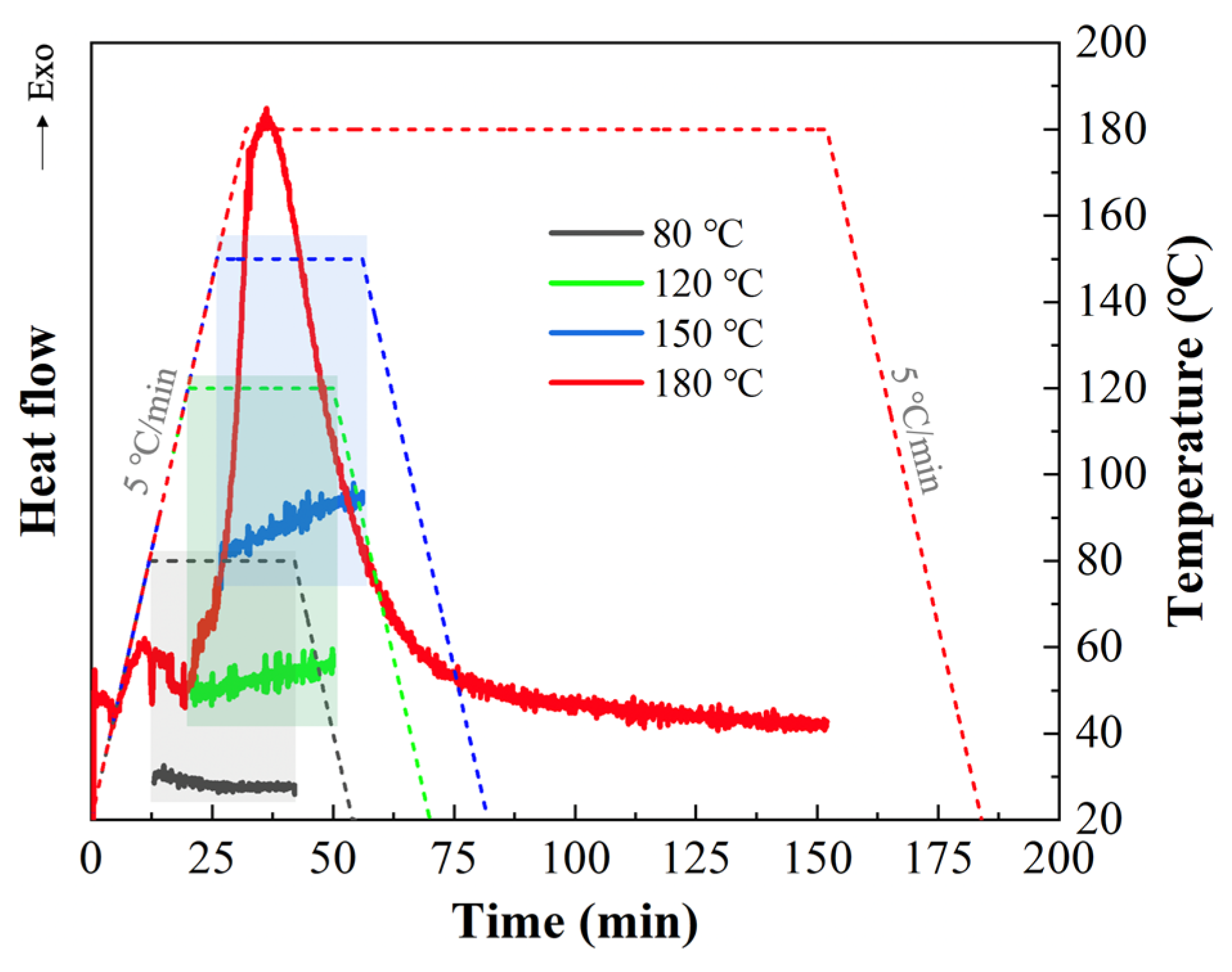
2.4. Curing Kinetics

The curing kinetics of the prepreg under the same time as that of the in-plane shear test process were analyzed by differential scanning calorimetry (DSC) (Netzsch, DSC 214, Selb, Germany), which was used to analyze the relationships between the curing degree, viscosity, and shear behaviors. Specifically, a 10 mg prepreg sample was weighed and placed into a crucible, followed by heating from 20 °C to 80 °C, 120 °C, and 150 °C at a rate of 5 °C/min. After being held for 30 min, corresponding to the shear preheating time and shear testing time, it was then cooled to 20 °C at a rate of 5 °C/min. For comparison, the complete cured curve was also tested according to the curing process provided by the prepreg supplier (i.e., curing at 180 °C for 2 h, with the other parameters set the same as mentioned above).

3. Results and Discussion

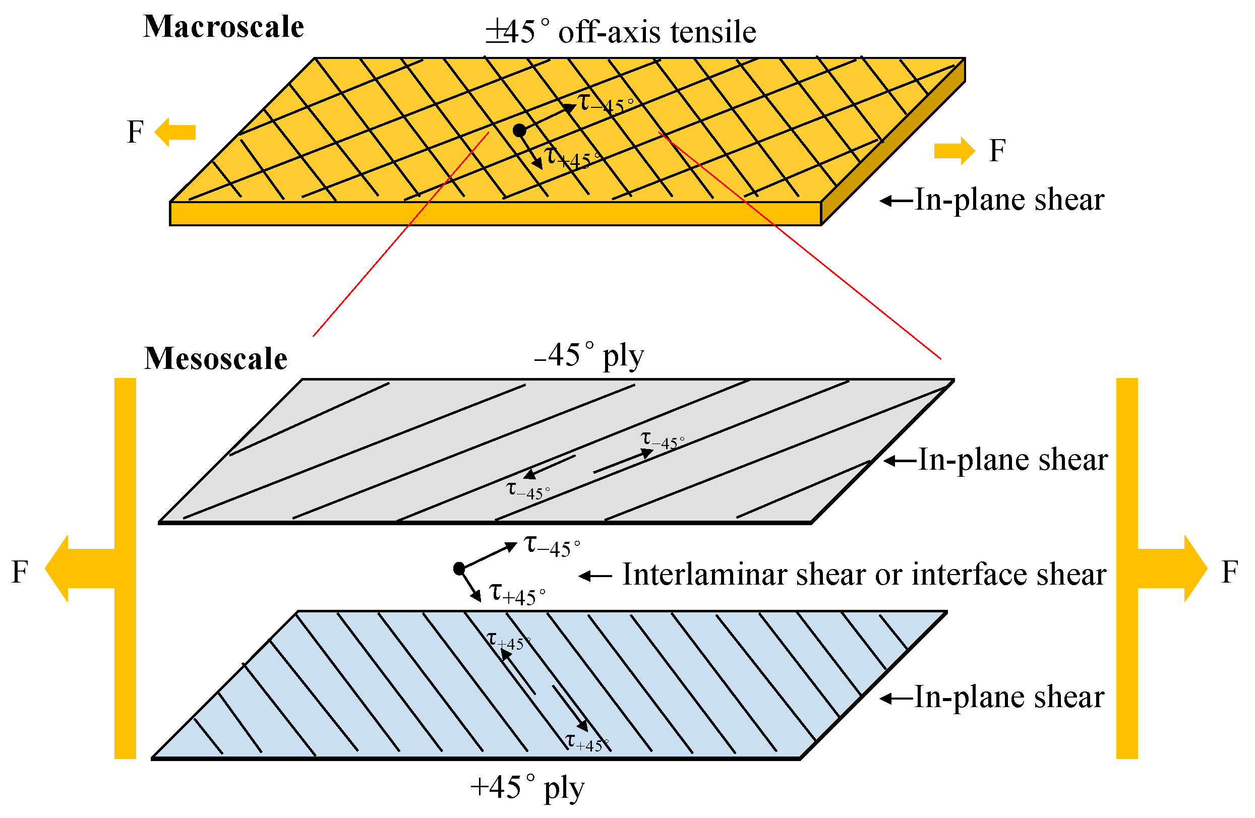
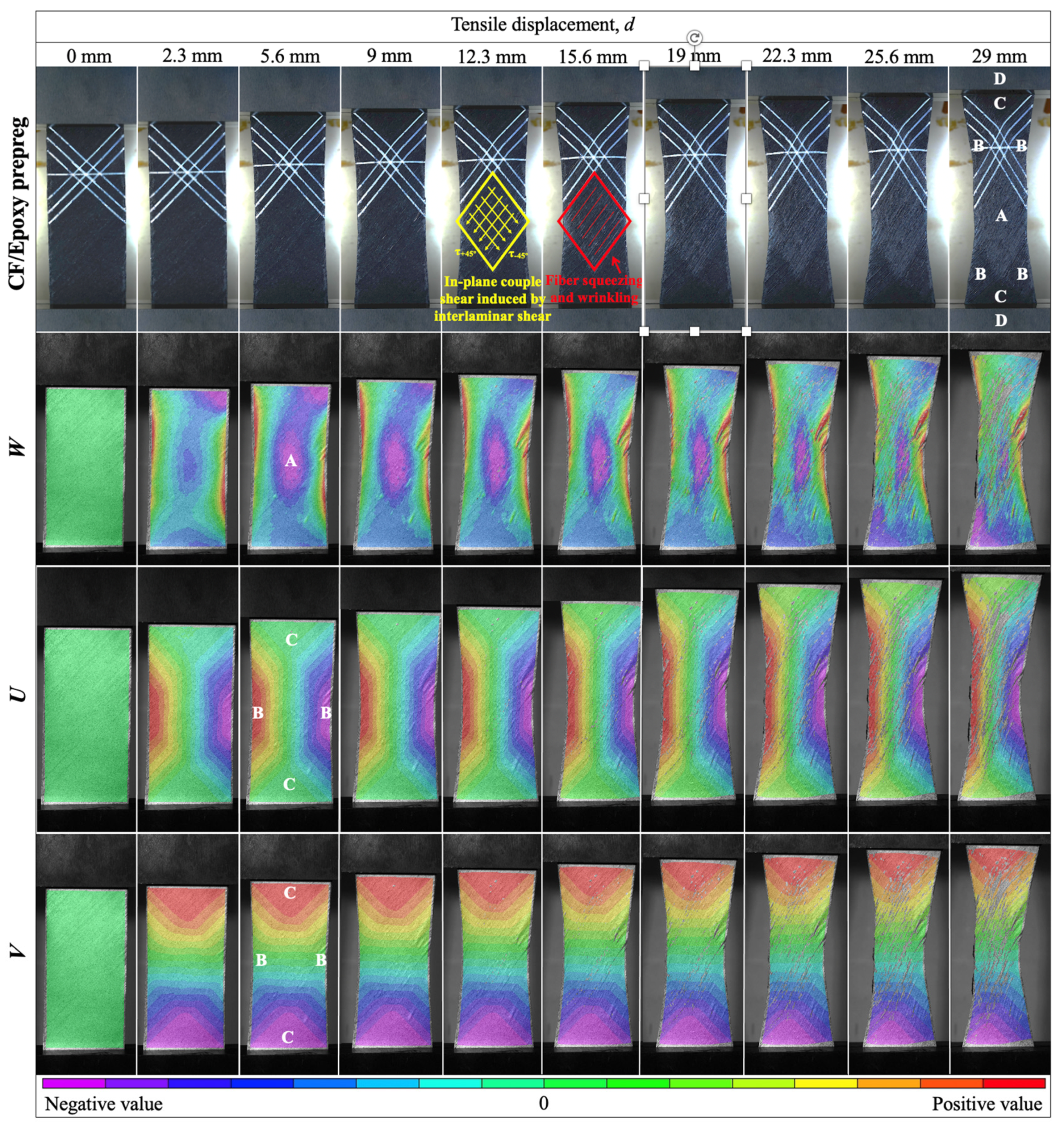
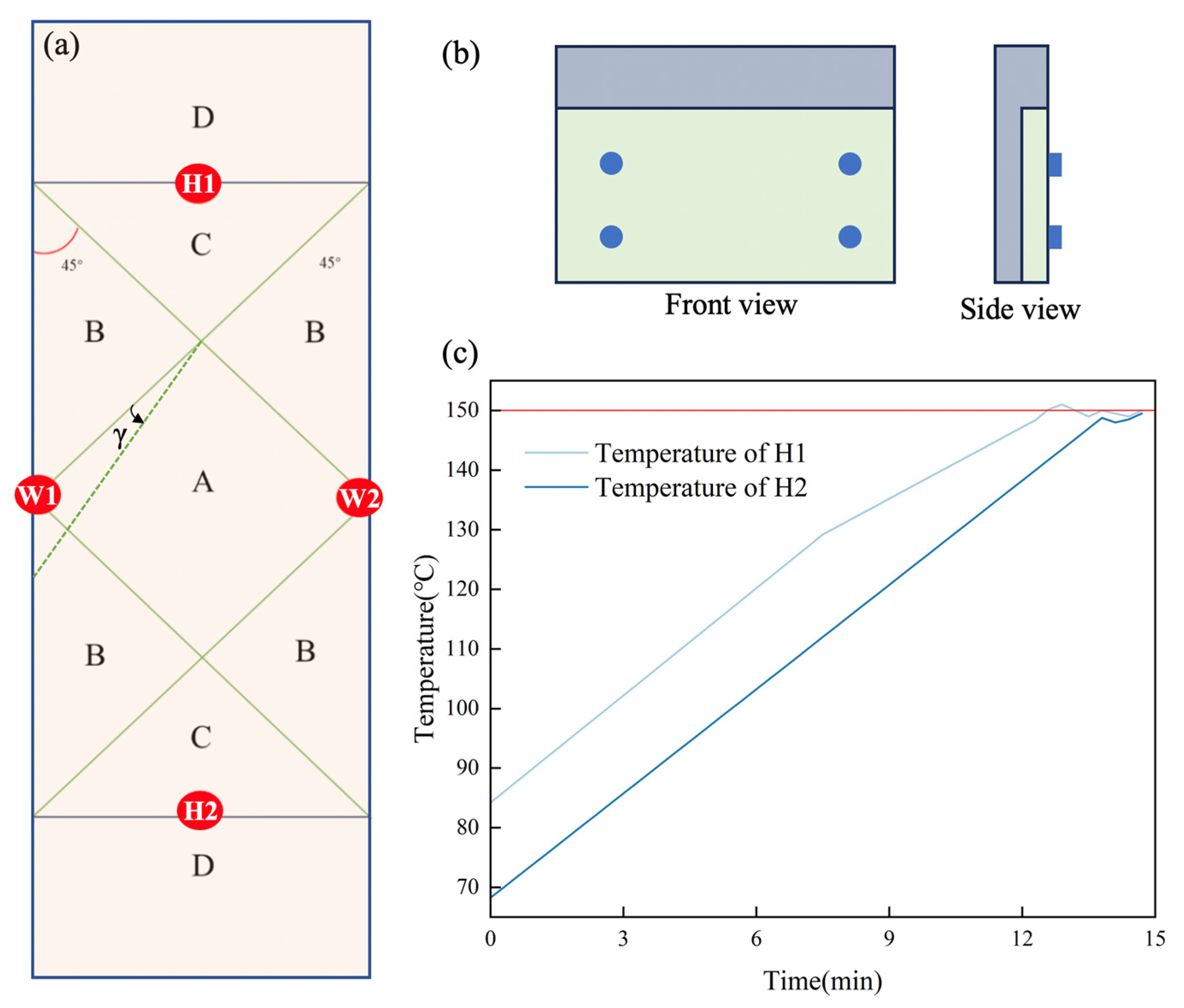
3.1. In-Plane Shear Characteristic Zones

The tensile in-plane shear behavior of the uncured CF/epoxy prepreg with a ±45° layup is illustrated in Figure 4. With increasing displacement, the prepreg gradually elongates in the length direction, while uneven contraction occurs in the width direction. At high tensile displacements, noticeable fiber squeezing and wrinkles start to appear (red lines), accompanied by distinct dark and light zones on the specimen surface, corresponding precisely to the A, B, and C zones in Figure 2a. The deformation data (purple area) in the W direction distinctly reveal the evolution of zone A, transitioning from no initial shear behavior to gradually increasing shear behavior at d = 5.6 mm, which eventually disappears at d > 29 mm. The U-directional DIC map identifies symmetrical contraction in the two B zones, persisting until the end, while zone C shows no significant deformation in the width direction, maintaining a constant area. The V-directional map indicates that zone B undergoes no apparent deformation in the length direction, while the deformation in zone C is induced by tensile displacement, with no significant change in the area observed.
Thus, under the tensile constraints imposed by the clamps at both ends, the in-plane shear deformation of the prepreg can be divided into four characteristic zones with the following features: zone A is the completely sheared zone; zone B is the semi-sheared deformation zone; zone C is the zone influenced by the clamp constraints, experiencing no shear deformation; zone D is the clamped zone, experiencing no shear deformation.
According to the definitions provided above and Figure 3 and Figure 4, when the off-axis tensile displacement (d) is less than 15.6 mm, the ±45° specimens primarily exhibit macroscale in-plane shear behavior (yellow lines in Figure 4), induced by the interlaminar interface shear between the +45° ply and −45° ply at the mesoscale (Figure 3). However, when d > 15.6 mm, fiber squeezing and wrinkling began to occur (red lines in Figure 4), induced by the interlaminar interface shear between the +45° ply and −45° ply at the mesoscale, as well as by the in-plane shear between parallel fiber yarns squeezing at the mesoscale. When d > 29 mm, the in-plane shear disappears in the completely sheared zone (A), as indicated by the purple strain variation along the W direction in Figure 4.

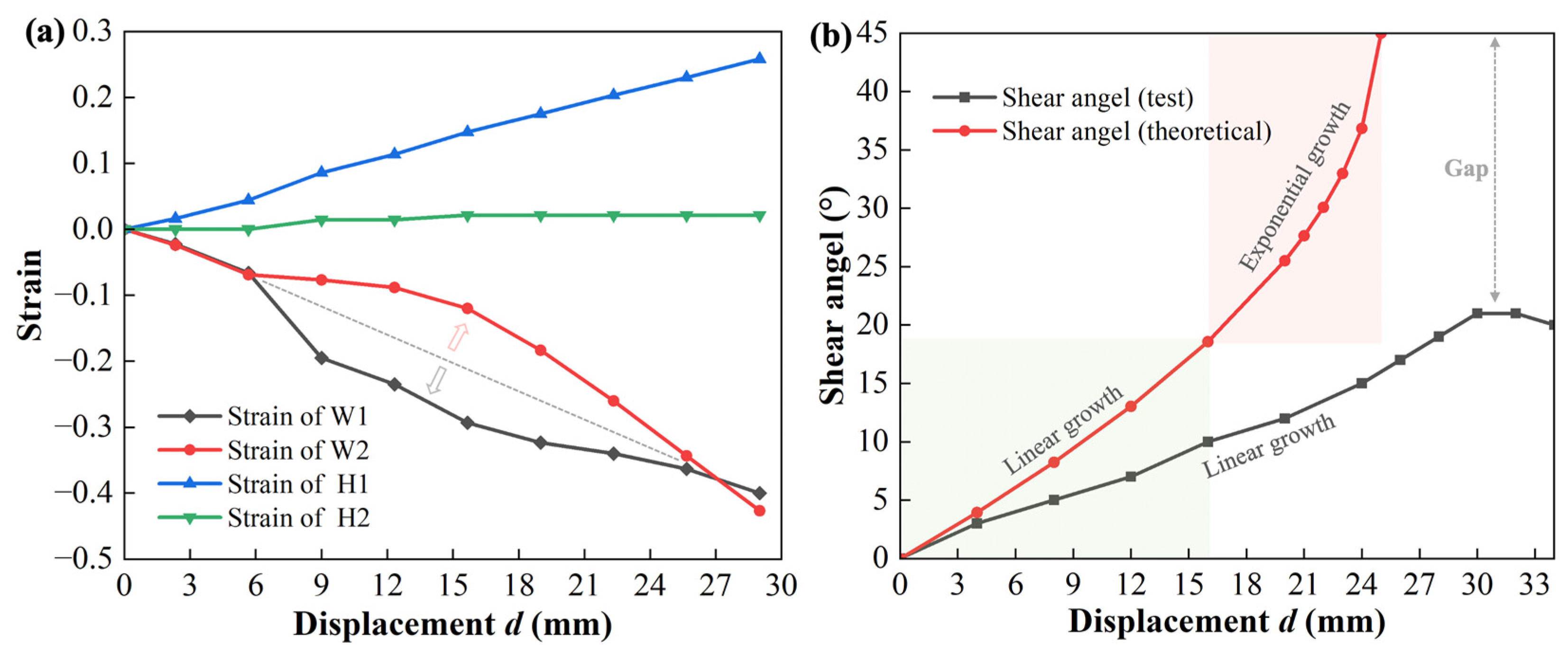
3.2. Quantitative Analysis of In-Plane Shear

The displacement changes of the four characteristic points, H1, H2, W1, and W2, during the tensile process are depicted in Figure 5a. It can be observed that the strain at point H1 linearly increases with the elongation of the prepreg during tensile loading. In contrast, the strain at H2 remains consistently zero due to the fixed constraints of the lower clamp, directly confirming that zone C experienced no shear deformation. However, the strain trends at points W1 and W2 are similar, with a temporary opposite deviation midway, indicating asymmetric shear deformation on both sides of the prepreg in zone B, caused by the non-uniform shear deformation in zone A, as seen in Figure 4. Theoretically, the complete shearing of the yarns in zone A induces the slipping of the yarns in zone B, while the yarns in zone C hold and fix the yarns in zone B. The combined effect of the yarns in zones A and C on zone B leads to the occurrence of semi-shear deformation in zone B. However, in reality, due to the difficulty of achieving an ideal uniformly distributed state of yarns at the microscopic scale during the manufacturing process, the deformation of the yarns in zone A is uneven in experiments. This unevenness results in the asymmetry of the deformation in zone B on both sides. Moreover, this asymmetrical difference gradually increases as the tensile loading progresses, as observed at d = 29 mm in Figure 4.
For the relationship between the shear angle (γ) and tensile displacement (d), combined with Equation 1 and Figure 5b, we can deduce through theoretical calculations that, under the assumption that the fibers can freely rotate, as the tensile displacement gradually increases from d = 0 mm to d = 24 mm, the shear angle changes from 0° to 45°, indicating that the fibers are tending toward a vertical distribution. Specifically, when the d is less than 15.6 mm, the increase in the in-plane shear angle of the prepreg approaches linearity. This is because, at small angles, the shear deformation is primarily controlled by the rotation of the fibers. However, as the angle continues to increase, the fibers start to squeeze each other, reducing the gap, and wrinkles begin to form, increasing the impact on the fiber shear deformation. This is consistent with the red-marked diamond frame in Figure 4 that shows that, during the tensile process, when d > 12.3 mm, the fibers in the shear region (A) begin to squeeze each other. When d = 15.6 mm, the compression of the fibers gradually becomes severe, resulting in the appearance of obvious wrinkles. At this point, the shear angle increases rapidly at an exponential rate until d = 24 mm, when the shear angle reaches 45°. However, in actual shear tests on prepreg with a [45/−45/45/−45] layup, the fiber rotation is constrained by both the in-plane and out-of-plane resin, as well as by the compression of the in-plane fibers and the obstruction from the out-of-plane perpendicular fibers. This results in the actual maximum rotated shear angle of the fibers (black line in Figure 5b) being far from the theoretical 45°. Instead, it maintains a relatively slow linear increase and reaches a plateau when d > 29 mm, with no further increase. Further increasing the displacement causes mutual compression between the fibers, leading to the onset of significant inter-ply sliding or wrinkling. This is consistent with the experimental observation in Figure 4, in which the purple region representing the shear behavior in the A zone gradually disappears after d > 29 mm, and significant wrinkles appear in zone B.

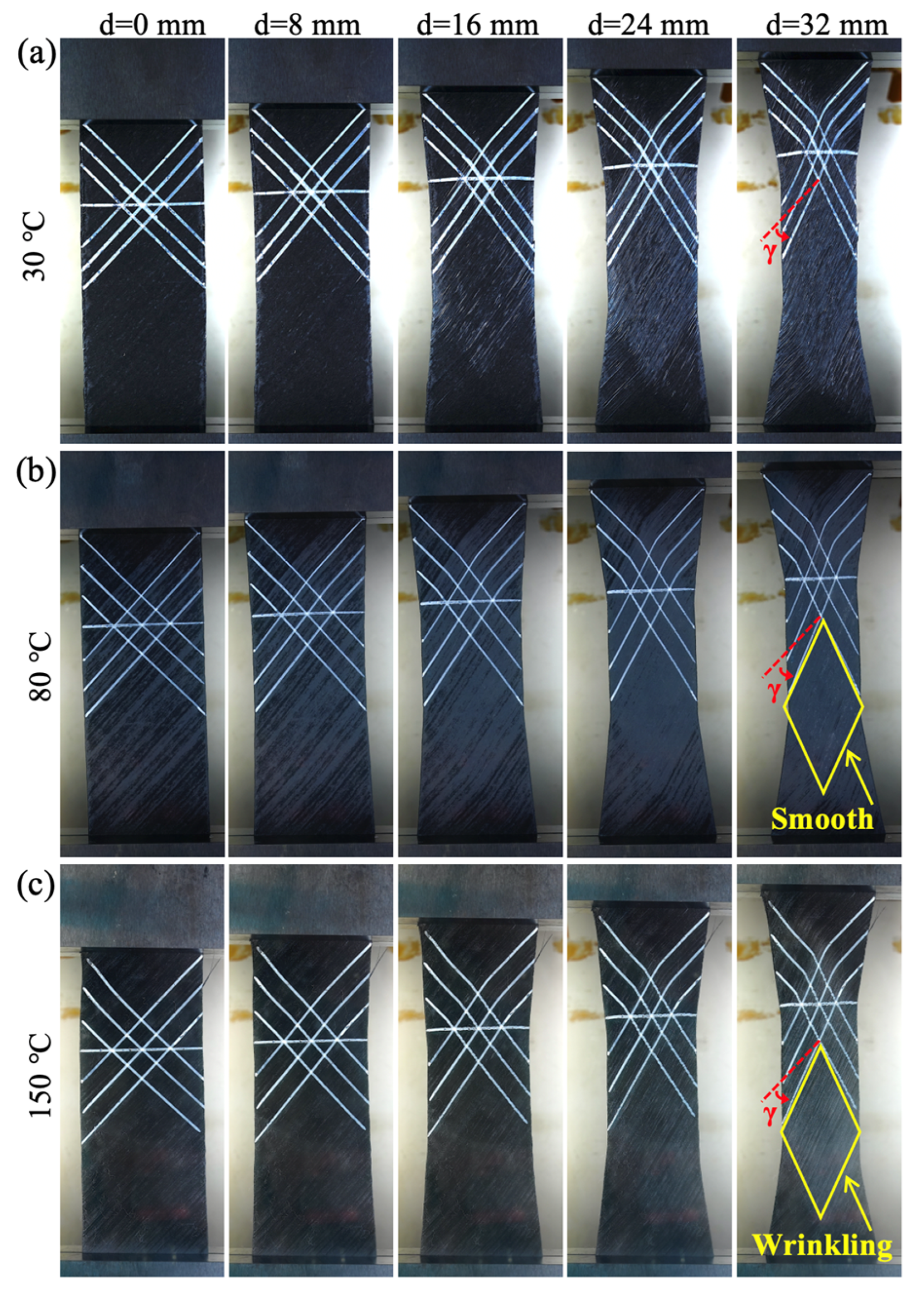
3.3. Temperature Influence

The molding temperature is a crucial factor affecting the resin flow, curing rate, deformability of the prepreg, and quality of the composite components during the molding process of thermoset composites [45]. Digital images of the in-plane shear testing at different temperatures are shown in Figure 6, and the corresponding force resistances to the in-plane shear deformations are collected in Figure 7a. With the increase in the test environment temperature, a noticeable change in the specimen appearance is observed, accompanied by a significant decrease in the shear deformation force resistance. At 30 °C, the force resistance to the in-plane shear deformation is significantly higher than those at other temperatures. The lowest shear force resistance is observed at 120 °C and 150 °C, where the curves almost overlap. The main reason for the observed changes in the appearance and force resistance is the variation in the resin viscosity caused by the temperature increase. At this time, two competing behaviors affecting the change in viscosity occur: temperature increase promotes molecular movement, which helps to reduce the viscosity, and it promotes epoxy curing, increasing the viscosity. This is evidenced by Figure 7b,c and Figure 8. As shown in Figure 7b, the viscosity–temperature curve of the prepreg indicates a rapid decrease in viscosity with the temperature increase from 30 °C to 150 °C, with the viscosity at 120 °C being similar to that at 150 °C. This is consistent with the trend of the almost overlapped force resistance to the in-plane shear deformation with the temperature change. However, the viscosity starts to increase after the temperature exceeds 150 °C due to the occurrence of curing. Further insights from the viscosity–time curve in Figure 7c also reveal that under in-plane shear tensile testing conditions at 150 °C for nearly 30 min, the viscosity approximately doubles from 9721 Pa·s to 17,116 Pa·s due to the resin curing. However, even with this increase, the viscosity remains significantly lower than that of 32,305 Pa·s at 80 °C (i.e., the magnitude of the viscosity increase due to curing is much lower than the magnitude of the viscosity reduction caused by the temperature rise). Therefore, it can be concluded that the decrease in the resin viscosity caused by the temperature is a direct factor influencing the in-plane shear force behavior of the prepreg within 30 min.
However, it is worth noting that, although the temperature increase is beneficial in reducing the resin viscosity and shear force, there is no significant difference in the shear angles (Figure 7d). Instead, the shear angle values at the higher temperature of 150 °C are slightly lower than those at 80 °C. This is mainly because after slight curing at 150 °C, although the increase in viscosity has little effect on the tensile force of the sample, it has a significant impact on the movement of the fibers in the local shear area (A). At this point, the movement of the fibers is hindered by the shear resistance from the fibers and cured resins in the in-plane and out-of-plane perpendicular directions, resulting in a decrease in the shear angle, but producing more pronounced mutual squeezing and wrinkling (Figure 6b,c).
The evidence for the increase in viscosity and curing degree at different temperatures during shear testing is revealed in Figure 8. It can be seen that, under the curing temperature of 180 °C (red curve) recommended by the supplier, the CF/epoxy sample started to release heat during the heating stage, and it completed the entire curing process approximately 40 min after reaching 180 °C. In contrast, during the entire testing time, including heating to 80 °C, 120 °C, and 150 °C, and maintaining these temperatures for 30 min, no complete curing exothermic peaks were observed. However, through subtle observation and comparison of the slope of the heat flow curve, it can still be observed that the slopes increase with the increasing temperature, indicating the occurrence of slight curing, and the curing rate increases with the increasing temperature. However, within our limited testing time, corresponding to the time scale of in-plane shear testing, the overall degree of curing remains at a relatively low level. The above phenomenon well explains why the viscosity starts to increase after the temperature exceeds 150 °C in Figure 7b,c, and why the shear angle at 150 °C in Figure 7d is lower than that at 80 °C.
In summary, in the actual manufacturing process of composite materials, appropriately raising the temperature of the CF/epoxy prepreg can effectively reduce the molding resistance, decrease the frictional resistance and wear between the mold and fibers, improve the molding efficiency, and enhance the product quality without significantly affecting the predetermined orientation of the fibers.

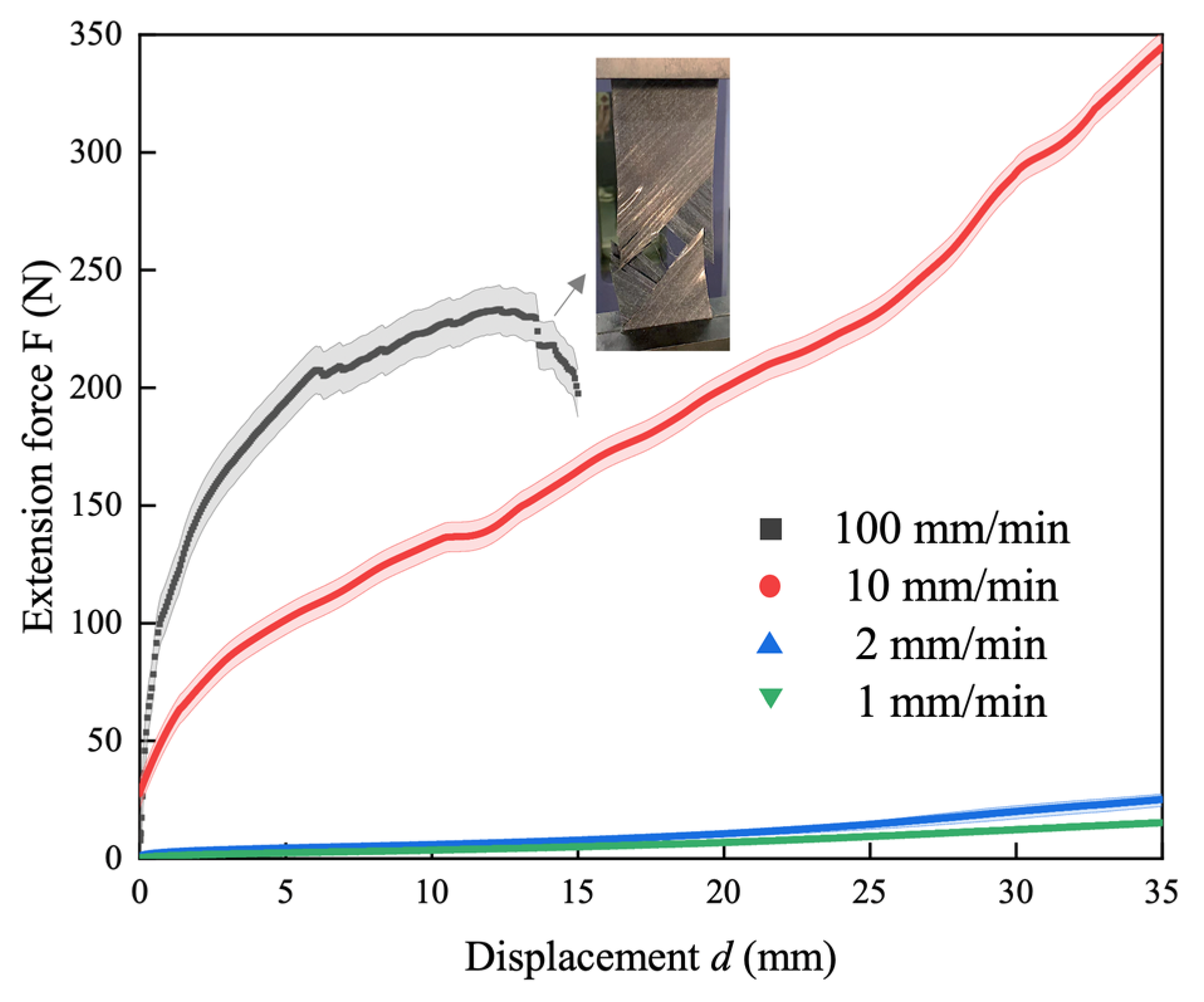
3.4. Shear Rate Influence

Figure 9 illustrates the influence of the tensile rate on the in-plane shear behavior of the prepreg. It is evident that the shear deformation resistance force of the prepreg is positively correlated with the tensile rate. Higher tensile rates result in greater shear deformation resistance. Notably, at a rate of 100 mm/min, the prepreg experiences direct tensile failure around d = 15 mm. This corresponds to the rapid increase in the mid-shear angle and resistance force, as shown in Figure 5b and Figure 7a. This is primarily attributed to the substantial viscous resistance of the resin at room temperature, wherein its high relaxation time hinders the epoxy resin from responding promptly under a high tensile rate, consequently leading to the in-plane shear failure of the prepreg. Therefore, in practical manufacturing processes of composite materials, it is essential to choose an appropriate laying rate to enhance the molding quality or elevate the temperature of the CF/epoxy prepreg to reduce the resin viscosity and improve the shear response speed, thereby achieving the enhanced manufacturing efficiency of the preform.

4. Conclusions

Based on the shear deformation and wrinkling issues faced by unidirectional thermoset prepregs in the AFP process of preform manufacturing, this study, including the ±45° off-axis tension determination, DIC triaxial strain characterization, and shear angle prediction, establishes a quantitative characterization method for in-plane shear issues in prepregs. It successfully reveals four shear characteristic zones and conducts dynamic quantitative evaluations of the deformation in the thickness, width, and length dimensions, as well as of the shear angles. The results indicate that the actual shear angle is significantly lower than the theoretical shear angle due to the constraints imposed by the fibers from both the in-plane and out-of-plane directions. When the off-axis tensile displacement (d) is less than 15.6 mm, the ±45° specimens primarily exhibit macroscale in-plane shear behavior, induced by interlaminar interface shear between the +45° ply and −45° ply at the mesoscale. The shear angle increases linearly with the d. However, when d > 15.6 mm, fiber squeezing and wrinkling begin to occur. When d > 29 mm, the completely sheared behavior in the A zone gradually disappears, and further increases in the shear displacement lead to mutual fiber squeezing, resulting in significant interlayer slip or wrinkling. The resin viscosity is a direct factor influencing the in-plane shear resistance of CF/epoxy prepreg, but it has no obvious effect on the shear angle. The impact of the resin viscosity increase induced by the curing on the shear deformation is much smaller than that of the temperature-induced viscosity reduction. At higher shear rates, the in-plane deformation resistance of the prepreg increases, leading to interlayer cracking failure. Therefore, during the manufacturing process of CF/epoxy preform, it is necessary to appropriately increase the temperature to simultaneously improve the forming efficiency and preform quality. These findings provide a theoretical reference for quantitatively analyzing the in-plane shear deformation capability and for predicting defects in composite processing, highlighting the ±45° UD prepreg layups in AFP manufacturing.

Author Contributions

Conceptualization, H.Z. and G.Y.; methodology, H.L. and H.Z.; software, H.L. and H.Z.; validation, G.Y., H.Z., and B.G.; formal analysis, H.L. and G.Y.; investigation, H.L. and H.Z.; resources, G.Y. and Y.W.; data curation, H.L. and G.Y.; writing—original draft preparation, H.L. and H.Z.; writing—review and editing, H.L. and Y.W.; visualization, H.L., G.Y., and B.G.; supervision, G.Y. and Y.W.; project administration, G.Y.; funding acquisition, G.Y. All authors have read and agreed to the published version of the manuscript.

Funding

This research was funded by the National Key R&D Program of China, grant number 2022YFB3704503.

Data Availability Statement

Data are contained within the article.

Conflicts of Interest

The authors declare no conflicts of interest.

References

  1. Van Barschot, J. Airbus en Boeing vliegen met TenCate. NRC Handelsblad, Rotterdam, 5 January 2005; Volume 17. [Google Scholar]
  2. Rodríguez-García, V.; Gómez, J.; Cristiano, F.; Gude, M.R. Industrial manufacturing and characterization of multiscale CFRP laminates made from prepregs containing graphene-related materials. Mater. Res. Express 2020, 7, 075601. [Google Scholar] [CrossRef]
  3. Zhang, S.; Tang, H.; Tang, D.; Liu, T.; Liao, W. Effect of fabrication process on the microstructure and mechanical performance of carbon fiber reinforced PEEK composites via selective laser sintering. Compos. Sci. Technol. 2024, 246, 110396. [Google Scholar] [CrossRef]
  4. Frossard, G.; Cugnoni, J.; Gmür, T.; Botsis, J. Ply thickness dependence of the intralaminar fracture in thin-ply carbon-epoxy laminates. Compos. Part A-Appl. Sci. 2018, 109, 95–104. [Google Scholar] [CrossRef]
  5. Dirk, H.J.L.; Ward, C.; Potter, K.D. The engineering aspects of automated prepreg layup: History, present and future. Compos. Part B-Eng. 2012, 43, 997–1009. [Google Scholar]
  6. Poursatip, A. Transitioning composites manufacturing simulation into industrial practice: Challenges and opportunities. In Proceedings of the ICMAC 2015-International Conference on Manufacturing Advanced Composites, Bristol, UK, 24–25 June 2015. [Google Scholar]
  7. Harrison, P.; Abdiwi, F.; Guo, Z.; Potluri, P.; Yu, W. Characterising the shear–tension coupling and wrinkling behaviour of woven engineering fabrics. Compos. Part A-Appl. Sci. 2012, 43, 903–914. [Google Scholar] [CrossRef]
  8. Potter, K. Bias extension measurements on cross-plied unidirectional prepreg. Compos. Part A-Appl. Sci. 2002, 33, 63–73. [Google Scholar] [CrossRef]
  9. Boisse, P.; Hamila, N.; Guzman-Maldonado, E.; Madeo, A.; Hivet, G.; Dell’Isola, F. The bias-extension test for the analysis of in-plane shear properties of textile composite reinforcements and prepregs: A review. Int. J. Mater. Form. 2017, 10, 473–492. [Google Scholar] [CrossRef]
  10. Harrison, P.; Clifford, M.J.; Long, A. Shear characterisation of viscous woven textile composites: A comparison between picture frame and bias extension experiments. Compos. Sci. Technol. 2004, 64, 1453–1465. [Google Scholar] [CrossRef]
  11. McGuinness, G.; ÓBrádaigh, C. Characterisation of thermoplastic composite melts in rhombus-shear: The picture-frame experiment. Compos. Part A-Appl. Sci. 1998, 29, 115–132. [Google Scholar] [CrossRef]
  12. Trejo, E.A.; Ghazimoradi, M.; Butcher, C.; Montesano, J. Assessing strain fields in unbalanced unidirectional non-crimp fabrics. Compos. Part A-Appl. Sci. 2020, 130, 105758. [Google Scholar] [CrossRef]
  13. Haanappel, S.; ten Thije, R.H.; Sachs, U.; Rietman, B.; Akkerman, R. Formability analyses of uni-directional and textile reinforced thermoplastics. Compos. Part A-Appl. Sci. 2014, 56, 80–92. [Google Scholar] [CrossRef]
  14. Li, H.; Wei, Y.; Wang, L. A general model for predicting the off-axis performance of fiber reinforced composite materials. In Structures; Elsevier: Amsterdam, The Netherlands, 2021; Volume 34, pp. 2087–2097. [Google Scholar]
  15. Zhu, B.; Yu, T.; Tao, X. An experimental study of in-plane large shear deformation of woven fabric composite. Compos. Sci. Technol. 2007, 67, 252–261. [Google Scholar] [CrossRef]
  16. Hautefeuille, A.; Comas-Cardona, S.; Binetruy, C. Mechanical signature and full-field measurement of flow-induced large in-plane deformation of fibrous reinforcements in composite processing. Compos. Part A-Appl. Sci. 2019, 118, 213–222. [Google Scholar] [CrossRef]
  17. Mei, M.; Huang, J.; Yu, S.; Zeng, T.; He, Y.; Wei, K. Shear deformation characterization and normalized method of tricot-stitched unidirectional non-crimp fabric. Compos. Sci. Technol. 2024, 246, 110391. [Google Scholar] [CrossRef]
  18. Schirmaier, F.J.; Dörr, D.; Henning, F.; Kärger, L. A macroscopic approach to simulate the forming behaviour of stitched unidirectional non-crimp fabrics (UD-NCF). Compos. Part A-Appl. Sci. 2017, 102, 322–335. [Google Scholar] [CrossRef]
  19. Boisse, P.; Hamila, N.; Madeo, A. The difficulties in modeling the mechanical behavior of textile composite reinforcements with standard continuum mechanics of Cauchy. Some possible remedies. Int. J. Solids Struct. 2018, 154, 55–65. [Google Scholar] [CrossRef]
  20. Harrison, P.; Alvarez, M.F.; Anderson, D. Towards comprehensive characterisation and modelling of the forming and wrinkling mechanics of engineering fabrics. Int. J. Solids Struct. 2018, 154, 2–18. [Google Scholar] [CrossRef]
  21. Wang, Y.; Chea, M.K.; Belnoue, J.P.-H.; Kratz, J.; Ivanov, D.S.; Hallett, S.R. Experimental characterisation of the in-plane shear behaviour of UD thermoset prepregs under processing conditions. Compos. Part A-Appl. Sci. 2020, 133, 105865. [Google Scholar] [CrossRef]
  22. Scobbo, J., Jr.; Nakajima, N. Modification of the mechanical energy resolver for high temperature and rigid material applications. Polym. Test. 1990, 9, 245–255. [Google Scholar] [CrossRef]
  23. Stanley, W.; Mallon, P. Intraply shear characterisation of a fibre reinforced thermoplastic composite. Compos. Part A-Appl. Sci. 2006, 37, 939–948. [Google Scholar] [CrossRef]
  24. Larberg, Y.R.; Åkermo, M.; Norrby, M. On the in-plane deformability of cross-plied unidirectional prepreg. J. Compos. Mater. 2012, 46, 929–939. [Google Scholar] [CrossRef]
  25. Larberg, Y.; Åkermo, M. In-plane deformation of multi-layered unidirectional thermoset prepreg–modelling and experimental verification. Compos. Part A-Appl. Sci. 2014, 56, 203–212. [Google Scholar] [CrossRef]
  26. Groves, D.; Bellamy, A.; Stocks, D. Anisotropic rheology of continuous fibre thermoplastic composites. Composites 1992, 23, 75–80. [Google Scholar] [CrossRef]
  27. Groves, D. A characterization of shear flow in continuous fibre thermoplastic laminates. Composites 1989, 20, 28–32. [Google Scholar] [CrossRef]
  28. Hörmann, P.M. Thermoset Automated Fibre Placement–on Steering Effects and Their Prediction. Ph.D. Thesis, Technische Universität München, München, Germany, 2015. [Google Scholar]
  29. Haanappel, S.; Akkerman, R. Shear characterisation of uni-directional fibre reinforced thermoplastic melts by means of torsion. Compos. Part A-Appl. Sci. 2014, 56, 8–26. [Google Scholar] [CrossRef]
  30. Dörr, D.; Henning, F.; Kärger, L. Nonlinear hyperviscoelastic modelling of intra-ply deformation behaviour in finite element forming simulation of continuously fibre-reinforced thermoplastics. Compos. Part A-Appl. Sci. 2018, 109, 585–596. [Google Scholar] [CrossRef]
  31. Gao, M.; Wang, C.; Yang, D.; Fu, Y.; Li, B.; Guan, R. Effect of stress concentration and deformation temperature on the tensile property and damage behavior of a B4Cp/Al composite. J. Mater. Res. Technol. 2021, 15, 2601–2610. [Google Scholar] [CrossRef]
  32. Aghdam, M.; Morsali, S.; Hosseini, S.; Sadighi, M. Mechanical behavior of unidirectional SiC/Ti composites subjected to off-axis loading at elevated temperatures. Mater. Sci. Eng. A 2017, 688, 244–249. [Google Scholar] [CrossRef]
  33. Zhai, Z.; Jiang, B.; Drummer, D. Temperature-dependent response of quasi-unidirectional E-glass fabric reinforced polypropylene composites under off-axis tensile loading. Compos. Part B-Eng. 2018, 148, 180–187. [Google Scholar] [CrossRef]
  34. Shah, S.; Megat-Yusoff, P.; Sharif, T.; Hussain, S.Z.; Choudhry, R. Off-axis tensile performance of notched resin-infused thermoplastic 3D fibre-reinforced composites. Mech. Mater. 2022, 175, 104478. [Google Scholar] [CrossRef]
  35. Yao, L.; Chuai, M.; Li, H.; Chen, X.; Quan, D.; Alderliesten, R.; Beyens, M. Temperature effects on fatigue delamination behavior in thermoset composite laminates. Eng. Fract. Mech. 2024, 295, 109799. [Google Scholar] [CrossRef]
  36. Zhang, B.; Kim, B.C. Experimental characterisation of large in-plane shear behaviour of unidirectional carbon fibre/epoxy prepreg tapes for continuous tow shearing (CTS) process. Compos. Part A-Appl. Sci. 2022, 162, 107168. [Google Scholar] [CrossRef]
  37. Pheysey, J.; De Cola, F.; Pellegrino, A.; Martinez-Hergueta, F. Strain rate and temperature dependence of short/unidirectional carbon fibre PEEK hybrid composites. Compos. Part B-Eng. 2024, 268, 111080. [Google Scholar] [CrossRef]
  38. Rashidi, A.; Montazerian, H.; Yesilcimen, K.; Milani, A. Experimental characterization of the inter-ply shear behavior of dry and prepreg woven fabrics: Significance of mixed lubrication mode during thermoset composites processing. Compos. Part A-Appl. Sci. 2020, 129, 105725. [Google Scholar] [CrossRef]
  39. Jiang, L.; Wang, J.; Xiao, S.; Li, Y.; Yang, L. Dynamic tensile properties of carbon/glass hybrid fibre composites under intermediate strain rates via DIC and SEM technology. Thin-Walled Struct. 2023, 190, 110986. [Google Scholar] [CrossRef]
  40. Hsu, F.Y.; Hung, K.C.; Xu, J.W.; Liu, J.W.; Wu, Y.H.; Chang, W.S.; Wu, J.H. Analyzing the impact of veneer layup direction and heat treatment on plywood strain distribution during bending load by digital image correlation (DIC) technique. J. Mater. Res. Technol. 2023, 27, 5257–5265. [Google Scholar] [CrossRef]
  41. Liu, Z.; Mu, T.; Lan, X.; Liu, L.; Bian, W.; Liu, Y.; Leng, J. Damage behavior analysis of unidirectional fiber reinforced shape memory polymer composites. Compos. Struct. 2023, 304, 116392. [Google Scholar] [CrossRef]
  42. Gu, Q.; Quan, Z.; Shen, M.; Xie, Y.; Yu, J. Fabrication and braiding angle effect on the improved interlaminar shear performances of 3D braided sandwich hybrid composites. J. Mater. Res. Technol. 2023, 25, 5795–5806. [Google Scholar] [CrossRef]
  43. Robles, J.B.; Dubé, M.; Hubert, P.; Yousefpour, A. Healing study of poly (ether-imide) and poly ether ether ketone using resin films and a parallel plate rheometer. Compos. Part A-Appl. Sci. 2023, 174, 107736. [Google Scholar] [CrossRef]
  44. Das, A.; Choong, G.Y.; Dillard, D.A.; De Focatiis, D.S.; Bortner, M.J. Characterizing friction for fiber reinforced composites manufacturing: Method development and effect of process parameters. Compos. Part B-Eng. 2022, 236, 109777. [Google Scholar] [CrossRef]
  45. Obande, W.; O’Rourke, K.; Stankovic, D.; Lykkeberg, A.; Garden, J.A.; Brádaigh, C.Ó.; Ray, D. Multi-stage, in-situ polymerisation for low-exotherm, liquid resin infusion of thick thermoplastic laminates at room temperature. Compos. Commun. 2024, 45, 101788. [Google Scholar] [CrossRef]
Figure 1. Unidirectional CF/epoxy prepreg used for in-plane interlaminar shear performance testing.
Jcs 08 00133 g001
Figure 2. In-plane shear testing of unidirectional CF/epoxy prepreg: (a) concept of four shear characteristic zones and shear angle (γ); (b) fixture configuration; and (c) representative temperature collection curves of thermocouples at points H1 and H2, where the red line represents 150 °C.
Jcs 08 00133 g002
Figure 3. Diagram of in-plane shear and interlaminar shear in ±45° off-axis tensile specimen of UD tape at both the macroscale and mesoscale.
Jcs 08 00133 g003
Figure 4. The ±45°off-axis tensile testing process and DIC strain maps of CF/epoxy prepreg depicting in-plane shear deformations in the thickness (W), width (U), and length (V) directions.
Jcs 08 00133 g004
Figure 5. (a) Strain–displacement curves of characteristic points H1, H2, W1, and W2 during in-plane shear testing process; (b) variation in theoretical and actual shear angles in zone A of the prepreg with tensile displacement.
Jcs 08 00133 g005
Figure 6. Digital images of in-plane shear testing of the CF/epoxy prepreg at different temperatures: (a) 30 °C, (b) 80 °C, and (c) 150 °C.
Jcs 08 00133 g006
Figure 7. Impact of temperature on in-plane shear behaviors of the CF/epoxy prepreg: (a) deformation resistance forces of the prepreg; (b) viscosity–temperature curve of the prepreg; (c) viscosity–time curve of the prepreg at 150 °C; (d) variations in shear angles in specimens at different temperatures.
Jcs 08 00133 g007
Figure 8. The curing kinetic curves of the prepreg analyzed by DSC. Note: For the incomplete-curing DSC curves at 80 °C, 120 °C, and 150 °C, due to significant temperature fluctuations in the transient states from heating to constant temperature and from constant temperature to cooling, which affect the analysis of the curing behavior during the constant-temperature stage, we have omitted the curve data for the heating and cooling processes here.
Jcs 08 00133 g008
Figure 9. Impact of shear rate on in-plane shear behavior of CF/epoxy prepregs.
Jcs 08 00133 g009
Disclaimer/Publisher’s Note: The statements, opinions and data contained in all publications are solely those of the individual author(s) and contributor(s) and not of MDPI and/or the editor(s). MDPI and/or the editor(s) disclaim responsibility for any injury to people or property resulting from any ideas, methods, instructions or products referred to in the content.

