
Punching Shear of FRP-RC Slab–Column Connections: A Comprehensive Database


Abstract
1. Introduction
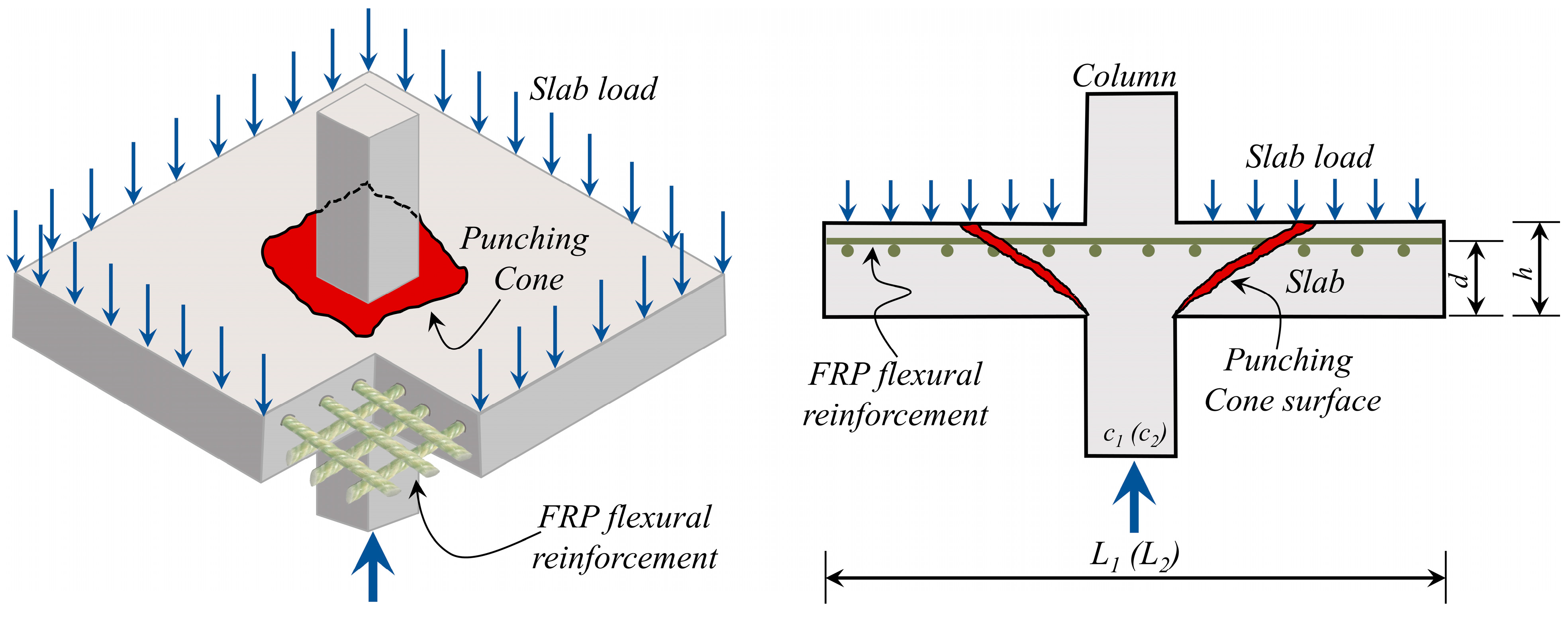
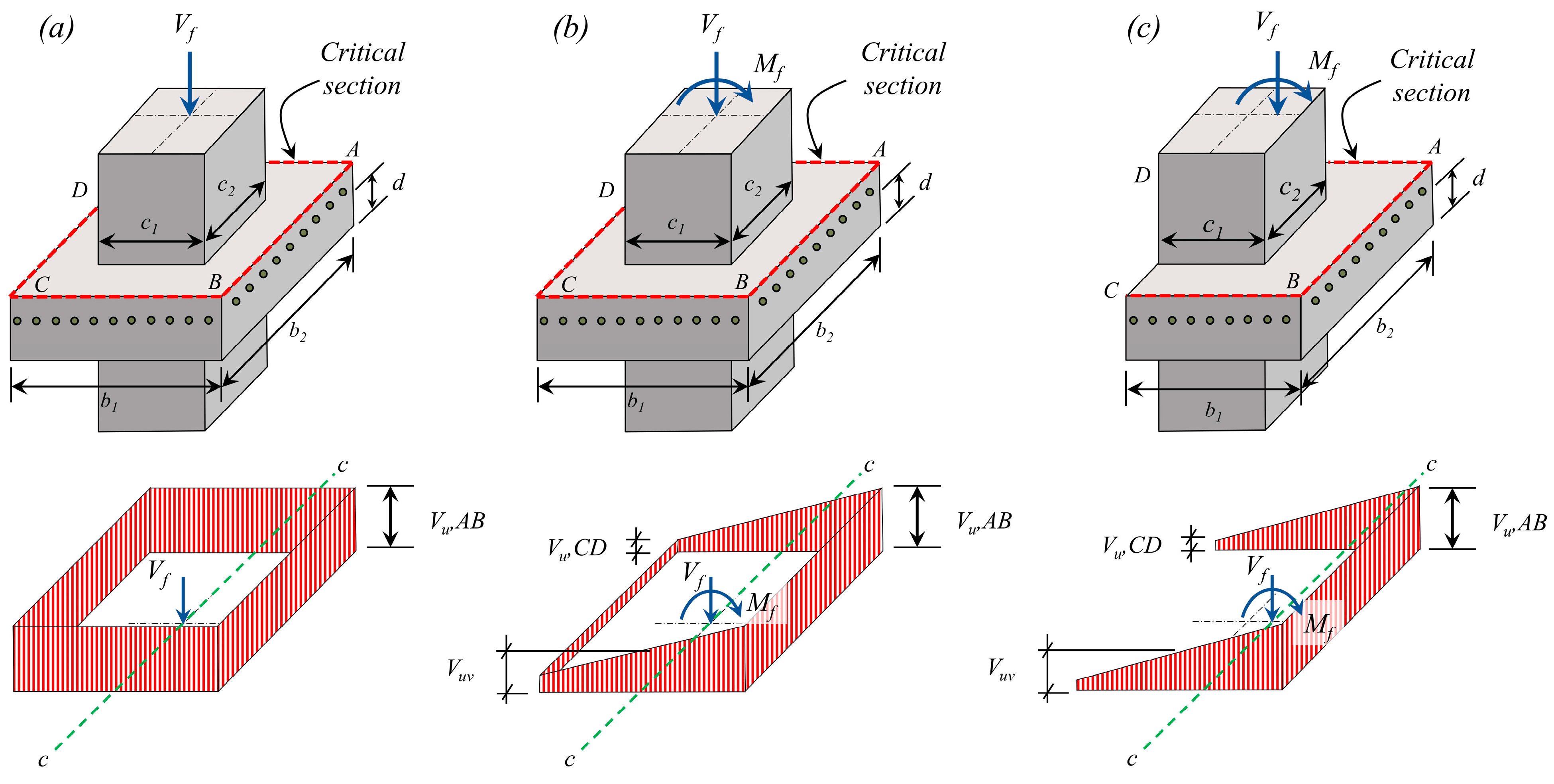
2. Concentric and Eccentric Punching Shear Behavior
3. Code Provisions
3.1. Punching Shear Model Adopted in ACI 440.11-22
3.2. Punching Shear Model Adopted in CSA/S806-12
3.3. Punching Shear Model Adopted in JSCE (2007)
4. Punching Shear Database
5. Assessment of Design Provisions
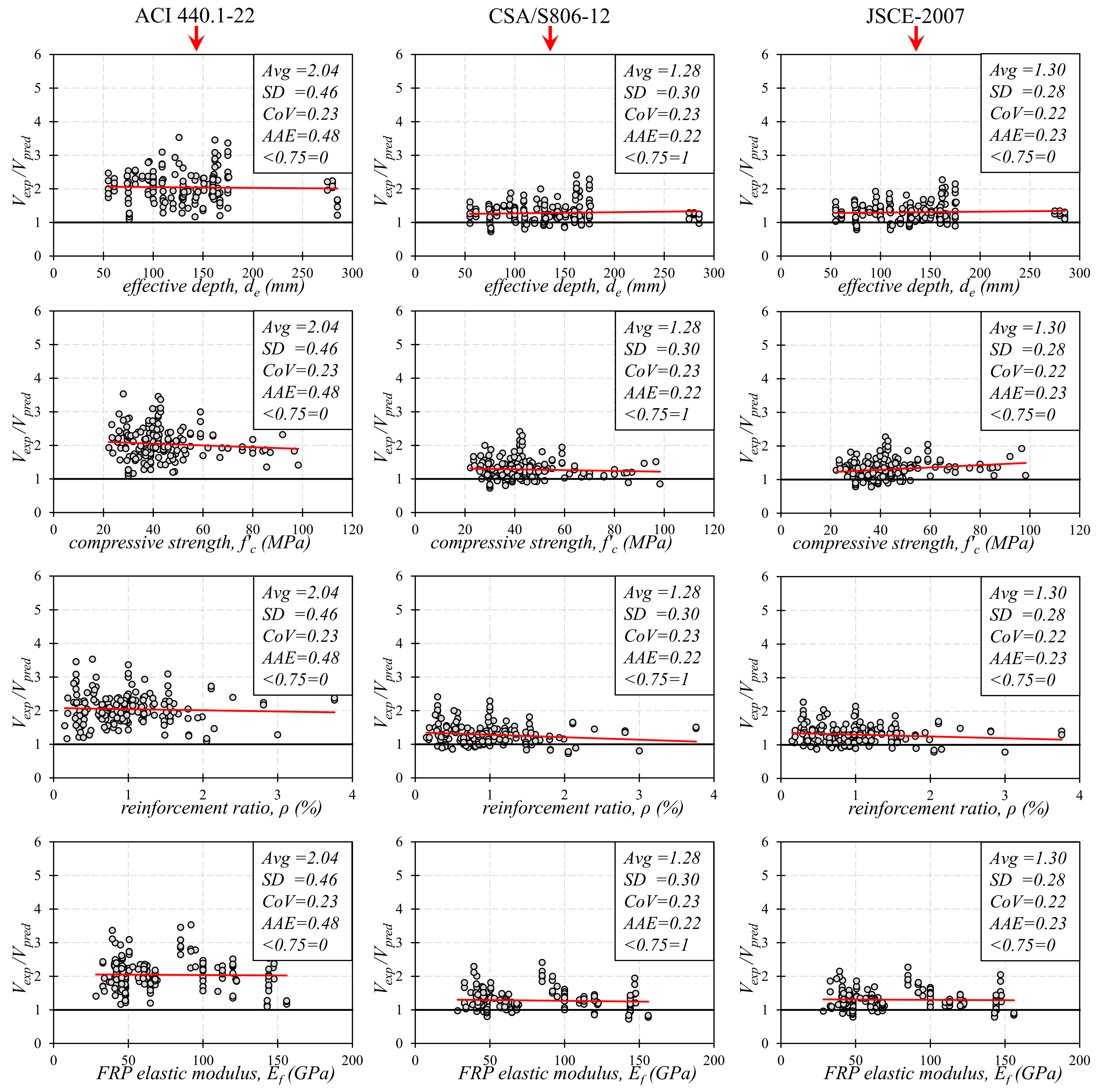
5.1. Assessment of Design Models for Connections without Shear Reinforcement
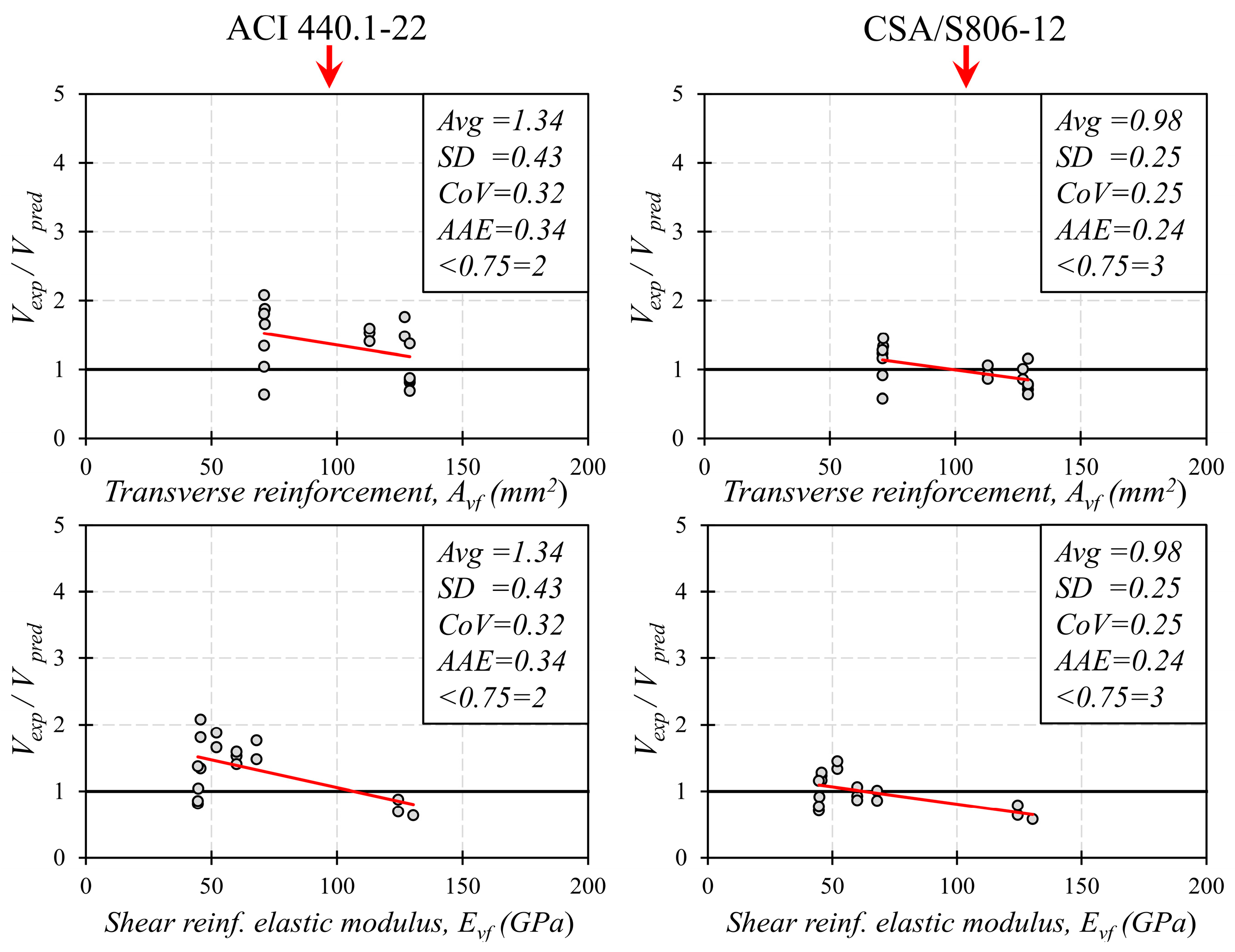
5.2. Assessment of Design Models for Connections with Shear Reinforcement
6. Summary and Conclusions
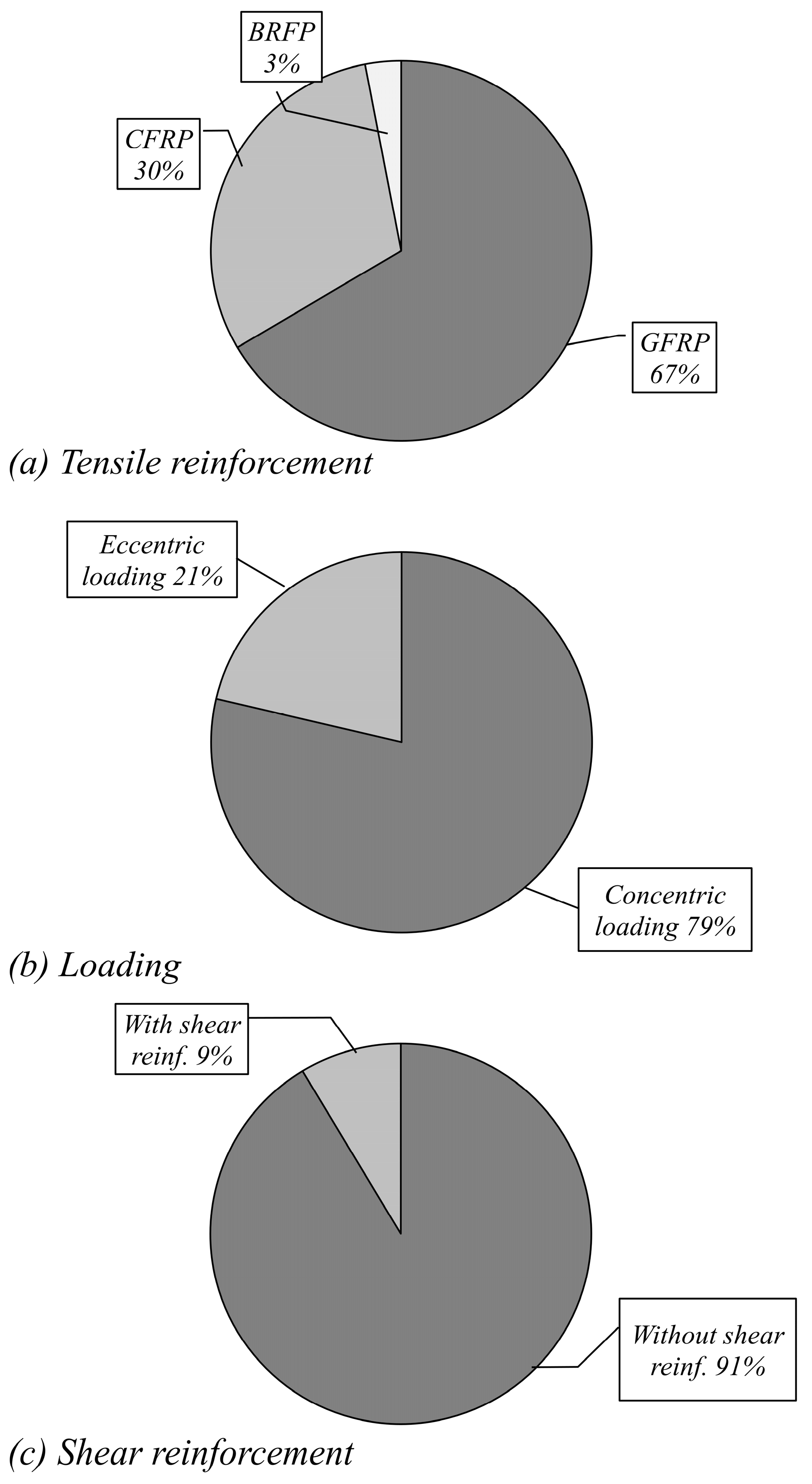
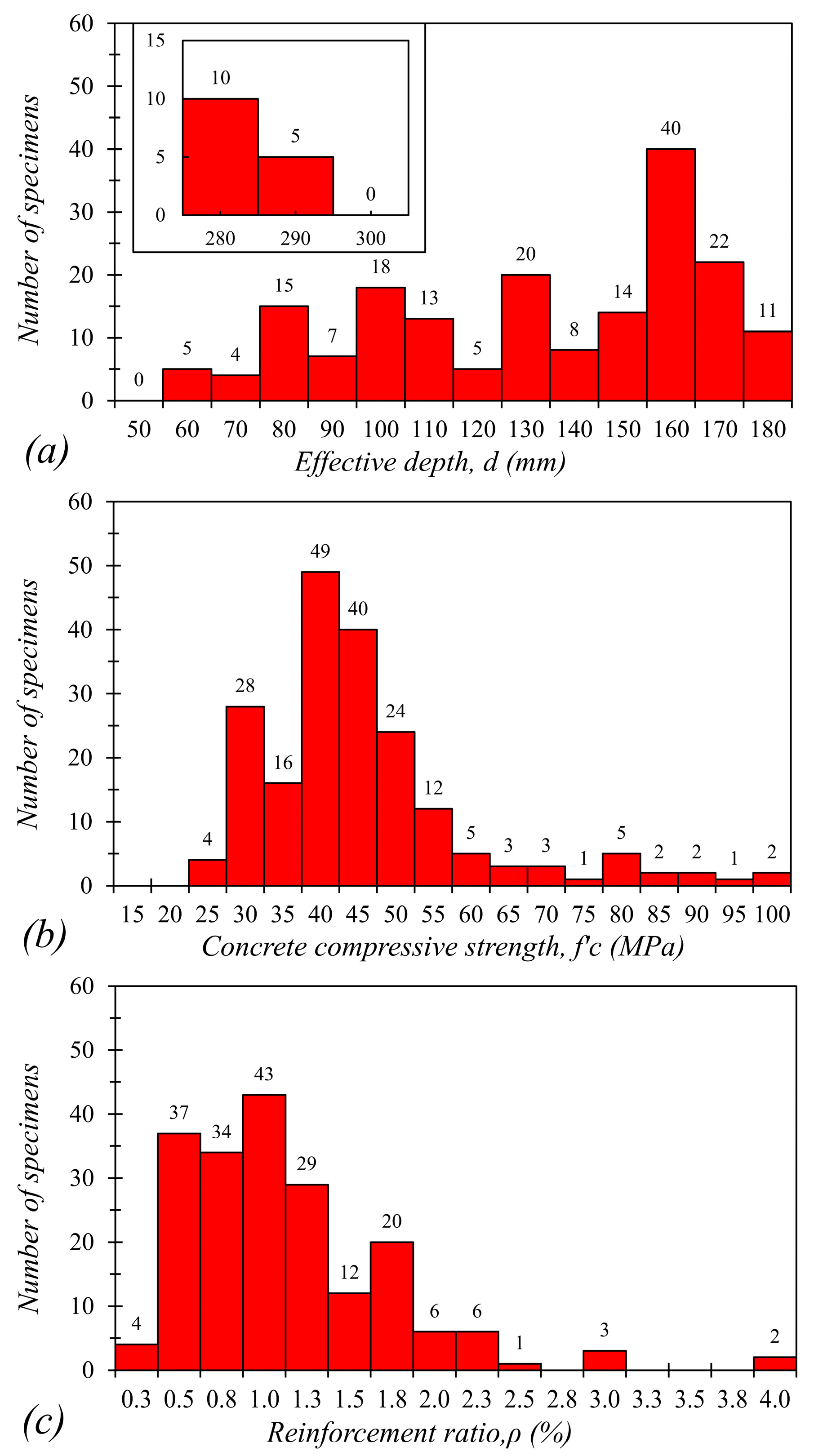
- The surveyed worldwide database comprised 197 punching shear tests for FRP-RC column–slab connections. In the database, 67% of the specimens were reinforced with GFRP, followed by CFRP (30%) and BFRP (3%). The percentage of specimens subject to an unbalanced moment (eccentric loading) was 21% compared to 79% of the specimens subjected to concentric loading. Moreover, less than 10% of the specimens were reinforced with FRP shear reinforcement. The database covered a wide range of material and cross-sectional properties.
- For connections without shear reinforcement, the ACI 440.11-12 model resulted in the highest conservatism among the models, with an Avg. of 2.04 compared to 1.28 and 1.3 for the CSA/S806-12 and the JSCE-2007 models, respectively. The high conservatism of the ACI 440 model is due to the assumption that only the uncracked region of the slab contributes to the shear capacity. The high conservatism for the ACI 440.11-22 model resulted in a high SD and AAE, while the CSA/S806-12 and the JSCE-2007 models had similar measures. However, all models resulted in a similar CoV of 23%. All models resulted in a horizontal trendline with all variables indicating a consistent prediction accuracy across variables’ ranges.
- For connections with FRP shear reinforcement, the statistical measures indicate that the ACI 440.11-22 model resulted in conservative predictions with an Avg of 1.34 for the Vexp/Vpred ratios. The CSA/S806-12 model resulted in a slightly unconservative estimate with Avg of 0.98 for the Vexp/Vpred ratios. However, the ACI 440 resulted in higher variability, as indicated by the 32% CoV compared to 25% for the CSA/S806-12 model. On the other hand, the trendlines indicate downward trends with respect to the variables for both models.
- By examining the Vexp/Vpred ratios with respect to Evf, it can be noted that all specimens with Evf > 100 GPa resulted in Vexp/Vpred ratios less than 1.0. This indicates that the proposed procedures (Equations (10) and (11)) are not applicable for CFRP shear reinforcement. Further evaluation is required when additional experimental data is available.
- In future work, it is recommended that researchers focus on connections with FRP shear reinforcement in terms of experimental and analytical work due to the limited data available in this area.
Author Contributions
Funding
Data Availability Statement
Conflicts of Interest
Appendix A

| Specimen | Location | Type | L1 (mm) | L2 (mm) | C1 (mm) | C2 (mm) | d (mm) | (GPa) | ||||||
|---|---|---|---|---|---|---|---|---|---|---|---|---|---|---|
| ACI 440.1R-22 | CSA/S806-12 | JSCE (1997) | ||||||||||||
| El-Ghandour et al. (2003) [13] | ||||||||||||||
| SG1 | interior | GFRP | 2000 | 2000 | 200 | 200 | 142 | 32 | 45 | 0.18 | 170 | 1.16 | 1.13 | 1.06 |
| SC1 | interior | CFRP | 2000 | 2000 | 200 | 200 | 142 | 32.8 | 110 | 0.15 | 229 | 1.55 | 1.2 | 1.11 |
| SG2 | interior | GFRP | 2000 | 2000 | 200 | 200 | 142 | 46.4 | 45 | 0.38 | 271 | 1.54 | 1.25 | 1.24 |
| SG3 | interior | GFRP | 2000 | 2000 | 200 | 200 | 142 | 30.4 | 45 | 0.38 | 237 | 1.66 | 1.25 | 1.18 |
| SC2 | interior | CFRP | 2000 | 2000 | 200 | 200 | 142 | 29.6 | 110 | 0.35 | 317 | 2.2 | 1.29 | 1.22 |
| T. Hassan et al. (2000) [14] | ||||||||||||||
| 1 | Interior | CFRP | 1800 | 3000 | 575 | 225 | 165 | 59 | 147 | 0.57 | 1000 | 2.25 | 1.46 | 1.54 |
| 2 | Interior | CFRP | 1800 | 3000 | 575 | 225 | 165 | 59 | 147 | 0.57 | 1200 | 2.7 | 1.75 | 1.85 |
| 3 | Interior | CFRP | 1800 | 3000 | 575 | 225 | 165 | 59 | 147 | 0.57 | 1328 | 2.3 | 1.94 | 2.04 |
| Rahman et al. (2000) [15] | ||||||||||||||
| 1 | interior | CFRP | 2000 | 2500 | 250 | 150 | 162 | 42 | 85 | 0.3 | 622 | 3.08 | 2.15 | 2.02 |
| 2 | interior | CFRP | 2000 | 2500 | 250 | 150 | 162 | 42 | 85 | 0.3 | 698 | 3.46 | 2.41 | 2.27 |
| 3 | interior | CFRP | 2000 | 2500 | 250 | 150 | 162 | 42 | 85 | 0.3 | 575 | 2.85 | 1.99 | 1.87 |
| 4 | interior | CFRP | 2000 | 2500 | 250 | 150 | 162 | 42 | 85 | 0.3 | 534 | 2.64 | 1.84 | 1.74 |
| 5 | interior | CFRP | 2000 | 2500 | 250 | 150 | 162 | 42 | 85 | 0.3 | 584 | 2.89 | 2.02 | 1.9 |
| H.J. Louka (1999) [16] | ||||||||||||||
| 1 | interior | GFRP | 3000 | 1800 | 575 | 225 | 175 | 43 | 41.3 | 1 | 500 | 1.43 | 0.95 | 0.9 |
| 2 | interior | GFRP | 3000 | 1800 | 575 | 225 | 175 | 43 | 41.3 | 1 | 1050 | 2.99 | 2 | 1.88 |
| 3 | interior | GFRP | 3000 | 1800 | 575 | 225 | 175 | 43 | 41.3 | 1 | 875 | 2.5 | 1.67 | 1.57 |
| 4 | interior | GFRP | 3000 | 1800 | 575 | 225 | 175 | 43 | 39.3 | 1 | 1090 | 3.11 | 2.11 | 1.98 |
| 5 | interior | GFRP | 3000 | 1800 | 575 | 225 | 175 | 43 | 39.3 | 1 | 1180 | 3.37 | 2.29 | 2.15 |
| c1 | interior | CFRP | 3000 | 1800 | 575 | 225 | 175 | 55 | 100 | 1 | 1180 | 2.32 | 1.54 | 1.57 |
| c2 | interior | CFRP | 3000 | 1800 | 575 | 225 | 175 | 55 | 100 | 1 | 1000 | 1.97 | 1.31 | 1.33 |
| c3 | interior | CFRP | 3000 | 1800 | 575 | 225 | 175 | 55 | 100 | 1 | 1200 | 2.36 | 1.57 | 1.6 |
| K. Bouguerra et al. (2011) [17] | ||||||||||||||
| G-200-N | interior | GFRP | 3000 | 2500 | 600 | 250 | 165 | 49.1 | 44.5 | 1.2 | 732 | 2.02 | 1.23 | 1.27 |
| G-175-N | interior | GFRP | 3000 | 2500 | 600 | 250 | 143 | 35.2 | 41.6 | 1.2 | 484 | 1.82 | 1.12 | 1.06 |
| G-150-N | interior | GFRP | 3000 | 2500 | 600 | 250 | 118 | 35.2 | 41.6 | 1.2 | 362 | 1.73 | 1.06 | 1.04 |
| G-175-H | interior | GFRP | 3000 | 2500 | 600 | 250 | 143 | 46.8 | 41.6 | 1.2 | 704 | 2.38 | 1.48 | 1.53 |
| G-175-N-0.7 | interior | GFRP | 3000 | 2500 | 600 | 250 | 143 | 53.1 | 41.6 | 0.7 | 549 | 1.75 | 1.32 | 1.43 |
| G-175-N-0.35 | interior | GFRP | 3000 | 2500 | 600 | 250 | 143 | 35.1 | 41 | 0.35 | 506 | 1.98 | 1.77 | 1.68 |
| C-175-N | interior | CFRP | 3000 | 2500 | 600 | 250 | 145 | 40.3 | 122 | 0.4 | 530 | 1.9 | 1.16 | 1.14 |
| Dulude et al. (2013) [18] | ||||||||||||||
| G(0.7)30/20 | interior | GFRP | 2500 | 2500 | 300 | 300 | 130 | 34.3 | 48.2 | 0.71 | 329 | 1.89 | 1.16 | 1.16 |
| G(1.6)30/20 | interior | GFRP | 2500 | 2500 | 300 | 300 | 130 | 38.6 | 48.1 | 1.56 | 431 | 1.92 | 1.12 | 1.14 |
| G(0.7)45/20 | interior | GFRP | 2500 | 2500 | 450 | 450 | 135 | 44.9 | 48.2 | 0.71 | 400 | 1.42 | 0.91 | 1.03 |
| G(1.6)45/20 | interior | GFRP | 2500 | 2500 | 450 | 450 | 130 | 32.4 | 48.1 | 1.56 | 504 | 1.74 | 1.03 | 1.11 |
| G(0.3)30/35 | interior | GFRP | 2500 | 2500 | 300 | 300 | 285 | 34.3 | 48.2 | 0.34 | 825 | 1.64 | 1.24 | 1.19 |
| G(0.7)30/35 | interior | GFRP | 2500 | 2500 | 300 | 300 | 280 | 39.4 | 48.1 | 0.73 | 1071 | 2.04 | 1.23 | 1.2 |
| G(0.3)45/35 | interior | GFRP | 2500 | 2500 | 450 | 450 | 285 | 48.6 | 48.2 | 0.34 | 911 | 1.21 | 0.97 | 1.1 |
| G(0.7)45/35 | interior | GFRP | 2500 | 2500 | 450 | 450 | 280 | 29.6 | 48.1 | 0.73 | 1248 | 2.17 | 1.25 | 1.32 |
| Hassan et al. (2013b) [19] | ||||||||||||||
| G(0.7)30/20-B | interior | GFRP | 2500 | 2500 | 300 | 300 | 135 | 39 | 48.2 | 0.71 | 386 | 1.98 | 1.24 | 1.25 |
| G(1.6)30/20-B | interior | GFRP | 2500 | 2500 | 300 | 300 | 130 | 32 | 48.1 | 1.56 | 451 | 2.11 | 1.25 | 1.27 |
| G(1.6)45/20-B | interior | GFRP | 2500 | 2500 | 450 | 450 | 130 | 39 | 48.1 | 1.56 | 511 | 1.68 | 0.98 | 1.07 |
| G(0.3)30/35-B | interior | GFRP | 2500 | 2500 | 300 | 300 | 285 | 39 | 48.2 | 0.34 | 782 | 1.46 | 1.13 | 1.11 |
| G(0.7)30/35-B-1 | interior | GFRP | 2500 | 2500 | 300 | 300 | 280 | 30 | 48.1 | 0.73 | 1027 | 2.24 | 1.29 | 1.26 |
| G(0.7)30/35-B-2 | interior | GFRP | 2500 | 2500 | 300 | 300 | 280 | 47 | 48.1 | 0.73 | 1195 | 2.08 | 1.29 | 1.34 |
| G(0.3)45/35-B | interior | GFRP | 2500 | 2500 | 450 | 450 | 285 | 32 | 48.2 | 0.34 | 1020 | 1.68 | 1.25 | 1.3 |
| Matthys, S., and L. Taerwe. (2000) [6] | ||||||||||||||
| C1 | interior | CFRP | 1000 | 1000 | 133 * | 133 * | 96 | 30.4 | 91.8 | 0.27 | 181 | 2.81 | 1.87 | 1.76 |
| C1̕ | interior | CFRP | 1000 | 1000 | 203 * | 203 * | 96 | 30.4 | 91.8 | 0.27 | 189 | 2.25 | 1.5 | 1.51 |
| C2 | interior | CFRP | 1000 | 1000 | 133 * | 133 * | 95 | 29.6 | 95 | 1.05 | 255 | 2.78 | 1.7 | 1.61 |
| C2՛ | interior | CFRP | 1000 | 1000 | 203 * | 203 * | 95 | 29.6 | 95 | 1.05 | 273 | 2.28 | 1.39 | 1.41 |
| C3 | interior | CFRP | 1000 | 1000 | 133 * | 133 * | 126 | 28 | 92 | 0.52 | 347 | 3.53 | 2 | 1.81 |
| C3՛ | interior | CFRP | 1000 | 1000 | 203 * | 203 * | 126 | 28 | 92 | 0.52 | 343 | 2.75 | 1.56 | 1.52 |
| CS | interior | CFRP | 1000 | 1000 | 133 * | 133 * | 95 | 27 | 147.6 | 0.19 | 142 | 2.37 | 1.49 | 1.43 |
| CS՛ | interior | CFRP | 1000 | 1000 | 203 * | 203 * | 95 | 27 | 147.6 | 0.19 | 150 | 1.92 | 1.2 | 1.24 |
| H1 | interior | (C&G) | 1000 | 1000 | 133 * | 133 * | 95 | 96.7 | 37.3 | 0.62 | 207 | 1.83 | 1.51 | 1.92 |
| H2 | interior | (C&G) | 1000 | 1000 | 133 * | 133 * | 89 | 29.3 | 40.7 | 3.76 | 231 | 2.31 | 1.47 | 1.4 |
| H2՛ | interior | (C&G) | 1000 | 1000 | 71 * | 71 * | 89 | 29.3 | 40.7 | 3.76 | 171 | 2.38 | 1.51 | 1.3 |
| H3 | interior | (C&G) | 1000 | 1000 | 133 * | 133 * | 122 | 26.3 | 44.8 | 1.22 | 237 | 2.42 | 1.4 | 1.29 |
| H3՛ | interior | (C&G) | 1000 | 1000 | 71 * | 71 * | 122 | 26.3 | 44.8 | 1.22 | 217 | 2.93 | 1.69 | 1.41 |
| Joo-Ha Lee et al. (2009) [20] | ||||||||||||||
| GFU1 | interior | GFRP | 2300 | 2300 | 225 | 225 | 110 | 36.3 | 48.2 | 1.18 | 222 | 1.72 | 0.98 | 0.96 |
| GFB2 | interior | GFRP | 2300 | 2300 | 225 | 225 | 110 | 36.3 | 48.2 | 2.15 | 246 | 1.46 | 0.89 | 0.87 |
| GFB3 | interior | GFRP | 2300 | 2300 | 225 | 225 | 110 | 36.3 | 48.2 | 3 | 248 | 1.28 | 0.8 | 0.78 |
| Hemzah et al. (2019) [21] | ||||||||||||||
| C-F-S-10-4 | interior | CFRP | 600 | 600 | 88.6 * | 88.6 * | 75 | 51 | 144 | 0.3 | 103 | 2.21 | 1.34 | 1.33 |
| C-F-S-10-6 | interior | CFRP | 600 | 600 | 88.6 * | 88.6 * | 75 | 52 | 144 | 0.45 | 127.3 | 2.53 | 1.43 | 1.44 |
| S-F-D-10-4 | interior | CFRP | 600 | 600 | 100 | 100 | 75 | 46 | 144 | 0.6 | 111.5 | 1.89 | 1.11 | 1.09 |
| S-F-D-10-6 | interior | CFRP | 600 | 600 | 100 | 100 | 75 | 60 | 144 | 0.9 | 128.7 | 1.69 | 1.03 | 1.1 |
| S-F-S-10-4 | interior | CFRP | 600 | 600 | 100 | 100 | 75 | 52 | 144 | 0.3 | 78.65 | 1.56 | 0.95 | 0.97 |
| S-F-S-10-6 | interior | CFRP | 600 | 600 | 100 | 100 | 75 | 48 | 144 | 0.45 | 107.25 | 2.04 | 1.16 | 1.16 |
| S-F-S-7.5-4 | interior | CFRP | 600 | 600 | 100 | 100 | 55 | 49 | 144 | 0.41 | 57.2 | 1.74 | 0.98 | 1.03 |
| S-F-S-7.5-6 | interior | CFRP | 600 | 600 | 100 | 100 | 55 | 49 | 144 | 0.61 | 78.65 | 2 | 1.18 | 1.24 |
| Elgabbas et al. (2016) [22] | ||||||||||||||
| S2-B | interior | BFRP | 3000 | 2000 | 600 | 250 | 167 | 48.8 | 64.8 | 0.8 | 548 | 1.49 | 0.92 | 0.94 |
| S3-B | interior | BFRP | 3000 | 2000 | 600 | 250 | 167 | 42.2 | 69.3 | 0.79 | 665 | 1.88 | 1.15 | 1.12 |
| S4-B | interior | BFRP | 3000 | 2000 | 600 | 250 | 167 | 42.2 | 64.8 | 0.8 | 566 | 1.64 | 1 | 0.97 |
| S5-B | interior | BFRP | 3000 | 2000 | 600 | 250 | 167 | 47.9 | 64.8 | 1.2 | 716 | 1.67 | 1.06 | 1.07 |
| S6-B | interior | BFRP | 3000 | 2000 | 600 | 250 | 167 | 47.9 | 64.8 | 0.4 | 575.8 | 1.58 | 1.22 | 1.25 |
| S7-B | interior | BFRP | 3000 | 2000 | 600 | 250 | 167 | 47.9 | 64.8 | 0.4 | 436.4 | 1.2 | 0.93 | 0.94 |
| Gouda and El-Salakawy (2016b) [23] | ||||||||||||||
| G-00-XX | interior | GFRP | 2800 | 2800 | 300 | 300 | 160 | 38 | 68 | 0.65 | 421 | 1.75 | 1 | 0.97 |
| Nguyen-Minh and Rovňák (2013) [24] | ||||||||||||||
| GSL-PUNC-0.4 | interior | GFRP | 2200 | 2200 | 200 | 200 | 129 | 39 | 48 | 0.48 | 180 | 1.28 | 0.91 | 0.87 |
| GSL-PUNC-0.6 | interior | GFRP | 2200 | 2200 | 200 | 200 | 129 | 39 | 48 | 0.68 | 212 | 1.51 | 0.96 | 0.91 |
| GSL-PUNC-0.8 | interior | GFRP | 2200 | 2200 | 200 | 200 | 129 | 39 | 48 | 0.92 | 244 | 1.73 | 0.99 | 0.95 |
| El-Tom_Ehab (2007) [25] | ||||||||||||||
| 1 | interior | GFRP | 1900 | 1900 | 250 | 250 | 110 | 66.8 | 41 | 1 | 282 | 1.64 | 1.05 | 1.28 |
| 2 | interior | GFRP | 1900 | 1900 | 250 | 250 | 110 | 62 | 41 | 1.2 | 319 | 1.93 | 1.15 | 1.37 |
| 3 | interior | GFRP | 1900 | 1900 | 250 | 250 | 110 | 64 | 41 | 1.5 | 384 | 2.28 | 1.27 | 1.53 |
| 4 | interior | GFRP | 1900 | 1900 | 250 | 250 | 150 | 64 | 41 | 1.2 | 589 | 2.31 | 1.39 | 1.58 |
| 5 | interior | GFRP | 1900 | 1900 | 250 | 250 | 145 | 70.1 | 41 | 1.2 | 487 | 1.91 | 1.17 | 1.38 |
| 6 | interior | GFRP | 1900 | 1900 | 250 | 250 | 135 | 67.6 | 41 | 1.2 | 437 | 1.92 | 1.17 | 1.38 |
| Zaghloul et al. (2014) [26] | ||||||||||||||
| F1 | interior | GFRP | 1500 | 1500 | 200 | 200 | 82 | 37.4 | 46 | 1.1 | 165 | 2.13 | 1.2 | 1.21 |
| F2 | interior | GFRP | 1500 | 1500 | 200 | 200 | 112 | 33 | 45.87 | 0.81 | 170 | 1.59 | 0.94 | 0.91 |
| F3 | interior | GFRP | 1500 | 1500 | 200 | 200 | 82 | 38.2 | 45.9 | 1.29 | 210 | 2.52 | 1.43 | 1.47 |
| F4 | interior | GFRP | 1500 | 1500 | 200 | 200 | 82 | 39.7 | 46.1 | 1.54 | 230 | 2.51 | 1.46 | 1.51 |
| F5 | interior | GFRP | 1500 | 1500 | 200 | 200 | 82 | 30 | 46.1 | 1.1 | 168 | 2.31 | 1.31 | 1.35 |
| F6 | interior | GFRP | 1500 | 1500 | 200 | 200 | 82 | 29.4 | 46.1 | 1.1 | 185 | 2.55 | 1.45 | 1.51 |
| D.A. Jacobson et al. (2005) [27] | ||||||||||||||
| 1 | interior | GFRP | 2300 | 2000 | 635 | 250 | 161 | 38 | 33 | 0.98 | 537 | 1.69 | 1.2 | 1.11 |
| 2 | interior | GFRP | 2300 | 2000 | 635 | 250 | 161 | 37 | 33 | 0.98 | 536 | 1.71 | 1.2 | 1.11 |
| 3 | interior | GFRP | 2300 | 2000 | 635 | 250 | 161 | 37 | 33 | 0.95 | 531 | 1.69 | 1.21 | 1.11 |
| 7 | interior | GFRP | 4300 | 2000 | 635 | 250 | 161 | 34 | 33 | 0.98 | 721 | 2.39 | 1.67 | 1.54 |
| 8 | interior | GFRP | 4300 | 2000 | 635 | 250 | 161 | 51 | 33 | 0.98 | 897 | 2.43 | 1.81 | 1.86 |
| Carlos Ospina et al. (2003) [28] | ||||||||||||||
| GFR-1 | Interior | GFRP | 2150 | 2150 | 250 | 250 | 120 | 29.5 | 34 | 0.73 | 199 | 1.55 | 1.03 | 1.04 |
| GFR-2 | Interior | GFRP | 2150 | 2150 | 250 | 250 | 120 | 28.9 | 34 | 1.26 | 249 | 1.94 | 1.08 | 1.1 |
| NEF-1 | Interior | GFRP | 2150 | 2150 | 250 | 250 | 120 | 37.5 | 28.4 | 0.87 | 203 | 1.4 | 0.97 | 0.96 |
| N. Banthia et al. (1995) [29] | ||||||||||||||
| 1 | Interior | CFRP | 600 | 600 | 100 | 100 | 55 | 41 | 100 | 0.31 | 65 | 2.24 | 1.46 | 1.46 |
| 2 | Interior | CFRP | 600 | 600 | 100 | 100 | 55 | 52.5 | 100 | 0.31 | 61 | 1.86 | 1.26 | 1.37 |
| 3 | Interior | CFRP | 600 | 600 | 100 | 100 | 55 | 41.5 | 100 | 0.31 | 72 | 2.47 | 1.61 | 1.61 |
| El-Gamal et al. (2005) [30] | ||||||||||||||
| G-S1 | interior | GFRP | 3000 | 2500 | 600 | 250 | 159 | 49.6 | 44.6 | 1 | 740 | 2.13 | 1.38 | 1.43 |
| G-S2 | interior | GFRP | 3000 | 2500 | 600 | 250 | 159 | 44.3 | 38.5 | 1.99 | 712 | 1.82 | 1.15 | 1.15 |
| G-S3 | interior | GFRP | 3000 | 2500 | 600 | 250 | 156 | 49.2 | 46.5 | 1.21 | 732 | 2.14 | 1.3 | 1.35 |
| C-S1 | interior | CFRP | 3000 | 2500 | 600 | 250 | 165 | 49.6 | 122.5 | 0.35 | 674 | 1.85 | 1.22 | 1.26 |
| C-S2 | interior | CFRP | 3000 | 2500 | 600 | 250 | 165 | 44.3 | 122.5 | 0.69 | 799 | 1.86 | 1.19 | 1.19 |
| L. Nguyen-Minh and M. Rovnak (2013) [24] | ||||||||||||||
| GSL-PUNC-0.4 | interior | GFRP | 2200 | 2200 | 200 | 200 | 129 | 39 | 48 | 0.48 | 180 | 1.28 | 0.91 | 0.87 |
| GSL-PUNC-0.5 | interior | GFRP | 2200 | 2200 | 200 | 200 | 129 | 39 | 48 | 0.68 | 212 | 1.51 | 0.96 | 0.91 |
| GSL-PUNC-0.6 | interior | GFRP | 2200 | 2200 | 200 | 200 | 129 | 39 | 48 | 0.92 | 248 | 1.76 | 1.01 | 0.96 |
| S.H. Ahmad et al. (1994) [31] | ||||||||||||||
| CFRC-SN1 | interior | CFRP | 690 | 690 | 75 | 75 | 61 | 42.4 | 113 | 0.95 | 92.5 | 2.31 | 1.39 | 1.32 |
| CFRC-SN2 | interior | CFRP | 690 | 690 | 75 | 75 | 61 | 44.6 | 113 | 0.95 | 78.8 | 1.94 | 1.17 | 1.12 |
| CFRC-SN3 | interior | CFRP | 690 | 690 | 100 | 100 | 61 | 39 | 113 | 0.95 | 96 | 2.07 | 1.26 | 1.21 |
| CFRC-SN4 | interior | CFRP | 690 | 690 | 100 | 100 | 61 | 36.6 | 113 | 0.95 | 99 | 2.17 | 1.32 | 1.25 |
| S. El-Gamal et al. (2007) [32] | ||||||||||||||
| G-S4 | interior | GFRP | 3000 | 2500 | 600 | 250 | 175 | 44.1 | 44.6 | 1.2 | 707 | 1.88 | 1.14 | 1.12 |
| G-S5 | interior | GFRP | 3000 | 2500 | 600 | 250 | 175 | 44.1 | 43.4 | 1.2 | 735 | 1.98 | 1.2 | 1.18 |
| AlHamaydeh and M. Orabi (2021) [33] | ||||||||||||||
| 0F–60S | interior | GFRP | 2000 | 2000 | 250 | 250 | 109 | 38 | 50.6 | 2.81 | 463 | 2.24 | 1.4 | 1.41 |
| 0F–80S | interior | GFRP | 2000 | 2000 | 250 | 250 | 109 | 38.2 | 50.6 | 2.11 | 486 | 2.65 | 1.61 | 1.63 |
| 0F–110S | interior | GFRP | 2000 | 2000 | 250 | 250 | 109 | 38.2 | 50.6 | 1.53 | 436 | 2.74 | 1.61 | 1.63 |
| 1.25F–60S | interior | GFRP | 2000 | 2000 | 250 | 250 | 109 | 39.8 | 50.6 | 2.81 | 455 | 2.17 | 1.35 | 1.39 |
| 1.25F–80S | interior | GFRP | 2000 | 2000 | 250 | 250 | 109 | 39.8 | 50.6 | 2.11 | 506 | 2.73 | 1.65 | 1.7 |
| 1.25F–110S | interior | GFRP | 2000 | 2000 | 250 | 250 | 109 | 39.8 | 50.6 | 1.53 | 498 | 3.09 | 1.81 | 1.86 |
| Q. Zhang et al. (2005) [34] | ||||||||||||||
| CS1 | interior | CFRP | 1900 | 1900 | 250 | 250 | 100 | 31 | 120 | 0.41 | 251 | 2.29 | 1.29 | 1.33 |
| CS2 | interior | CFRP | 1900 | 1900 | 250 | 250 | 100 | 33 | 120 | 0.54 | 293 | 2.32 | 1.35 | 1.38 |
| CS3 | interior | CFRP | 1900 | 1900 | 250 | 250 | 100 | 25.7 | 120 | 0.75 | 285 | 2.09 | 1.28 | 1.36 |
| CSHD1 | interior | CFRP | 1900 | 1900 | 250 | 250 | 100 | 35.9 | 120 | 0.54 | 325 | 2.51 | 1.45 | 1.46 |
| CSHD2 | interior | CFRP | 1900 | 1900 | 250 | 250 | 100 | 38.6 | 120 | 0.75 | 360 | 2.36 | 1.41 | 1.45 |
| CSHS1 | interior | CFRP | 1900 | 1900 | 250 | 250 | 150 | 85.6 | 120 | 0.36 | 399 | 1.35 | 0.89 | 1.12 |
| CHSHS2 | interior | CFRP | 1900 | 1900 | 250 | 250 | 150 | 98.3 | 120 | 0.5 | 446 | 1.41 | 0.85 | 1.12 |
| Bank L. and Xi Z. (1995) [35] | ||||||||||||||
| 1 | interior | CFRP | 1800 | 1500 | 250 | 250 | 76 | 30 | 143 | 2.05 | 186 | 1.14 | 0.75 | 0.82 |
| 2 | interior | CFRP | 1800 | 1500 | 250 | 250 | 76 | 30 | 143 | 2.05 | 179 | 1.09 | 0.73 | 0.78 |
| 3 | interior | CFRP | 1800 | 1500 | 250 | 250 | 76 | 30 | 143 | 1.81 | 199 | 1.28 | 0.84 | 0.91 |
| 4 | interior | CFRP | 1800 | 1500 | 250 | 250 | 76 | 30 | 156 | 2.05 | 198 | 1.17 | 0.78 | 0.84 |
| 5 | interior | CFRP | 1800 | 1500 | 250 | 250 | 76 | 30 | 156 | 1.81 | 201 | 1.25 | 0.82 | 0.89 |
| 6 | interior | CFRP | 1800 | 1500 | 250 | 250 | 76 | 30 | 156 | 1.49 | 190 | 1.27 | 0.83 | 0.9 |
| A. Hussein et al. (2004) [36] | ||||||||||||||
| G-S1 | interior | GFRP | 1830 | 1830 | 250 | 250 | 100 | 40 | 42 | 1.18 | 249 | 2.11 | 1.17 | 1.22 |
| G-S2 | interior | GFRP | 1830 | 1830 | 250 | 250 | 100 | 35 | 42 | 1.05 | 218 | 1.98 | 1.12 | 1.13 |
| G-S3 | interior | GFRP | 1830 | 1830 | 250 | 250 | 100 | 29 | 42 | 1.67 | 240 | 1.9 | 1.12 | 1.17 |
| G-S4 | interior | GFRP | 1830 | 1830 | 250 | 250 | 100 | 26 | 42 | 0.95 | 210 | 2.21 | 1.23 | 1.31 |
| H. Zhu et al. (2012) [37] | ||||||||||||||
| A | interior | GFRP | 1500 | 1500 | 150 | 150 | 130 | 22.2 | 45.6 | 0.42 | 176 | 1.93 | 1.33 | 1.28 |
| B-2 | interior | GFRP | 1500 | 1500 | 150 | 150 | 130 | 23.5 | 45.6 | 0.42 | 209 | 2.23 | 1.55 | 1.47 |
| B-3 | interior | GFRP | 1500 | 1500 | 150 | 150 | 130 | 23.4 | 45.6 | 0.55 | 245 | 2.62 | 1.67 | 1.58 |
| B-4 | interior | GFRP | 1500 | 1500 | 150 | 150 | 130 | 23.8 | 45.6 | 0.29 | 167 | 1.77 | 1.4 | 1.32 |
| C | interior | GFRP | 1500 | 1500 | 150 | 150 | 130 | 44.4 | 45.6 | 0.42 | 252 | 1.96 | 1.51 | 1.44 |
| Khanna et al. (2000) [38] | ||||||||||||||
| 1 | interior | GFRP | 2000 | 4000 | 500 | 250 | 138 | 35 | 42 | 2.4 | 756 | 2.4 | 1.45 | 1.49 |
| Oskouei et al. (2017) [39] | ||||||||||||||
| NW59 | interior | GFRP | 800 | 800 | 250 | 250 | 176 | 59 | 58 | 0.7 | 719 | 2.35 | 1.49 | 1.6 |
| Hassan et al. (2013a) [40] | ||||||||||||||
| G(1.6)30/20-H | interior | GFRP | 2500 | 2500 | 300 | 300 | 131 | 75.8 | 57.4 | 1.56 | 547 | 1.85 | 1.06 | 1.35 |
| G(1.2)30/20 | interior | GFRP | 2500 | 2500 | 300 | 300 | 131 | 37.5 | 64.9 | 1.21 | 438 | 1.9 | 1.12 | 1.13 |
| G(1.6)30/35 | interior | GFRP | 2500 | 2500 | 300 | 300 | 275 | 38.2 | 56.7 | 1.61 | 1492 | 2.21 | 1.29 | 1.25 |
| G(1.6)30/35-H | interior | GFRP | 2500 | 2500 | 300 | 300 | 275 | 75.8 | 56.7 | 1.61 | 1600 | 1.96 | 1.1 | 1.34 |
| Specimen | Location | Type | L1 (mm) | L2 (mm) | C1 (mm) | C2 (mm) | d (mm) | (GPa) | M/V | ||||||
|---|---|---|---|---|---|---|---|---|---|---|---|---|---|---|---|
| ACI 440.1R-22 | CSA/S806-12 | JSCE (1997) | |||||||||||||
| A.H. Hussein &E. F. El-Salakawy (2018) [41] | |||||||||||||||
| H-1.0-XX | interior | GFRP | 2800 | 2800 | 300 | 300 | 160 | 80 | 65 | 0.98 | 0.15 | 461 | 1.82 | 1.15 | 1.3 |
| H-1.5-XX | interior | GFRP | 2800 | 2800 | 300 | 300 | 160 | 84 | 65 | 1.46 | 0.15 | 541 | 1.83 | 1.18 | 1.34 |
| H-2.0-XX | interior | GFRP | 2800 | 2800 | 300 | 300 | 160 | 87 | 65 | 1.93 | 0.15 | 604 | 1.79 | 1.2 | 1.36 |
| Gouda and El-Salakawy (2016a) [42] | |||||||||||||||
| GN-0.65 | interior | GFRP | 2800 | 2800 | 300 | 300 | 160 | 42 | 68 | 0.65 | 0.15 | 363 | 1.98 | 1.15 | 1.16 |
| GN-0.98 | interior | GFRP | 2800 | 2800 | 300 | 300 | 160 | 38 | 68 | 0.98 | 0.15 | 378 | 1.86 | 1.08 | 1.05 |
| GN-1.13 | interior | GFRP | 2800 | 2800 | 300 | 300 | 160 | 39 | 68 | 1.13 | 0.15 | 425 | 1.95 | 1.15 | 1.13 |
| GN-0.65 | interior | GFRP | 2800 | 2800 | 300 | 300 | 160 | 70 | 68 | 0.65 | 0.15 | 380 | 1.6 | 1.07 | 1.21 |
| Gouda and El-Salakawy (2016b) [23] | |||||||||||||||
| G-15-XX | interior | GFRP | 2800 | 2800 | 300 | 300 | 160 | 42 | 68 | 0.65 | 0.15 | 363 | 1.98 | 1.15 | 1.16 |
| G-30-XX | interior | GFRP | 2800 | 2800 | 300 | 300 | 160 | 42 | 68 | 0.65 | 0.3 | 296 | 2.05 | 1.19 | 1.21 |
| R-15-XX | interior | GFRP | 2800 | 2800 | 300 | 300 | 160 | 40 | 63.1 | 0.65 | 0.15 | 320 | 1.78 | 1.05 | 1.05 |
| Zaghloul (2007) [43] | |||||||||||||||
| ZJF1 | interior | CFRP | 1500 | 1500 | 250 | 250 | 74 | 46 | 100 | 1.33 | 0.22 | 171 | 2.33 | 1.5 | 1.63 |
| ZJF2 | interior | CFRP | 1500 | 1500 | 250 | 250 | 74 | 47 | 100 | 0.87 | 0.22 | 144 | 2.34 | 1.45 | 1.59 |
| ZJF3 | interior | CFRP | 1500 | 1500 | 250 | 250 | 74 | 46 | 100 | 1.33 | 0.3 | 134 | 2.12 | 1.37 | 1.49 |
| ZJF4 | interior | CFRP | 1500 | 1500 | 250 | 250 | 100 | 46 | 100 | 1.48 | 0.22 | 250 | 2.19 | 1.36 | 1.48 |
| ZJF6 | interior | CFRP | 1500 | 1500 | 250 | 350 | 100 | 47 | 100 | 1.48 | 0.22 | 235 | 1.69 | 1.06 | 1.19 |
| ZJF8 | interior | CFRP | 1500 | 1500 | 350 | 250 | 101 | 26.7 | 100 | 1.48 | 0.22 | 185 | 1.59 | 1.02 | 1.1 |
| Eladawy et al. (2020) [44] | |||||||||||||||
| G4(1.06)H | interior | GFRP | 2500 | 2500 | 300 | 300 | 151 | 92 | 62.6 | 1.06 | 1.72 | 140 | 2.2 | 1.47 | 1.68 |
| Eladawy et al. (2019) [45] | |||||||||||||||
| G1 | interior | GFRP | 2500 | 2500 | 300 | 300 | 151 | 52 | 62.6 | 1.06 | 1.293 | 140 | 2.16 | 1.23 | 1.34 |
| G2 | interior | GFRP | 2500 | 2500 | 300 | 300 | 151 | 46 | 62.6 | 1.51 | 1.33 | 140 | 1.95 | 1.16 | 1.22 |
| G3 | interior | GFRP | 2500 | 2500 | 300 | 300 | 151 | 46 | 62.6 | 1.06 | 0.872 | 180 | 2.15 | 1.23 | 1.29 |
| El-Gendy and El-Salakawy (2016) [46] | |||||||||||||||
| RD-XX-M | edge | GFRP | 2800 | 1550 | 300 | 300 | 160 | 41 | 60 | 0.85 | 0.4 | 191 | 1.98 | 1.11 | 1.11 |
| SC-XX-L | edge | GFRP | 2800 | 1550 | 300 | 300 | 160 | 37 | 61 | 0.85 | 0.2 | 239 | 1.78 | 1 | 0.97 |
| SC-XX-M | edge | GFRP | 2800 | 1550 | 300 | 300 | 160 | 40 | 61 | 0.85 | 0.4 | 227 | 2.36 | 1.32 | 1.31 |
| SC-XX-H | edge | GFRP | 2800 | 1550 | 300 | 300 | 160 | 37 | 61 | 0.85 | 0.6 | 159 | 2.18 | 1.23 | 1.19 |
| Mostafa and El-Salakawy (2018) [47] | |||||||||||||||
| H-0.9-XX | edge | GFRP | 2800 | 1550 | 300 | 300 | 160 | 80 | 60.85 | 0.84 | 0.4 | 251 | 1.89 | 1.28 | 1.46 |
| H-1.35-XX | edge | GFRP | 2800 | 1550 | 300 | 300 | 160 | 85 | 60.85 | 1.35 | 0.4 | 272 | 1.87 | 1.18 | 1.35 |
| H-1.8-XX | edge | GFRP | 2800 | 1550 | 300 | 300 | 160 | 80 | 60.85 | 1.8 | 0.4 | 288 | 1.77 | 1.14 | 1.3 |
| El-gendy and El-Salakawy E. (2018) [48] | |||||||||||||||
| GSC-0.9 | edge | GFRP | 2800 | 1550 | 300 | 300 | 160 | 40 | 60.5 | 0.9 | 0.4 | 227 | 2.3 | 1.3 | 1.29 |
| GSC-1.35 | edge | GFRP | 2800 | 1550 | 300 | 300 | 160 | 42 | 60.5 | 1.35 | 0.4 | 264 | 2.21 | 1.3 | 1.31 |
| GSC-1.8 | edge | GFRP | 2800 | 1550 | 300 | 300 | 160 | 42 | 60.5 | 1.8 | 0.4 | 278 | 2.05 | 1.24 | 1.25 |
| GRD-0.9 | edge | GFRP | 2800 | 1550 | 300 | 300 | 160 | 41 | 60 | 0.9 | 0.4 | 191 | 1.93 | 1.09 | 1.09 |
| Salama et al. (2019) [49] | |||||||||||||||
| G | edge | GFRP | 2500 | 1350 | 300 | 300 | 160 | 41.4 | 53 | 1.55 | 0.31 | 314 | 2.28 | 1.34 | 1.35 |
| Specimen | Location | Type | L1 (mm) | L2 (mm) | C1 (mm) | C2 (mm) | d (mm) | (GPa) | Avf (mm2) | s (mm2) | n | (GPa) | kN | ||||
|---|---|---|---|---|---|---|---|---|---|---|---|---|---|---|---|---|---|
| ACI 440.11-22 | CSA/S806-12 | ||||||||||||||||
| Hassan et al. (2014) [50] | |||||||||||||||||
| G(1.2)200-GCS(d/2) | interior | GFRP | 2500 | 2500 | 300 | 300 | 131 | 37.5 | 64.9 | 1.21 | 71 | 70 | 16 | 44.8 | 614 | 1.24 | 1.15 |
| G(1.2)200-CCS(d/2) | interior | GFRP | 2500 | 2500 | 300 | 300 | 131 | 37.5 | 64.9 | 1.21 | 71 | 70 | 8 | 130.4 | 514 | 0.77 | 0.72 |
| G(0.3)350-GSS(d/4) | interior | GFRP | 2500 | 2500 | 300 | 300 | 284 | 29.5 | 48.2 | 0.34 | 129 | 70 | 8 | 44.6 | 885 | 0.98 | 0.89 |
| G(1.6)350-GSS(d/4) | interior | GFRP | 2500 | 2500 | 300 | 300 | 280 | 40.2 | 56.7 | 1.61 | 129 | 70 | 8 | 44.6 | 1761 | 1.61 | 1.50 |
| G(1.6)350-GBSS(d/4) | interior | GFRP | 2500 | 2500 | 300 | 300 | 280 | 37.5 | 56.7 | 1.61 | 129 | 70 | 16 | 44.6 | 1869 | 1.02 | 0.96 |
| G(1.6)350-CSS(d/4) | interior | CFRP | 2500 | 2500 | 300 | 300 | 280 | 38.2 | 56.7 | 1.61 | 129 | 70 | 8 | 124.4 | 2024 | 0.84 | 0.79 |
| G(1.6)350-CSS(d/3) | interior | CFRP | 2500 | 2500 | 300 | 300 | 280 | 40.2 | 56.7 | 1.61 | 129 | 100 | 8 | 124.4 | 1886 | 1.05 | 0.98 |
| Specimen | Location | Type | L1 (mm) | L2 (mm) | C1 (mm) | C2 (mm) | d (mm) | MPa | Ef (GPa) | Avf (mm2) | s (mm2) | (GPa) | n | M/V | kN | |||
|---|---|---|---|---|---|---|---|---|---|---|---|---|---|---|---|---|---|---|
| ACI 440.11-22 | CSA/S806 | |||||||||||||||||
| A.H. Hussein &E. F. El-Salakawy (2018) [41] | ||||||||||||||||||
| N-1.0-S5 | interior | GFRP | 2800 | 2800 | 300 | 300 | 160 | 43 | 65 | 0.98 | 127 | 120 | 68 | 12 | 0.15 | 595 | 1.76 | 1.01 |
| N-1.0-S6 | interior | GFRP | 2800 | 2800 | 300 | 300 | 160 | 43 | 65 | 0.98 | 127 | 120 | 68 | 12 | 0.15 | 583 | 1.48 | 0.86 |
| N-1.0-C5 | interior | GFRP | 2800 | 2800 | 300 | 300 | 160 | 43 | 65 | 0.98 | 71 | 120 | 52 | 12 | 0.15 | 527 | 1.66 | 1.33 |
| Gouda and El-Salakawy (2016b) [23] | ||||||||||||||||||
| R-15-75 | interior | GFRP | 2800 | 2800 | 300 | 300 | 160 | 42 | 63.1 | 0.65 | 113 | 120 | 60 | 8 | 0.15 | 385 | 1.11 | 0.92 |
| R-15-50 | interior | GFRP | 2800 | 2800 | 300 | 300 | 160 | 42 | 63.1 | 0.65 | 113 | 80 | 60 | 8 | 0.15 | 401 | 0.84 | 0.73 |
| Mostafa and El-Salakawy (2018) [47] | ||||||||||||||||||
| N-0.9-C6 | edge | GFRP | 2800 | 1550 | 300 | 300 | 160 | 45 | 61 | 0.85 | 71.3 | 120 | 52 | 6 | 0.4 | 253 | 1.88 | 1.45 |
| Salama et al. (2019) [49] | ||||||||||||||||||
| G-CS-1.75d | edge | GFRP | 2500 | 1350 | 300 | 300 | 160 | 47.6 | 53 | 1.55 | 71 | 80 | 45.7 | 12 | 0.31 | 370 | 2.08 | 1.23 |
| G-CS-4.25d | edge | GFRP | 2500 | 1350 | 300 | 300 | 160 | 51.3 | 53 | 1.55 | 71 | 80 | 45.7 | 12 | 0.3 | 440 | 1.34 | 1.16 |
| G-SS-4.25d | edge | GFRP | 2500 | 1350 | 300 | 300 | 160 | 52.5 | 53 | 1.55 | 71 | 80 | 45.7 | 12 | 0.3 | 486 | 1.8 | 1.27 |
| El-Gendy and El-Salakawy (2016) [46] | ||||||||||||||||||
| RD-75-M | edge | GFRP | 2800 | 1550 | 300 | 300 | 160 | 41 | 60.2 | 0.85 | 113 | 120 | 60 | 6 | 0.4 | 256 | 1.41 | 1.06 |
References
- Tarawneh, A.N.; Dwairi, H.M.; Almasabha, G.S.; Majdalaweyh, S.A. Effect of Fiber-Reinforced Poly-mer-Compression Reinforcement in Columns Subjected to Concentric and Eccentric Loading. ACI Struct. J. 2021, 118, 187. [Google Scholar]
- ACI-440.11-22; Building Code Requirements for Structural Concrete Reinforced with Glass Fiber-Reinforced Polymer (GFRP) Bars—CODE AND COMMENTARY, A Report by ACI Committee 440 Farmington Hills. American Concrete Institute: Indianapolis, IN, USA, 2022.
- CSA/S806-12 (R2017); Design and Construction of Building Structures with Fibre-Reinforced Polymer. CSA (Canadian Standard Association): Toronto, ON, Canada, 2017.
- JSCE (Japan Society of Civil Engineering). Recommendation for Design and Construction of Concrete Structures Using Continuous Fibre Reinforcing Materials; Concrete Engineering Series 23; JSCE: Tokyo, Japan, 2007. [Google Scholar]
- El-Gendy, M.G.; El-Salakawy, E.F. Assessment of punching shear design models for FRP-RC slab–column connections. J. Compos. Constr. 2020, 24, 04020047. [Google Scholar] [CrossRef]
- Matthys, S.; Taerwe, L. Concrete Slabs Reinforced with FRP Grids. II: Punching Resistance. J. Compos. Constr. 2000, 4, 154–161. [Google Scholar] [CrossRef]
- Peng, F.; Xue, W.; Xue, W. Database evaluation of shear strength of slender fiber-reinforced polymer-reinforced concrete members. ACI Struct. J. 2020, 117, 273–281. [Google Scholar]
- Wight, J.K.; MacGregor, J.G. Reinforced Concrete; Pearson Education: London, UK, 2016. [Google Scholar]
- Vargas, D.; Lantsoght, E.O.L.; Genikomsou, A.S. Flat Slabs in Eccentric Punching Shear: Experimental Database and Code Analysis. Buildings 2022, 12, 2092. [Google Scholar] [CrossRef]
- Tureyen, A.K.; Frosch, R.J. Concrete shear strength: Another perspective. Struct. J. 2003, 100, 609–615. [Google Scholar]
- Ospina, C.E. Alternative model for concentric punching capacity. Concr. Int. 2005, 27, 53–57. [Google Scholar]
- Nanni, A.; De Luca, A.; Jawaheri Zadeh, H. FRP Reinforced Concrete Structures—Theory, Design and Practice; CRC Press: Boca Raton, FL, USA, 2014; ISBN 9780415778824. [Google Scholar]
- El-Ghandour, A.W.; Pilakoutas, K.; Waldron, P. Punching shear behavior of fiber reinforced polymers reinforced concrete flat slabs: Experimental study. J. Compos. Constr. 2003, 7, 258–265. [Google Scholar] [CrossRef]
- Hassan, T.; Abdelrahman, A.; Tadros, G.; Rizkalla, S. Fibre reinforced polymer reinforcing bars for bridge decks. Can. J. Civ. Eng. 2000, 27, 839–849. [Google Scholar] [CrossRef]
- Rahman, A.H.; Kingsley, C.Y.; Kobayashi, K. Service and ultimate load behavior of bridge deck reinforced with carbon FRP grid. J. Compos. Constr. 2000, 4, 16–23. [Google Scholar] [CrossRef]
- Louka, H.J. Punching Behaviour of a Hybrid Reinforced Concrete Bridge Deck. Master’s Thesis, University of Manitoba, Winnipeg, MB, Canada, 1999. [Google Scholar]
- Bouguerra, K.; Ahmed, E.A.; El-Gamal, S.; Benmokrane, B. Testing of full-scale concrete bridge deck slabs reinforced with fiber-reinforced polymer (FRP) bars. Constr. Build. Mater. 2011, 25, 3956–3965. [Google Scholar] [CrossRef]
- Dulude, C.; Hassan, M.; Ahmed, E.A.; Benmokrane, B. Punching shear behavior of flat slabs reinforced with glass fiber-reinforced polymer bars. ACI Struct. J. 2013, 110, 723. [Google Scholar] [CrossRef]
- Hassan, M.; Ahmed, E.A.; Benmokrane, B. Punching shear strength of glass fiber-reinforced polymer reinforced concrete flat slabs. Can. J. Civ. Eng. 2013, 40, 951–960. [Google Scholar] [CrossRef]
- Lee, J.H.; Yoon, Y.S.; Cook, W.D.; Mitchell, D. Improving punching shear behavior of glass fiber-reinforced poly-mer reinforced slabs. ACI Struct. J. 2009, 106, 427. [Google Scholar]
- Hemzah, S.A.; Al-Obaidi, S.; Salim, T. Punching shear model for normal and high-strength concrete slabs rein-forced with CFRP or steel bars. Jordan J. Civ. Eng. 2019, 13, 250–268. [Google Scholar]
- Elgabbas, F.; Ahmed, E.A.; Benmokrane, B. Experimental testing of concrete bridge-deck slabs reinforced with bas-alt-FRP reinforcing bars under concentrated loads. J. Bridge Eng. 2016, 21, 04016029. [Google Scholar] [CrossRef]
- Gouda, A.; El-Salakawy, E. Behavior of GFRP-RC interior slab-column connections with shear studs and high-moment transfer. J. Compos. Constr. 2016, 20, 04016005. [Google Scholar] [CrossRef]
- Nguyen-Minh, L.; Rovňák, M. Punching shear resistance of interior GFRP reinforced slab-column connections. J. Compos. Constr. 2013, 17, 2–13. [Google Scholar] [CrossRef]
- El-Tom, E. Behavior of Two-Way Slabs Reinforced with GFRP Bars. Ph.D. Thesis, Memorial University of New-Foundland, St. John’s, NL, Canada, 2007. [Google Scholar]
- Mahmoud, Z.; Salma, T. Punching behavior and strength of slab-column connection reinforced with glass fiber rebars. In Proceedings of the 7th International Conference on FRP Composites in Civil Engineering, Vancouver, BC, Canada, 20–22 August 2014; pp. 20–22. [Google Scholar]
- Jacobson, D.A.; Bank, L.C.; Oliva, M.G.; Russell, J.S. Punching shear capacity of double layer FRP grid reinforced slabs. In Proceedings of the 7th International Conference on Fiber Reinforced Plastics for Reinforced Concrete Structures, Kansas City, Missouri, USA, 1 October 2005; pp. 857–871. [Google Scholar]
- Ospina, C.E.; Alexander, S.D.; Cheng, J.R. Punching of two-way concrete slabs with fiber-reinforced polymer reinforcing bars or grids. Struct. J. 2003, 100, 589–598. [Google Scholar]
- Banthia, N.; Al-Asaly, M.; Ma, S. Behavior of concrete slabs reinforced with fiber-reinforced plastic grid. J. Mater. Civ. Eng. 1995, 7, 252–257. [Google Scholar] [CrossRef]
- El-Gamal, S.; El-Salakawy, E.; Benmokrane, B. Behavior of concrete bridge deck slabs reinforced with fi-ber-reinforced polymer bars under concentrated loads. ACI Struct. J. 2005, 102, 727. [Google Scholar]
- Ahmad, S.H.; Zia, P.; Yu, T.J.; Xie, Y. Punching shear tests of slabs reinforced with 3-dimensional carbon fiber fabric. Concr. Int. 1994, 16, 36–41. [Google Scholar]
- El-Gamal, S.; El-Salakawy, E.; Benmokrane, B. Influence of reinforcement on the behavior of concrete bridge deck slabs reinforced with FRP bars. J. Compos. Constr. 2007, 11, 449–458. [Google Scholar] [CrossRef]
- AlHamaydeh, M.; Orabi, M.A. Punching Shear Behavior of Synthetic Fiber–Reinforced Self-Consolidating Concrete Flat Slabs with GFRP Bars. J. Compos. Constr. 2021, 25, 04021029. [Google Scholar] [CrossRef]
- Zhang, Q.; Marzouk, H.; Hussein, A. A preliminary study of high-strength concrete two-way slabs rein-forced with GFRP bars. In Proceedings of the 33rd CSCE Annual Conference: General Conference and International History Symposium, Toronto, ON, Canada, 2–4 June 2005; pp. 1–10. [Google Scholar]
- Bank, L.C.; Xi, Z. 43 punching shear behavior of pultruded frp grating reinforced concrete slabs. In Non-Metallic (FRP) Reinforcement for Concrete Structures: Proceedings of the Second International RILEM Symposium; CRC Press: Boca Raton, FL, USA, 1995; Volume 29, p. 360. [Google Scholar]
- Hussein, A.; Rashid, I.; Benmokrane, B. Two-way concrete slabs reinforced with GFRP bars. In Proceedings of the 4th International Conference on Advanced Composite Materials in Bridges and Structures, Calgary, AB, Canada, 20–23 July 2004; pp. 20–23. [Google Scholar]
- Zhu, H.T.; Wang, Y.Z.; Li, J.Z. Plastic analysis on punching shear capacity of two-way BFRP rebar reinforced concrete slabs under central concentrated load. J. Zhengzhou Univ. (Eng. Sci.) 2012, 33, 1–5. (In Chinese) [Google Scholar]
- Khanna, O.S.; Mufti, A.A.; Bakht, B. Experimental investigation of the role of reinforcement in the strength of con-crete deck slabs. Can. J. Civ. Eng. 2000, 27, 475–480. [Google Scholar] [CrossRef]
- Oskouei, A.V.; Kivi, M.P.; Araghi, H.; Bazli, M. Experimental study of the punching behavior of GFRP reinforced lightweight concrete footing. Mater. Struct. 2017, 50, 256. [Google Scholar] [CrossRef]
- Hassan, M.; Ahmed, E.; Benmokrane, B. Punching-Shear strength of normal and high-strength two-way concrete slabs reinforced with GFRP bars. J. Compos. Constr. 2013, 17, 04013003. [Google Scholar] [CrossRef]
- Hussein, A.H.; El-Salakawy, E.F. Punching Shear Behavior of Glass Fiber-Reinforced Polymer–Reinforced Concrete Slab-Column Interior Connections. ACI Struct. J. 2018, 115, 1075–1088. [Google Scholar] [CrossRef]
- Gouda, A.; El-Salakawy, E. Punching shear strength of GFRP-RC interior slab–column connections subjected to moment transfer. J. Compos. Constr. 2016, 20, 04015037. [Google Scholar] [CrossRef]
- Zaghloul, A. Punching Shear Strength of Interior and Edge Column-Slab Connections in CFRP Reinforced Flat Plate Structures Transferring Shear and Moment. Ph.D. Thesis, Carleton University, Ottawa, ON, Canada, 2007. [Google Scholar]
- Eladawy, M.; Hassan, M.; Benmokrane, B.; Ferrier, E. Lateral cyclic behavior of interior two-way concrete slab–column connections reinforced with GFRP bars. Eng. Struct. 2020, 209, 109978. [Google Scholar] [CrossRef]
- Eladawy, M.; Hassan, M.; Benmokrane, B. Experimental Study of Interior Glass Fiber-Reinforced Poly-mer-Reinforced Concrete Slab-Column Connections under Lateral Cyclic Load. ACI Struct. J. 2019, 116, 165. [Google Scholar] [CrossRef]
- El-Gendy, M.G.; El-Salakawy, E. Effect of shear studs and high moments on punching behavior of GFRP-RC slab–column edge connections. J. Compos. Constr. 2016, 20, 04016007. [Google Scholar] [CrossRef]
- Mostafa, A.M.; El-Salakawy, E.F. Behavior of GFRP-RC slab–column edge connections with high-strength concrete and shear reinforcement. J. Compos. Constr. 2018, 22, 04018001. [Google Scholar] [CrossRef]
- El-Gendy, M.G.; El-Salakawy, E. Punching shear behavior of GFRP-RC slab-column edge connections. Spec. Publ. 2018, 322, 5.1–5.20. [Google Scholar]
- Salama, A.E.; Hassan, M.; Benmokrane, B. Effectiveness of Glass Fiber-Reinforced Polymer Stirrups as Shear Rein-forcement in Glass Fiber-Reinforced Polymer-Reinforced Concrete Edge Slab-Column Connections. ACI Struct. J. 2019, 116. [Google Scholar] [CrossRef]
- Hassan, M.; Ahmed, E.A.; Benmokrane, B. Punching-shear design equation for two-way concrete slabs reinforced with FRP bars and stirrups. Constr. Build. Mater. 2014, 66, 522–532. [Google Scholar] [CrossRef]
- Momani, Y.; Tarawneh, A.; Alawadi, R.; Taqieddin, Z.N.; Jweihan, Y.S.; Saleh, E. Predictive models of behavior and capacity of FRP reinforced concrete columns. J. Appl. Eng. Sci. 2023, 21, 143–156. [Google Scholar] [CrossRef]
- Saleh, E.; Tarawneh, A.; Almasabha, G.; Momani, Y. Slenderness limit of FRP-confined rectangular concrete columns. Structures 2022, 38, 435–447. [Google Scholar] [CrossRef]
- Saleh, E.; Alghossoon, A.; Tarawneh, A. Optimal allocation of material and slenderness limits for the rectangular concrete-filled columns. J. Constr. Steel Res. 2022, 193, 107283. [Google Scholar] [CrossRef]
- Tarawneh, A.; Momani, Y.; Alawadi, R. Leveraging artificial intelligence for more accurate and reliable predictions of anchors shear breakout capacity in thin con-crete members. Structures 2021, 32, 1005–1014. [Google Scholar] [CrossRef]


Disclaimer/Publisher’s Note: The statements, opinions and data contained in all publications are solely those of the individual author(s) and contributor(s) and not of MDPI and/or the editor(s). MDPI and/or the editor(s) disclaim responsibility for any injury to people or property resulting from any ideas, methods, instructions or products referred to in the content. |
© 2024 by the authors. Licensee MDPI, Basel, Switzerland. This article is an open access article distributed under the terms and conditions of the Creative Commons Attribution (CC BY) license (https://creativecommons.org/licenses/by/4.0/).
Share and Cite
Almomani, Y.; Alawadi, R.; Tarawneh, A.; Alghossoon, A.; Aldiabat, A. Punching Shear of FRP-RC Slab–Column Connections: A Comprehensive Database. J. Compos. Sci. 2024, 8, 145. https://doi.org/10.3390/jcs8040145
Almomani Y, Alawadi R, Tarawneh A, Alghossoon A, Aldiabat A. Punching Shear of FRP-RC Slab–Column Connections: A Comprehensive Database. Journal of Composites Science. 2024; 8(4):145. https://doi.org/10.3390/jcs8040145
Chicago/Turabian StyleAlmomani, Yazan, Roaa Alawadi, Ahmad Tarawneh, Abdullah Alghossoon, and Ahmad Aldiabat. 2024. "Punching Shear of FRP-RC Slab–Column Connections: A Comprehensive Database" Journal of Composites Science 8, no. 4: 145. https://doi.org/10.3390/jcs8040145
APA StyleAlmomani, Y., Alawadi, R., Tarawneh, A., Alghossoon, A., & Aldiabat, A. (2024). Punching Shear of FRP-RC Slab–Column Connections: A Comprehensive Database. Journal of Composites Science, 8(4), 145. https://doi.org/10.3390/jcs8040145