Article

Effect of the Energy Director Material on the Structure and Properties of Ultrasonic Welded Lap Joints of PEI Plates with CF Fabric/PEI Prepreg

by
Defang Tian
1,
Vladislav O. Alexenko
2,
Sergey V. Panin
1,2,*,
Alexey A. Bogdanov
1,2 and
Dmitry G. Buslovich
3
1
Department of Materials Science, Engineering School of Advanced Manufacturing Technologies, National Research Tomsk Polytechnic University, 634050 Tomsk, Russia
2
Laboratory of Mechanics of Polymer Composite Materials, Institute of Strength Physics and Materials Science of Siberian Branch of Russian Academy of Sciences, 634055 Tomsk, Russia
3
Laboratory of Nanobioengineering, Institute of Strength Physics and Materials Science of Siberian Branch of Russian Academy of Sciences, 634055 Tomsk, Russia
*
Author to whom correspondence should be addressed.
J. Compos. Sci. 2024, 8(4), 150; https://doi.org/10.3390/jcs8040150
Submission received: 11 March 2024 / Revised: 9 April 2024 / Accepted: 12 April 2024 / Published: 16 April 2024

Abstract

:
To estimate the possibility of using both low-melting TecaPEI and neat PEI films as energy directors (EDs) for ultrasonic welding (USW) of carbon fiber (CF) fabric–polyetherimide (PEI) laminates, some patterns of structure formation and mechanical properties of their lap joints were investigated by varying the process parameters. The experiment was planned by the Taguchi method with the L9 orthogonal matrix. Based on the obtained results, USW parameters were optimized accounting for maintaining the structural integrity of the joined components and improving their functional characteristics. The use of the low-melting EDTecaPEI film enabled US-welding the laminates with minimal damage to the fusion zone, and the achieved lap shear strength (LSS) values of ~7.6 MPa were low. The use of EDSolverPEI excluded thermal degradation of the components as well as damage to the fusion zone, and improved LSS values to 21 MPa. With the use of digital image correlation (DIC) and computed tomography (CT) techniques, the structural factors affecting the deformation behavior of the USW lap joints were justified. A scheme was proposed that established the relationship between structural factors and the deformation response of the USW lap joints under static tension. The TecaPEI film can be used in USW procedures when very high interlayer adhesion properties are not on demand.

1. Introduction

When implementing ultrasonic welding (USW) [1] for manufacturing products from thermoplastic binder-based composites, several key issues should be highlighted; in particular:
-
When joining layered composites (laminates), USW procedures are based on the insertion of an energy director (ED) between them, which is melted due to frictional (viscoelastic) heating and wets the contacting surfaces of parts to be welded (adherends) [2,3,4]; in doing so, it partially squeezes out of the fusion zone [5,6,7]. The efforts of researchers in this (predominantly technological) direction are focused on several problems: (i) justification of USW parameters, which makes it possible to evaluate the formation of a reliable joint, excluding damage to the adherends [8]; (ii) selection of ED materials, based on compatibility with adherends both chemically [9] and over their melting temperatures; (iii) use of EDs with controlled porosity, their surface microtexturing (perforation); shape and thickness variations, etc. [10,11]; (iv) assessment of the possibility of joining dissimilar materials, including laminates based on thermoplastic as well as epoxy binders [12,13,14]. Typically, progress in the development of USW procedures is assessed over the interlayer shear strength (ILSS) of lap joints, determined in tensile tests. Information on fiber-reinforced PEI lap joints might be found elsewhere in [15,16,17].
-
Preliminary consolidation of carbon fiber (CF) tapes with (thermoplastic) polymer films upon the formation of semi-prepregs or automated fiber placement (AFP) [18,19]. In such cases, achievement of the maximum adhesive strength is not the ultimate goal, since the components possess significantly different stiffness values and should maintain structural integrity during mutual displacement on friction (primarily, CF filaments). Thus, the criterion for the process effectiveness is maintenance of the structural integrity and improvement of the functional characteristics of the fabricated products [20,21,22].
-
Layer-by-layer consolidation of laminates from prepregs [23,24]. In this way, one of the challenges is the fabrication of the laminates, which is solved by various methods [25,26,27]. A key requirement there is ensuring fusion only between the interfaces and the prepregs, with minimal damage to the bulk component. The issue is complicated by the nonlinearity of frictional heating [11] and the presence of reinforcing CFs (inside thin prepregs), with the latter possessing significantly higher thermal conductivity than that of thermoplastic binders [28]. However, despite all these difficulties, this direction is under intense development, while increasing the durability of the adhesive joints remains a key challenge in design of carbon fiber-reinforced polymer composites (CFRP) [29,30,31].
As part of the research and development of the third direction, the issue of the structure formation at the interfaces between prepregs is relevant [7]. In a model approximation, it can be considered as joining two thermoplastic plates (adherends), between which a prepreg from a CF fabric impregnated with the same polymer binder is inserted [32]. Previously, the authors have already investigated similar processes in polyetheretherketone (PEEK) lap joints. However, polyetherimide (PEI) was utilized for the fabrication of prepregs since PEEK is a hardly soluble polymer [32]. The current study focuses on the optimization of USW procedures for lap joints of PEI-based components, assuming that they are characterized by an identical melting temperature. In [33], it was recommended to insert low-melting EDs to maintain the structural integrity of the adherends. For this reason, a commercially available film (the TecaPEI—polyetherimide copolymer) was tested.
The aim of this study was to determine the patterns of the structure formation and properties of the “PEI plate/EDTecaPEI/CF fabric–PEI prepreg/EDTecaPEI/PEI plate” lap joints (hereinafter designated as the TecaPEI joints) when varying USW parameters. This paper is structured as follows. Section 2 describes both used materials and experimental methods. Section 3 is devoted to optimization of USW parameters using the design of experiment (DOE) method. Section 4 compares the structure and properties of the USW lap joints with EDs made from the PEI and low-melting TecaPEI films. In Section 5, the relationship between the structure and deformation behavior of the TecaPEI lap joints was analyzed using both digital image correlation (DIC) and computed tomography (CT) techniques. In addition, the prospects of the fabrication of laminates with the CF fabric–PEI prepregs are justified.

2. Materials and Methods

2.1. Sample Preparation

Plates to be welded (100 × 20 × 2 mm in size) were molded from “Solver PEI ROOH” powder (T&T Industry Group Ltd., Shenzhen, China) using an “RR/TSMP” plunger injection molding machine (Ray-Ran Test Equipment Ltd., Nuneaton, UK). The mold temperature was 120 °C, while the powder feeder was heated to 370 °C.
A prepreg was fabricated as follows. Mechanically cut fragments of the bidirectional “ACM C285S” CF-fabric (UMATEX, Moscow, Russia) were placed in a solution of the “Solver PEI ROOH” powder with N-methylpyrralidone (C5H9NO) for soaking (impregnation). Then, the solvent was evaporated in a “Memmert UN 30” oven (Memmert GmbH, Büchenbach, Germany) at a temperature of 170 °C for 6 h. The thickness of the raw impregnated CF fabric was ~500 µm. After that, it was compression molded at a temperature of 400 °C and a pressure of 6 MPa to thin to a level comparable to that of the original CF fabric (250 ± 15 µm) and to reduce the PEI content. As a result, the ratio of the components was 66 wt.% CF fabric and 34 wt.% PEI.
An ED was fabricated from the 250 µm-thick “TecaPEI” film (Ensinger, Nufringen, Germany). According to the manufacturer’s datasheet, it possesses the following characteristics: a glass transition temperature of 217 °C, an ultimate tensile strength (UTS) of 105 MPa, an elongation at break of >50%, and an elastic modulus of 3200 MPa. The EDs were cut out in the form of square-shaped fragments 20 × 30 mm. The couple of EDs were inserted between the PEI plates and the prepreg in the center of the lap joints before the USW procedures.
An “UZPS-7” USW machine (“SpetsmashSonic” LLC, Voronezh, RF, Russia) was deployed for joining the PEI plates. Their overlap area and the sonotrode size were 20 × 20 mm. The adherends to be welded were gripped in a fixing clamp, which excluded their mutual movement during the USW process. The schematic was presented in the previous paper by the authors [32].
The Taguchi method was applied to design the USW experiments [34]. The input data are summarized in Table 1 by combining both factors and their levels in the L9 format [35,36]. The range of USW durations (t) was preset to 400–600 ms, since joining did not take place at lower values, whereas a longer time resulted in damage to both the prepreg and the PEI adherends. Both the acceptable clamping force (P) and holding time (τ) levels were determined by visual examination of the components in the fusion zone, considering the technical specification of the USW machine. Statistical processing of the obtained data was carried out over the results for three samples. It should be noted that the deployed USW machine did not enable varying the amplitude of the sonotrode vibrations, so it was constant (10 µm) for all USW modes.
In addition, USW lap joint thinning (Δd) was assessed by the contact method with a thickness gauge.
The results of previous studies [32] showed that increasing the clamping force could enable maintaining the structural integrity of the joined PEI adherends. For this reason, three additional USW modes #10–12 were included in Table 1, in which USW durations varied within the same limits from 400 to 600 ms with a constant (greater) clamping force of 2.1 atm at a holding time of 3000 ms. Thereby, the total number of USW modes was twelve.
In Section 4, the TecaPEI film was also used for the USW of laminates based on impregnating the “ASM C285S” CF fabric (UMATEX, Russia) with the dissolved “Solver PEI ROOH” powder. The laminates consisted of six identical layers. In contrast to the technique described above, fragments (each layer) of the CF fabric were preliminary impregnated (soaked) with an alcohol suspension of the PEI powder, but not with its solution. The component content was 52 wt.% (44 vol.%) CF fabric and 48 wt.% (56 vol.%) PEI. Rectangular-shaped plates were molded by hot pressing with the “Gotech” machine at a temperature of 370 °C and a pressure of 5 MPa for 1 h.
Two ED types with dimensions of 20 × 30 mm and a thickness of 250 ± 20 μm were used for US-welding: (1) the TecaPEI film (hereinafter designated as EDTecaPEI), and (2) the ED that was laboratory manufactured by hot pressing with the “Gotech” thermal press from the “Solver PEI ROOH” powder (hereinafter referred to as EDSolverPEI). A “CF fabric–PEI laminate/ED/CF fabric–PEI laminate” layering pattern of the components was applied.
For the laminates, the same USW procedure were employed as for the PEI plates, described above. However, since the laminates were characterized by greater stiffness, USW parameters differed, primarily in terms of prolonged USW durations of 500–1100 ms at a clamping force of 1.9 atm and a holding time of 5000 ms.

2.2. Sample Testing and Characterization

In the Discussion section, strain fields were constructed by the DIC method with the “VIC 2D 2009” software package (Correlated Solutions Inc., Irmo, SC, USA) to analyze the deformation behavior of the USW lap joints using photographs of their lateral faces, reflecting the process development at the interfaces between the components. For this purpose, speckle patterns were sprayed with white and grey paints. In the tensile test, their changes were recorded using a “Point Gray Grasshopper 50S5M” digital camera (Point Gray Research® Inc., Richmond, BC, Canada).
Fourier-transform infrared spectroscopy (FTIR) was carried out with a “NIKOLET 5700” spectrometer (Thermo Scientific, Waltham, MA, USA). Thermogravometric (TG/DSC) analysis was performed using a “SDTQ 600” thermal analyzer equipped with a mass spectrometer (Thermo Electron Corp., New Castle, DE, USA).
The structure of the USW joints was examined using an “Orel-MT” X-ray microtomograph (TPU, Tomsk, Russia), the parameters of which are given in Table 2.
For the USW lap joints of the laminates, the lap shear strength (LSS) was assessed according to ASTM D5868. Tensile tests were carried out with an “Instron 5582” electromechanical tensile testing machine at a cross-head speed of 13 mm/min. To calculate LSS values, the following expression was applied:
L S S = F / A
where F was the fracture load (applied force), N; A was the contact area of the USW joints, mm2; and LSS is measured in MPa.

3. Mechanical Properties and Structural Characteristics of the TecaPEI Lap Joints
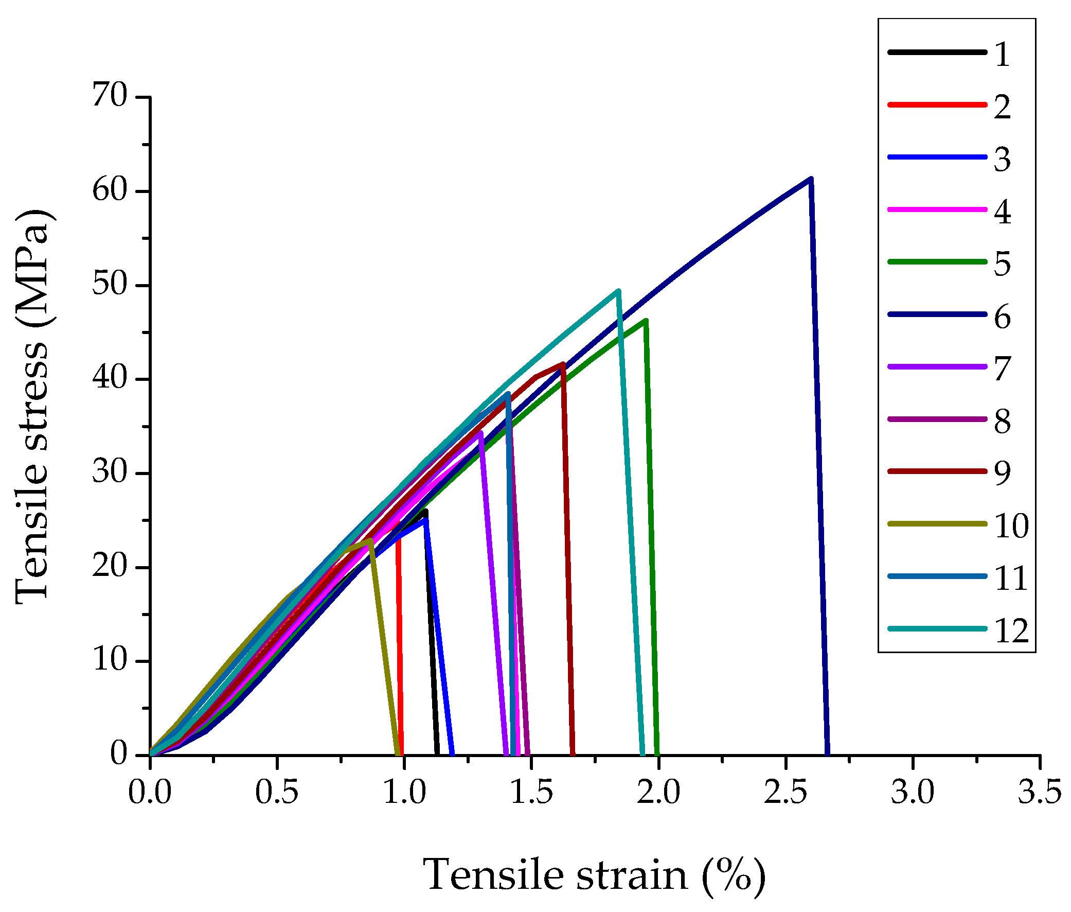
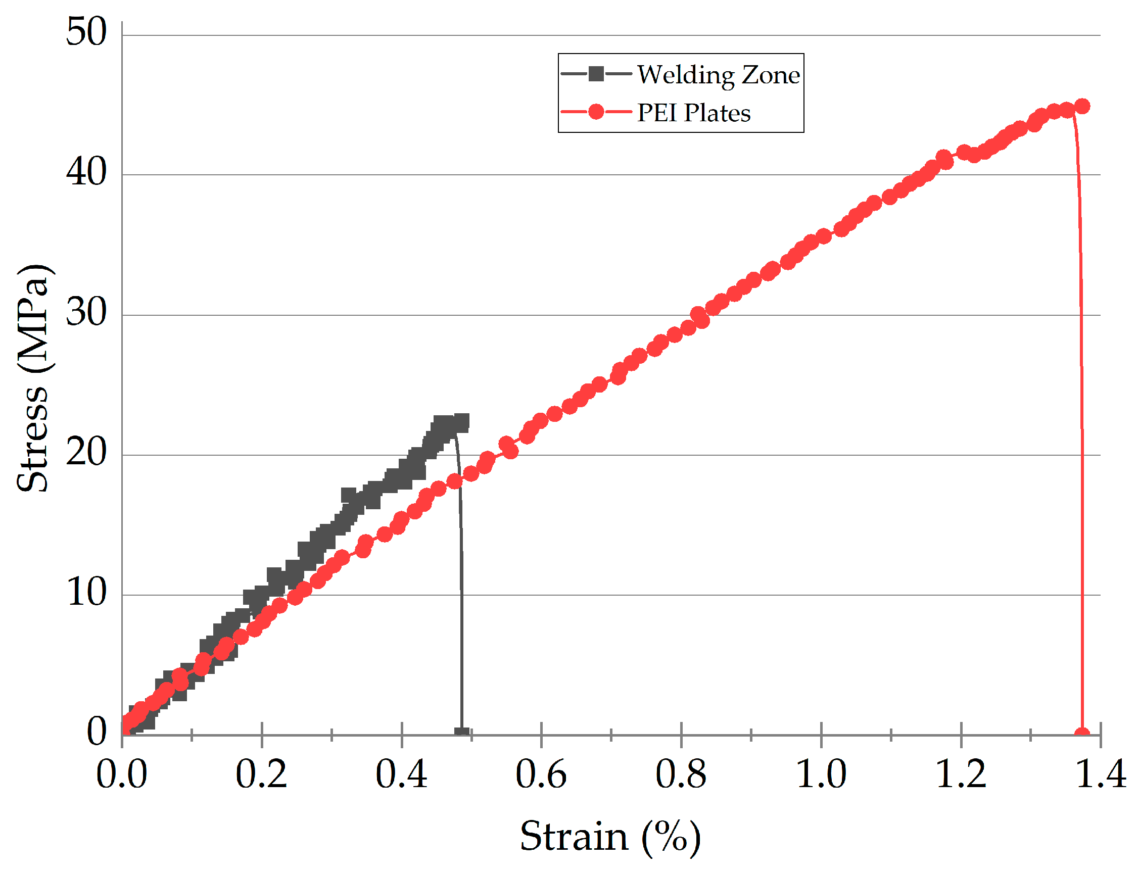
3.1. Tensile Tests

Stress–strain diagrams of the TecaPEI joints are presented in Figure 1. All of them were characterized by almost the same inclination angles, so ones with the greatest values of elongation at break possessed the maximum strength characteristics. Despite the similar shapes of the loading diagrams, the failure mechanisms were different. Taken together with the results of the fractured samples analysis (Figure 2), several characteristic groups could be identified.
The first group included the TecaPEI lap joints obtained using modes #1, 2, 3, and #10 (at the minimum USW duration of 400 ms). They possessed low UTS values of 22–26 MPa and fractured through the EDsTecaPEI, which was just partially melted during the USW process. At the same time, fragments of the fractured EDsTecaPEI film remained partially adhered on the surfaces of the PEI plates, confirming, along with the stress–strain diagrams, adhesive bonding (Figure 2a–c,j). On the other hand, the preservation of the initial (yellow) shade of the EDsTecaPEI indicated that they were just partially (locally) melted.
The second group consisted of the TecaPEI lap joints obtained using modes #5 and #6 (t = 500 ms, P = 1.7–1.9 atm). They had high UTS values of 46–61 MPa and failed through the PEI plates near their junctions with the fusion zones (Figure 2e,f).
The third group included the TecaPEI lap joints obtained using modes #4 (t = 500 ms, P = 1.5 atm) as well as #7, 8 and #9 (t = 600 ms, P = 1.5–1.9 atm). They were characterized by average UTS levels of 34–41 MPa and a cohesive failure pattern. The main cracks propagated along the melted EDsTecaPEI (Figure 2d,g–i). Considering the color and consistency of the EDsTecaPEI (loose structure), it could be concluded that not only did complete melting occur, but there was also partial thermal damage. Thus, the prolonged USW durations (≥600 ms) contributed to deterioration of the structure and properties of the EDsTecaPEI.
Modes #11 and 12 were related the last group of the TecaPEI lap joints, which possessed fairly high UTS values of 38–49 MPa. Their failure mechanism exhibited the adhesive-cohesive pattern, with fracturing through the center of the fusion zones (Figure 2k,l). The main cracks initiated at their junctions with the PEI adherends (which were stress raisers) and propagated along the interlayer interface. This phenomenon caused additional bending of the PEI plates [37], so the high adhesion level slowed down the process, according to the authors. The final fracture stage was of a cohesive type.
Based on the above, the implementation of modes #5, 6, 11 and #12 resulted in the improved mechanical properties of the TecaPEI lap joints.
Figure S1 shows photographs of the top PEI plate, adjacent to the sonotrode during the USW process. At USW durations of t = 400 and 500 ms (modes 1–6), less pronounced damage to the PEI plates was observed (at their corners mostly, Figure S1a–f). As the USW durations increased to t = 600 ms (modes #7–9), this process accelerated significantly, causing greater damage to the corner regions (Figure S1g–i). Unfortunately, increasing the clamping force to 2.1 atm did not prevent such deterioration in the integrity of the TecaPEI lap joints (Figure S1k,l).

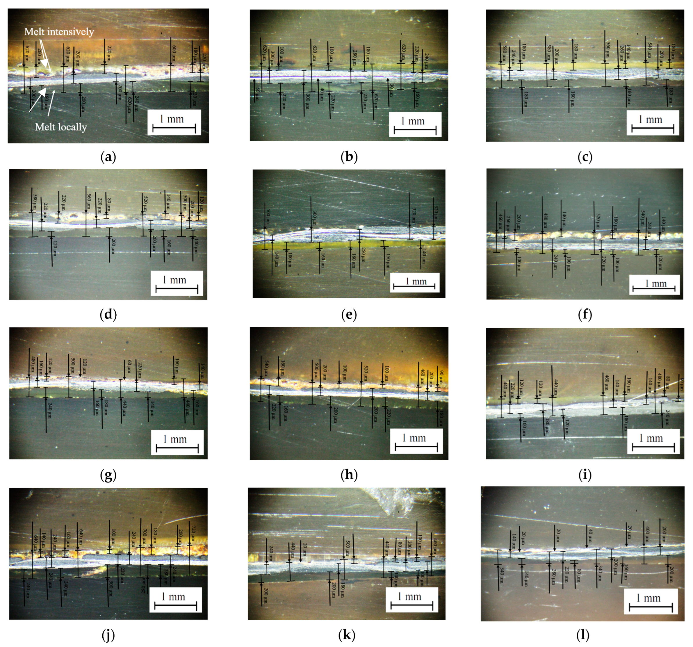
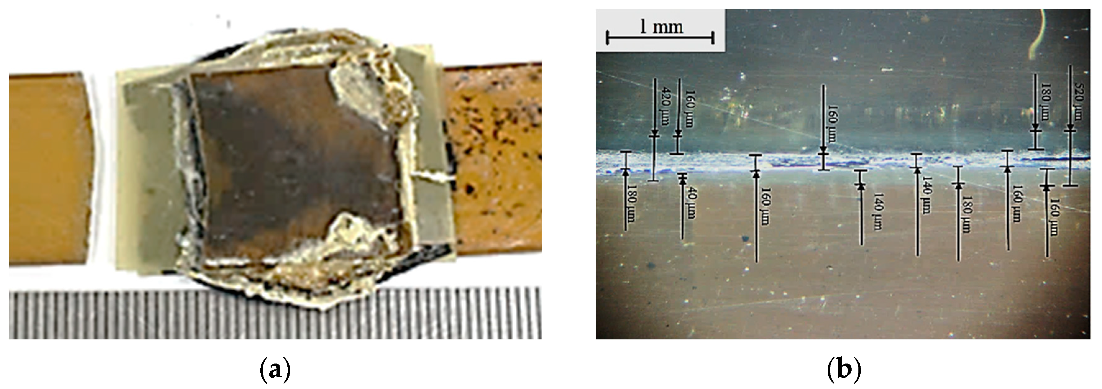
3.2. Cross-Section Structure

Figure 3 shows photographs of cross-sections of the TecaPEI lap joints, while Table 3 presents the summarized mechanical properties and structural (geometric) characteristics. During the formation of the TecaPEI lap joint using mode #1 (t = 400 ms, P = 1.5 atm), the top EDTecaPEI melted intensively, so its thickness was only 140 ± 40 μm (Figure 4a) in contrast to the initial value of 250 µm.
According to the authors, the low clamping force was a probable reason for this phenomenon. At the same time, the bottom EDTecaPEI did not melt locally, or was predominantly melted. As a result, its thickness was 220 ± 40 µm, being close to the initial value. USW lap joint thinning of 110 ± 60 µm reduced the mechanical properties down to the UTS of 26.0 MPa and the value of elongation at break of 1.13%.
A subsequent increase in the clamping force to 1.7 and 1.9 atm prevented (to a certain extent) frictional heating of the joined components, since it restrained their mutual movement during the USW process. As a result, (Table 3) the USW joint thinning values did not exceed 160 and 230 µm for the TecaPEI lap joints obtained using modes #2 (t = 400 ms, P = 1.7 atm) and #3 (t = 400 ms, P = 1.9 atm), respectively. At the same time, the thicknesses of the EDsTecaPEI differed slightly. The “CF layer” thickness of ~230 µm remained virtually unchanged relative to the initial value. Since melting of the EDsTecaPEI did not practically occur (Figure 3b,c) at such a short USW duration, reliable US-welded TecaPEI lap joints did not form. Their UTS strength values were 24–26.0 MPa at values of elongation at break of 0.98–1.19% (Table 3). In both cases, the top EDsTecaPEI melted to a lesser extent as compared to the clamping force of 1.5 atm (mode #1).
After the increase in USW duration to t = 500 ms, both the PEI binder in the prepreg and the EDsTecaPEI melted actively due to the frictional heating intensification upon the formation of the TecaPEI lap joint. The application of the mode #4 (t = 500 ms, P = 1.5 atm) resulted in USW lap joint thinning of ~160 µm, while the thicknesses of the top and bottom EDsTecaPEI were 150 ± 70 and 160 ± 40 µm, respectively (Table 3). The “CF layer” thickness was 190 ± 70 µm, i.e., decreased by 50–60 µm. The UTS was 35.2 MPa at a value of elongation at break of 1.44%. Increasing the clamping force to 1.7 and 1.9 atm was accompanied by more intense melting of both the binder in the prepreg and (partially) the EDTecaPEI. As a result, USW lap joint thinning values were 120 and 400 µm, respectively. Visually, the CF fabric (prepreg) retained its structural integrity, so the UTS levels were 46.2 and 61.3 MPa, respectively (Table 3). In fact, the use of mode #6 improved the mechanical properties of the TecaPEI lap joints while visually maintaining the structural integrity of their components.
After increasing USW duration to 600 ms, increased frictional heat melted the EDsTecaPEI greatly. As a result, USW lap joint thinning was 360 µm for modes #7 and 8, while it was 420 µm for mode #9 (Table 3). At the same time, the thicknesses of the top EDsTecaPEI decreased significantly down to 20–160 μm. Average UTS levels were 34.3–41.6 MPa.
When using mode #10 (t = 400 ms, P = 2.1 atm), it did not have enough time to melt the EDsTecaPEI in some regions (Figure 3j) due to both the short USW duration and the high clamping force. As a result, the UTS was low (22.9 MPa according to Table 3). USW lap joint thinning increased, compared to that for mode #3.
USW lap joint thinning was 240 µm (Table 3) on the use of mode #11 (t = 500 ms, P = 2.1 atm). In this case, the “CF layer” thickness of 220 ± 40 µm approximately corresponded to the initial value. The UTS reached 38.5 MPa (Table 3), confirming the formation of a reliable TecaPEI lap joint.
The application of mode 12 (t = 600 ms, P = 2.1 atm) caused USW lap joint thinning of ~500 µm (Table 3). In this case, the thickness of the top EDTecaPEI was 30 ± 30 µm (it almost completely squeezed out), while it was 150 ± 70 µm for the bottom one. The CF layer thickness was 180 ± 40 µm (Table 3). The UTS was 49.4 MPa at a value of elongation at break of 1.94%. Despite the improved mechanical properties, thermal damage to both the EDsTecaPEI (discussed below) and the top PEI plate does not allow us to recommend this USW mode for any industrial applications.
Since mode #6 was characterized by the rational USW parameters, according to the criterion of the maximum mechanical properties, let us briefly summarize the structural (geometric) characteristics of the TecaPEI lap joint, according to Table 3. Its USW joint thinning was 400 ± 40 μm, which confirmed the melting of the components. The thickness of the EDsTecaPEI was reduced by at least 100 μm while the prepreg became thinner by 50–60 μm. It was obvious that minimal damage to the prepreg (primarily to the reinforcing CF fabric in its composition) was a prerequisite for the USW process. However, it was not possible to avoid melting of the prepreg since it only contained PEI as a polymer binder.
Taking into account the above-mentioned fact of the influence of macrobending of the TecaPEI lap joints in the tensile tests [37], the improvement of the mechanical properties could not be the only criterion for optimizing USW parameters. For this reason, an analysis of the structural (geometric) characteristics of the one obtained using mode #5 (Table 3) was also carried out. Its USW lap joint thinning of 120 ± 20 μm was more negligible. The preservation of the prepreg integrity was confirmed by the “CF layer” thickness of 250 ± 110 µm, i.e., it was at the initial level. Therefore, the main contribution to USW lap joint thinning was the melting of the EDsTecaPEI down to 120 ± 60 and 160 ± 20 µm for the both top and bottom ones, respectively, which was their main destination. Thereby, the thinning of each of the EDsTecaPEI did not exceed 100 µm on average.

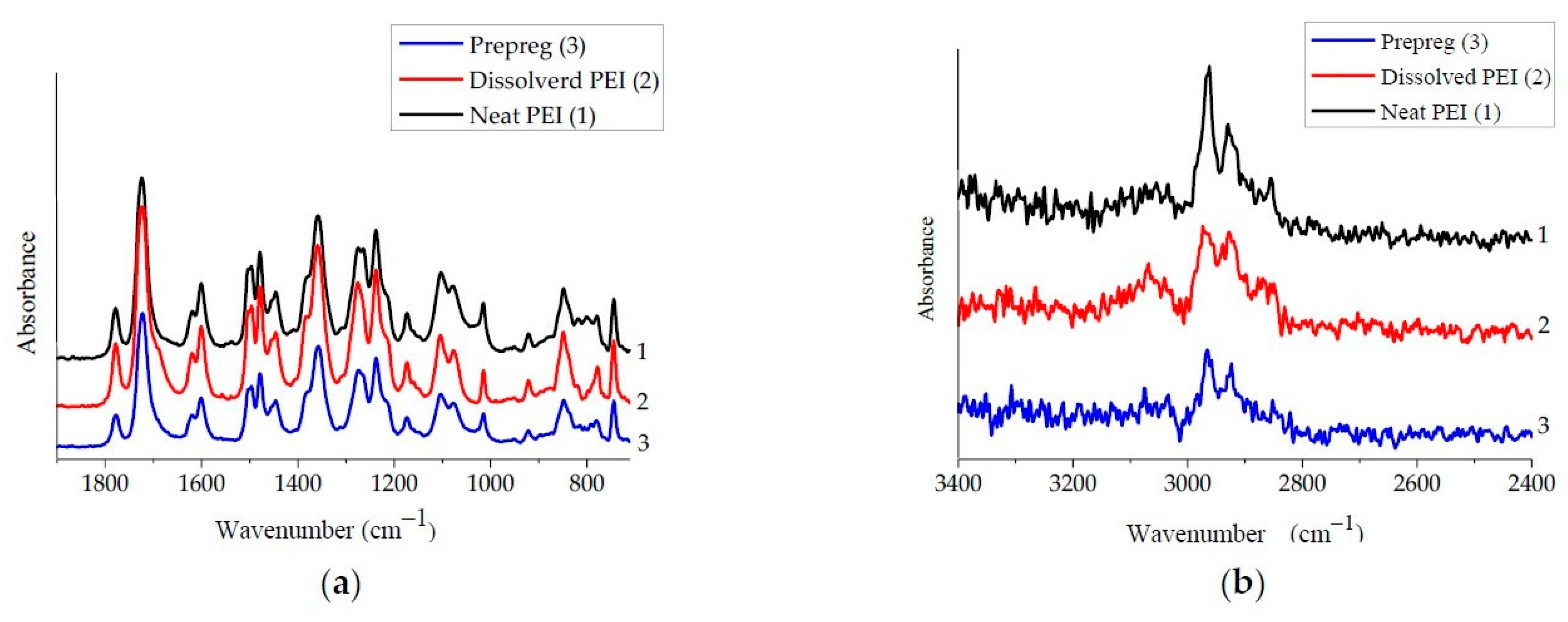
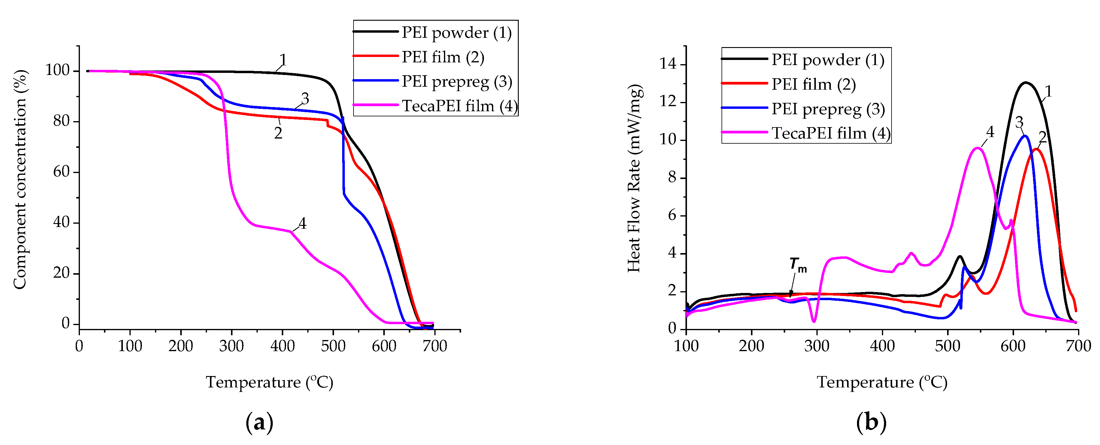
3.3. Chemical Structure

To assess possible changes in the chemical structure of PEI during its dissolution and subsequent hot pressing in the production rout of the prepreg, FTIR spectra of the original PEI powder, the film fabricated from its solution, and the polymer in the prepreg were analyzed for two ranges of reciprocate wavelengths of 500–2000 and 2500–3250 cm−1 (Figure 5). The lowest intensity of peaks was characteristic of PEI in the prepreg (Figure 4a,b), although the FTIR spectra were similar in terms of their appearance and positions.
On the other hand, major qualitative differences were found for the neat PEI powder and the film (ED) fabricated from its solution. Firstly, several maxima were evident in the region of 782–831 cm−1 (Figure 4a), as well as a peak at a reciprocate wavelength of 2854 cm−1. This meant that degradation of the polymer did not occur due to its dissolution in N-methylpyrralidone (C5H9NO) and subsequent evaporation of the solvent. However, its thermophysical characteristics could be changed. To verify this fact, combined DSC-TGA curves were registered (Figure 5).
The melting point of the neat PEI powder was approximately 266 °C (Figure 5b; curve 1). It did not undergo thermal degradation to temperatures of below T < 450 °C, since no weight loss was revealed in this range (Figure 5a; curve 1). After the dissolution, PEI showed signs of weight loss already at T~150 °C (Figure 5a; curve 2). The most likely reason was incomplete evaporation of the solvent and its removal during the TGA analysis. However, this fact could facilitate easier spreading of the PEI binder in the prepreg during the USW process. In addition, the melting point reduced slightly down to 262 °C (Figure 5b; curve 2). This result was important to illustrate the fact that dissolving PEI in N-methylpyrralidone (C5H9NO) increased its processability in terms of facilitating melt flow.
However, the TGA data on the TecaPEI film should be considered as the most indicative (Figure 5a; curve 4). Already at temperatures above T > 200 °C, sharp weight loss was revealed, which showed the thermal degradation of PEI (according to the authors, this was not the deterioration of PEI, but rather of the plasticizing component within the TecaPEI film). At temperatures above T > 300 °C, weight loss of the TecaPEI film was ~40%. At the same time, its melting temperature was ~297 °C according to the DSC data (Figure 5b; curve 4). This level was even higher than that for the neat PEI powder and its solution in N-methylpyrralidone (Figure 5b). To a certain extent, the obtained result explained the intense spreading of the molten TecaPEI film in the USW process, facilitating the formation of the TecaPEI joints. However, such a sharp weight loss at temperatures below the melting point is unlikely to have improved the mechanical properties of the interlayer.
Since the structure of the EDs underwent complex changes during the USW process, associated with (i) the influence of the USW with the applied parameters on the pattern of their melting and deformation; (ii) the different kinetics of the development of such processes, both in the top and bottom EDs; and (iii) mixing the surface layer material of the prepreg contacting PEI adherends, it was decided to perform model experiments that made it possible to draw more unambiguous conclusions on this topic.

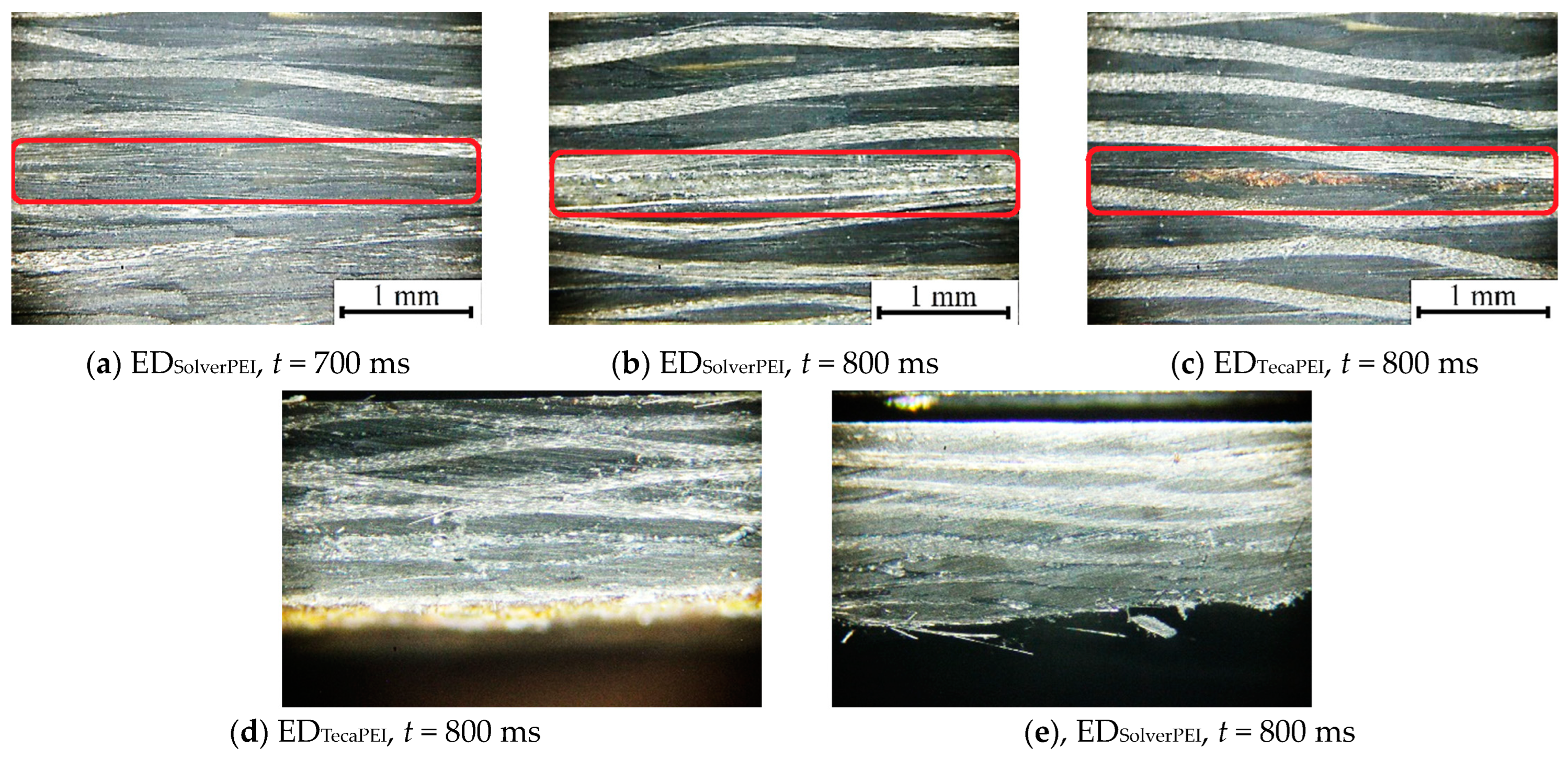
4. Application of Both Low-Melting TecaPEI and PEI Films for USW Consolidation of the CF Fabric–PEI Laminates
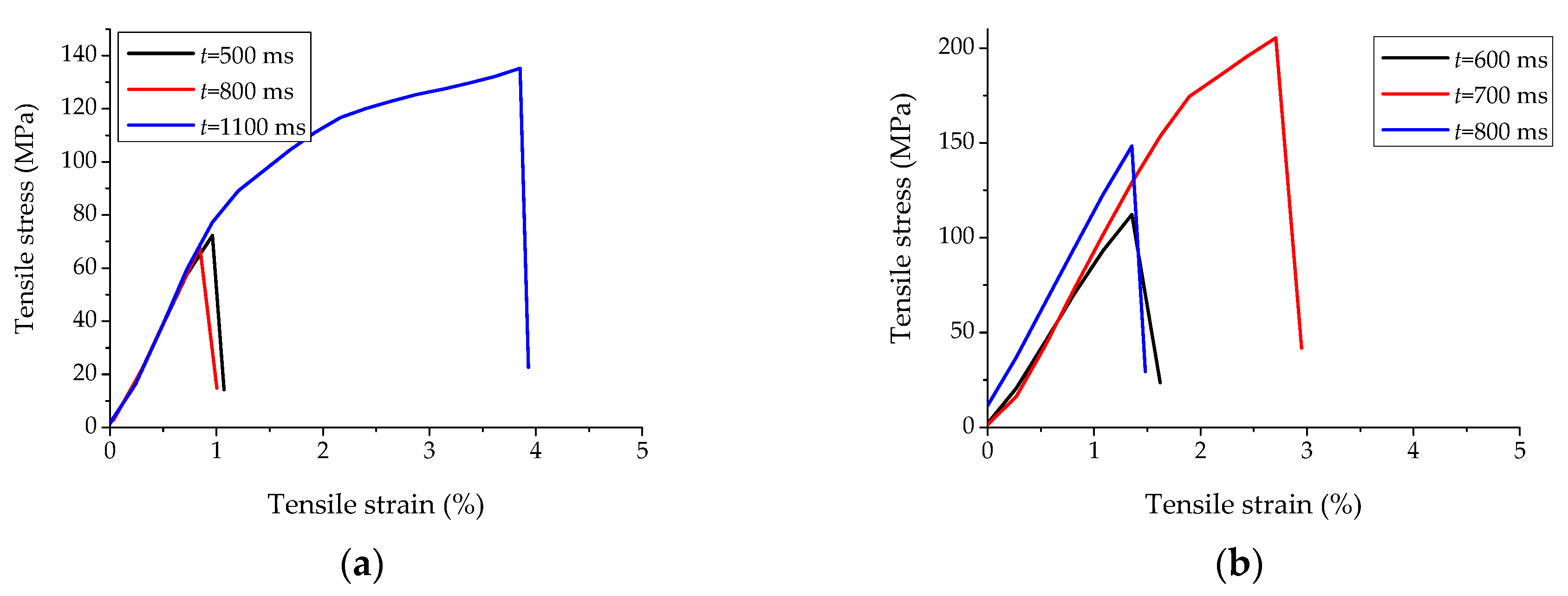
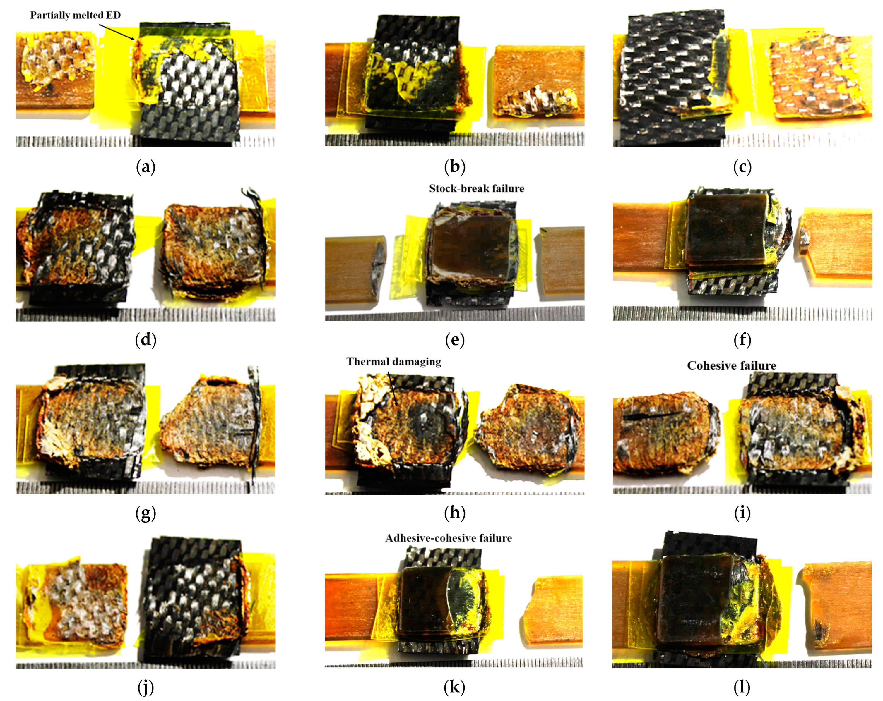
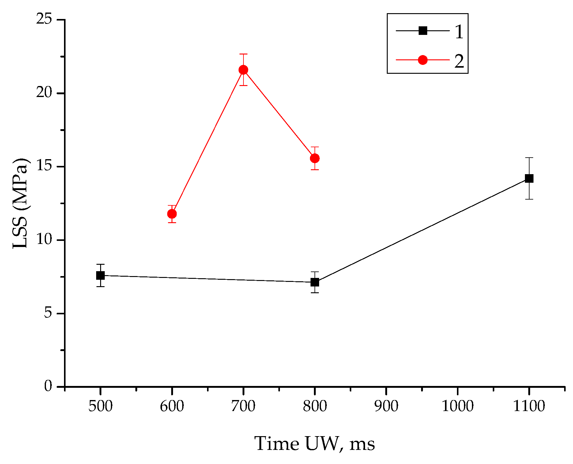
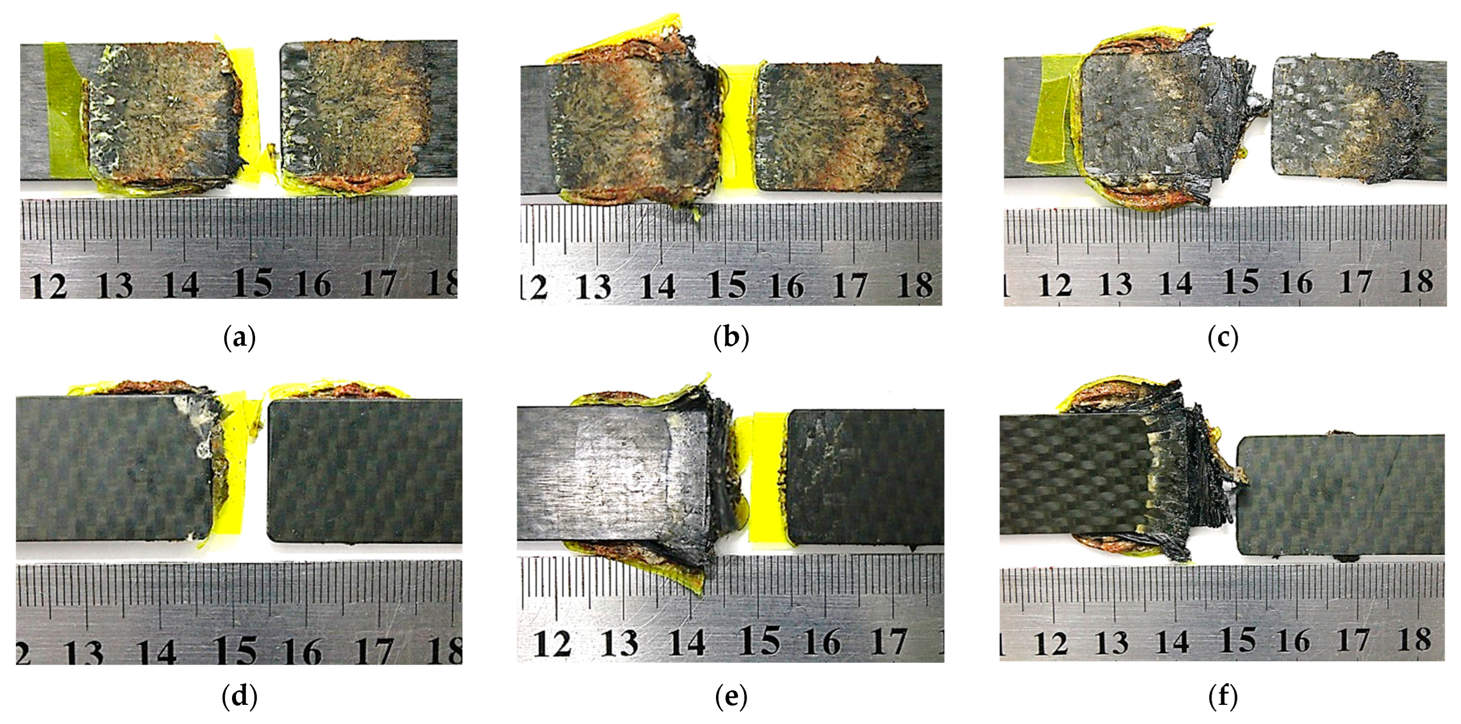
Since most published data on USW procedures for thermoplastic composites were focused on laminates, a comparative study of two types of EDs for USW of the CF fabric–PEI laminates was conducted. In the first case, the TecaPEI film was used, as in the previous section. In addition, the film of the same thickness, made from the neat PEI Solver powder by hot pressing under the laboratory conditions, was utilized. It was highlighted in Section 2 that the use of the CF fabric–PEI laminates as adherends affected USW development. Therefore, USW parameters differed from those for the PEI plates due to variations in the transmission of ultrasonic vibrations from the sonotrode to the fusion zone through the significantly stronger and stiffer CF fabric–PEI laminate.

4.1. Tensile Tests

Figure 6 shows engineering stress–strain diagrams for all studied cases. At USW durations of t = 500 and 800 ms, the EDTecaPEI lap joints were characterized by both a low UTS of ~70 MPa and values of elongation at break of 1%. After increasing t to 1100 ms, the UTS increased to 135 ± 8 MPa at an elongation at break of 4%. For the EDSolverPEI lap joints, the maximum mechanical properties were achieved at a USW duration of 700 ms. In this case, the UTS was 205 ± 10 MPa at an elongation at break of ~3%, further decreasing as USW duration increased to t = 800 ms.
Figure 7 shows the LSS versus USW duration dependencies. Higher LSS values were typical for the EDSolverPEI lap joints (the maximum level of 21.6 ± 1.3 MPa was achieved at t = 700 ms). The obtained result was superior to previously published data for the PEI-based laminates, and slightly inferior to those based on polyphenylsulfide (PPS). For example, LSS was 16.5 MPa for the US-welded PEI-based laminates [38], while it was 33.5 ± 1.4 MPa for the PPS-based ones [3].
Figure 8 shows general views of the fractured EDTecaPEI lap joints after the tensile tests, including those characterizing damage to the CF fabric–PEI laminate adjacent to the sonotrode in the USW process. At t = 500 and 800 ms, they failed via the adhesive fracture mechanism (Figure 8a,b). In the fusion zone, where the main crack propagated, the EDTecaPEI residues were evident. The polymer partially changed color, most likely due to thermal degradation. USW lap joint thinning was 190–210 µm (Table 4), which was comparable to the initial EDTecaPEI thickness.
At a USW duration of t = 1100 ms, partial damage to the top CF fabric–PEI adherend (adjacent to the sonotrode) was evident (Figure 8c). No remaining EDTecaPEI parts were found in the fusion zone, and USW lap joint thinning was ~390 µm (Table 4). This fact indicated both complete melting and squeezing out of the EDTecaPEI from the fusion zone, as well as melting and deformation of the binder in the top CF fabric–PEI adherend, leading to partial damage (Figure 8f). At t = 500 and 800 ms, there was practically no damage to the top CF fabric–PEI adherend adjacent to the sonotrode (Figure 8d,e).
Figure 9 shows general views of the EDSolverPEI lap joints after the tensile tests and the damage pattern of the top CF fabric–PEI adherend adjacent to the sonotrode in the USW process. At USW durations of t = 600 and 700 ms, they exhibited an adhesive failure mechanism (Figure 9a,b). At t = 700 ms, USW lap joint thinning was 220 μm, which was greater only by 20 μm than that at t = 600 ms. In the first case, few residual EDSolverPEI parts were found in the fusion zone, which corresponded to the maximum LSS value of 21.6 MPa (Table 4).
At a maximum USW duration of t = 800 ms applied for the EDSolverPEI lap joints, the surface layer of the top CF fabric–PEI adherend was locally damaged in the tensile test (Figure 9c). This fact was in good agreement with USW lap joint thinning of 400 µm (Table 4). The latter indicated that melting of both the EDSolverPEI and the PEI binder occurred in the locally damaged top CF fabric–PEI adherend (Figure 9f). At t = 600 and 700 ms, this phenomenon was expressed to a minimum extent (Figure 9d,e).
According to Figure 7, LSS values were low for the EDTecaPEI lap joints, not exceeding ~7 MPa at t = 500 ms. After increasing USW duration to 800 ms, they remained virtually unchanged. However, a twofold increase in the LSS value to 14.2 MPa was observed at t = 1100 ms. The reason was damage to the top CF fabric–PEI adherend, so such USW parameters are not to be applied for any practical applications.
For the EDSolverPEI lap joints, changes in LSS values were extreme, the maximum level of which reached 21.6 MPa at t = 700 ms. In this case, the EDSolverPEI melted more completely without damaging the top CF fabric–PEI adherend in the USW process.

4.2. Cross-Section Structure

Figure 10a–c shows optical images of cross-sections of the EDTecaPEI and EDSolverPEI lap joints before the tensile tests. For the EDTecaPEI lap joints, the integrity of the components was preserved at t = 800 ms (Figure 10c), and adhesive fracture proceeded strictly through the EDTecaPEI upon testing (marked with a frame in Figure 10d). The initial structure of the laminates did not change, and no pores or interlayer delamination were formed during the USW process (Figure 10c).
For the EDSolverPEI lap joints, the fusion zone was thin and homogeneous at t = 800 ms (marked by a frame in Figure 10a), while a thick layer of a structurally inhomogeneous material, remaining after melting the EDSolverPEI, was found at the interface of the laminates at t = 800 ms (marked with a frame in Figure 10b). During the tensile test, the main crack did not propagate along the fusion zone (Figure 10e), most likely because the CF fabric–PEI adherend adjacent to the sonotrode was damaged during the USW process (Figure 9e).
In light of the obtained results, a question arose: if the EDTecaPEI did not provide high LSS values compared to those for the EDSolverPEI, how promising was its practical application? As the authors found, if the PEI plates were joined (similar to the results described in Section 3), and the interlayer was the CF fabric–PEI prepreg, melting of the EDSolverPEI occurred later (which required the prolongation of USW duration to 750 ms). However, such USW processes were accompanied by damage to both the top PEI plate (Figure 11a) and the CF fabric–PEI prepreg (Figure 11b).

5. Discussion

Among the key factors affecting the mechanical properties and the structural (geometric) characteristics of the USW lap joints, at least four were identified above. Firstly, there was the macroscopic bending phenomenon during the tensile tests, caused by the increased stiffness (rigidity) of the fusion zone (the mechanical factor). Secondly, there was the presence of macro-stress raisers at the junctions of the PEI plates with the fusion zone (the structural–mechanical factor). Thirdly, there was the structural heterogeneity of the fusion zone, even when using the optimal USW parameters (the structural factor). Fourthly, there was both incomplete melting and possible degradation of the EDs during the USW process (the structural factor). All of these were not controlled (technological/input) parameters, but could have had a significant impact on the mechanical properties (response/output) of the USW lap joints through the formation of their structures.

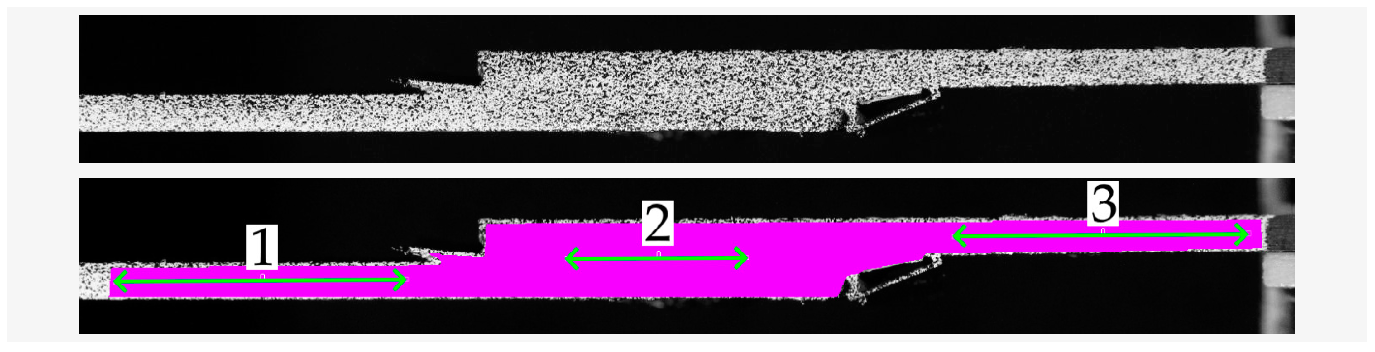
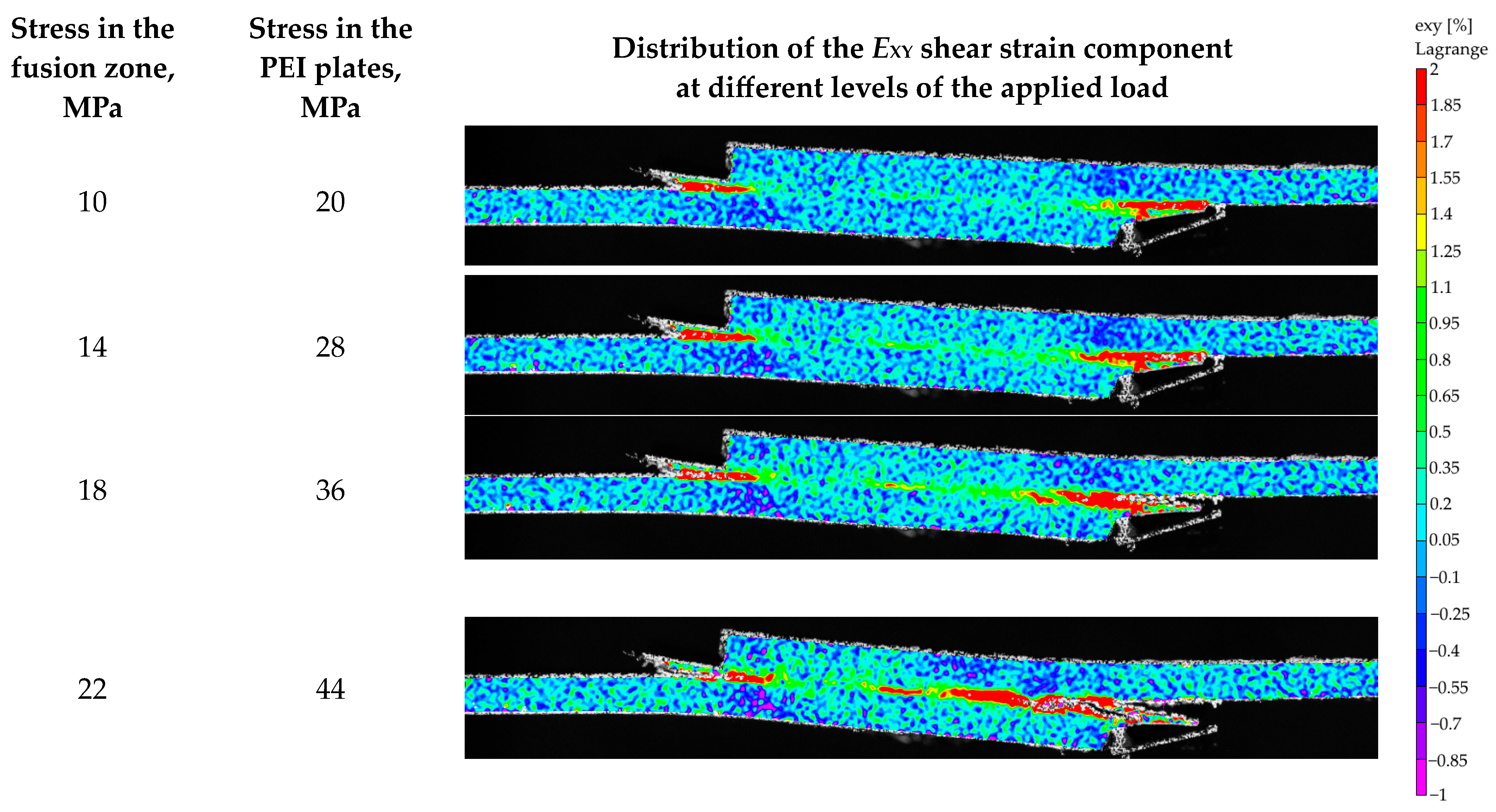
5.1. Deformation Behavior Characterization by the DIC Method

The DIC method [39,40] was applied to experimentally confirm the macroscopic bending of the USW lap joints during the tensile tests (previously investigated by computer simulation based on the finite-element method [37]), as well as to assess strain distributions in both the PEI plates and the fusion zone. The TecaPEI lap joint fabricated using mode #5 was tested under static tension at a cross-head speed of 1 mm/min. Strains were measured in three regions using optical extensometers (Figure 12).
Regions 1 and 3 characterized strains in the PEI plates in their junction with the fusion zone, while region 2 corresponded to the development of strains in the fusion zone. The calculations assumed a cross-sectional size of the PEI plates of 2 × 20 mm for regions 1 and 3, and 4 × 20 mm for region 2. Average strains at locations 1 and 3 are shown in a strain–stress diagram as a curve for the PEI plates (Figure 13). Table 5 presents the mechanical properties of the two regions of the TecaPEI lap joint fabricated using mode #5, calculated from the data recorded with both the force gauge of the testing machine and the optical extensometers. According to these results, the elastic modulus was noticeably higher for the fusion zone than that for the PEI plates. At the same time, both UTS and values of elongation at break were two or more times greater for the PEI plates than for the fusion zone.
Figure 14 shows the fields of the (EXY) shear strain component upon loading of the TecaPEI lap joint fabricated using mode #5. Firstly, the strain distribution in both the PEI plates and the fusion zone could not be considered absolutely uniform. Secondly, the development of macroscopic bending was obvious, the magnitude of which increased as the applied load increased (despite the use of compensating gaskets when clamping the TecaPEI joint to the grips, prescribed by the test standard [41]). Thirdly, the main crack was initiated on the right side of the fusion zone, gradually propagating adhesively over a certain distance, followed by cohesive fracture along the PEI plate. With the magnification used, it was impossible to trace in more detail which component failed, but the final general view of the fractured TecaPEI lap joint corresponded to that shown in Figure S1f. Thus, both the development of macroscopic bending and the presence of macro-stress raisers at the junctions of the PEI plates with the fusion zone were confirmed experimentally.

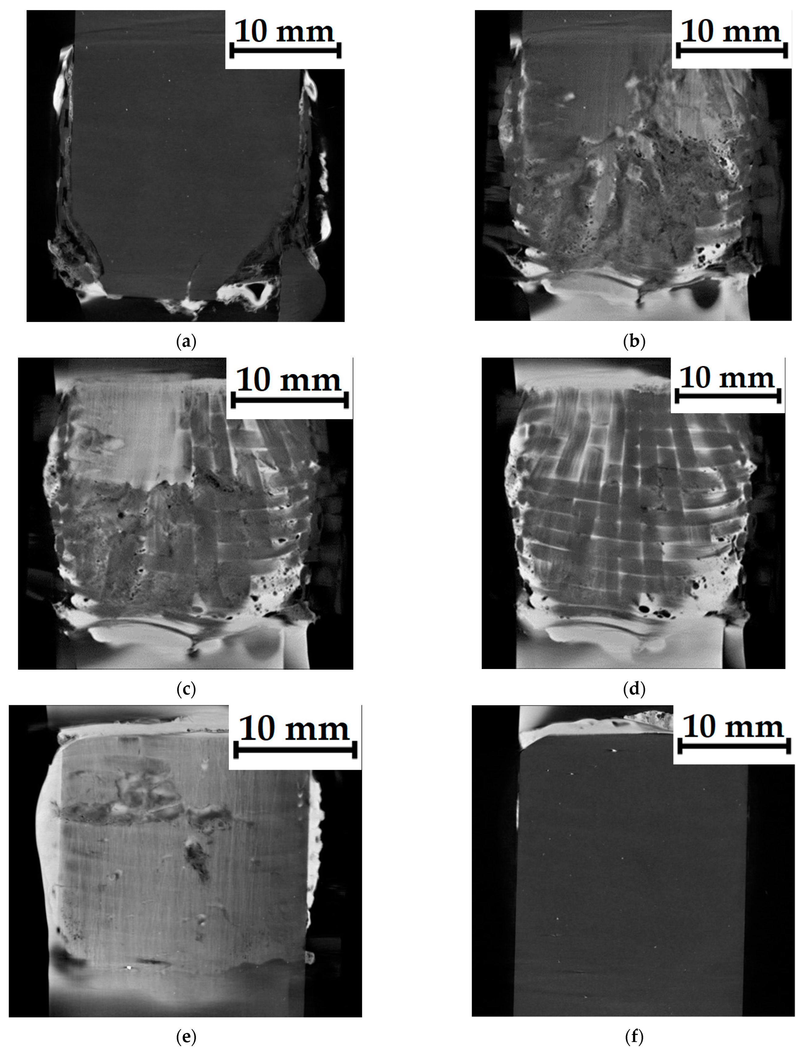
5.2. Computed Tomography

As shown above in Section 3, the structure of the USW lap joints was not uniform: (i) the final thicknesses of the top and bottom EDs varied; (ii) the prepregs might be plastically deformed; (iii) the corners of the top PEI plates might be damaged, etc. Several structural factors were mentioned above that affected the development of strains in the EDTecaPEI lap joints. In order to qualitatively assess the structure of the fusion zone in the TecaPEI lap joint formed using mode #5, it was examined with the use of a CT, the results of which are shown in Figure 15 in the form of planar slices-sections.
Corners of the top PEI plate (adjacent to the sonotrode during the USW process) were slightly damaged (Figure 15a). The top ED partially possessed a loose structure with some pores (the lower half of Figure 15b), while its upper part was quite dense. The CF fabric, as part of the prepreg, retained its structural integrity (Figure 15d), although it was not characterized by laying in one plane (Figure 15c). The bottom ED had a dense structure, but with local discontinuities (Figure 15e). Finally, the bottom PEI plate retained its structural integrity (Figure 15f).

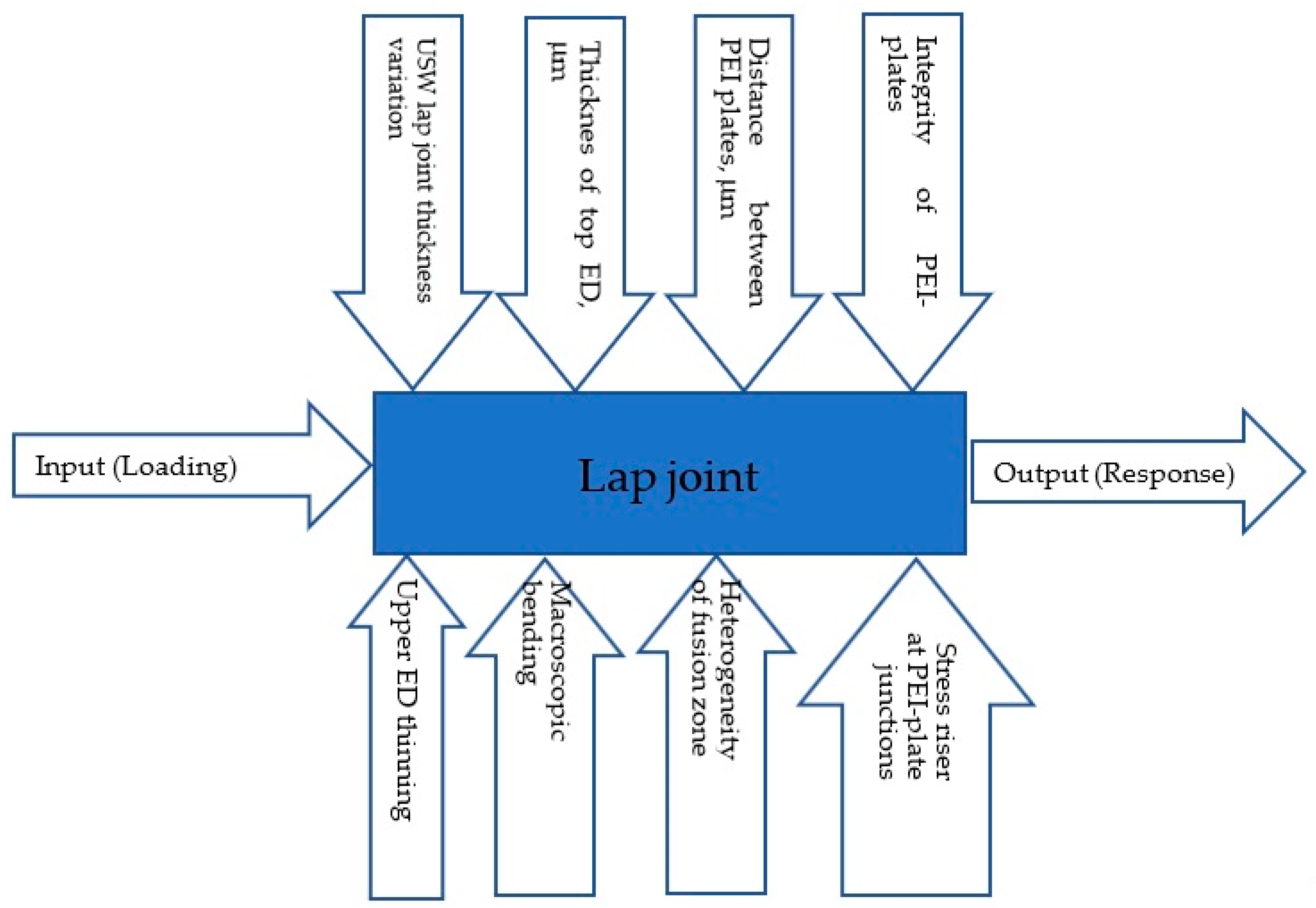
5.3. Process Analysis

So, the use of the near-optimal USW parameters (mode #5) enabled improving the mechanical properties of the USW lap joints, but did not guarantee the formation of their completely homogeneous structure. In part, this problem could be related to the technical specification of the deployed USW machine, but the authors preferred to avoid a discussion of this aspect.
As a generalization of the data reported in the Discussion section, the authors proposed a scheme that includes both key controlled and quantitatively uncontrolled factors that determined the deformation response of the USW lap joints (Figure 16). The proposed scheme considered the approach outlined in a book on the DOE [42]. The top part of the scheme consists of the key controlled structural parameters presented in Table 3, while the bottom part includes the factors (although not all) discussed in the experimental data analysis, or mentioned above regarding both the DIC and CT results. The proposed scheme enabled summarizing the obtained data on the one hand; and on the other, it showed that the results of optimization of USW parameters could not be absolutely accurate, although they made it possible to take into account the maximum extent of the diversity of the processes occurring in the short-term USW procedures for joining the PEI plates with the CF fabric–PEI prepreg and the low-melting EDTecaPEI.

5.4. USW Consolidation of a PEEK-Based Prepreg

The authors suggested the following point as a perspective for research development. In the Introduction section, they cited a number of papers dedicated to laminates fabricated via USW consolidation of both thermoplastic films and CF tapes, for example [43]. In so doing, an attempt was made to apply USW parameters close to mode 5 (optimized in this research) to form a similar multilayer (laminate) structure via USW consolidation of a PEEK-based prepreg and the “Toray Cetex TC1200” film (140 μm thick) from unidirectional CFs. An optical cross-sectional image of such a laminate without any prepregs is presented in Figure 17a. The laying pattern for eight layers was [0/90]. Another similar image for the laminate with the low-melting TecaPEI is shown in Figure 17b. The EDsTecaPEI was located between six layers of the prepreg with constant characteristic distances between them (all were structurally intact).
Finally, the following statements should be highlighted. A distinctive feature of the used TecaPEI film was the possibility to quickly melt and easily flow. This phenomenon made it possible to reduce the sonotrode’s damaging effect on the top joined plates due to shorter USW durations. As a result, the joints were formed, possessing a UTS of over 60 MPa (mode 6). However, the low thermal stability led to thermal degradation. Therefore, such a material provided significantly lower LSS values when used as an ED compared to hot-pressed PEI powder. Accordingly, the TecaPEI film can be used when very high interlayer adhesion values are not required, for example due to short USW durations and minimal damaging effects on the components to be joined.

6. Conclusions

In order to estimate the possibility of using the low-melting TecaPEI film as an ED for USW consolidation of the CF fabric–PEI laminates, patterns of the structure formation and the mechanical properties of such lap joints were investigated experimentally by varying the process parameters. The experiment was planned by the Taguchi method with the L9 orthogonal matrix. Based on the obtained results, USW parameters that enable maintaining the structural integrity of the joined components and improving their functional characteristics were optimized.
It was shown that the use of the EDTecaPEI enabled USW-joining the laminates with minimal damage to the fusion zone. However, the achieved LSS values of ~7.6 MPa were extremely low. On the other hand, the EDSolverPEI with a higher melting point eliminated thermal degradation of the components, making it possible to achieve competitive LSS values above 21 MPa.
With the use of DIC and CT methods, the structural factors affecting the deformation behavior of the USW lap joints were justified, including (i) the macroscopic bending phenomenon during the tensile tests; (ii) the presence of macro-stress raisers at the junctions of the PEI plates with the fusion zone; (iii) the structural heterogeneity of the fusion zone, even with the use of optimal USW parameters; (iv) both incomplete melting and possible degradation of the EDs during the USW process.
A scheme was proposed that reflects the relationship between the controlled and uncontrolled structural factors and the deformation response of the USW lap joints under static tension. At the same time, the criterion for the quality of the laminates was the preservation of the structural integrity of the PEI plates, corners of which were damaged at long USW durations due to the amorphous structure and fragility. It can be useful in the development of the integrated approach to optimize USW parameters for the manufacture of the CF fabric–PEI laminates.
A TecaPEI film can be utilized in USW procedures (including for consolidation of multilayer laminates) due to short USW durations and minimal damaging effects on the components being joined when very high interlayer adhesion properties are not required.

Supplementary Materials

The following supporting information can be downloaded at: https://www.mdpi.com/article/10.3390/jcs8040150/s1, Figure S1: The pattern of damage to the PEI adherend adjacent to the sonotrode during the formation of the TecaPEI joints.

Author Contributions

Conceptualization, S.V.P. and V.O.A.; methodology, S.V.P. and V.O.A.; validation, V.O.A.; formal analysis, V.O.A., D.G.B. and S.V.P.; investigation, V.O.A., A.A.B., D.T. and D.G.B.; resources, D.G.B.; data curation, D.T. and V.O.A.; writing—original draft preparation, S.V.P. and V.O.A.; writing— review and editing, S.V.P.; visualization, V.O.A. and D.T.; funding acquisition, D.G.B. and D.T. All authors have read and agreed to the published version of the manuscript.

Funding

The research was funded by the ISPMS SB RAS, project FWRW-2021-0010.

Data Availability Statement

The data presented in this study are available in this article.

Acknowledgments

The authors acknowledge Mikhail Burkov, a senior researcher of Institute of Strength Physics and Materials Science (ISPMS) SB RAS, for providing PEEK prepregs used in the experiments. Fourier-transform infrared spectroscopy was carried out using facilities at Institute of Petroleum Chemistry SB RAS. TG/DSC analysis was performed at the “Physico-chemical methods of analysis” center of Tomsk Polytechnic University (TPU). Fractographic examinations were conducted with setups of the “Nanotech” center of ISPMS SB RAS. X-ray microtomography was performed at the School of Non-Destructive Testing of TPU.

Conflicts of Interest

The authors declare no conflict of interest.

References

  1. Gallego-Juárez, J.A.; Graff, K.F. Power Ultrasonics: Applications of High-Intensity Ultrasound; Elsevier: Amsterdam, The Netherlands, 2015; pp. 295–312. [Google Scholar]
  2. Li, W.; Palardy, G. Investigation of welding repair methods for thermoplastic composite joints. Compos. Part B Eng. 2023, 264, 110924. [Google Scholar] [CrossRef]
  3. Ullah, M.A.; Li, W.; Palardy, G. Effect of ultrasonic welding process parameters on the crystallinity of GF/MWCNT/PP composites. In Proceedings of the American Society for Composites, Greater Boston, MA, USA, 17–20 September 2023. [Google Scholar]
  4. Li, W.; Frederick, H.; Palardy, G. Multifunctional films for thermoplastic composite joints: Ultrasonic welding and damage detection under tension loading. Compos. Part A Appl. Sci. Manuf. 2020, 141, 106221. [Google Scholar] [CrossRef]
  5. Bonmatin, M.; Chabert, F.; Bernhart, G.; Cutard, T.; Djilali, T. Ultrasonic welding of CF/PEEK composites: Influence of welding parameters on interfacial temperature profiles and mechanical properties. Compos. Part A Appl. Sci. Manuf. 2022, 162, 107074. [Google Scholar] [CrossRef]
  6. Jongbloed, B.; Teuwen, J.; Villegas, I.F. On the use of a rounded sonotrode for the welding of thermoplastic composites. J. Adv. Join. Process. 2023, 7, 100144. [Google Scholar] [CrossRef]
  7. Tsiangou, E.; de Freitas, S.T.; Villegas, I.F.; Benedictus, R. Investigation on energy director-less ultrasonic welding of poly-etherimide (PEI)-to epoxy-based composites. Compos. B Eng. 2019, 173, 107014. [Google Scholar] [CrossRef]
  8. Reis, J.P.; de Moura, M.; Samborski, S. Thermoplastic composites and their promising applications in joining and repair composites structures: A review. Materials 2020, 13, 5832. [Google Scholar] [CrossRef] [PubMed]
  9. Kumar, R.; Singh, R.; Ahuja, I.; Penna, R.; Feo, L. Weldability of thermoplastic materials for friction stir welding- A state of art review and future applications. Compos. Part B Eng. 2018, 137, 1–15. [Google Scholar] [CrossRef]
  10. Yan, J.C.; Wang, X.L.; Li, R.Q.; Xu, H.B.; Yang, S.Q. The Effects of Energy Director Shape on Temperature Field during Ultrasonic Welding of Thermoplastic Composites. Key Eng. Mater. 2007, 353–358, 2007–2010. [Google Scholar] [CrossRef]
  11. Palardy, G.; Villegas, I.F. On the effect of flat energy directors thickness on heat generation during ultrasonic welding of thermoplastic composites. Compos. Interfaces 2017, 24, 203–214. [Google Scholar] [CrossRef]
  12. Khatri, B.; Roth, M.F.; Balle, F. Ultrasonic Welding of Additively Manufactured PEEK and Carbon-Fiber-Reinforced PEEK with Integrated Energy Directors. J. Manuf. Mater. Process. 2023, 7, 2. [Google Scholar] [CrossRef]
  13. Tsiangou, E.; de Freitas, S.T.; Villegas, I.F.; Benedictus, R. Ultrasonic welding of epoxy- to polyetheretherketone- based composites: Investigation on the material of the energy director and the thickness of the coupling layer. J. Compos. Mater. 2020, 54, 3081–3098. [Google Scholar] [CrossRef]
  14. Villegas, I.F.; van Moorleghem, R. Ultrasonic welding of carbon/epoxy and carbon/PEEK composites through a PEI thermoplastic coupling layer. Compos. Part A Appl. Sci. Manuf. 2018, 109, 75–83. [Google Scholar] [CrossRef]
  15. Zhao, P.; Zhang, Z.; Li, Y.; Tian, L.; Wang, C.; Xiong, X. Resistance welding of thermoplastic composites via a novel carbon nanofilm implant. Mater. Lett. 2022, 328, 133216. [Google Scholar] [CrossRef]
  16. Marques, L.F.B.; Reis, J.F.; Abrahão, A.B.R.M.; Hein, L.R.D.O.; Botelho, E.C.; Costa, M.L. Interfacial, mechanical, and thermal behavior of PEI/glass fiber welded joints influenced by hygrothermal conditioning. J. Compos. Mater. 2021, 56, 239–249. [Google Scholar] [CrossRef]
  17. Gao, J.; Dong, J.; Zhang, S.; Yu, L.; Jin, H.; Zhang, J.; Shen, Y. Study of friction stir spot welding for thermotolerant engineering thermoplastic polyimide joints. Proc. Inst. Mech. Eng. Part B J. Eng. Manuf. 2021, 235, 1810–1817. [Google Scholar] [CrossRef]
  18. Chu, Q.; Li, Y.; Xiao, J.; Huan, D.; Zhang, X.; Chen, X. Processing and characterization of the thermoplastic composites man-ufactured by ultrasonic vibration–assisted automated fiber placement. J. Thermoplast. Compos. Mater. 2018, 31, 339–358. [Google Scholar] [CrossRef]
  19. Kirby, M.; Naderi, A.; Palardy, G. Predictive Thermal Modeling and Characterization of Ultrasonic Consolidation Process for Thermoplastic Composites. J. Manuf. Sci. Eng. 2023, 145, 031009. [Google Scholar] [CrossRef]
  20. Slange, T.K.; Grouve, W.J.; Warnet, L.L.; Wijskamp, S.; Akkerman, R. Towards the combination of automated lay-up and stamp forming for consolidation of tailored composite components. Compos. Part A Appl. Sci. Manuf. 2019, 119, 165–175. [Google Scholar] [CrossRef]
  21. Forcellese, A.; Greco, L.; Pieralisi, M.; Simoncini, M.; Trevisan, G. Mechanical properties of carbon fiber reinforced plastic obtained by the automatic deposition of an innovative towpreg. Procedia CIRP 2020, 88, 451–456. [Google Scholar] [CrossRef]
  22. Struzziero, G.; Barbezat, M.; Skordos, A.A. Consolidation of continuous fibre reinforced composites in additive processes: A review. Addit. Manuf. 2021, 48, 102458. [Google Scholar] [CrossRef]
  23. Gomer, A.; Zou, W.; Grigat, N.; Sackmann, J.; Schomburg, W.K. Fabrication of Fiber Reinforced Plastics by Ultrasonic Welding. J. Compos. Sci. 2018, 2, 56. [Google Scholar] [CrossRef]
  24. Lionetto, F.; Dell’Anna, R.; Montagna, F.; Maffezzoli, A. Modeling of continuous ultrasonic impregnation and consolidation of thermoplastic matrix composites. Compos. Part A Appl. Sci. Manuf. 2015, 82, 119–129. [Google Scholar] [CrossRef]
  25. Esfandiari, P.; Silva, J.F.; Novo, P.J.; Nunes, J.P.; Marques, A.T. Production and processing of pre-impregnated thermoplastic tapes by pultrusion and compression moulding. J. Compos. Mater. 2022, 56, 1667–1676. [Google Scholar] [CrossRef]
  26. Yao, S.-S.; Jin, F.-L.; Rhee, K.Y.; Hui, D.; Park, S.-J. Recent advances in carbon-fiber-reinforced thermoplastic composites: A review. Compos. Part B Eng. 2018, 142, 241–250. [Google Scholar] [CrossRef]
  27. Minchenkov, K.; Vedernikov, A.; Safonov, A.; Akhatov, I. Thermoplastic Pultrusion: A Review. Polymers 2021, 13, 180. [Google Scholar] [CrossRef] [PubMed]
  28. Tao, W.; Su, X.; Wang, H.; Zhang, Z.; Li, H.; Chen, J. Influence mechanism of welding time and energy director to the ther-moplastic composite joints by ultrasonic welding. J. Manuf. Process. 2019, 37, 196–202. [Google Scholar] [CrossRef]
  29. Kupski, J.; Teixeira de Freitas, S. Design of adhesively bonded lap joints with laminated CFRP adherends: Review, challenges and new opportunities for aerospace structures. Compos. Struct. 2021, 268, 113923. [Google Scholar] [CrossRef]
  30. SCase, W.; Das, A.; Bortner, M.J.; Dillard, D.A.; White, C.C. Durability and accelerated characterization of adhesive bonds. In Advances in Structural Adhesive Bonding; Dillard, D.A., Ed.; Woodhead Publishing: Sawston, UK, 2023; pp. 675–710. ISBN 9780323912143. [Google Scholar]
  31. Panda, H.S.; Samant, R.; Mittal, K.L.; Panigrahi, S. Durability Aspects of Structural Adhesive Joints. In Structural Adhesive Joints: Design, Analysis and Testing; Mittal, K.L., Panigrahi, S.K., Eds.; Wiley: Hoboken, NJ, USA, 2020. [Google Scholar] [CrossRef]
  32. Alexenko, V.O.; Panin, S.V.; Stepanov, D.Y.; Byakov, A.V.; Bogdanov, A.A.; Buslovich, D.G.; Panin, K.S.; Tian, D. Ultrasonic Welding of PEEK Plates with CF Fabric Reinforcement—The Optimization of the Process by Neural Network Simulation. Materials 2023, 16, 2115. [Google Scholar] [CrossRef]
  33. Ding, G.; Feng, P.; Wang, Y.; Ai, P. Novel pre-clamp lap joint for CFRP plates: Design and experimental study. Compos. Struct. 2022, 302, 116240. [Google Scholar] [CrossRef]
  34. Taguchi, G.; Phadke, M.S. Quality Engineering through Design Optimization. In Quality Control, Robust Design, and the Taguchi Method; Springer: Boston, MA, USA, 1984. [Google Scholar]
  35. Kacker, R.N.; Lagergren, E.S.; Filliben, J.J. Taguchis’s Orthogonal Arrays are Classical Design of Experiments. J. Res. Natl. Inst. Stand. Technol. 1991, 96, 577. [Google Scholar] [CrossRef]
  36. Taguchi, G. System of Experimental Design: Engineering Methods to Optimize Quality and Minimize Costs; Quality Resources: New York, NY, USA, 1987. [Google Scholar]
  37. Panin, S.V.; Bochkareva, S.A.; Panov, I.L.; Alexenko, V.O.; Byakov, A.V.; Lyukshin, B.A. Experimental and Numerical Studies on the Tensile Strength of Lap Joints of PEEK Plates and CF Fabric Prepregs Formed by Ultrasonic Welding. In Progress in Continuum Mechanics. Advanced Structured Materials; Altenbach, H., Irschik, H., Porubov, A.V., Eds.; Springer: Berlin/Heidelberg, Germany, 2023; Volume 196, pp. 321–354. [Google Scholar]
  38. Wang, J.; Lu, C.; Xiao, C.; Cheng, J.; Ren, R.; Xiong, X. Heat distribution simulation and effects of ultrasonic welding amplitude on carbon fiber/polyetherimide composite joint properties. Mater. Lett. 2023, 340, 134148. [Google Scholar] [CrossRef]
  39. Sutton, M.A.; Orteu, J.J.; Schreier, H.W. Image Correlation for Shape, Motion and Deformation Measurements: Basic Concepts, Theory and Applications; Springer: New York, NY, USA, 2009; 316p. [Google Scholar]
  40. Bogdanov, A.A.; Panin, S.V.; Lyubutin, P.S.; Eremin, A.V.; Buslovich, D.G.; Byakov, A.V. An Automated Optical Strain Measurement System for Estimating Polymer Degradation under Fatigue Testing. Sensors 2022, 22, 6034. [Google Scholar] [CrossRef] [PubMed]
  41. D5868-01 2014; Standard Test Method for Lap Shear Adhesion for Fiber Reinforced Plastic (FRP) Bonding. ASTM International: West Conshohocken, PA, USA, 2023.
  42. Antony, J. Design of Experiments for Engineers and Scientists, 2nd ed.; Elsevier: Waltham, MA, USA, 2014; p. 208. [Google Scholar]
  43. Xiong, H.; Hamila, N.; Boisse, P. Consolidation Modeling during Thermoforming of Thermoplastic Composite Prepregs. Materials 2019, 12, 2853. [Google Scholar] [CrossRef] [PubMed]
Figure 1. The strain–stress diagrams for the TecaPEI lap joints.
Jcs 08 00150 g001
Figure 2. General views of the TecaPEI joints fractured in the tensile tests; USW duration (t), ms/clamping force (P), atm/holding time (τ), ms: (a) #1—400/1.5/3000; (b) #2—400/1.7/5000; (c) #3—400/1.9/7000; (d) #4—500/1.5/5000; (e) #5—500/1.7/7000; (f) #6—500/1.9/3000; (g) #7—600/1.5/5000; (h) #8—600/1.7/3000; (i) #9—600/1.9/5000; (j) #10—400/2.1/3000; (k) #11—500/2.1/3000; (l) #12—600/2.1/3000.
Jcs 08 00150 g002
Figure 3. The optical images of the cross-sections of the TecaPEI lap joints; USW duration (t), ms/clamping force (P), atm/holding time (τ), ms: (a) #1—400/1.5/3000; (b) #2—400/1.7/5000; (c) #3—400/1.9/7000; (d) #4—500/1.5/5000; (e) #5—500/1.7/7000; (f) #6—500/1.9/3000; (g) #7—600/1.5/5000; (h) #8—600/1.7/3000; (i) #9—600/1.9/5000; (j) #10—400/2.1/3000; (k) #11—500/2.1/3000; (l) #12—600/2.1/3000.
Jcs 08 00150 g003
Figure 4. The FTIR spectra for the original PEI powder (1), the film fabricated from its solution (2), and PEI in the prepreg (3); wavenumber of 800–1800 cm−1 (a); wavenumber of 2400–3400 cm−1 (b).
Jcs 08 00150 g004
Figure 5. The TGA (a) and DSC (b) diagrams for the original PEI powder (1), the film fabricated from its solution (2), PEI in the prepreg (3), and the TecaPEI film (4).
Jcs 08 00150 g005
Figure 6. The engineering stress–strain diagrams for the EDTecaPEI (a) and EDSolverPEI (b) lap joints.
Jcs 08 00150 g006
Figure 7. The LSS versus USW duration dependencies for the EDTecaPEI (1) and EDSolverPEI (2) joints.
Jcs 08 00150 g007
Figure 8. The general views of the EDTecaPEI lap joints after the tensile tests (ac) and the damage pattern of the top CF fabric–PEI adherend adjacent to the sonotrode in the USW process (df): (a,d) t = 500 ms; (b,e) t = 800 ms; (c,e) t = 1100 ms.
Jcs 08 00150 g008
Figure 9. General views of the EDSolverPEI lap joints after the tensile tests (ac) and the damage pattern of the top CF fabric–PEI adherend adjacent to the sonotrode in the USW process (df): (a,d) t = 600 ms; (b,e) t = 700 ms; (c,e) t = 800 ms.
Jcs 08 00150 g009
Figure 10. The optical images of the cross-sections of the CF fabric–PEI laminates as part of the EDTecaPEI (a,b,e) and EDSolverPEI (c,d) lap joints; fusion zones are marked by a red frame.
Jcs 08 00150 g010
Figure 11. A general view of the EDSolverPEI lap joint after the tensile test (a) and an optical image of its cross-section (b); t = 750 ms.
Jcs 08 00150 g011
Figure 12. An optical image of the side face of the TecaPEI lap joints with the applied speckle and the locations of the optical (software Vic 2D 2009) extensometers. Green arrows indicate the length of gauge zones 1–3.
Jcs 08 00150 g012
Figure 13. The strain–stress diagrams for both the fusion zone (region 2) and the PEI plates (by averaging over regions 1 and 3), calculated using the DIC method.
Jcs 08 00150 g013
Figure 14. The fields of the (EXY) shear strain component upon loading of the TecaPEI lap joint formed using mode #5.
Jcs 08 00150 g014
Figure 15. The CT data for the TecaPEI joint formed using mode #5. Top PEI plate (a); top ED (b); CF fabric in the prepreg (c,d); bottom ED (e); bottom PEI plate (f).
Jcs 08 00150 g015
Figure 16. A schematic representation of both controllable (at the top) and uncontrollable (at the bottom) factors that determined the deformation response of the USW lap joints.
Jcs 08 00150 g016
Figure 17. The optical photographs of cross-sections of the laminates, fabricated via USW consolidation of the PEEK/CF prepregs and the “Toray Cetex TC1200” film from unidirectional CFs: (a) without ED; (b) with the EDTecaPEI.
Jcs 08 00150 g017
Table 1. Combinations of the factors and their levels in the L9 format, expanded to 12 experiments based on a priori information from the authors.
No.Level/Factor
USW Duration (t), msClamping Force (P), atmHolding Time (τ), ms
(1)4001.53000
(2)4001.75000
(3)4001.97000
(4)5001.55000
(5)5001.77000
(6)5001.93000
(7)6001.57000
(8)6001.73000
(9)6001.95000
Additional USW modes
(10)4002.13000
(11)5002.13000
(12)6002.13000
Table 2. The parameters of the “Orel-MT” X-ray microtomograph.
Spatial Tomogram Resolution, µmUp to 5
X-ray machineXWT 160-TC (X-RAY WorX)
Anode voltage, kV20–255
Anode current, µA0.05–1.00
Focal spot, µm0.9
Detector panelPaxScan-2520V (Varian)
Size of detector elements, µm127
Detector operating area, mm193 × 242
Matrix size, pixel1900 × 1516
Table 3. The mechanical properties and the structural (geometric) characteristics of the TecaPEI lap joints.
No.Ultimate Tensile Strength (σP), MPaElongation at Break (ε), mmUSW Joint Thinning (Δd), μmED Photo (δED top), μmED Photo (δED bottom), μmDistance between PEI Plates (δED+CF), μmCF Layer Thickness (δCF), μmPEI Plate Integrity
(+/−)
126.0 ± 1.61.13 ± 0.05110 ± 60210 ± 50220 ± 40620 ± 20230 ± 30+
224.7 ± 1.70.98 ± 0.06160 ± 30160 ± 60200 ± 40600 ± 20230 ± 70+
325.0 ± 1.51.19 ± 0.07230 ± 20170 ± 30180 ± 40550 ± 30210 ± 50+
435.2 ± 1.41.44 ± 0.07160 ± 20150 ± 70160 ± 40540 ± 40210 ± 50+
546.2 ± 3.21.99 ± 0.10120 ± 20120 ± 60160 ± 20550 ± 50250 ± 110+
661.3 ± 3.12.66 ± 0.11400 ± 40160 ± 40140 ± 40500 ± 40190 ± 70+
734.3 ± 2.11.40 ± 0.07360 ± 20100 ± 60170 ± 70430 ± 70200 ± 60
838.2 ± 2.31.49 ± 0.07290 ± 20120 ± 40170 ± 50480 ± 60180 ± 40
941.6 ± 1.71.66 ± 0.08420 ± 20120 ± 60170 ± 70440 ± 40150 ± 70
1022.9 ± 1.10.97 ± 0.06190 ± 10200 ± 100200 ± 100670 ± 50240 ± 40+
1138.5 ± 2.31.43 ± 0.08240 ± 1070 ± 50180 ± 20460 ± 40220 ± 40
1249.4 ± 3.01.94 ± 0.11500 ± 4040 ± 20160 ± 80360 ± 60180 ± 40
Table 4. The mechanical properties and the structural (geometric) characteristics of the EDTecaPEI and EDSolverPEI lap joints.
ED TypeUSW Duration (t), msUSW Lap Joint Thinning (Δd), μmUltimate Tensile Strength (σP), MPaElongation at Break
P), %
LSS, MPa
ED TecaPEI
TecaPEI500190 ± 3072.2 ± 4.11.1 ± 0.27.6 ± 0.4
TecaPEI800210 ± 4067.9 ± 3.41.0 ± 0.27.1 ± 0.4
TecaPEI1100390 ± 90135.0 ± 8.03.9 ± 0.314.2 ± 0.6
ED Solver PEI
Solver PEI600200 ± 30112.2 ± 9.01.6 ± 0.211.8 ± 0.6
Solver PEI700220 ± 30205.4 ± 10.02.9 ± 0.221.6 ± 1.3
Solver PEI800400 ± 90148.3 ± 9.01.5 ± 0.215.6 ± 0.8
Table 5. The mechanical properties of both the fusion zone and the PEI plates of the TecaPEI lap joint fabricated using mode #5.
MaterialUltimate Tensile Strength (σP), MPaElastic Modulus (E), GPaElongation at Break (ε), %
Fusion zone22.5 ± 0.74.5 ± 0.20.49 ± 0.02
PEI plates44.9 ± 1.83.1 ± 0.11.37 ± 0.05
Disclaimer/Publisher’s Note: The statements, opinions and data contained in all publications are solely those of the individual author(s) and contributor(s) and not of MDPI and/or the editor(s). MDPI and/or the editor(s) disclaim responsibility for any injury to people or property resulting from any ideas, methods, instructions or products referred to in the content.

