Article

Electrochemical Jet Machining of Surface Texture: Improving the Strength of Hot-Pressure-Welded AA6061-CF/PA66 Joints

1
College of Aeronautical Engineering, Civil Aviation University of China, Tianjin 300300, China
2
Department of Mechanical and Energy Engineering, Southern University of Science and Technology, Shenzhen 518055, China
3
School of Materials Science and Engineering, Tianjin University, Tianjin 300354, China
*
Authors to whom correspondence should be addressed.
J. Compos. Sci. 2024, 8(7), 263; https://doi.org/10.3390/jcs8070263 (registering DOI)
Submission received: 15 May 2024 / Revised: 19 June 2024 / Accepted: 5 July 2024 / Published: 7 July 2024
(This article belongs to the Special Issue Carbon Fiber Composites, Volume III)

Abstract

:
Diverse industries are witnessing an increase in demand for hybrid structures of metals and carbon-fiber-reinforced thermoplastic composites (CFRTPs). Welding is an essential technique in the manufacture of metal–CFRTP hybrid structures. However, achieving high-strength metal–CFRTP welded joints faces serious challenges due to the considerable disparities in material characteristics. As an effective method to strengthen metal–CFRTP joints, surface texturing on metal is gaining significant attention. This study introduces an emerging surface texturing approach, electrochemical jet machining (EJM) using a film electrolyte jet, for enhancing the performance of AA6061-CF/PA66 hot-pressure-welded (HPW) joints. Parametric effects on surface morphology and roughness in the EJM of AA6061 are investigated. The results show that a rough surface with multiscale pores can be generated on AA6061 by EJM, and that surface morphology can be modulated by adjusting the applied current density and jet translational speed. Subsequently, the effects of different EJM-textured surface morphologies on the performance of HPW joints are examined. Surface textures created by EJM are demonstrated to significantly enhance the mechanical interlocking effect at the bonding interface between AA6061 and CF/PA66, resulting in a substantial increase in joint strength. The maximum joint strength attained in the present work with EJM texturing is raised by 45.29% compared to the joints without surface texturing. Additionally, the joint strength slightly improves as the roughness of EJM-textured surfaces rises, with the exception of rough surfaces that are textured with a combination of low current density and rapid translational speed. Overall, these findings suggest that EJM texturing using a film jet prior to welding is a potential approach for the manufacture of high-performance metal–CFRTP hybrid structures.

1. Introduction

Carbon-fiber-reinforced thermoplastic composites (CFRTPs) feature the advantages of low density, high strength, superior fatigue performance, excellent impact properties, and outstanding vibration resistance, making them a type of attractive material for a wide range of applications [1,2]. Meanwhile, with the development of optimized lightweight design via the usage of multi-materials, metal–CFRTP hybrid structures are emerging in various fields, such as the aerospace and automotive industries. For example, they are used in components such as engine cowlings, fairing and fixed trailing edges, wing panels, etc., in aircraft [3,4,5,6]. Due to the fact that welding is the major technique used to deal with the issue of joining metals and CFRTPs, its significance in the manufacture of metal–CFRTP hybrid structures continues to grow [6,7].
To date, various welding approaches have been developed for joining CFRTP with metal, including laser welding [8,9], friction welding [10,11], ultrasonic welding [12,13], hot pressure welding [14,15], and so on. In comparison to other approaches, hot pressure welding (HPW) has demonstrated significant promise for widespread application owing to its benefits such as simple equipment design, environmental sustainability, and ease of operation [5,16]. However, due to the substantial differences in the chemical and physical properties of metals and CFRTPs, achieving high-strength metal–CFRTP dissimilar joints encounters immense challenges [3]. When welding CFRTPs to metals, the bonding mechanism and the joint strength rely primarily on the interfacial mechanical interlock phenomena generated by heating, melting, and penetrating the CFRTP into the microscale scratches and craters on the metal surface. Additionally, chemical bonding may also form at the interface, further enhancing the joint strength. Accordingly, an effective method to improve the strength of metal–CFRTP HPW joints is creating surface textures on metals before welding to provide a more robust mechanical interlock effect [17]. Liu et al. employed laser texturing to create grooves with a width of several hundred micrometers on the surface of an AZ31B magnesium alloy to improve the HPW joint strength of AZ31B-CFRTP [18]. Abe et al. demonstrated that the strength of HPW joints of aluminum–CFRTP can be increased using nanoscale spike-like surface features prepared by two-cycle electrochemical anodizing and etching [19]. Iwata et al. enhanced A5052-CFRTP hot pressure weldability using laser additively manufactured particle-shaped protrusions with an average height and width of about 20 µm and 120 µm on the metal surface [20]. In addition, a number of studies on other metal–CFRTP welding methods have also confirmed the effectiveness of surface texturing approaches like micro-arc oxidation (MAO), sandblasting, and grinding to promote interfacial mechanical interlock. Xia et al. created tiny pores with an average diameter of a few micrometers on a TC4 titanium alloy surface via MAO and found that these tiny pores contribute to the strength enhancement of TC4-CFRTP laser-welded joints [21]. Dong et al. enhanced the strength of AA5052-CFRTP joints by sandblasting rough surfaces with cavities on aluminum alloy surfaces [22]. Nagatsuka et al. demonstrated the improving effect of metal surface grinding prior to friction lap welding on the strength of aluminum alloy–CFRTP joints [10]. Overall, these studies highlight the need for developing appropriate surface texture morphologies and corresponding manufacturing processes to facilitate the HPW of metals and CFRTPs.
Electrochemical jet machining (EJM) is an important and emergent variation of electrochemical machining [23]. EJM achieves targeted material removal by using an unsubmerged “free” electrolyte jet to restrict the electrochemical anodic dissolution in the jet-impinged area on metal workpiece surfaces [24,25]. This jet-based electrochemical process enables EJM to excel in the manufacture of microstructures and surface textures. Particularly, large-area surface textures with electrochemical-etched features can be selectively created on workpieces with high efficiency by applying a film-shaped jet and appropriate parameters. For example, Kunieda et al. demonstrated that EJM with a film jet can produce a grid-patterned texture on nickel surfaces [26]. Lyu et al. showed that surfaces textured by the film-jet EJM process enhance the AA5052–polymer joints created by injection molded direct joining [27]. For the purpose of creating antibacterial surfaces, Lutey et al. utilized the film-jet EJM process to create complicated porous structures on stainless steels, varying in size from a few to hundreds of micrometers [28,29]. Considering its technical traits, the film-jet EJM process is a potential surface texture preparation method for improving the strength of metal–CFRTP HPW joints.
This study, taking 6061 aluminum alloy and a carbon-fiber-reinforced nylon 66 composite material (CF/PA66) as the typical materials, aims to examine the feasibility of increasing metal–CFRTP HPW joint strength by generating surface textures via EJM using a film jet. For this, the parametric effects on surface texture morphology in the film-jet EJM process of AA6061 are investigated. HPW experiments with different surface texture morphologies created by EJM are conducted to investigate their impact on joint performance.

2. Materials and Methods

2.1. Materials

This study utilized 6061 aluminum alloy (AA6061) and carbon-fiber-reinforced PA66 (CF/PA66) as the experimental materials. The dimensions of the AA6061 sheets and CF/PA66 sheets were 100 × 40 × 1.5 mm3 and 100 × 40 × 3 mm3, respectively. The used CF/PA66 sheets (Grivory® GCL-4H, EMS-CHEMIE (China) Ltd., Suzhou, China) were injection-molded and comprised 40 wt.% carbon fibers with a diameter of 7 μm and a length of approximately 10 mm. The main physical properties of AA6061 and CF/PA66 are listed in Table 1.

2.2. EJM of Textured Surfaces Using a Film Jet

Figure 1 depicts the principle of the EJM process using a film jet. The film-shaped electrolyte jet is ejected from a cathodic slit nozzle onto an anodic workpiece. After the film jet impinges the workpiece, the electrolyte changes the flow direction and flows rapidly to the surrounding region, creating a thin electrolyte layer around the jet. Further away from the jet, the thickness of this electrolyte layer suddenly increases due to the hydraulic jump phenomenon. The “free” jet surface and the surrounding thin electrolyte layer restrict the dispersion of the electrical field, making the electrochemical dissolution take place only in the jet-impinged region [23]. Generally, the current density distribution on the anodic surface exhibits a Gaussian-like profile [24]. As a result, the workpiece surface beneath the slit nozzle can be textured with electrochemical-etched features under suitable machining conditions [28,29]. Further, with the designed translating path of the nozzle, large-area surface textures can be selectively created on the workpiece surface.
In this study, a home-made EJM prototype, illustrated in Figure 2, was employed for texturing AA6061 surfaces. The EJM apparatus comprised a direct current power supply, a numerically controlled positioning platform, and an electrolyte circulation system. Table 2 lists the machining parameters in the EJM experiments. A commonly used ECM electrolyte, an aqueous solution of 20 wt.% NaCl, was chosen as the electrolyte. The cross-sectional width of the slit nozzle was 0.1 mm to produce a thin-film electrolyte jet. A constant flow velocity of 4.28 m/s was used to ensure the stable configuration of the “free” film jet, surrounding thin fluid layer, and hydraulic jump phenomenon. In order to investigate the influence of current density and jet translational speed on the surface texture morphologies created by EJM, areal current densities ranging from 20 to 300 A/cm2 and translational speeds ranging from 0.25 to 5 mm/s were employed. To maintain consistent material removal for surfaces textured under various conditions, the imposed electric charge per unit area was kept constant by applying corresponding texturing times in all EJM experiments. The textured surfaces on AA6061 used for subsequent HPW had an area of 38 × 18 mm2. To facilitate the characterization of surface textures, small EJM-textured surface areas of 10 × 10 mm2 on AA6061 were created using a nozzle of the corresponding dimension for SEM examination. Note that, when parameters (i.e., current density, jet translational speed, etc.) are maintained identically, the textured surface roughness and morphology are not affected by the nozzle size employed [26].

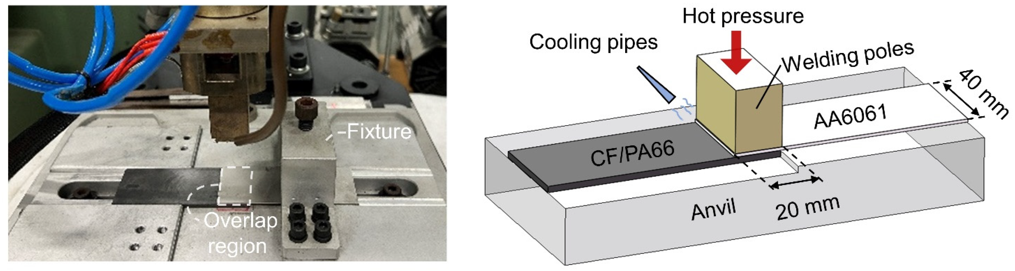
2.3. HPW of Textured AA6061 and CF/PA66

A HPW machine (NC-RY20, NICLE, Beijing, China), as shown in Figure 3, was utilized for the welding of the EJM-textured AA6061 sheets and CF/PA66 sheets. Before the welding process, a pre-welding drying treatment was carried out at 80 °C for 4 h to ensure the drying of CF/PA66. The overlap region of the AA6061 and CF/PA66 sheets in the HPW had an area of 40 × 20 mm2. Optimized parameters (i.e., welding temperature of 360 °C, welding pressure of 0.3 MPa, welding time of 12 s, and cooling time of 16 s) for the HPW of the same materials, as demonstrated in the literature [5], were applied in this study.

2.4. Characterization

A laser scanning confocal microscope (LEXT OLS4100, Olympus, Tokyo, Japan) was used for the morphological characterization and roughness measurement of EJM-textured AA6061 surfaces. Before the characterization of surface morphologies and roughness measurements, textured surfaces were ultrasonically cleaned with alcohol and then dried with high-pressure gas. As for roughness measurements, a typical area of 640 × 640 μm2 on the EJM-textured surface was selected as the test region. Measurements of roughness were conducted along 10 lines with an equal interval in the test region. The same measurement procedure was repeated twice on two textured surfaces generated with the same EJM parameters. The 20 measured roughness values were averaged to determine the roughness of the textured surface. Field-emission scanning electron microscopy (Sigma 300, ZEISS, Oberkochen, Germany) was utilized for the observation of surface texture morphologies. Tensile–shear tests were conducted using a universal testing machine (TSEOM-202203A, WANCE, Shenzhen, China) with a test speed of 2 mm/min to evaluate the AA6061-CF/PA66 joint performance. Each type of joint was subjected to four repeated tensile–shear tests. An optical microscope (AXIOCAM 208 COLOR, ZEISS, Oberkochen, Germany) was used to observe and analyze the microstructure of the joints. The interfaces of typical joints were characterized by Thermo Escalab 250Xi X-ray photoelectron spectroscopy (XPS) (Thermo Fisher Scientific, Waltham, MA, USA).

3. Results and Discussion

3.1. Parametric Effects on Surface Texture Generated by EJM

3.1.1. Effect of Current Density on Surface Roughness and Morphology

Figure 4 shows the correlation between the current density and roughness of the AA6061 surfaces textured by EJM. A smaller current density leads to increased surface roughness, irrespective of the jet translational speed employed. Surface morphologies at different current densities, with a translation speed of 0.5 mm/s, are shown in Figure 5. When a current density of 20 A/cm2 is applied, the surface is quite rough and exhibits lots of pores ranging in size from a few micrometers to one hundred micrometers. In addition, these multiscale pores distribute densely, causing a knife-like sharp edge of pores. As the current density increases to 50 A/cm2, the surface becomes relatively even. Multiscale pores still develop on the surface, but there are less large pores of a size of about one hundred micrometers. Increasing the current density further to 120 A/cm2 causes a smooth surface with only a few shallow large dimples. This relationship between current density and surface roughness, as well as morphology, in EJM can be explained by the change in dissolution kinetics with the increased current density [30]. At a small current density, the anodic workpiece surface stays in a fresh electrochemical environment due to the slow dissolution and rapid electrolyte flushing, causing the workpiece to dissolve in an active state. As such, the workpiece surface is non-homogeneously etched because of the different electrochemical characteristics of material microstructures and sub-microstructures. However, when the current density rises, a so-called supersaturated film forms on the workpiece surface since dissolved ions are generated massively and cannot be effectively removed. The anode kinetics in this scenario are mainly governed by mass transport rather than electrochemical charge transfer, which leads to a similar dissolving rate for different microstructures and generates a reasonably smooth machined surface. From the perspective of metal–CFRTP welding, the densely distributed multiscale pores with sharp edges created by EJM with low current densities are considered to be favorable for the mechanical interlocking effect at the joint interface.

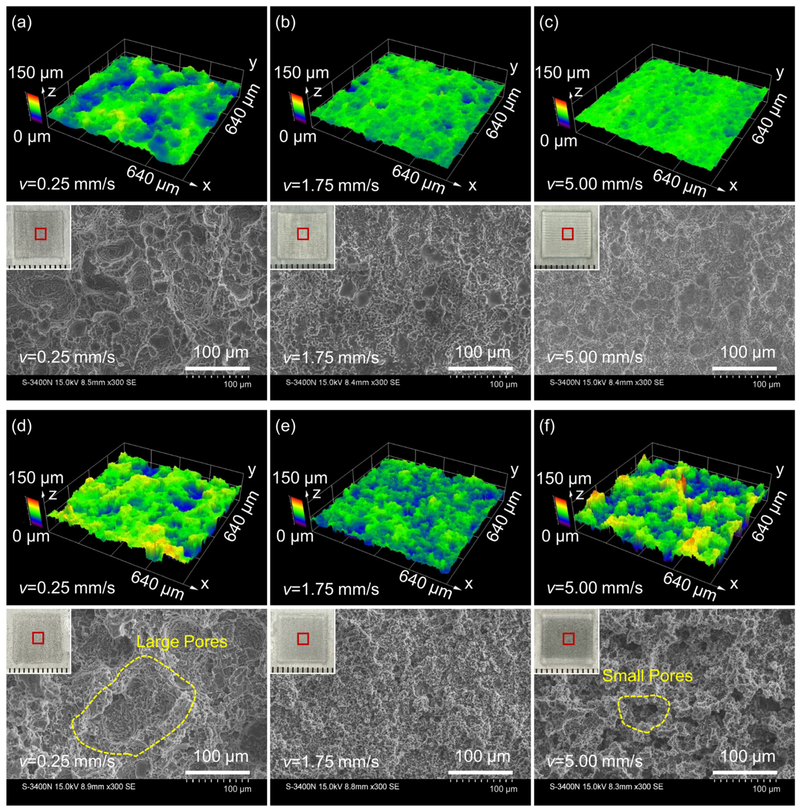
3.1.2. Effect of Jet Translational Speed on Surface Roughness and Morphology

The correlation between jet translational speed and the roughness of EJM-textured surfaces is depicted in Figure 6. At a current density of 50 A/cm2, as the translation speed rises, the roughness of textured surfaces decreases and eventually converges to a constant value of roughness. Figure 7a shows the typical surface morphologies at different jet translational speeds with a current density of 50 A/cm2. It is obvious that at a low translational speed of 0.25 mm/s, the surface is notably rough and features numerous pores at a width and depth of tens of micrometers, in addition to densely distributed pores a few micrometers in size. With the increase in translational speed, the number of pores in the tens of micrometers range reduces, resulting in a relatively even surface. This observed relationship between jet translational speed and surface roughness is attributed to the varied dwelling duration of the low current density surrounding the jet [30,31,32]. A Gaussian-type distribution of current density is created on the workpiece surface impinged by the jet in EJM. Hence, each given spot of the workpiece surface always eventually gets affected by a low current density when the jet translates. The faster translation of the jet leads to a shorter dwelling time of low current density, which, therefore, helps in weakening the material-microstructure-dependent etching induced by low current density. Meanwhile, at a higher current density of 300 A/cm2, the roughness is low and remains relatively constant irrespective of translational speed. This can be explained by considering that an excessively high machining current causes a significant increase in current density even at the periphery of the jet, thereby limiting the effect of material-microstructure-dependent etching even at a low jet translational speed.
Note that the roughness–speed curve at a current density of 20 A/cm2 exhibits a different tendency within the range of high jet translational speed from the abovementioned current densities. When the translational speed exceeds 1.75 mm/s, the surface roughness begins to noticeably increase and finally reaches a roughness comparable to that at a low translational speed. The reason for this behavior may be associated with the inhomogeneous breakdown of the oxide layer of a valve metal in EJM when using small current densities combined with a fast translational speed [32]. In each translation of the jet, the complete breaking down of the oxide layer requires sufficient imposed electric charge. At a fast translational speed, combined with a small current density, the oxide layer on AA6061 cannot be completely removed, and the remaining local oxide layer hinders the dissolution while other regions dissolve, which, thus, results in a considerably rough surface. As shown in Figure 7b, the surface roughness at a high translational speed of 5 mm/s is similar to that at a low one (0.25 mm/s), but the surface morphologies are different. This evidence also suggests a different etching behavior at fast translational speeds paired with small current densities. The surface at 5 mm/s contains numerous pores with a comparable depth to that at 0.25 mm/s, while the width of pores generated at 5 mm/s is smaller than that at 0.25 mm/s. Therefore, it is reasonable to anticipate that EJM-textured surfaces at 0.25 mm/s and 5 mm/s may have a distinct influence on the metal–CFRTP joint performance, even though they have a similar roughness.
Further, for the subsequent selection of typical textured surfaces for the HPW process, it is necessary to obtain the roughness of all textured surfaces generated by EJM, employing current densities from 20 to 300 A/cm2 and jet translational speeds from 0.25 to 5 mm/s. For this, additional EJM experiments are conducted to determine the comprehensive effects of current density and jet translational speed on the roughness of textured surfaces, as shown in Figure 8. As can be seen, three typical levels of roughness can be created on AA6061 by EJM.

3.2. Effect of Surface Texture Generated by EJM on AA6061-CF/PA66 HPW Joints

Based on the experimental results in Section 3.1, surface textures with various roughnesses and morphologies can be generated on AA6061 by EJM. For the welding of metal–CFRTP, higher roughness on metal surfaces generally leads to improved joint performance due to strong mechanical interlocking [33]. Accordingly, to investigate the impact of surface textures created by EJM on the performance of HPW AA6061/CFRTP joints, four typical surface textures with varying surface roughnesses and morphologies (designated as groups AS, AF, B, and C in Table 3) were prepared prior to the welding process. Note that the AS and AF groups have the same level of roughness but different morphologies of surface textures, as discussed in Section 3.1.2. Additionally, non-treated surfaces, labeled as group D, were also arranged in the HPW experiments for comparison.

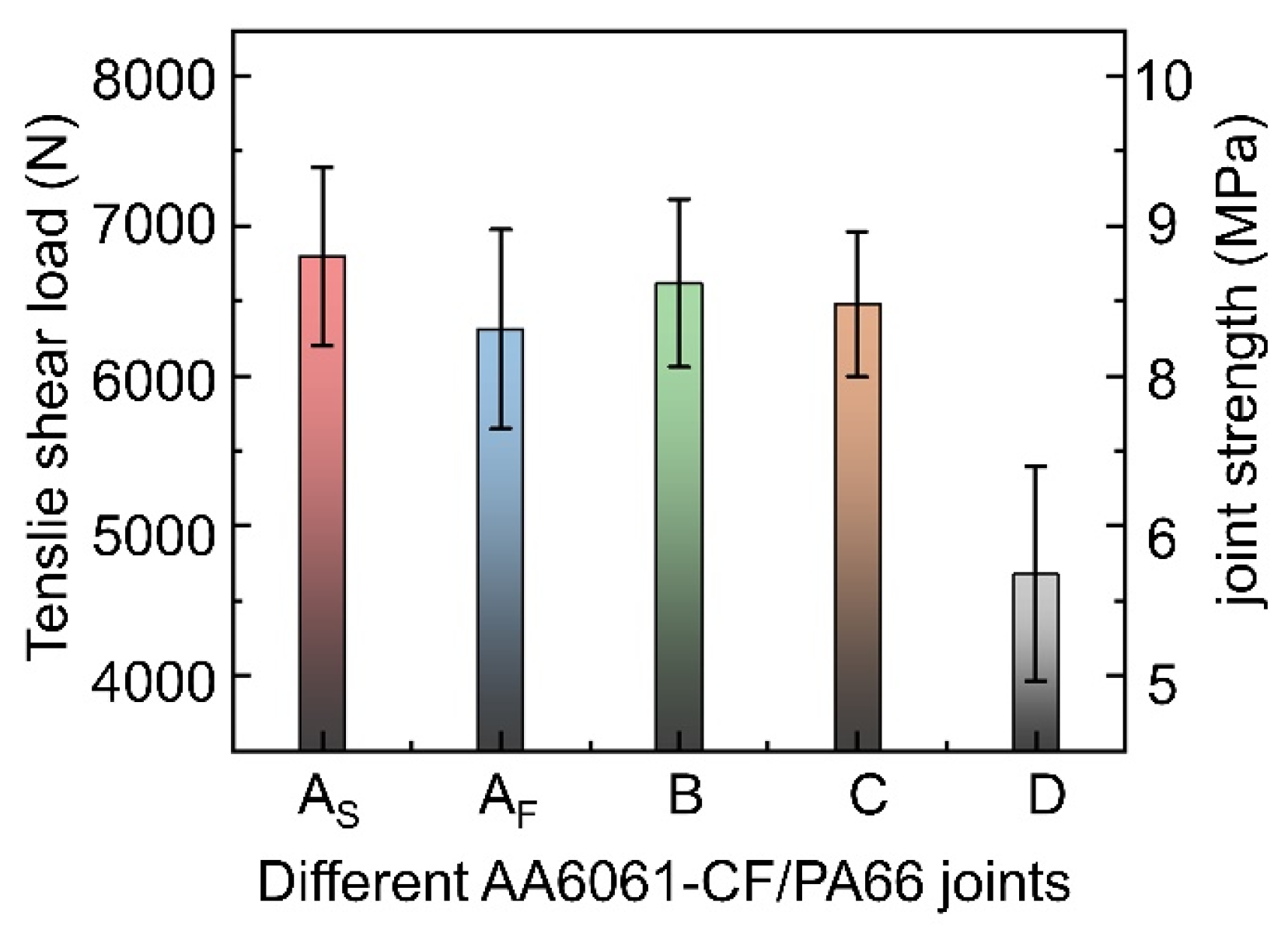
3.2.1. Mechanical Properties

Figure 10 displays the tensile–shear peak loads of the HPW joints with different AA6061 surface textures and non-treated AA6061 surfaces. In comparison to the joints with non-treated surfaces, the joint strength increases significantly with the EJM-textured surfaces on AA6061. Further, while comparing the joint strength of groups AS, B, and C, it is observed that the joint strength slightly increases with an increase in surface roughness. This may be explained by considering the interfacial area between the CFRTP and the metal, which is also an important factor affecting the joint strength in addition to the surface roughness [5,34]. Surfaces with large roughness have loosely distributed large pores, whereas surfaces with small roughness have densely distributed small pores. As a result, although groups AS, B, and C have different surface roughnesses, the interfacial area between the metal and CFRTP may be comparable. Hence, the shear strength may not differ much. Interestingly, the joints of group AF employ textured surfaces with an elevated level of roughness, but they have a comparatively lower strength. This might be associated with the different texture morphologies resulting from distinct etching mechanisms with a low current density and a fast translational speed, as explained in Section 3.1.2.

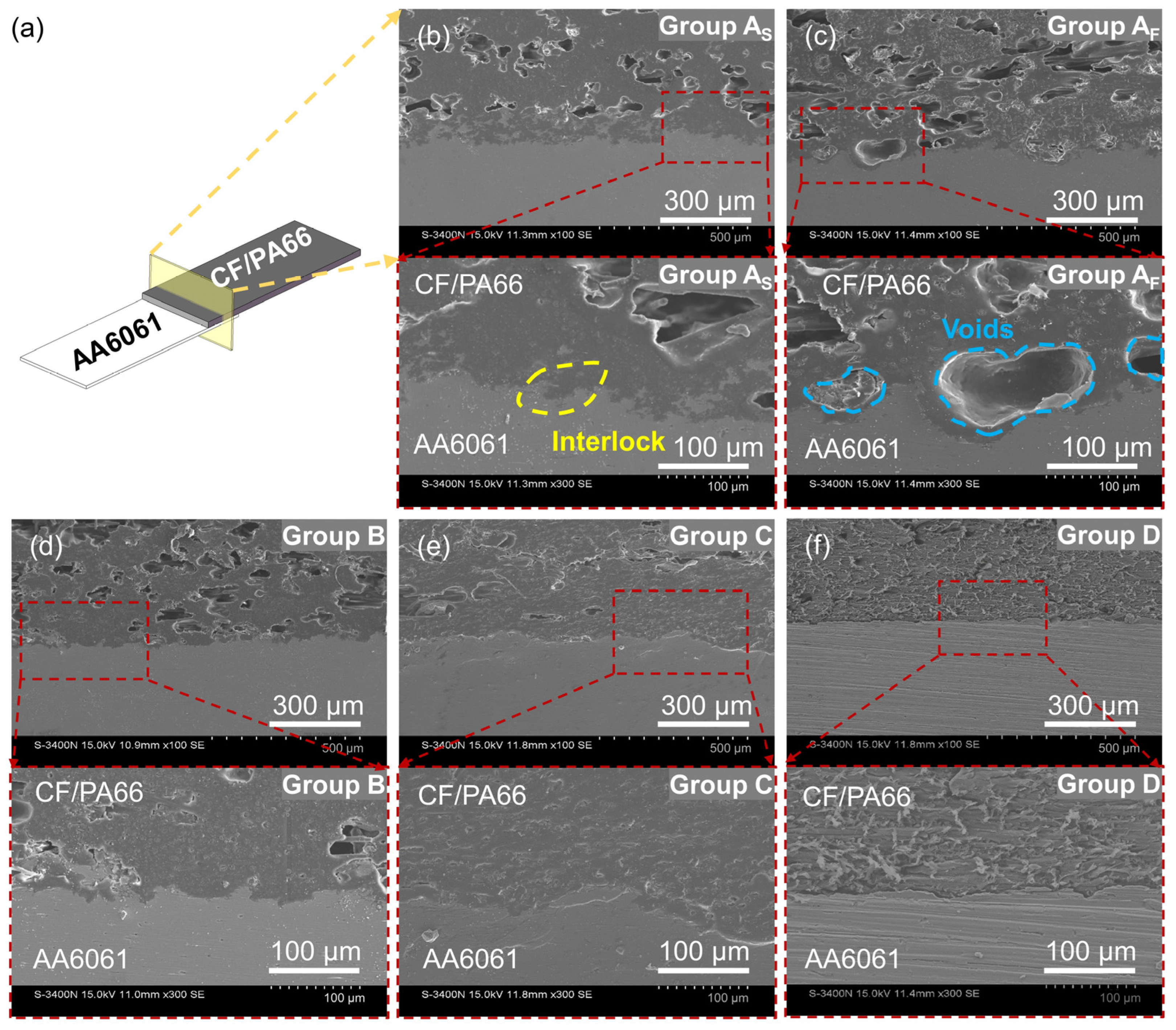
3.2.2. Interfacial Microstructure

The interfacial cross-sections of AA6061-CF/PA66 joints with varying surface treatments are shown in Figure 11. More apparent mechanical interlocking is found with EJM-textured surfaces compared to group D, which utilizes non-treated AA6061 surfaces. The resin fills the pores with sharp edges on the EJM-textured AA6061 surfaces, which allows the joints of groups AS, AF, B, and C to withstand greater shear force. Furthermore, in comparison with groups AS, B, and C, voids are observed at the joint interface of group AF. A probable reason for this is that the relatively small, deep pores on AF surfaces inhibit the effective infiltration of molten resin into these pores during the welding process. These voids cause a reduced bonding area and high stress concentration, leading to a comparably weak joint as a result. Among groups AS, B, and C, as the surface roughness rises, the increase in both the depth and width of pores on EJM-textured surfaces permits greater resin filling and enhanced mechanical interlocking.

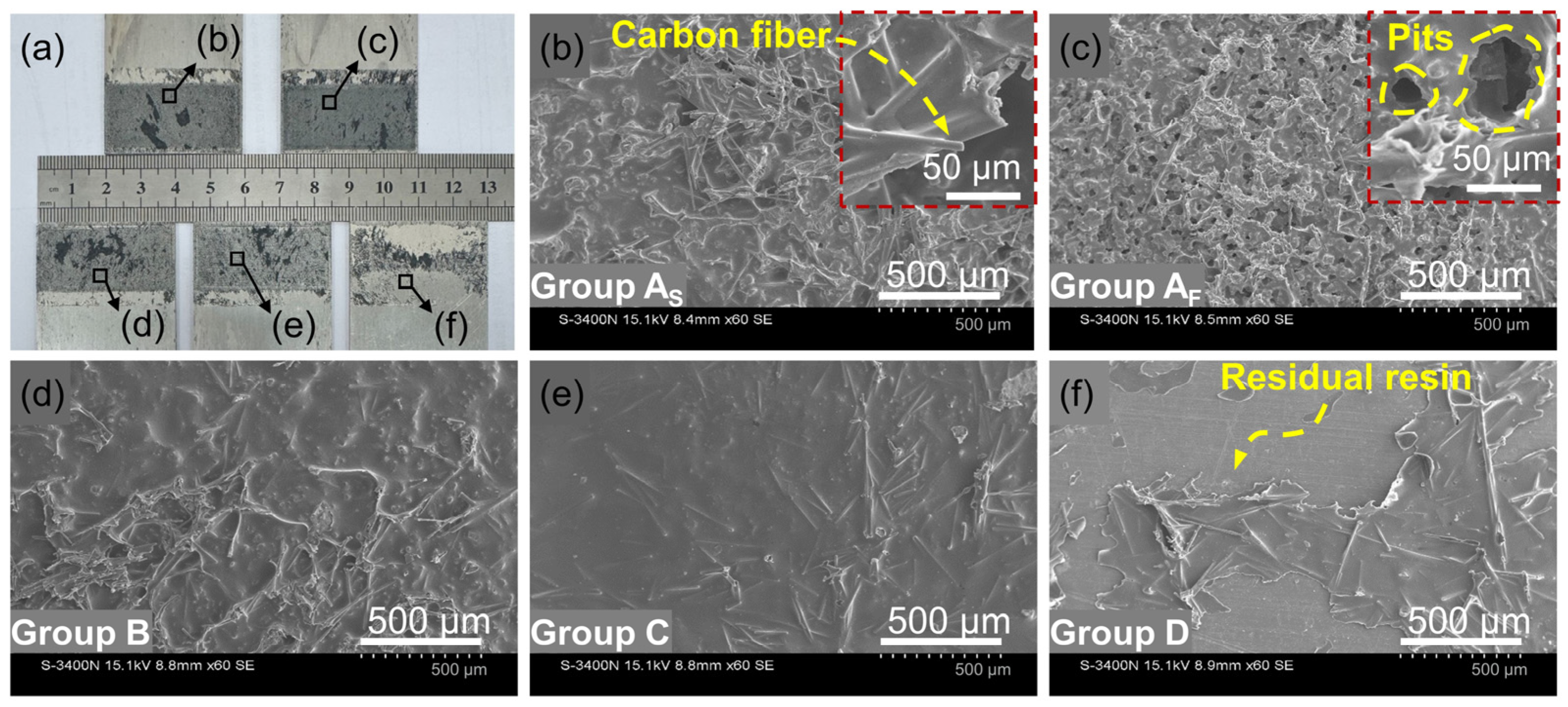
3.2.3. Fracture Morphology

Figure 12 depicts the typical morphologies of AA6061 surfaces after joint failure. Residual resin and carbon fibers are observed on the surfaces of AA6061 under all conditions. Nevertheless, group D exhibits a bare AA6061 surface in some locations, whereas the EJM-textured surfaces in groups AS, AF, B, and C are almost entirely covered with residual CF/PA66. Generally, the characteristics of the fracture morphology, as well as resin and carbon remaining on the metal surface, suggest a cohesive failure mode with a greater bonding strength between the metal and the CFRTP than the shear strength of the polymer matrix. In contrast, the bare metal surface indicates an adhesive failure mode, i.e., interfacial bond failure between the metal and the CFRTP. Hence, EJM texturing helps in enlarging the area of joints experiencing cohesive failure and considerably improves strength. Moreover, as shown in Figure 12b,d,e, the amount of carbon fibers remaining on the surfaces of groups AS, B, and C progressively diminishes in a sequential manner. When the carbon fibers are mechanically interlocked with the metal surface, they are peeled from the CFRTP matrix and remain on the metal surface after the joint failure. Accordingly, the mechanical interlocking effect and joint strength are reduced in the order of groups AS, B, and C. Additionally, in comparison with groups AS, B, and C, the residual CF/PA66 on the AA6061 surface of group AF exhibits numerous holes and minimal carbon fibers (Figure 12c). This further indicates that the molten resin and carbon fibers are not effectively filled into the textured-surface pores of group AF during the HPW process, and voids form at the joint interface, which, consequently, leads to poor mechanical interlocking and low joint strength, specifically measured at 7.8 MPa.

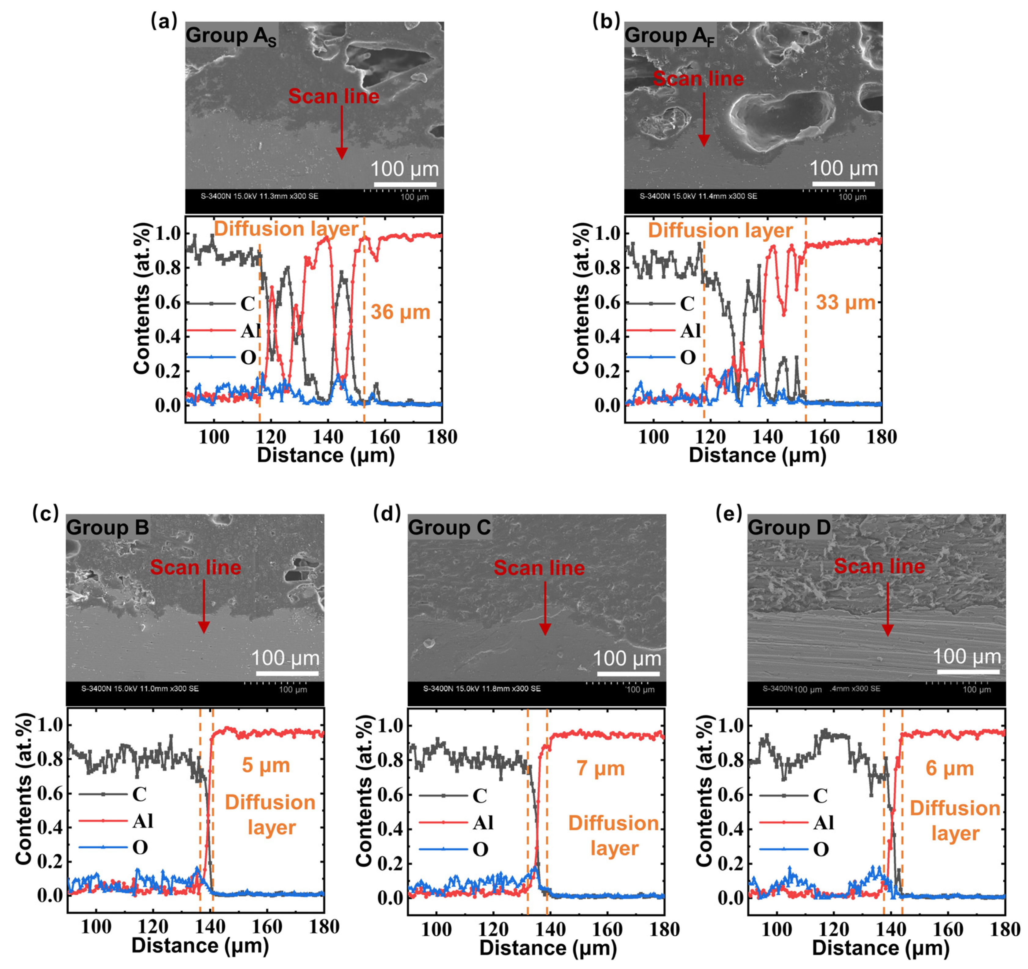
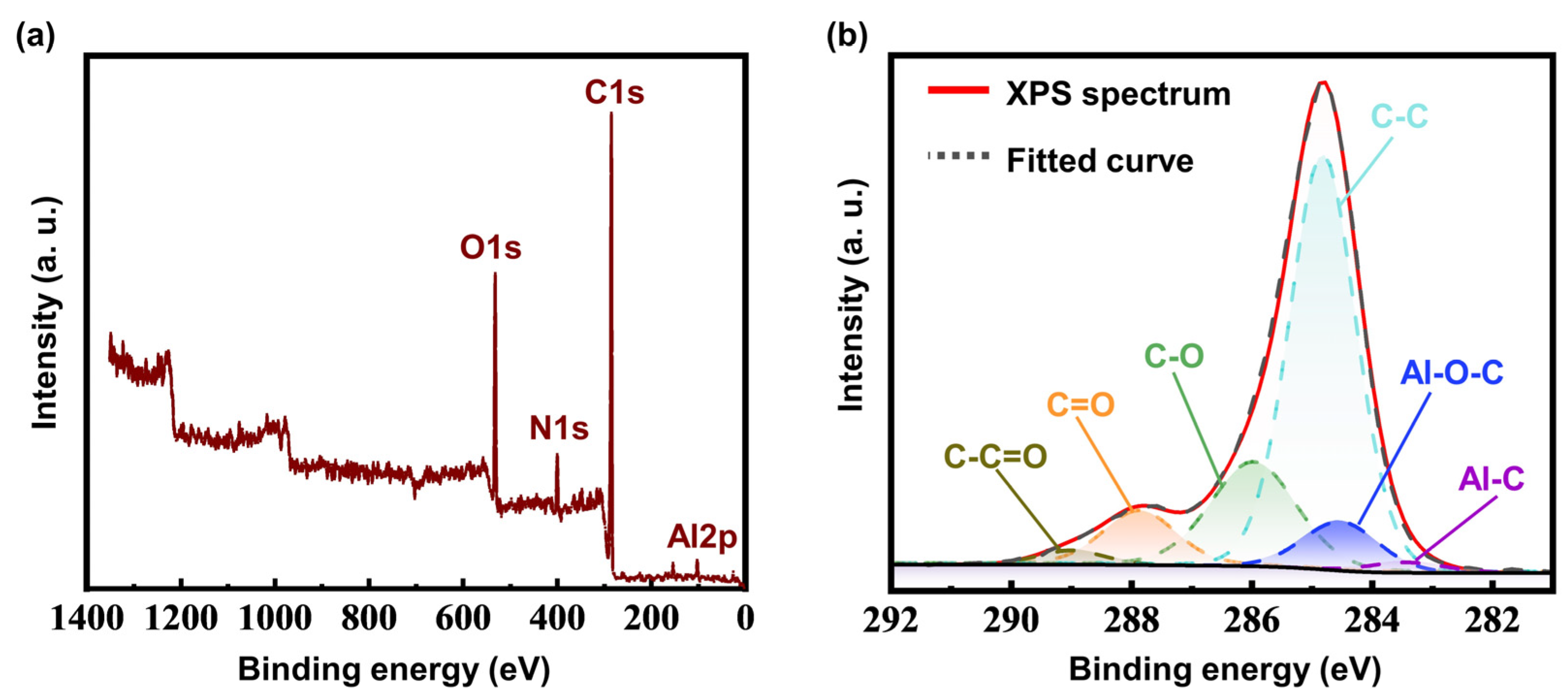
3.2.4. Interfacial Composition

Numerous studies have demonstrated that element diffusion occurs at the interface of metal–CFRTP joints, which is commonly regarded as evidence of chemical bonding [14]. For this reason, EDS line scanning is performed on the interface of different AA6061-CF/PA66 joints. Figure 13 demonstrates that, in all joints, the concentration of the C element decreases progressively from the CF/PA66 side to the AA6061 side, while the concentration of the Al element grows gradually. This indicates the existence of interfacial diffusion layers. Thus, chemical interactions, such as the formation of chemical bonds, may take place at the interface of CF/PA66 and AA6061 in addition to the mechanical interlock. Furthermore, it can be seen from Figure 13ab that there are clearly fluctuating concentration distributions at the interface. The reason for this phenomenon could be related to the complicatedly porous EJM-textured AA6061 surfaces of groups AS and AF. A partial sidewall of deep pores might appear above the base AA6061 at cross-sections, causing a rise in the Al element and a corresponding reduction in the C element at some locations of the interface. Therefore, the wide interface regions with fluctuating concentration distributions in groups AS and AF seem to be unrelated to enhanced chemical bonding, but demonstrate strong local mechanical interlocking.
For the further examination of the chemical bonds at the interface of the metal–CFRTP joints, a typical group of joints, AS, is analyzed by XPS. The XPS survey spectra are shown in Figure 14a. Al, C, O, and N elements are detected. In order to determine the bonding state of the C elements at the interface, high-resolution spectra of C1s are analyzed, as shown in Figure 14b. The Al-C and Al-O-C bonds are detected at binding energies of 283 eV and 284 eV, respectively. According to the literature [35], these bonds are developed at the interface of AA6061 and CF/PA66 during the welding process, providing support for the joining mechanism of chemical bonding.

4. Discussion

In this study, EJM is employed to generate surface texture to enhance the performance of AA6061-CF/PA66 HPW joints. The effects of the main parameters on the roughness and morphology of textured AA6061 surfaces in the EJM process are identified. In addition, the effects of EJM-textured surfaces on the strength of AA6061-CF/PA66 HPW joints are investigated. The following conclusions can be drawn from the present study.
(1) The EJM experimental results demonstrate that complex porous textures can be generated on AA6061 surfaces. The pores on the textured surfaces under suitable EJM conditions feature multiscale sizes ranging from a few micrometers to one hundred micrometers, and sharp edges.
(2) The investigation of EJM parametric effects shows that at a constant jet translational speed, decreasing the applied current density leads to an increase in both the size and number of pores produced on the textured AA6061 surfaces, resulting in a higher roughness. When a relatively high current density is employed, reducing the jet translational speed has a similar effect. However, at a relatively low current density (such as 20 A/cm2 in the present study), combined with a fast translational speed (such as >1.75 mm/s in the present study), further increasing the translational speed leads to the formation of deep pores and a significant increase in surface roughness.
(3) The results of the HPW experiments confirm that the strength of AA6061-CF/PA66 joints is significantly enhanced by EJM-textured AA6061 surfaces. Specifically, with suitable EJM parameters (such as a current density of 20 A/cm2 and a jet translational speed of 0.25 mm/s in the present work), the joint strength is increased by approximately 45.29%. The highest shear strength of the joint enhanced by EJM texturing reaches 8.49 MPa, while the joints without texturing have a shear strength of 5.84 MPa. The joint strength moderately improves as the roughness of EJM-textured AA6061 surfaces increases, with the exception of surfaces that are textured utilizing a combination of low current density and rapid translational speed.
(4) An improvement in the interfacial mechanical interlocking effect induced by EJM texturing is identified, contributing to the enhancement of joint strength. Furthermore, an observable diffusion layer, indicating the potential occurrence of chemical bonding, exists at the interface between AA6061 and CF/PA66.

Author Contributions

Conceptualization, W.L. and Y.L. (Yang Li); methodology, W.L.; validation, W.L. and Y.L. (Yan Luo); formal analysis, W.L. and Y.L. (Yan Luo); investigation, Y.L. (Yan Luo); resources, Y.L. (Yan Luo) and H.Z.; data curation, Y.L. (Yan Luo); writing—original draft preparation, W.L. and Y.L. (Yan Luo); writing—review and editing, W.L., Y.L. (Yang Li), Y.Z. and S.A.; visualization, Y.L. (Yan Luo); supervision, W.L. and Y.L. (Yang Li); project administration, W.L. and Y.L. (Yang Li); funding acquisition, W.L. All authors have read and agreed to the published version of the manuscript.

Funding

This research was funded by the Scientific Research Project of Tianjin Municipal Education Commission, grant number 2021KJ040.

Data Availability Statement

The data presented in this study are available on request.

Conflicts of Interest

The authors declare no conflicts of interest.

References

  1. Lambiase, F.; Scipioni, S.I.; Lee, C.J.; Ko, D.C.; Liu, F. A State-of-the-Art Review on Advanced Joining Processes for Metal-Composite and Metal-Polymer Hybrid Structures. Materials 2021, 14, 1890. [Google Scholar] [CrossRef] [PubMed]
  2. Almushaikeh, A.; Alaswad, S.; Alsuhybani, M. Manufacturing of carbon fiber reinforced thermoplastics and its recovery of carbon fiber: A review. Polym. Test. 2023, 122, 108029. [Google Scholar] [CrossRef]
  3. Liu, Z.G.; Li, Y.; Liu, Z.W.; Yang, Y.; Li, Y.; Luo, Z. Ultrasonic welding of metal to fiber-reinforced thermoplastic composites: A review. J. Manuf. Process. 2023, 85, 702–712. [Google Scholar] [CrossRef]
  4. Liu, Z.G.; Li, Y.; Liu, W.D.; Zhou, H.P.; Ao, S.S.; Luo, Z. Enhancing the ultrasonic plastic welding strength of Al/CFRTP joint via coated metal surface and structured composite surface. J. Manuf. Process. 2023, 108, 227–237. [Google Scholar] [CrossRef]
  5. Zhou, H.P.; Li, Y.; Liu, W.D.; Luo, Y.; Ao, S.S.; Luo, Z. Effect of Process Parameters on Joint Performance in Hot Pressure Welding of 6061 Aluminum Alloy to CF/PA66. Materials 2024, 17, 329. [Google Scholar] [CrossRef] [PubMed]
  6. Zhang, D.W.; Zhang, Q.; Fan, X.G.; Zhao, S.D. Review on Joining Process of Carbon Fiber-Reinforced Polymer and Metal: Methods and Joining Process. Rare Met. Mater. Eng. 2018, 47, 3689–3696. [Google Scholar]
  7. Faes, K.; Vermeersch, J.; Silva, R. Joining of Metal-Plastic Composites with Advanced Welding Processes. In Proceedings of the ASME 2021 16th International Manufacturing Science and Engineering Conference, Virtual, Online, 21–25 June 2021; V002T06A010; pp. 1–9. [Google Scholar]
  8. Li, Y.; Bu, H.C.; Yang, H.Y.; Liu, G.; Yao, J.A.; Zhan, X.H. Effect of laser heat input on the interface morphology during laser joining of CFRTP and 6061 aluminum alloy. J. Manuf. Process. 2020, 50, 366–379. [Google Scholar] [CrossRef]
  9. Jiao, J.; Xu, J.; Jing, C.; Cheng, X.; Wu, D.; Ru, H.; Zeng, K.; Sheng, L. Effect of Laser Micro-Texturing on Laser Joining of Carbon Fiber Reinforced Thermosetting Composites to TC4 Alloy. Materials 2022, 16, 270. [Google Scholar] [CrossRef] [PubMed]
  10. Nagatsuka, K.; Yoshida, S.; Tsuchiya, A.; Nakata, K. Direct joining of carbon-fiber-reinforced plastic to an aluminum alloy using friction lap joining. Compos. Part B Eng. 2015, 73, 82–88. [Google Scholar] [CrossRef]
  11. Guo, Y.; Zhao, H.B.; Ai, C.J.; Zhao, J.J.; Su, H.; Chen, J.; Zhao, G.Q. Parameter optimization of friction stir spot welded Al 6061 and CFRTP PA6 with surface treatment and interfacial adhesion. Thin-Walled Struct. 2024, 197, 111585. [Google Scholar] [CrossRef]
  12. Lionetto, F.; Mele, C.; Leo, P.; D’Ostuni, S.; Balle, F.; Maffezzoli, A. Ultrasonic spot welding of carbon fiber reinforced epoxy composites to aluminum: Mechanical and electrochemical characterization. Compos. Part B Eng. 2018, 144, 134–142. [Google Scholar] [CrossRef]
  13. Feistauer, E.E.; Santos, D.; Amancio, F. An investigation of the ultrasonic joining process parameters effect on the mechanical properties of metal-composite hybrid joints. Weld. World 2020, 64, 1481–1495. [Google Scholar] [CrossRef]
  14. Liu, Y.; Su, J.; Tan, C.W.; Feng, Z.; Zhang, H.; Wu, L.; Chen, B.; Song, X. Effect of laser texturing on mechanical strength and microstructural properties of hot-pressing joining of carbon fiber reinforced plastic to Ti6Al4V. J. Manuf. Process. 2021, 65, 30–41. [Google Scholar] [CrossRef]
  15. Li, W.; Geng, P.; Ma, N.; Chen, C. Effect of thermal-mechanical conditions on strength of silanized Al alloy/CFRTP hybrid joint made by thinning-controlled hot pressing. Mater. Today Commun. 2024, 38, 108507. [Google Scholar] [CrossRef]
  16. Zhang, X.Y.; Su, J.H.; Feng, Z.W.; Liu, H.R.; Xia, H.B.; Zhang, Z.Q.; Tan, C.W.; Chen, B.; Song, X.G. Effect of laser textured patterns on the interfacial characteristics and mechanical properties of 6061Al/GFRTP joints via hot-pressing. Thin-Walled Struct. 2023, 189, 110916. [Google Scholar] [CrossRef]
  17. Sandeep, R.; Natarajan, A. Advances in joining technologies for the innovation of 21st century lightweight aluminium-CFRP hybrid structures. Proc. Inst. Mech. Eng. Part E J. Process Mech. Eng. 2022, 236, 1239–1255. [Google Scholar] [CrossRef]
  18. Liu, Y.F.; Su, J.H.; Ma, G.L.; Han, X.H.; Tan, C.; Wu, L.J.; Chen, B.; Song, X.G. Effect of the laser texturing width on hot-pressing joining of AZ31B and CFRTP. Opt. Laser Technol. 2021, 143, 107350. [Google Scholar] [CrossRef]
  19. Abe, H.; Chung, J.C.; Mori, T.; Hosoi, A.; Jespersen, K.M.; Kawada, H. The effect of nanospike structures on direct bonding strength properties between aluminum and carbon fiber reinforced thermoplastics. Compos. Part B Eng. 2019, 172, 26–32. [Google Scholar] [CrossRef]
  20. Iwata, K.; Suzuki, A.; Kim, S.G.; Takata, N.; Kobashi, M. Enhancing the solid-state joinability of A5052 and CFRTP via an additively manufactured micro-structure. J. Mater. Process. Technol. 2022, 306, 117629. [Google Scholar] [CrossRef]
  21. Xia, H.B.; Yang, B.Y.; Su, J.H.; Liu, Y.F.; Su, X.; Wang, C.; Qiang, X.; Wu, T.; Tan, C.W. Improvement of laser welded TC4/CFRTP joint strength by combination of surface modification of MAO and laser texturing. Thin-Walled Struct. 2024, 196, 111409. [Google Scholar]
  22. Dong, H.G.; Tang, Z.Y.; Li, P.; Wu, B.S.; Hao, X.H.; Ma, C.Q. Friction stir spot welding of 5052 aluminum alloy to carbon fiber reinforced polyether ether ketone composites. Mater. Des. 2021, 201, 109495. [Google Scholar] [CrossRef]
  23. Speidel, A.; Bisterov, I.; Saxena, K.K.; Zubayr, M.; Reynaerts, D.; Natsu, W.; Clare, A.T. Electrochemical jet manufacturing technology: From fundamentals to application. Int. J. Mach. Tools Manuf. 2022, 180, 103931. [Google Scholar] [CrossRef]
  24. Yoneda, K.; Kunieda, M. Numerical analysis of cross sectional shape of micro-indents formed by the electrochemical jet machining. J. Jpn. Soc. Electr. Mach. Eng. 1995, 29, 1–8. [Google Scholar]
  25. Hackert-Oschätzchen, M.; Paul, R.; Martin, A.; Meichsner, G.; Lehnert, N.; Schubert, A. Study on the dynamic generation of the jet shape in jet electrochemical machining. J. Mater. Process. Technol. 2015, 223, 240–251. [Google Scholar] [CrossRef]
  26. Kunieda, M.; Mizugai, K.; Watanabe, S.; Shibuya, N.; Iwamoto, N. Electrochemical micromachining using flat electrolyte jet. CIRP Ann. 2011, 60, 251–254. [Google Scholar] [CrossRef]
  27. Lyu, X.; Kimura, F.; Zhao, Y.; Kunieda, M.; Kajihara, Y. Metal-polymer injection molded direct joining using electrolyte jet machining. In Proceedings of the 7th International Conference of Asian Society for Precision Engineering and Nanotechnology (ASPEN), Seoul, Republic of Korea, 14–17 November 2017. MFT–O–01. [Google Scholar]
  28. Lutey, A.H.A.; Jing, H.Y.; Romoli, L.; Kunieda, M. Electrolyte Jet Machining (EJM) of antibacterial surfaces. Precis. Eng. 2021, 70, 145–154. [Google Scholar] [CrossRef]
  29. Lutey, A.H.A.; Romoli, L.; Lee, J.; Kunieda, M. Tailoring microbial response to stainless steel surfaces via electrolyte jet machining and electrodeposition. J. Adv. Manuf. Technol. 2023, 129, 727–738. [Google Scholar] [CrossRef]
  30. Kawanaka, T.; Kunieda, M. Mirror-like finishing by electrolyte jet machining. CIRP Ann. 2015, 64, 237–240. [Google Scholar] [CrossRef]
  31. Kong, H.H.; Qu, N.S. Flat jet electrochemical milling of TC4 alloy with tailoring backward parallel flow. Chin. J. Aeronaut. 2023, 23, 574–592. [Google Scholar] [CrossRef]
  32. Liu, W.D.; Ao, S.S.; Li, Y.; Liu, Z.M.; Zhang, H.; Manladan, S.M.; Luo, Z.; Wang, Z.P. Effect of Anodic Behavior on Electrochemical Machining of TB6 Titanium Alloy. Electrochim. Acta 2017, 233, 190–200. [Google Scholar] [CrossRef]
  33. Feng, Z.W.; Zhao, H.Y.; Tan, C.W.; Zhang, X.Y.; Chen, B.; Song, X.G. Nanosecond laser ablation for improving the strength of CFRTP and aluminum alloy adhesively bonded joints. Compos. Struct. 2021, 274, 114369. [Google Scholar] [CrossRef]
  34. Yang, G.X.; Yang, T.; Yuan, W.H.; Du, Y. The influence of surface treatment on the tensile properties of carbon fiber-reinforced epoxy composites-bonded joints. Compos. Part B Eng. 2019, 160, 446–456. [Google Scholar] [CrossRef]
  35. Liu, F.C.; Dong, P.; Lu, W.; Sun, K. On formation of Al-O-C bonds at aluminum/polyamide joint interface. Appl. Surf. Sci. 2019, 466, 202–209. [Google Scholar] [CrossRef]
Figure 1. Principle of surface texturing by EJM using a film jet.
Jcs 08 00263 g001
Figure 2. Schematic of the EJM apparatus.
Jcs 08 00263 g002
Figure 3. Schematic of HPW of textured AA6061 and CF/PA66.
Jcs 08 00263 g003
Figure 4. Relationship between current density and AA6061 surface roughness in EJM.
Jcs 08 00263 g004
Figure 5. Typical morphologies of AA6061 surfaces textured by EJM at different current densities with a jet translation speed of 0.5 mm/s. The regions marked by red boxes on textured surfaces are for SEM examination.
Jcs 08 00263 g005
Figure 6. Relationship between jet translational speed and AA6061 surface roughness in EJM.
Jcs 08 00263 g006
Figure 7. Typical morphologies of AA6061 surfaces textured by EJM at different translational speeds with current densities of 50 A/cm2 and 20 A/cm2. (a) i = 50 A/cm2, v = 0.25 mm/s; (b) i = 50 A/cm2, v = 1.75 mm/s; (c) i = 50 A/cm2, v = 5 mm/s; (d) i = 20 A/cm2, v = 0.25 mm/s; (e) i = 20 A/cm2, v = 0.25 mm/s; (f) i = 20 A/cm2, v = 0.25 mm/s. The regions marked by red boxes on textured surfaces are for SEM examination.
Jcs 08 00263 g007
Figure 8. Dependence of AA6061 surface roughness textured by EJM on current density and jet translational speed.
Jcs 08 00263 g008
Figure 9. Morphologies of AA6061 surfaces textured by EJM with a translational speed of 3.5 mm/s and a current density of 80 A/cm2. The regions marked by red boxes on textured surfaces are for SEM examination.
Jcs 08 00263 g009
Figure 10. Joint strength with different surface textures and non-treated surface.
Jcs 08 00263 g010
Figure 11. SEM images of interfacial cross-sections of different joints. (a) Schematic of interfacial cross-sections of joints; (b) group AS; (c) group AF; (d) group B; (e) group C; (f) group D.
Jcs 08 00263 g011
Figure 12. AA6061 surface morphologies of different joints after failure. (a) Macroscopic view; (b) group AS; (c) group AF; (d) group B; (e) group C; (f) group D. The regions for SEM examination are marked by black boxes.
Jcs 08 00263 g012
Figure 13. EDS line scanning results at the interfaces of different joints. (a) Group AS; (b) group AF; (c) group B; (d) group C; (e) group D.
Jcs 08 00263 g013
Figure 14. XPS results for the joint interface of group AS. (a) Survey spectrum; (b) high-resolution spectra of C1s.
Jcs 08 00263 g014
Table 1. Main physical properties of AA6061 and CF/PA66.
MaterialElongation Melting
Point
Solid-Phase Line TemperatureLiquid-Phase Line TemperatureElasticity
Modulus
Tensile
Strength
AA606112.5%-582 °C650 °C68.7 GPa311 MPa
CF/PA661.4%260 °C--29.5 GPa355 MPa
Table 2. Experimental parameters for surface texturing by EJM.
ParametersValue
Electrolyte20 wt.% aq. NaCl
Slit nozzle length (l)38 (mm)
Slit nozzle width (b)0.1 (mm)
Flow velocity (f)4.28 (m/s)
Electric charge (Q)240 (C/cm2)
Current density (i)20, 50, 80, 120, 200, 300 (A/cm2)
Jet translational speed (v)0.25, 0.75, 1.25, 1.75, 3.5, 5 (mm/s)
Table 3. EJM-textured AA6061 surfaces for HPW experiments.
GroupsEJM ParametersSurface Roughness RaSurface Morphology
ASi = 20 A/cm2; v = 0.25 mm/s13 μmShown in Figure 7d
AFi = 20 A/cm2; v = 5 mm/s13 μmShown in Figure 7f
Bi = 50 A/cm2; v = 0.25 mm/s8 μmShown in Figure 7a
Ci = 80 A/cm2; v = 3.5 mm/s4 μmShown in Figure 9
DNo treatment1 μm
Disclaimer/Publisher’s Note: The statements, opinions and data contained in all publications are solely those of the individual author(s) and contributor(s) and not of MDPI and/or the editor(s). MDPI and/or the editor(s) disclaim responsibility for any injury to people or property resulting from any ideas, methods, instructions or products referred to in the content.

