Article

Post-Forming of Carbon Fibre-Reinforced PEEK Thermoplastic Tubular Structures

Research School of Physics, Australian National University, Canberra, ACT 2600, Australia
*
Author to whom correspondence should be addressed.
J. Compos. Sci. 2024, 8(9), 335; https://doi.org/10.3390/jcs8090335
Submission received: 15 July 2024 / Revised: 16 August 2024 / Accepted: 20 August 2024 / Published: 23 August 2024
(This article belongs to the Section Composites Manufacturing and Processing)

Abstract

:
This paper presents a post-forming technique utilising both induction heating and rotary draw bending (RDB) for carbon fibre-reinforced polyetherentherketone (CF/PEEK) tubular structures. Existing post-forming techniques are unable to form CF/PEEK tubes due to the lack of a suitable mandrel material to provide internal support to the tube while withstanding high heat from melting the PEEK matrix during forming. This is addressed by using a steel spring mandrel in the tube induction heating process. In this study, four sets of [±60°]4 CF/PEEK tubes were formed using an induction heater-incorporated RDB setup into 45°, 90°, 135°, and 180° bends with a bending ratio of 2. Optical characterisation was performed to analyse tube fibre angle changes. A post-forming fibre angle prediction model previously derived for CF/polyamide 6 tubes was validated for its application in predicting fibre angle changes for CF/PEEK tubes by comparing the prediction with the characterised results.

1. Introduction

Composites with thermoplastic matrices provide high-performance manufacturing in industries such as automotive, aerospace, sport, and energy as a high-stiffness, high-strength, lightweight, and thermo-formable material solution [1,2,3]. When applied in the form of tubular structures with circular cross-sections, thermoplastic composite tubes display high energy absorption capability with high flexural and torsional rigidities with respect to weight, making them ideal for structural applications [4,5,6].
Polyetherentherketone (PEEK) is a type of thermoplastic polymer with excellent chemical resistance and high modulus of elasticity [7,8,9]. As compared to other thermoplastic matrix systems, PEEK is more suited for high-temperature applications due to its high melting temperature of 343 °C [10]. With these advantages, carbon fibre-reinforced PEEK (CF/PEEK) composites have been widely used for heavy-duty applications in the high-performance industries [11,12]. In the automotive industry for example, CF/PEEK tubes are used as drive shafts for high-performance cars [13].
The manufacturing of thermoplastic tubes has developed from manual to automated placement with improved efficiency and component sizes [14]. Automated placement processes such as laser-assisted thermoplastic automated tape placement (TP-ATP) enable rapid manufacturing of thermoplastic tubes using pre-impregnated (prepreg) tapes [15,16]. During the TP-ATP process, a laser beam is applied to locally melt the matrix layer of a prepreg tape to join them layer-wise around a winding mandrel, allowing for the precise control of the number of plies and winding angle per ply [17,18,19]. As a thermoplastic matrix, PEEK opens up the possibility for CF/PEEK tubes to be post-formed into new geometries upon reheating its matrix into a soft and formable state [15]. While tight or continuous bends cannot be wound directly by TP-ATP due to the possible interference of the placement head with the mandrel, tape tension during winding, and complex coordinated motion requirements [20], curvatures can be produced via post-forming of straight tubes made by TP-ATP [21,22].
Post-forming of thermoplastic tubes enables a rapid production of customised curvatures from batch-produced straight tubes [23]. This allows for more possibilities in the design of CF/PEEK parts to suit a wider range of applications. In this case, structures with complex geometries and bends such as spaceframes and vehicle chassis reinforcements can be manufactured using CF/PEEK tubes efficiently without joints at the bends. A main existing post-forming technique involves the use of rotary draw bending (RDB) at elevated temperature, where forming trials have been conducted using carbon fibre-reinforced polyamide 6 (CF/PA6) tubes [23]. Using RDB, tube curvatures can be rapidly produced and customised by adjusting the bending angle without changing the bending die, hence allowing for design customisation at reduced tooling cost [24]. In previous studies, straight CF/PA6 tubes were heated to their matrix melting temperature of 220 °C before forming using either an oven or infrared heaters [20,23]. A soft silicone mandrel was used to provide internal support for maintaining tube ovality during the post-forming of CF/PA6 tubes [20,23,25]. However, the lower melting point of the silicone mandrel than that of the PEEK matrix can lead to melting of the mandrel prior to forming. As a result, the use of a silicone mandrel may be inappropriate for post-forming CF/PEEK tubes as tubes may experience undesired failures and deformation during forming due to insufficient internal support by the melted mandrel.
To enable rapid post-forming of CF/PEEK tubes, this paper presents a post-forming technique utilising induction heating and RDB akin to post-forming of CF/PA6 tubes. Instead of a silicone mandrel with a low melting point, a steel spring mandrel is used for its stiffness, bendable design, ferromagnetic properties, and high melting point [26,27,28].
In this study, CF/PEEK tube post-forming experiments were conducted to demonstrate the forming technique. Four sets of [±60°]₄ CF/PEEK tubes were post-formed to bend angles 45°, 90°, 135°, and 180°, respectively, using an induction heater-incorporated bespoke RDB setup. A long-wave infrared (LWIR) camera was used to record tube surface temperature profiles during post-forming and control heating. Optical measurements using a Micro-Vu Vertex automated precision measurement system were conducted to characterise changes in fibre angles of tube bending zones before and after post-forming. Fibre angles measured before forming were processed using the formerly derived fibre angle prediction model for CF/PA6 tubes. The predictions were evaluated against fibre angles measured after forming to validate the fibre angle prediction model in the post-forming of CF/PEEK tubes.

2. Materials and Methods

2.1. CF/PEEK Tube Manufacture

Straight [±60°]4 CF/PEEK tubes were manufactured at the Australian National University (Canberra, Australia) via TP-ATP following the parameters used in [23]. Twelve-millimetre-wide Suprem™ T 55% C10003/PK10002 CF/PEEK tapes (Celanese Corporation, Irving, TX, USA) with a fibre volume content of 55% were wound onto a 20 mm diameter solid chromed steel mandrel at a process temperature of 400 °C and a placement rate of 12 m/min with a consolidation force of 300 N. A conventional helical filament winding pattern with three circuits (p = 3) and a shift parameter of one (Nₛ = 1) per ±60° layer pair as defined in [29] was used to manufacture the straight CF/PEEK tubes. This led to the manufactured tubes with a winding angle of approximately ±53° for their innermost plies, increasing gradually to ±57° for their outermost ply for eight plies. The manufactured tubes were measured to have an average inner diameter (di) and outer diameter (do) of 20 mm and 22.6 mm, respectively, resulting in an average wall thickness of 1.3 mm per tube.
The total length of each tube consisted of its initial bending zone length (l0), a 60 mm clamping length, and a 40 mm hanging length on each end of its bending zone, respectively. l0 of a tube can be determined by multiplying the bending diameter (2rb) with the ratio between the tube bending angle (α) and 360°.
l 0 = 2 r b π α 360 °

2.2. Post-Forming Experiments

2.2.1. Rotary Draw Bender Setup

RDB post-forming experiments were conducted using a setup containing a bespoke rotary draw bender and an Across International IH8A induction heater. The bender is similar in design to a traditional bender for metallic tubing with the exception of the wiper die, which is redundant in this case due to the direction of force application. The dies are made from aluminium to withstand heat from the tube, and the main bending die has a cut-out to accommodate the induction coil. The pressure die is fixed in place to restrict unwanted displacement of the unbent tube section during forming.
The induction heater has a maximum output power of 8 kW and an output frequency range between 30 and 80 kHz. In this study, the output current of the heater was set to its minimum of 105 A to reduce its effect on other aluminium bender parts following [30]. Attached to the heater is a three-turn copper induction coil. The coil has a total span of 25 mm, an internal diameter of 55 mm, and an external diameter of 67 mm to enable induction heating of the work piece within the coil. The coil was positioned as shown in Figure 1, where it was concentric to the straight CF/PEEK tube with its centre aligned with the start of the tube bending zone.
A steel Clipsal 266MD25 medium-duty conduit (Clipsal by Schneider, Macquarie Park, Australia) bending spring was used as the bending mandrel. The spring mandrel was made of a rigid material in a bendable design, which provided adequate support to maintain tube ovality during bending [28]. The mandrel was also ferromagnetic and highly responsive to induction heating, which catalysed the tube heating process [26,27]. The mandrel had an average coil diameter of 19.5 mm, which was 0.5 mm smaller than the inner diameter of the straight tube to allow easy loading and unloading of the mandrel in the tube. When bent with the tube during forming, the coil diameter of the mandrel remained constant to provide internal support to the tube. As the mandrel was more responsive to induction heating than the tube, the heating rate of the mandrel was higher than that of the tube in the induction coil [30]. Therefore, when a tube was heated with the steel mandrel inserted, a shorter tube heating time was possible by the joint effect of heat transfer from the heated mandrel to the tube and induction heating of the tube itself [30].

2.2.2. Post-Forming Parameters

In this study, four sets of three identical [±60°]4 CF/PEEK tubes each were post-formed to bending angles of 45°, 90°, 135°, and 180°, respectively, in the RDB setup with a bending radius of 46 mm and a bending ratio of 2. The bending ratio is defined as the ratio between the radius of the main bending die (the bend formed) and the diameter of the tube [25]. For dimensions of the tubes used in this study, 2 is the smallest bending ratio for the tubes to be post-formed without failures, as calculated from the forming limit model derived in [31].
The CF/PEEK tapes have a melting point at 343 °C according to the material datasheet. Partial melting of the PEEK matrix allows for fibre relocation and reorientation to create curvatures [20]. Heating trials were conducted prior to the post-forming experiments to determine the formable temperature of the CF/PEEK tubes. Using the RDB setup, straight CF/PEEK tubes were heated from 300 °C to 360 °C at 5 °C intervals using the induction heater. Bending was attempted at each heating temperature. Tubes formed at between 335 °C and 340 °C demonstrated smooth surface finish without visible wrinkling or delamination, whereas tubes formed at temperatures below 335 °C showed wrinkling due to restricted fibre movements in an insufficiently melted matrix and tubes formed at temperatures above 340 °C experienced delamination due to overheating. Considering possible heat loss during the forming process, this study adopted 340 °C as the formable temperature of CF/PEEK tubes for the post-forming experiments.

2.2.3. Post-Forming Method and Experimental Procedure

The post-forming process of CF/PEEK tubes is performed via two steps, namely heating and bending, as shown in Figure 1.
The heating process first took place after the tube containing the mandrel was loaded into the RDB setup. The mandrel was divided into numerous sections to be heated accordingly. The divided mandrel sections were of identical lengths corresponding to the span of the induction coil represented by sections A and B in Figure 1a,b. Based on the bending ratio used in this study, each preheat mandrel section corresponded to 22.5° of the tube bending angle (i.e., two preheat mandrel sections for a tube with 45° bend). To perform localised heating of the tube, section A started at 70 mm from the start of the spring to avoid direct heating of the clamping length of the tube as shown in Figure 1a. A preheating process was adopted to ensure relatively even heating along the tube bending zone for a continuous forming process to produce bends with a smooth and consistent finish.
In the preheating process, section A was first heated until the surface temperature of the tube area inside the coil stabilised at 260 °C, which took an average of 60 s in this study. It was then further heated to 300 °C, taking approximately 15 s on average. While keeping the tube clamped, the mandrel was then moved to have section B positioned inside the coil as shown in Figure 1b and the heating process was repeated. For the subsequent tube sections after section A, preheating of each section took approximately 45 s. This was shorter than the preheating time for section A due to heat transfer from the preheated sections. Stepped heating was implemented to prevent overheating of the tube as temperature measurements were taken on the outer surface of the tube, meaning that the inner surface temperature of the tube could be higher. The preheating process was repeated for all mandrel sections necessary for the desired bending angle. For the final section, it was further heated for approximately 15 s until the tube surface temperature stabilised at 340 °C to enable forming.
Once the final section was heated, the bending die was rotated to the desired bending angle as shown in Figure 1d. The bending die was turned at a uniform bending rate of approximately 3°/s with the induction heater turned on to maintain formable temperature of the tube throughout the bending process. Upon bending, the heater was turned off and the post-formed tube was held in position during the re-solidification of the matrix until tube bending zone surface temperature dropped below 200 °C to minimise the effect of spring-back.

2.3. Forming Behaviour Characterisation

2.3.1. Measurement Procedures of Fibre Angles

Tube fibre angles before and after forming were measured using a Micro-Vu Vertex automated precision measurement system (Micro-Vu, Windsor, CA, USA) following [23]. The Micro-Vu system is a type of coordinate measuring machine that uses optical sensors to accurately measure an object. A pattern of light is projected onto the object being measured by the system to capture the image of the deformed object pattern. Advanced software algorithms were used by the system to process and analyse the captured image, enabling precision measurements including that of CF/PEEK tube fibre angles. Measurements of fibre angles were taken in even intervals at tube intrados and extrados where the most significant changes were expected. Fibre angles measured before forming were processed using the previously derived post-forming fibre angle prediction model from [23] to obtain predictions of their corresponding post-formed fibre angles. These predictions are compared with the fibre angles measured after forming to identify potential discrepancies.

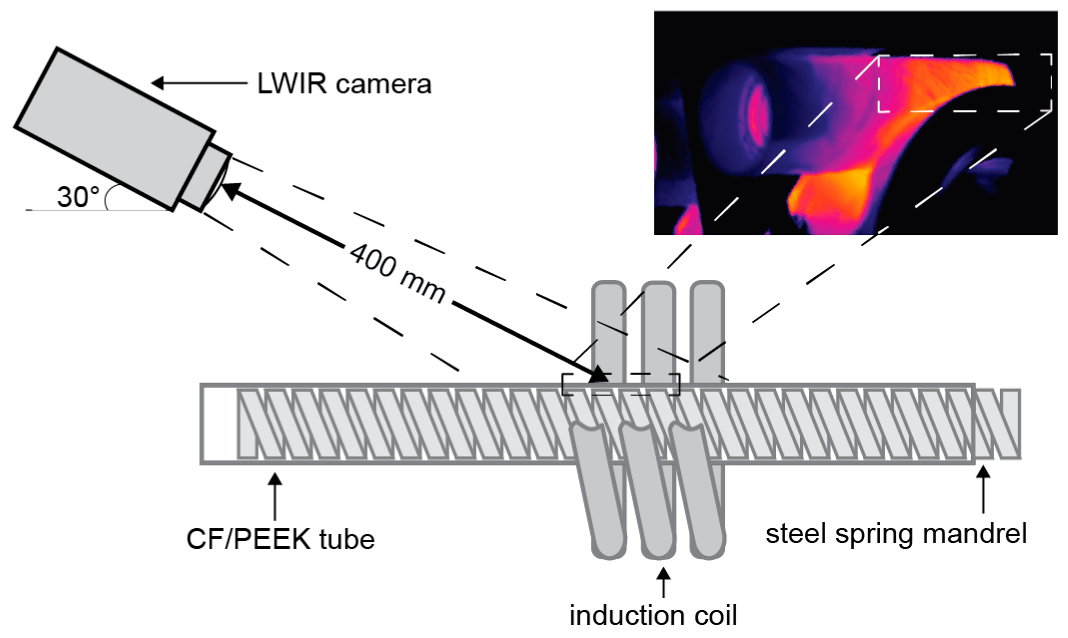
2.3.2. Measurement Procedures of Tube Temperature

Temperature measurements during the post-forming experiments were taken from the outer surface of the tube using a Gobi-640-Gige LWIR camera (Xenics, Leuven, Belgium). The camera was placed 400 mm from the measurement point as shown in Figure 2. Preliminary temperature measurement trials were conducted to determine emissivity of the CF/PEEK tubes. For this purpose, an 5SC-TT-K-40-36 fine wire K-type thermocouple (Omega Engineering, Norwalk, CT, USA) was attached to the outer surface of a stationary CF/PEEK tube placed inside the induction coil. The tube was heated and its temperature was measured by both the LWIR camera and the thermocouple. The thermocouple measurements were recorded by a cDAQ-9188 data logger (National Instruments, Austin, TX, USA). Emissivity of the CF/PEEK tube was derived from dividing the temperature measured by the LWIR camera by the temperature measured by the thermocouple. The average emissivity of the CF/PEEK tubes was derived to be 0.9 and was used to calibrate the LWIR camera for the post-forming experiments.

3. Results

The presented post-forming technique was able to rapidly produce bent CF/PEEK tubes. For instance, heating and bending of a tube to 45° took approximately 135 s. No surface defects were observed from the post-formed tubes as evident from the examples shown in Figure 3. The tubes formed with a bending ratio of 2 showed a maximum local fibre orientation increase by 14.54° on the intrados and decrease by 15.60° on the extrados. Bent CF/PEEK tubes with no visible surface defects were produced as reflected from examples in Figure 3. However, it was found that as tube bending angles increased, it was more difficult to remove the spring mandrel from the formed tubes. The mandrel removal process involved twisting of the mandrel out from a formed tube. Snapping of the mandrel occurred during its removal from a tube formed to 180° even though tube geometry and surface finish were not affected.
A variation of ±2° was found in the initial fibre angles measured, resulting in slight variations in the predictions. The post-formed fibre angle measurements and predictions were normalised with respect to the initial fibre angle measurements to show potential discrepancies.

4. Discussion

4.1. Post-Forming Tube Temperature

During the forming process, temperature profiles of the tubes were relatively even as evident from a small temperature gradient of ±1° recorded on the outer tube surface inside the coil by the LWIR camera. Uniform heating of the tubes enabled even softening of the matrix, and hence consistent fibre movements within tube bending zones. This was reflected from the optical analysis of the post-formed tubes, where no defect was found on the surfaces of the tubes. From the fibre angle analysis, the close agreement between the measurements and the predictions shown in Figure 4 also reflected even heating of the tubes during post-forming.

4.2. Post-Forming Tube Fibre Angle Change

As shown in Figure 4, post-formed tube fibre angle predictions fell within the standard deviations of post-formed fibre angle measurements in general for tubes formed to all four bending angles. In particular, the closest agreements were found at the start and the end of the bending zones. The average measured post-formed fibre angles at the start of the bending zone differed from the predictions by 1.27%, 0.05%, 0.57%, and 0.89% for tubes formed to 45°, 90°, 135°, and 180°, respectively. The average measured post-formed fibre angles at the end of the bending zone differed from the predictions by 1.18%, 1.17%, 0.48%, and 0.41% for tubes formed to 45°, 90°, 135°, and 180°, respectively.
These close agreements between the predictions and the measurements were due to localised heating performed on tube bending zones only. As tube bending zones were heated to the formable temperature of 340 °C while the rest of the tubes were insufficiently heated, fibre movements were constrained within the softened bending zone matrices. Since the induction heating sections were precisely controlled by the span of the coil, the start and the end of tube bending zones were expected to have minimum fibre angle changes as reflected from the results in Figure 4.
Additionally, the differences between fibre angle measurements and predictions at tube intrados and extrados were similar as shown in Table 1. This similarity suggested even fibre movements throughout the tube, hence validating the effectiveness and consistency of internal support provided by the spring mandrel and tube heating using the induction coil.
With the close agreement between the measured and predicted fibre angles, the post-forming fibre angle prediction model was validated for its application in the post-forming of CF/PEEK tubes.

5. Conclusions

In this study, a post-forming technique for CF/PEEK tubes was presented and the fibre angle changes in the tubes were evaluated against the previously derived post-forming fibre angle prediction model. For this purpose, post-forming experiments were conducted using [±60°]4 CF/PEEK tubes with a bending ratio of 2. The post-forming technique utilised induction heating and RDB, and a steel spring mandrel was used. Induction heating allowed uniform heating of a localised tube section to evenly melt the PEEK matrix to enable fibre movements. RDB, on the other hand, enabled quick and efficient bending of tubes with a softened matrix into various bending angles of the same bending ratio without changing the bending dies.
In the forming experiments, stepped preheating was conducted on the spring mandrel inserted in the tubes using an induction coil. The designed bending zone of a straight CF/PEEK tube was locally heated by the joint effect of heat transfer from the preheated mandrel as well as induction heating of the tube itself to its formable temperature of 340 °C. At this temperature, the PEEK matrix was softened to enable fibre relocation and reorientation within the bending zone to enable forming. As tube bending zones were locally heated to the formable temperature while the rest of the tubes were below this temperature, undesired tube geometrical distortions due to fibre angle movements beyond tube bending zones were minimised. The heated tube was then formed to the designed bending angle by turning the main bending die of the RDB setup at a uniform rate of 3°/s while maintaining the formable temperature of the tube bending zone.
The presented post-forming technique was found to be capable of rapidly producing high-quality bends with low geometrical distortions. As a rigid material in a bendable coil spring design, the steel spring mandrel was found to be capable of providing internal support to the tubes during forming at high temperature, hence maintaining ovality of the tubes. Sufficient support to the tubes provided by the spring mandrel in addition to the localised heating of tube bending zones only contributed to successful forming of CF/PEEK tubes as evident from the comparison between measured and predicted fibre angles as follows:
  • Fibre angles at the start and end of tube bending zones were unchanged for all four bending angles during forming, indicating the absence of fibre movements beyond tube bending zones;
  • The predicted fibre angles were within the standard deviations of the measurements at both tube intrados and extrados for tubes formed to all four bending angles.
The agreement between the model predictions and the measured fibre angles after forming also validated the post-forming fibre angle prediction model for CF/PEEK tubes.
Future work will include further improvements in efficiency of forming by increasing the forming rate while maintaining consistency and quality of the bends. Optimisation in mandrel design may also be investigated to enable easier unloading from a bent tube. In this study, only [±60°]4 CF/PEEK tubes with the bending ratio of 2 were analysed. Post-forming of CF/PEEK tubes with different initial fibre angle configurations and varying bending ratios may be conducted to further validate and refine the forming technique presented. Additional investigations on the effect of changing fibre orientations upon post-forming on the mechanical properties of the tubes may also be made.

Author Contributions

Conceptualization, M.L., C.S.-G. and P.C.; methodology, M.L. and C.S.-G.; software, M.L.; validation, M.L., C.S.-G. and P.C.; formal analysis, M.L.; investigation, M.L.; resources, C.S.-G. and P.C.; data curation, M.L.; writing—original draft preparation, M.L.; writing—review and editing, C.S.-G. and P.C.; visualisation, M.L.; supervision, C.S.-G. and P.C.; project administration, C.S.-G. and P.C.; funding acquisition, P.C. All authors have read and agreed to the published version of the manuscript.

Funding

This project was conducted within the ARC Training Centre for Automated Manufacture of Advanced Composites (IC160100040), supported by the Commonwealth of Australia under the Australian Research Council’s Industrial Transformation Research Program.

Data Availability Statement

Data can be made available upon request.

Conflicts of Interest

The authors declare no conflicts of interest.

References

  1. Zhang, J.; Lin, G.; Vaidya, U.; Wang, H. Past, present and future prospective of global carbon fibre composite developments and applications. Compos. Part B Eng. 2023, 250, 110463. [Google Scholar] [CrossRef]
  2. Long, A.C.; Clifford, M.J. 1—Composite forming mechanisms and materials characterisation. In Composites Forming Technologies; Long, A.C., Ed.; Woodhead Publishing: Cambridge, UK, 2007; pp. 1–21. [Google Scholar] [CrossRef]
  3. Zheng, B.; Gao, X.; Li, M.; Deng, T.; Huang, Z.; Zhou, H.; Li, D. Formability and Failure Mechanisms of Woven CF/PEEK Composite Sheet in Solid-State Thermoforming. Polymers 2019, 11, 966. [Google Scholar] [CrossRef] [PubMed]
  4. Goodarzi, M. Study on the Shear Bending Process of Circular Tubes. Ph.D. Thesis, Electrical University of Communication, Tokyo, Japan, 2007; p. 145. [Google Scholar]
  5. Hamada, H.; Ramakrishna, S. Scaling effects in the energy absorption of carbon-fiber/PEEK composite tubes. Compos. Sci. Technol. 1995, 55, 211–221. [Google Scholar] [CrossRef]
  6. Hamada, H.; Ramakrishna, S.; Satoh, H. Crushing mechanism of carbon fibre/PEEK composite tubes. Composites 1995, 26, 749–755. [Google Scholar] [CrossRef]
  7. Burg, K.J.L.; Shalaby, S.W. PES and PEEK. In Encyclopedia of Materials: Science and Technology; Buschow, K.H.J., Cahn, R.W., Flemings, M.C., Ilschner, B., Kramer, E.J., Mahajan, S., Veyssière, P., Eds.; Elsevier: Oxford, UK, 2001; pp. 6837–6839. [Google Scholar] [CrossRef]
  8. Kurtz, S.M.; Devine, J.N. PEEK biomaterials in trauma, orthopedic, and spinal implants. Biomaterials 2007, 28, 4845–4869. [Google Scholar] [CrossRef] [PubMed]
  9. Fink, J.K. Chapter 3—Epoxy Resins. In Reactive Polymers Fundamentals and Applications, 2nd ed.; Fink, J.K., Ed.; Plastics Design Library; William Andrew Publishing: Oxford, UK, 2013; pp. 95–153. [Google Scholar] [CrossRef]
  10. Hassan, E.A.M.; Ge, D.; Yang, L.; Zhou, J.; Liu, M.; Yu, M.; Zhu, S. Highly boosting the interlaminar shear strength of CF/PEEK composites via introduction of PEKK onto activated CF. Compos. Part A Appl. Sci. Manuf. 2018, 112, 155–160. [Google Scholar] [CrossRef]
  11. Schäfer, J.; Gries, T. 17—Braiding pultrusion of thermoplastic composites. In Advances in Braiding Technology; Kyosev, Y., Ed.; Woodhead Publishing: Cambridge, UK, 2016; pp. 405–428. [Google Scholar] [CrossRef]
  12. Tornero, R.G. Composite materials are more present today than ever before in cars. Reinf. Plast. 2015, 59, 131. [Google Scholar] [CrossRef]
  13. Hastie, J.C.; Guz, I.A.; Kashtalyan, M. Response of carbon/PEEK automotive driveshafts with/without an inner isotropic layer at high temperature considering temperature-dependent material properties. Proc. Inst. Mech. Eng. Part L J. Mater. Des. Appl. 2022, 237, 1406–1415. [Google Scholar] [CrossRef]
  14. Miao, Q.; Dai, Z.; Ma, G.; Niu, F.; Wu, D. Effect of consolidation force on interlaminar shear strength of CF/PEEK laminates manufactured by laser-assisted forming. Compos. Struct. 2021, 266, 113779. [Google Scholar] [CrossRef]
  15. Schäkel, M.; Hosseini, S.M.A.; Janssen, H.; Baran, I.; Brecher, C. Temperature analysis for the laser-assisted tape winding process of multi-layered composite pipes. Procedia CIRP 2019, 85, 171–176. [Google Scholar] [CrossRef]
  16. Maron, B.; Garthaus, C.; Lenz, F.; Hornig, A.; Hübner, M.; Gude, M. Forming of carbon fiber reinforced thermoplastic composite tubes—Experimental and numerical approaches. AIP Conf. Proc. 2016, 1769, 170028. [Google Scholar] [CrossRef]
  17. Stokes-Griffin, C.M.; Ehard, S.; Kollmannsberger, A.; Compston, P.; Drechsler, K. A laser tape placement process for selective reinforcement of steel with CF/PA6 composites: Effects of surface preparation and laser angle. Mater. Des. 2017, 116, 545–553. [Google Scholar] [CrossRef]
  18. Stokes-Griffin, C.M.; Compston, P. Laser-Assisted Tape Placement of Thermoplastic Composites: The Effect of Process Parameters on Bond Strength. In Sustainable Automotive Technologies 2013: Proceedings of the 5th International Conference ICSAT 2013; Springer: Cham, Switzerland, 2014; pp. 133–141. [Google Scholar] [CrossRef]
  19. Stokes-Griffin, C.M.; Compston, P. A combined optical-thermal model for near-infrared laser heating of thermoplastic composites in an automated tape placement process. Compos. Part A Appl. Sci. Manuf. 2015, 75, 104–115. [Google Scholar] [CrossRef]
  20. Engel, B.; Böcking, J. Bending of fibre-reinforced thermoplastic tubes. In Proceedings of the 20th International Conference on Composite Materials, Online, 19–24 July 2015; p. 9. [Google Scholar]
  21. Kuppusamy, R.R.P.; Rout, S.; Kumar, K. Chapter one—Advanced manufacturing techniques for composite structures used in aerospace industries. In Modern Manufacturing Processes; Kumar, K., Davim, J.P., Eds.; Woodhead Publishing: Cambridge, UK, 2020; pp. 3–12. [Google Scholar] [CrossRef]
  22. Manabe, K.-I.; Ozaki, J.-I. Bulge forming of braided thermoplastic composite tubes under axial compression and internal pressure. Polym. Compos. 1996, 17, 115–123. [Google Scholar] [CrossRef]
  23. Li, M.; Stokes-Griffin, C.; Sommacal, S.; Compston, P. Fibre Angle Prediction for Post-Forming of Carbon Fibre Reinforced Composite Tubular Structures. Compos. Part A Appl. Sci. Manuf. 2022, 158, 106948. [Google Scholar] [CrossRef]
  24. Banno, T.; Rashidi, A.; Crawford, B.; Milani, A.S.; Nakai, A. Development of bend-forming technologies on CFRTP tube. In Proceedings of the Twenty-Second International Conference on Composite Materials, Melbourne, Australia, 11–16 August 2019; p. 6. [Google Scholar]
  25. Eckardt, S.; Barfuß, D.; Condé-Wolter, J.; Gude, M.; Würfel, V.; Böcking, J. Study on Bend-Forming Behaviour of Thermoplastic Tape-Braided CFRTP Profiles. In Proceedings of the SAMPE Europe Conference 2020, Amsterdam, The Netherlands, 30 September–1 October 2020; p. 9. [Google Scholar]
  26. Moosbrugger, C. ASM Ready Reference: Electrical and Magnetic Properties of Metals; ASM International: Almere, The Netherlands, 2000. [Google Scholar]
  27. Mühlbauer, A. History of Induction Heating and Melting; Vulkan-Verlag GmbH: Essen, Germany, 2008. [Google Scholar]
  28. Li, M.; Stokes-Griffin, C.; Holmes, J.; Sommacal, S.; Compston, P. A Comparison of Internal Mandrel Designs for Rotary Draw Bend Forming of Carbon-fibre/Thermoplastic (PA6) Tubular Structures. Appl. Compos. Mater. 2024, 31, 1259–1273. [Google Scholar] [CrossRef]
  29. Rousseau, J.; Perreux, D.; Verdière, N. The influence of winding patterns on the damage behaviour of filament-wound pipes. Compos. Sci. Technol. 1999, 59, 1439–1449. [Google Scholar] [CrossRef]
  30. Li, M.; Stokes-Griffin, C.; Compston, P. Comparative study on the heating methods in the post-forming of carbon reinforced thermoplastic tubular structures. In Proceedings of the Composites meet Sustainability—Proceedings of the 20th European Conference on Compoite Materials, Lausanne, Switzerland, 26–30 June 2022; Volume 2, pp. 472–479. [Google Scholar] [CrossRef]
  31. Li, M.; Stokes-Griffin, C.; Sommacal, S.; Compston, P. Post-Forming Limits of Carbon Fibre Reinforced Thermoplastic Tubular Structures in a Rotary Draw Bending Process. Key Eng. Mater. 2022, 926, 1379–1386. [Google Scholar] [CrossRef]
Figure 1. CF/PEEK tube RDB setup and operation: (a) tube preheating showing initial mandrel position, (b) tube preheating showing heat cycle mandrel position, (c) preheated tube and mandrel before bending, and (d) tube bending.
Jcs 08 00335 g001
Figure 2. Temperature measurement setup.
Jcs 08 00335 g002
Figure 3. Examples of post-formed CF/PEEK tubes to various bending angles.
Jcs 08 00335 g003
Figure 4. Comparison between measured and predicted fibre angles for tubes formed to (a) 45°, (b) 90°, (c) 135°, and (d) 180°.
Jcs 08 00335 g004
Table 1. Average differences between measured and predicted post-formed fibre angles.
Bending Angle45°90°135°180°
Intrados−0.89 ± 2.90%−0.44 ± 2.64%−0.44 ± 2.90%−0.03 ± 2.56%
Extrados−0.65 ± 3.17%0.54 ± 2.93%−0.43 ± 2.57%−0.31 ± 2.60%
Disclaimer/Publisher’s Note: The statements, opinions and data contained in all publications are solely those of the individual author(s) and contributor(s) and not of MDPI and/or the editor(s). MDPI and/or the editor(s) disclaim responsibility for any injury to people or property resulting from any ideas, methods, instructions or products referred to in the content.

