Article

Pseudocapacitive and Magnetic Properties of SrFe12O19–Polypyrrole Composites

by
Michael MacDonald
and
Igor Zhitomirsky
*
Department of Materials Science and Engineering, McMaster University, Hamilton, ON L8S 4L7, Canada
*
Author to whom correspondence should be addressed.
J. Compos. Sci. 2024, 8(9), 351; https://doi.org/10.3390/jcs8090351
Submission received: 3 June 2024 / Revised: 16 August 2024 / Accepted: 30 August 2024 / Published: 7 September 2024
(This article belongs to the Special Issue Progress in Polymer Composites, Volume III)

Abstract

:
This study is inspired by the importance of advanced composites, combining spontaneous magnetization with electrical charge storage properties. It is focused on the investigation of magnetically hard SrFe12O19 (SFO) material and its composites with polypyrrole (PPy). For the first time, an organic surfactant–charge transfer mediator and high-energy ball milling (HEBM) were applied to the preparation of high-active-mass SFO composite electrodes. An important finding was the ability to achieve enhanced capacitance of SFO and its composites in a negative range of electrode potentials in an electrolyte. The benefits of the sodium sulfate electrolyte and the charge storage mechanism are discussed. Another important finding was the synergy of the properties of SFO and PPy, which allowed the preparation of highly capacitive conductive composites. The effects of HEBM and the SFO content in the composites on the capacitive properties were studied. Magnetic measurements revealed the effect of HEBM on the magnetic properties and demonstrated good magnetic properties of the composites, which also exhibited advanced capacitive properties. The composites were utilized for the manufacturing of an asymmetric device, which exhibited high capacitive properties at an applied voltage of 1.5 V.

1. Introduction

Multifunctional materials and composites, combining advanced magnetic and electrical properties, are currently under investigation for applications based on magnetoelectric interactions [1,2,3]. SrFe12O19 (SFO) combines ferrimagnetic and ferroelectric properties and is a multiferroic material [4,5]. Moreover, SFO exhibits semiconducting and magnetooptical properties [6]. The magnetoplumbite-type crystal structure of SFO facilitates superexchange interactions between Fe3+ ions, which result in antiparallel spin ordering, with uncompensated magnetic moments of the individual sublattices and high net magnetization [6]. SFO exhibits a high coercive field and belongs to the category of hard magnetic materials, which are beneficial for permanent magnet and memory applications. The magnetic properties of SFO are also characterized [7] by a relatively high Neel temperature of 450 °C. Ferroelectric properties of SFO have been reported in the literature [7,8,9,10]. However, the observation of ferroelectric hysteresis loops presents difficulties due to relatively high conductivity of SFO. Moreover, relatively high electric fields are required for the analysis of these hysteresis loops [8]. As a result of its high conductivity, these hysteresis loops show a “banana” shape [11], which has been reported in several investigations [7,9,11,12,13]. However, annealing in oxygen [11] or in air [10] at high temperatures resulted in enhanced resistivity, and classical hysteresis loops with ferroelectric saturation were observed for the annealed SFO. In addition to improved ferroelectric loops, classical peaks in the current–voltage dependences and a maximum dielectric permittivity at the Curie point were observed [11]. The annealed SFO showed significant changes in its capacitance in a magnetic field [11]. Other investigations revealed a 9% change in SFO’s magnetization in an electric field [7]. The difficulties related to the applications of ferroelectric properties of this material were addressed by the development of composites of SFO with advanced ferroelectrics, such as BaTiO3 [14,15], PbTiO3 [16], BiFeO3 [17,18] and polymers [19,20].
Increasing interest in SFO has resulted from the fabrication of magnetically ordered pseudocapacitive (MOPC) materials and composites. The pseudocapacitance of MOPC materials is larger by many orders of magnitude than the capacitance of advanced ferroelectrics [21]. Investigations into MOPC materials have revealed their interesting magnetoelectric and magnetocapacitive effects, such as the influence of electric/magnetic field on magnetization/electric capacitance, a shift in the magnetic Curie point under the influence of an electric field, enhancement of high-frequency capacitance in a magnetic field, improved charge–discharge cycling stability and other effects [21]. The capacitance of MOPC materials is based on various electrochemical charge storage mechanisms [21]. Magnetic spinels, such as NiFe2O4, γ-Fe2O3, Fe3O4 and CuFe2O4, showed a high capacitance related to the Fe3+-to-Fe2+ reduction at applied negative potentials [21]. Therefore, SrFe12O19 is a promising compound for pseudocapacitor applications due to the large Fe content in this material.
The electrochemical charge storage properties of SFO have been reported in several investigations. Investigations [22,23,24] in a KOH electrolyte revealed significant deviations from capacitive behavior. Cyclic voltammetry revealed the redox peaks and galvanostatic charge–discharge curves were essentially nonlinear [22,23]. The electrodes exhibited a high resistance [24], which is detrimental for electrochemical charge storage. The mechanism of charging in the range of positive potentials [22,24] is not well understood. Difficulties in the fabrication of SFO composites with conductive additives and other materials are related to the strong magnetic interactions of SFO particles, which result in their agglomeration and poor mixing with other materials. Previous investigations have focused on SFO composites with a low mass loading. A significantly enhanced mass loading is necessary for SFO applications, which facilitates the manufacturing of composites with a large mass ratio of active material to current collector.
This investigation is motivated by the interesting magnetic and capacitive properties of SFO and the potential of this material for the development of multifunctional materials. It has been suggested that SFO is a promising MOPC material. Another driving factor for this research is the possibility of combining SFO with polypyrrole (PPy) in a composite material. PPy combines high electronic conductivity and excellent pseudocapacitive properties [25]. Of particular importance are recent studies of PPy–metal oxide composites, which showed interesting interface phenomena, resulting in enhanced magnetization of the magnetic oxides [26] and improved conductivity [27] due to the electron and spin transfer from PPy.
The objective of this work was the preparation of SFO-PPy composites and investigation of their magnetic and capacitive properties. In contrast to previous studies, the fabrication of composites with a high active mass was targeted, which allowed for an enlarged active-material-to-current-collector mass ratio and a higher areal capacitance. The approach was based on the use of different strategies, such as HEBM and the application of a co-surfactant, which acted as a charge transfer mediator. Unlike previous investigations, based on the use of a KOH electrolyte, the individual materials and composites were tested in a neutral Na2SO4 electrolyte. The careful selection of an electrolyte is critically important to the composite’s performance. PPy shows good performance in neutral electrolytes such as Na2SO4 or acidic electrolytes such as H2SO4. However, the use of alkaline electrolytes, such as KOH, can result in the degradation of PPy’s properties. The use of H2SO4 can lead to the dissolution of SFO. Therefore, Na2SO4 was selected as an electrolyte for the composite electrodes. It is important that in comparison with acids or alkalis, the use of Na2SO4 offers environmental benefits. In contrast to the data from the literature on testing in the positive potential range [22,24], in this investigation, the testing of SFO and its composites was performed in a negative potential range, where contributions of redox Fe3+/Fe2+ reactions to the capacitive response were expected. A charging mechanism was proposed for SFO in the range of negative potentials. An important finding was the good retention of the capacitance at fast charging speeds, which was linked to the magnetohydrodynamic effect of the SFO particles.
Following the work’s objective, individual SFO electrodes were tested and revealed the strong effect of HEBM and the surfactant–charge transfer mediator on the electrode performance. A capacitance of 1.29 F cm−2 was achieved. The capacitances of SFO-PPy composites with different PPy contents were analyzed, and a capacitance of 3.61 F cm−2 was obtained at a low impedance. The effects of HEBM of the SFO on the capacitive and magnetic properties of the composites were analyzed, and it was demonstrated that the composites combined advanced magnetic and capacitive properties. These composites were utilized for the preparation of an asymmetric device, which exhibited good charge storage at a voltage of 1.5 V.

2. Materials and Methods

SrFe12O19 (SFO), Na2SO4, ammonium persulfate (APS), pyrrole (Py), Tiron, gallocyanine dye (GD), poly(vinyl butyral) (PVB, Mm = 200,000–300,000) and ethanol from MilliporeSigma, Burlington, ON, Canada, were used. Carbon nanotubes (CNTs, multiwalled) were obtained from Bayer (Leverkusen, Germany), and nickel foam current collectors (1.6 mm thick, porosity 95%) were obtained from Vale (Mississauga, ON, Canada). PPy synthesis was carried out utilizing 100 mM aqueous Py with 10 M Tiron. Aqueous 100 mM APS was added at 0 °C for polymerization.
HEBM of the SFO was carried out with a 500 Nano Mill (Retsch, Haan, Germany). The HEBM involved milling steps at a 15 Hz frequency for 300 s with 90 s breaks, and the total duration of milling was 2 h. Breaks between the milling steps were necessary for prevention of the material heating. The frequency of the milling procedure and the milling durations were important processing parameters necessary for a reduction in the particle size. The SFO processed by HEBM was washed using ethanol and utilized for the electrode preparation after drying in air for 24 h.
The SFO and CNTs were mixed using GD as a co-surfactant in ethanol. The mass ratio of SFO:CNT was 4:1. The mass ratio of GD to the combined mass of SFO and the CNTs was 0.02. The PPy–SFO–CNT composite powders were ultrasonicated and dispersed in ethanol solvent containing PVB binder. The mass ratios of SFO:PPy were 7:1 (composite 1), 6:2 (composite 2), 5:3 (composite 3) and 1:1 (composite 4). Composite 1 contained either the as-received SFO (ARSFO) or the high-energy ball-milled SFO (HEBMSFO), whereas composites 2–4 contained only the HEBMSFO. The mass ratio of the total (SFO + PPy) mass:the CNT mass in the composites was 4:1. Active material slurries were then implemented for the electrode construction by impregnating the Ni foam current collectors. For individual electrodes, the ratio of the PVB’s mass to the entire mass of the SFO, PPy and CNTs was 0.03. The final mass of the material (active mass) impregnated into the Ni foam, after drying, was 40 mg cm−2. The impregnated Ni foam electrodes were calendered to one-fourth of their starting thickness.
After electrochemical testing of all the composites, composite 2, containing HEBMSFO, was chosen for the construction of the anodes for an asymmetric device. The procedure for the preparation of the MnO2 cathodes was described in a previous investigation [28].
A superconducting quantum interference magnetometer device (Quantum Design, San Diego, CA, USA) was utilized to investigate the magnetic properties of the SFO. X-ray diffraction analysis was performed using a Bruker D8 Advance diffractometer with Cu-Kα radiation (Bruker, Billerica, MA, USA). Analysis of the SFO’s particle size and shape involved the use of transmission electron microscopy (TEM, Talos 200 microscope, Thermo Scientific, Waltham, MA, USA). Electrochemical testing was performed in a 0.5 M sodium sulfate electrolyte in de-ionized water employing a BioLogic potentiostat (VMP 300, BioLogic, Seyssinet-Pariset, France). Each electrode was analyzed using a three-electrode system, with a saturated calomel reference electrode (SCE), an SFO-based working electrode and a platinum screen counter electrode. Cyclic voltammetry (CV), electrochemical impedance spectroscopy (EIS) and chronopotentiometry (CP) methods were used for electrochemical characterization of the electrodes. The capacitance was calculated from the CV, EIS and CP data as described in Ref. [29].
Areal (CS = C/S) and gravimetric (Cm = C/m) capacitances were derived from the CV data using the following equation:
C = Δ Q Δ U = | 0 t ( U m a x ) I d t | + | t ( U m a x ) 0 I d t | 2 U m a x
where ΔQ is the charge, I is the current, t is time, ΔU is the potential range from 0 to Umax, the integrals in Equation (1) represent the area under the CV graph, m is the total mass of the SFO, PPy, CNTs and binder impregnated into the Ni foam current collectors and S is the geometric electrode area (1 cm2).
From the CP data,
C = IΔt/ΔU
where I is the current, Δ t is the change in time and Δ U is the potential range from 0 to Umax.
The complex capacitance C*(ω) =C′(ω) – iC″(ω) was derived at different frequencies (ω) from the complex impedance Z*(ω) = Z′(ω) + i Z″(ω):
C ω = Z ( ω ) ω | Z ( ω ) | 2

3. Results

Figure 1 shows the X-ray diffraction pattern of the as-received SFO (ARSFO), confirming the chemistry, phase and crystallography of the material received from MilliporeSigma. The diffraction peaks correspond to JCPDS file 04-016-5959 for a magnetoplumbite structure.
The TEM studies showed that the particle size of the ARSFO was about 200–400 nm (Figure 2A). High-energy ball-milled SFO (HEBMSFO) showed a significantly smaller particle size, which was below 100 nm (Figure 2B). However, the TEM image showed (Figure 2B) many smaller particles closely packed together with dimensions below 10 nm. The Van der Waals and magnetic attraction forces of the ARSFO and HEBMSFO are responsible for the agglomeration observed in the TEM photos.
Figure 3A shows the CV results for the ARSFO electrodes prepared without and with GD. The CV results for the ARSFO prepared without GD diverged considerably from the ideal rectangular shape. A comparatively low current was displayed at potentials above −0.4 V. The electrodes exhibited a capacitance of 0.054 F cm−2 at a scan rate of 2 mV s−1. The use of GD resulted in an increasing current response, especially in the potential range of −0.4–0 V. The CV results showed redox peaks at −0.3–−0.4 V. The electrodes fabricated using GD exhibited a capacitance of 0.099 F cm−2 at a scan rate of 2 mV s−1. The HEBM process generated a significant increase in the CV currents (Figure 3B). The HEBMSFO electrodes fabricated without and with GD displayed capacitances of 0.79 and 1.12 F cm−2, respectively, at 2 mV s−1. The CP data showed longer charge–discharge times for the electrodes prepared using GD and HEBM (Figure 3C,D), which indicated greater capacitances. The capacitances of the ARSFO electrodes prepared without and with GD were found to be 0.067 and 0.10 F cm−2, respectively, at a current density of 3 mA cm−2. The HEBMSFO electrodes constructed without and with GD displayed capacitances of 0.91 and 1.29 F cm−2, respectively, at the same current density. Figure 3E,F and Supplementary Information Figure S1 compare the capacitances for the electrodes, measured at varying scan rates and current densities. Such data provide additional evidence of the beneficial impact of HEBM and GD.
The mechanism of charge storage of SFO can be described by the equation
SrFe3+12O19 + δe + δNa+ ↔ SrFe3+12-δ Fe2+δ O19Naδ
where δ represents the amount of charged species (electrons and ions) transferred during the red/ox reactions that occur when the active material is charged and discharged. The charging–discharging involved the adsorption/desorption of Na ions.
Turning again to the TEM data, it is observed that HEBM resulted in a significant reduction in the particle size. A smaller particle size is beneficial for enhanced access of the electrolyte to the active surface area of the particles, which facilitates redox charge storage reactions. However, it is significant to note that some investigations of the pseudocapacitor materials [30,31,32] have not displayed a correlation between the BET surface area and capacitance. In some cases, materials with a diminished surface area exhibited greater capacitances than the capacitances of materials with a higher surface area [30,31,32]. The influence of GD on the capacitance of the ARSFO and HEBMSFO is not well understood. Figure S2A shows the chemical structure of GD. The catechol group of this molecule facilitates its chemical bonding (Figure S2B) to the surface metal atoms on the SFO particles and facilitates its adsorption onto these particles. The polyaromatic structure of GD facilitated its adsorption onto the CNTs because of π-π interactions. The adsorbed GD molecules, which possess a positive charge, can improve the co-dispersion of the SFO and CNTs and facilitate their mixing. It was hypothesized that improved mixing of the SFO with conductive CNT additives could potentially result in enhanced capacitance. It should be noted that due to the very small amount of GD used, analysis of the adsorption by FTIR and other absorption methods presented difficulties. Other difficulties were related to the SEM observations of the bulk microstructure of the impregnated Ni foam current collectors. However, the CV data provide evidence of GD’s adsorption onto the active material. The observed peaks in the CV results for the ARSFO and HEBMSFO are a result of the redox reactions (Figure S2C) of the adsorbed GD. Such peaks were not observed for the electrodes prepared without GD. It should be noted that the amount of GD used for the electrode preparation was only 2% of the entire active material mass. Non-adsorbed GD was removed during washing. The electrode preparation using 5 or 10% GD did not show an improvement in capacitance. Therefore, the direct contribution of GD’s redox reaction to the electrode capacitance is negligible because of the small amount of GD utilized and the large mass of the GD molecules. However, GD can act as a charge transfer mediator, which facilitates redox reactions in SFO. It is because of this that the adsorbed charge transfer mediator molecules facilitate electrochemical reactions in electrochemical sensors [33,34], photovoltaic devices [35,36] and electropolymerization [37,38] processes. GD adsorbed onto TiO2 particles has been employed as a charge transfer mediation component for enzymatic nitrate reduction [39]. The HEBMSFO showed relatively good capacitance retention at high charge–discharge rates, which can be attributed to the magnetohydrodynamic effect [21] of magnetically hard SFO.
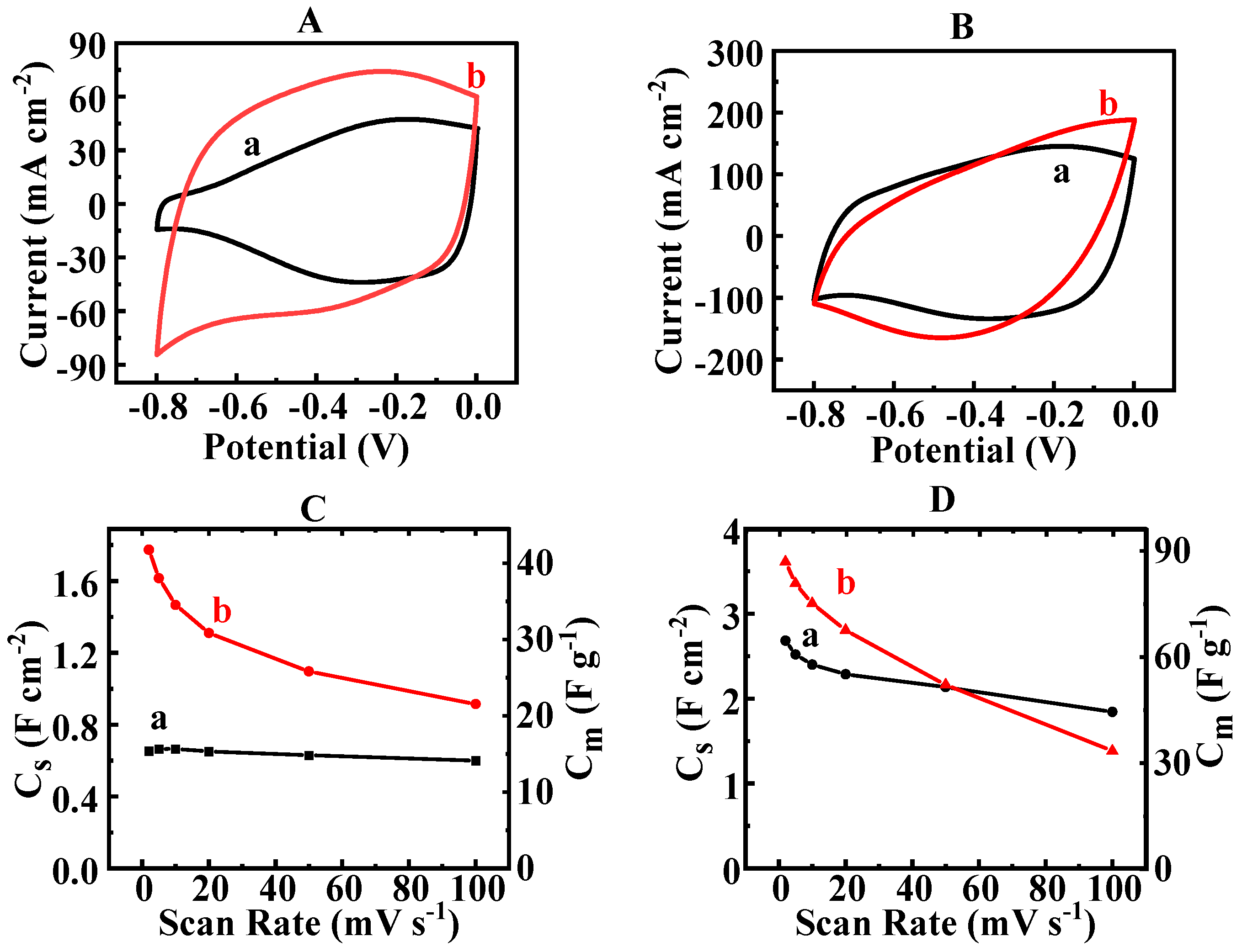
The results obtained for the ARSFO and HEBMSFO provided a platform for the development of composites containing SFO and PPy. Figure 4A shows the CV results for composite 1 prepared using the ARSFO and HEBMSFO. Composite 1 prepared using the ARSFO showed an enhanced current at potentials above −0.5 V (Figure 4A (a)). This can be attributed to the capacitive contribution of PPy. It should be noted that the ARSFO showed a decrease in current with an increasing potential above -0.5 V (Figure 3A (a)). HEBM resulted in an enhanced contribution of the SFO, and the CV results for composite 1, prepared using HEBMSFO, exhibited an improved shape, which approached the desired ideal rectangular shape in CV for pseudocapacitive materials (Figure 4A (b)). The composite 2 electrode showed a similar shape in the CV and an enhanced current (Figure 4B (a)). The improved shape in the CV indicated synergy between the contributions of SFO and PPy in different parts of the CV window. The CV results for composite 3 deviated from a rectangular shape (Figure 4B (b)). Composite 4, with a greater PPy content, showed similar CV results (Figure S3). Analysis of the capacitances of composite 1, prepared using the ARSFO and HEBMSFO, supplied further evidence of the beneficial impact of HEBM, which resulted in higher capacitances at varying scan rates (Figure 4C and Figure S4). The capacitance of composite 1 prepared using HEBMSFO was 1.77 F cm−2 at 2 mV s−1. Composites 2 and 3 displayed capacitances of 2.68 and 3.61 F cm−2, respectively, at 2 mV s−1. However, composite 2 displayed improved capacitance retention and a higher capacitance at increased scan rates (Figure 4D). Composite 4, with a greater PPy content, did not exhibit a significant improvement in capacitance relative to composite 3 (Figures S3 and S5).
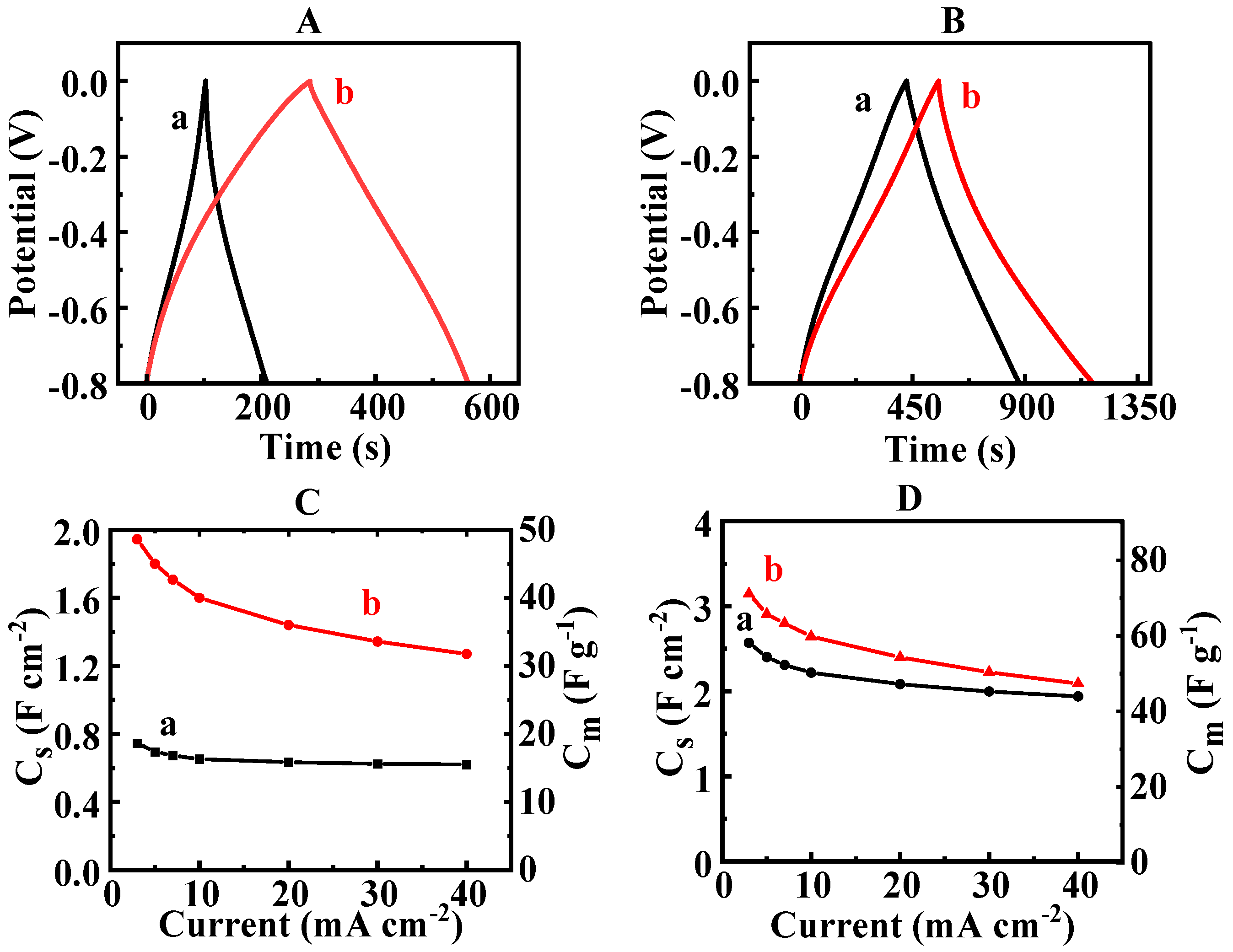
Figure 5 and Figure S3 show the CP data for composites 1–4. The CP data showed significantly longer charge–discharge time for composite 1 prepared using HEBMSFO compared to that prepared using the ARSFO at a current density of 3 mA cm−2 and at higher current densities in the range of 3–40 mA cm−2. The longer charge–discharge time indicated higher capacitance. Composite 3 showed a slightly longer charge–discharge time compared to composite 2 at a current density of 3 mA cm−2. However, the difference decreased with an increasing current density. The capacitances obtained from the CP data were 0.75 and 1.94 F cm−2 at 3 mA cm−2 and 0.62 and 1.27 F cm−2 at 40 mA cm−2 for the composite 1 electrodes prepared using the ARSFO and HEBMSFO, respectively. Composites 2 and 3 prepared using HEBMSFO showed capacitances of 2.57 and 3.14 F cm−2 at 3 mA cm−2 and 1.94 and 2.09 F cm−2 at 40 mA cm−2, respectively. Composite 4, with a greater PPy content, did not display a significant increase in capacitance compared to Composite 3.
The impedance spectroscopy data are summarized in Figure 6 and Figure S3E. The application of HEBM led to reduced resistance R = Z’ of the SFO and composite electrodes. The analysis of the data for the electrodes prepared using the ARSFO and HEBMSFO showed the beneficial effect of GD, which also resulted in lower resistances. Investigation of the composite electrodes showed that adding the conductive PPy polymer led to significantly lower resistances.
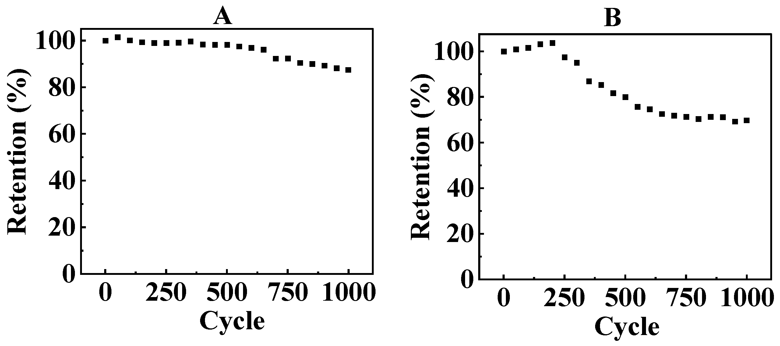
The testing results revealed the good capacitive properties of composite 2, which exhibited increased capacitance relative to composite 1 and an improved shape in CV and better capacitance retention and higher capacitance at high scan rates compared to composites 3 and 4. Moreover, composite 2 showed better cycling stability compared to composite 3. Figure 7 shows the cycling behavior of composites 2 and 3. The capacitance retention of composite 2 was 89.5% after 1000 cycles, whereas the capacitance retention of composite 3 was only 69.8% for the same number of cycles. Therefore, composite 2 was selected for further investigation of its magnetic properties and the fabrication of a supercapacitor device.
In addition to high capacitance, composite 2 showed magnetic properties. Figure 8 shows the magnetic measurement results. The ARSFO exhibited typical magnetic hysteresis curves, with a spontaneous magnetization of about 50 emu g−1.
HEBM resulted in a reduction in spontaneous magnetization and the coercive field. The spontaneous magnetization of SFO after HEBM was about 27 emu g−1. A reduction in spontaneous magnetization and the coercive field of magnetic materials with a reduction in particle size was reported in literature [40,41,42,43]. It was linked to different factors, such as the formation of a magnetically “dead” region on the particle surface with a partially disordered crystalline structure, a decrease in blocking temperature and a transition to a superparamagnetic state. Composite 2 showed a typical ferrimagnetic hysteresis loop with a spontaneous magnetization of approximately 12 emu g−1. Therefore, composite 2 combined high electrochemical capacitance with ferrimagnetic properties.
Composite 2 was utilized for the construction of an anode for an asymmetric electrochemical capacitor device. MnO2 was selected for the fabrication of the cathode. It is known that MnO2 exhibits high capacitance in the positive potential range in a Na2SO4 electrolyte [44,45,46]. Thus, MnO2 is an important component of the cathodes for the construction of asymmetric electrochemical capacitor devices [47,48,49]. The active material mass loading of each electrode was 40 mg cm−2. The CV results for the device did not display redox peaks in the voltage range of 1.5 V (Figure 9A). At low scan rates, the CV results displayed a nearly ideal rectangular shape. The CP measurements showed nearly triangular dependencies (Figure 9B). The devices showed capacitances of 1.52 F cm−2 at a scan rate of 2 mV s−1 and at a current density of 3 mA cm−2 (Figure 9C,D). The electrolyte mass transfer limitations resulted in a reduction in the capacitance with a reduced charge–discharge time. The total device’s impedance (Figure 9E) included the contributions of the cathode, the anode and the electrolyte in the separator membrane. The capacitance of the device displayed an increase during the first 700 cycles. This capacitance increase has been observed in other asymmetric devices containing MnO2 cathodes and attributed to partial oxidation of the non-stoichiometric MnO2 phase [50]. It is because of this that using the precipitation method [28] for the fabrication of MnO2 powders for cathodes resulted in the fabrication of a birnessite phase [51,52] containing not only Mn4+ but also Mn3+ ions. The asymmetric devices obtained were used to power a light-emitting diode (LED) display (Figure S6).
The results of this investigation showed the beneficial effect of a conceptually new approach based on the use of GD as a surfactant–charge transfer mediator and HEBM for the fabrication of SFO electrodes with enhanced capacitance. This finding opens up an avenue for the fabrication of other MOPC electrodes and devices with enhanced capacitance. Another important finding was the synergy of the contribution of the SFO and PPy, which facilitated the fabrication of advanced electrodes and devices with a high capacitance, an enlarged voltage window in an aqueous sodium sulfate electrolyte and low resistance.

4. Conclusions

The application of HEBM and GD allowed for the construction of SFO electrodes with a large areal capacitance of 1.29 F cm−2, on par with the capacitances of advanced MOPC materials. In contrast to previous investigations, good capacitive behavior was achieved in a negative potential range. The ability to achieve high capacitance in a Na2SO4 electrolyte offers environmental benefits and presents a path for the fabrication of novel asymmetric electrochemical capacitors. The use of HEBM and GD allowed for enhanced electrochemical performance of the SFO material at a practical active mass loading of 40 mg cm−2. HEBM resulted in a significant reduction in particle size, which enabled increased access of the electrolyte to the active surface area of the SFO particles. GD acted as a co-surfactant and charge transfer mediator which facilitated charge storage reactions. The charging mechanism of SFO was proposed, which was based on Fe3+/Fe2+ reduction reactions in the negative potential range. HEBM of the SFO enabled the construction of SFO-PPy electrodes with an improved capacitance. Composites 1–4 showed enhanced capacitive properties and reduced impedance because of the synergistic contributions of the SFO and PPy. The best capacitive performance was achieved using composite 2. The magnetic measurements showed a reduction in magnetization with a decreasing particle size of SFO. Composite 2 combined advanced capacitive properties and relatively high magnetization, which established it as a promising MOPC material. An asymmetric supercapacitor device with a composite 2 anode and a MnO2 cathode showed a high capacitance of 1.52 F cm−2 in a voltage window of 1.5 V.

Supplementary Materials

The following supporting information can be downloaded at https://www.mdpi.com/article/10.3390/jcs8090351/s1. Figure S1: Capacitances of ARSFO and HEBMSFO; Figure S2: Structure, adsorption mechanism and redox reaction of CD; Figure S3: Capacitive properties of composite 4; Figure S4: Influence of HEBM on capacitive properties of composite 1; Figure S5: Capacitive properties of SFO-PPy composites; Figure S6: LED display powered by asymmetric capacitors.

Author Contributions

Conceptualization, M.M. and I.Z.; methodology, M.M.; software, M.M.; validation, M.M. and I.Z.; formal analysis, M.M.; investigation, M.M.; resources, I.Z.; data curation, M.M.; writing—original draft preparation, M.M. and I.Z.; writing—review and editing, M.M. and I.Z.; supervision, I.Z.; project administration, I.Z.; funding acquisition, I.Z. All authors have read and agreed to the published version of the manuscript.

Funding

This research was funded by the Natural Sciences and Engineering Research Council of Canada, grant number RGPIN-2018-04014, and the CRC program.

Data Availability Statement

The data contained within the article are available.

Acknowledgments

The electron microscopy investigations were performed at the Canadian Centre for Electron Microscopy.

Conflicts of Interest

The authors declare no conflicts of interest.

References

  1. Srinivasan, G. Magnetoelectric composites. Annu. Rev. Mater. Res. 2010, 40, 153–178. [Google Scholar] [CrossRef]
  2. Eerenstein, W.; Mathur, N.; Scott, J.F. Multiferroic and magnetoelectric materials. Nature 2006, 442, 759–765. [Google Scholar] [CrossRef] [PubMed]
  3. Nan, C.-W.; Bichurin, M.; Dong, S.; Viehland, D.; Srinivasan, G. Multiferroic magnetoelectric composites: Historical perspective, status, and future directions. J. Appl. Phys. 2008, 103, 031101. [Google Scholar] [CrossRef]
  4. Venevtsev, Y.N.; Gagulin, V.V.; Zhitomirsky, I.D. Material science aspects of seignette-magnetism problem. Ferroelectrics 1987, 73, 221–248. [Google Scholar] [CrossRef]
  5. Schmid, H. Multi-ferroic magnetoelectrics. Ferroelectrics 1994, 162, 317–338. [Google Scholar] [CrossRef]
  6. Fang, C.; Kools, F.; Metselaar, R.; De Groot, R. Magnetic and electronic properties of strontium hexaferrite SrFe12O19 from first-principles calculations. J. Phys. Condens. Matter 2003, 15, 6229. [Google Scholar] [CrossRef]
  7. Kostishyn, V.; Panina, L.; Timofeev, A.; Kozhitov, L.; Kovalev, A.; Zyuzin, A. Dual ferroic properties of hexagonal ferrite ceramics BaFe12O19 and SrFe12O19. J. Magn. Magn. Mater. 2016, 400, 327–332. [Google Scholar] [CrossRef]
  8. Lee, J.; Cho, S.Y.; Kim, I.; Rouleau, C.M.; Kang, K.; Ryu, S.; Heo, Y.; Keum, J.K.; Pajerowski, D.M.; Kim, Y. Multiferroism in strained strontium hexaferrite epitaxial thin films. Phys. Rev. Mater. 2024, 8, 024401. [Google Scholar] [CrossRef]
  9. Tan, G.; Chen, X. Synthesis, structures, and multiferroic properties of strontium hexaferrite ceramics. J. Electron. Mater. 2013, 42, 906–911. [Google Scholar] [CrossRef]
  10. Santos-López, F.; Díaz-Castañón, S. Magnetic Properties and Electric Hysteresis in SrFe12O19 Hexaferrites at Low Sintered Temperatures. J. Supercond. Nov. Magn. 2024, 37, 881–888. [Google Scholar] [CrossRef]
  11. Tan, G.; Huang, Y.; Sheng, H. Magnetoelectric response in multiferroic SrFe12O19 ceramics. PLoS ONE 2016, 11, e0167084. [Google Scholar] [CrossRef] [PubMed]
  12. Kostishyn, V.; Panina, L.; Kozhitov, L.; Timofeev, A.; Kovalev, A. Synthesis and multiferroic properties of M-type SrFe12O19 hexaferrite ceramics. J. Alloys Compd. 2015, 645, 297–300. [Google Scholar] [CrossRef]
  13. Qiang, G.; Jin, Y.; Lu, X.; Cui, X.; Deng, D.; Kang, B.; Yang, W.; Cao, S.; Zhang, J. Temperature effect on the magnetic property and ferroelectricity in hexaferrite SrFe12O19. Appl. Phys. A 2016, 122, 681. [Google Scholar] [CrossRef]
  14. Katlakunta, S.; Raju, P.; Meena, S.S.; Srinath, S.; Sandhya, R.; Kuruva, P.; Murthy, S.R. Multiferroic properties of microwave sintered BaTiO3–SrFe12O19 composites. Phys. B Condens. Matter 2014, 448, 323–326. [Google Scholar] [CrossRef]
  15. Stingaciu, M.; Reuvekamp, P.; Tai, C.-W.; Kremer, R.; Johnsson, M. The magnetodielectric effect in BaTiO3–SrFe12O19 nanocomposites. J. Mater. Chem. C 2014, 2, 325–330. [Google Scholar] [CrossRef]
  16. Singh, A.; Suri, S.; Kumar, P.; Kaur, B.; Thakur, A.K.; Singh, V. Effect of temperature and frequency on electrical properties of composite multiferroic of lead titanate and strontium hexaferrite (PbTiO3–SrFe12O19). J. Alloys Compd. 2018, 764, 599–615. [Google Scholar] [CrossRef]
  17. Martínez-Pérez, J.; Bolarín-Miró, A.; Pedro-García, F.; Cortés-Escobedo, C.; Barba-Pingarrón, A.; Sánchez-De Jesús, F. Magnetic and dielectric characterization of xBiFeO3:(1−x)SrFe12O19 multiferroic composites. J. Alloys Compd. 2019, 808, 151700. [Google Scholar] [CrossRef]
  18. Das, A.; Chatterjee, S.; Bandyopadhyay, S.; Das, D. Enhanced magnetoelectric properties of BiFeO3 on formation of BiFeO3/SrFe12O19 nanocomposites. J. Appl. Phys. 2016, 119, 234102. [Google Scholar] [CrossRef]
  19. Yao, X.; Zhou, J.-P.; Zhang, X.-L.; Lei, R.-Y. Investigation on the electrical and magnetic properties of PVDF/SrFe12O19 composite membranes. J. Magn. Magn. Mater. 2023, 572, 170601. [Google Scholar] [CrossRef]
  20. Prathipkumar, S.; Hemalatha, J. Magnetoelectric behavior and magnetic field-tuned energy storage capacity of SrFe12O19 nanofiber reinforced P (VDF-HFP) composite films. J. Magn. Magn. Mater. 2022, 555, 169378. [Google Scholar] [CrossRef]
  21. Sikkema, R.; Zhitomirsky, I. Magnetic supercapacitors: Charge storage mechanisms, magnetocapacitance, and magnetoelectric phenomena. Appl. Phys. Rev. 2023, 10, 021307. [Google Scholar] [CrossRef]
  22. Elanthamilan, E.; Wang, S.-F. Surfactant assisted synthesis of strontium hexaferrite microspheres for the fabrication of high-performance asymmetric supercapacitors. New J. Chem. 2023, 47, 9174–9185. [Google Scholar] [CrossRef]
  23. Rezaie, E.; Rezanezhad, A.; Ghadimi, L.S.; Hajalilou, A.; Arsalani, N. Effect of calcination on structural and supercapacitance properties of hydrothermally synthesized plate-like SrFe12O19 hexaferrite nanoparticles. Ceram. Int. 2018, 44, 20285–20290. [Google Scholar] [CrossRef]
  24. Fu, M.; Chen, W.; Zhu, X.; Yang, B.; Liu, Q. Crab shell derived multi-hierarchical carbon materials as a typical recycling of waste for high performance supercapacitors. Carbon 2019, 141, 748–757. [Google Scholar] [CrossRef]
  25. Snook, G.A.; Kao, P.; Best, A.S. Conducting-polymer-based supercapacitor devices and electrodes. J. Power Sources 2011, 196, 1–12. [Google Scholar] [CrossRef]
  26. Pana, O.; Soran, M.; Leostean, C.; Macavei, S.; Gautron, E.; Teodorescu, C.; Gheorghe, N.; Chauvet, O. Interface charge transfer in polypyrrole coated perovskite manganite magnetic nanoparticles. J. Appl. Phys. 2012, 111, 044309. [Google Scholar] [CrossRef]
  27. Xu, J.; Wang, D.; Yuan, Y.; Wei, W.; Gu, S.; Liu, R.; Wang, X.; Liu, L.; Xu, W. Polypyrrole-coated cotton fabrics for flexible supercapacitor electrodes prepared using CuO nanoparticles as template. Cellulose 2015, 22, 1355–1363. [Google Scholar] [CrossRef]
  28. Wang, Y.; Liu, Y.; Zhitomirsky, I. Surface modification of MnO2 and carbon nanotubes using organic dyes for nanotechnology of electrochemical supercapacitors. J. Mater. Chem. A 2013, 1, 12519–12526. [Google Scholar] [CrossRef]
  29. Chen, R.; Yu, M.; Sahu, R.P.; Puri, I.K.; Zhitomirsky, I. The development of pseudocapacitor electrodes and devices with high active mass loading. Adv. Energy Mater. 2020, 10, 1903848. [Google Scholar] [CrossRef]
  30. Reddy, R.N.; Reddy, R.G. Sol–gel MnO2 as an electrode material for electrochemical capacitors. J. Power Sources 2003, 124, 330–337. [Google Scholar] [CrossRef]
  31. Jeong, Y.; Manthiram, A. Nanocrystalline manganese oxides for electrochemical capacitors with neutral electrolytes. J. Electrochem. Soc. 2002, 149, A1419. [Google Scholar] [CrossRef]
  32. Dong, W.; Sakamoto, J.S.; Dunn, B. Electrochemical properties of vanadium oxide aerogels. Sci. Technol. Adv. Mater. 2003, 4, 3–11. [Google Scholar] [CrossRef]
  33. Kim, E.; Liu, Y.; Shi, X.W.; Yang, X.; Bentley, W.E.; Payne, G.F. Biomimetic approach to confer redox activity to thin chitosan films. Adv. Funct. Mater. 2010, 20, 2683–2694. [Google Scholar] [CrossRef]
  34. Kim, E.; Liu, Y.; Bentley, W.E.; Payne, G.F. Redox capacitor to establish bio-device redox-connectivity. Adv. Funct. Mater. 2012, 22, 1409–1416. [Google Scholar] [CrossRef]
  35. Wang, G.-L.; Xu, J.-J.; Chen, H.-Y. Dopamine sensitized nanoporous TiO2 film on electrodes: Photoelectrochemical sensing of NADH under visible irradiation. Biosens. Bioelectron. 2009, 24, 2494–2498. [Google Scholar] [CrossRef]
  36. Radich, E.J.; Peeples, N.R.; Santra, P.K.; Kamat, P.V. Charge transfer mediation through CuxS. The hole story of CdSe in polysulfide. J. Phys. Chem. C 2014, 118, 16463–16471. [Google Scholar] [CrossRef]
  37. Tallman, D.; Vang, C.; Wallace, G.; Bierwagen, G. Direct electrodeposition of polypyrrole on aluminum and aluminum alloy by electron transfer mediation. J. Electrochem. Soc. 2002, 149, C173. [Google Scholar] [CrossRef]
  38. Ariyanayagamkumarappa, D.; Zhitomirsky, I. Electropolymerization of polypyrrole films on stainless steel substrates for electrodes of electrochemical supercapacitors. Synth. Met. 2012, 162, 868–872. [Google Scholar] [CrossRef]
  39. Seung-Hoon, S.; Young-Je, Y. Characteristics of mediated enzymatic nitrate reduction by gallocyanine-bound nanoporous electrode. J. Microbiol. Biotechnol. 2006, 16, 505–510. [Google Scholar]
  40. Berkowitz, A.; Schuele, W.; Flanders, P. Permanent magnets and fine particles. J. Appl. Phys 1968, 39, 1261. [Google Scholar] [CrossRef]
  41. Morales, M.; Andres-Verges, M.; Veintemillas-Verdaguer, S.; Montero, M.; Serna, C. Structural effects on the magnetic properties of γ-Fe2O3 nanoparticles. J. Magn. Magn. Mater. 1999, 203, 146–148. [Google Scholar] [CrossRef]
  42. Liu, S.; Zhou, J.; Zhang, L. Effects of crystalline phase and particle size on the properties of plate-like Fe2O3 nanoparticles during γ-to α-phase transformation. J. Phys. Chem. C 2011, 115, 3602–3611. [Google Scholar] [CrossRef]
  43. Jeong, J.R.; Lee, S.J.; Kim, J.D.; Shin, S.C. Magnetic properties of γ-Fe2O3 nanoparticles made by coprecipitation method. Phys. Status Solidi 2004, 241, 1593–1596. [Google Scholar] [CrossRef]
  44. Zhang, X.; Yu, P.; Zhang, H.; Zhang, D.; Sun, X.; Ma, Y. Rapid hydrothermal synthesis of hierarchical nanostructures assembled from ultrathin birnessite-type MnO2 nanosheets for supercapacitor applications. Electrochim. Acta 2013, 89, 523–529. [Google Scholar] [CrossRef]
  45. Jayachandran, M.; Rose, A.; Maiyalagan, T.; Poongodi, N.; Vijayakumar, T. Effect of various aqueous electrolytes on the electrochemical performance of α-MnO2 nanorods as electrode materials for supercapacitor application. Electrochim. Acta 2021, 366, 137412. [Google Scholar] [CrossRef]
  46. Srither, S.; Karthik, A.; Arunmetha, S.; Murugesan, D.; Rajendran, V. Electrochemical supercapacitor studies of porous MnO2 nanoparticles in neutral electrolytes. Mater. Chem. Phys. 2016, 183, 375–382. [Google Scholar] [CrossRef]
  47. Cao, J.; Wang, Y.; Zhou, Y.; Ouyang, J.-H.; Jia, D.; Guo, L. High voltage asymmetric supercapacitor based on MnO2 and graphene electrodes. J. Electroanal. Chem. 2013, 689, 201–206. [Google Scholar] [CrossRef]
  48. Ou, T.-M.; Hsu, C.-T.; Hu, C.-C. Synthesis and characterization of sodium-doped MnO2 for the aqueous asymmetric supercapacitor application. J. Electrochem. Soc. 2015, 162, A5124. [Google Scholar] [CrossRef]
  49. Zhang, G.; Ren, L.; Hu, D.; Gu, H.; Zhang, S. Sulfuric acid etching for fabrication of porous MnO2 for high-performance supercapacitor. J. Colloid Interface Sci. 2018, 518, 84–91. [Google Scholar] [CrossRef]
  50. Demarconnay, L.; Raymundo-Piñero, E.; Béguin, F. Adjustment of electrodes potential window in an asymmetric carbon/MnO2 supercapacitor. J. Power Sources 2011, 196, 580–586. [Google Scholar] [CrossRef]
  51. Athouël, L.; Moser, F.; Dugas, R.; Crosnier, O.; Bélanger, D.; Brousse, T. Variation of the MnO2 Birnessite Structure upon Charge/Discharge in an Electrochemical Supercapacitor Electrode in Aqueous Na2SO4 Electrolyte. J. Phys. Chem. C 2008, 112, 7270–7277. [Google Scholar] [CrossRef]
  52. Ming, B.; Li, J.; Kang, F.; Pang, G.; Zhang, Y.; Chen, L.; Xu, J.; Wang, X. Microwave–hydrothermal synthesis of birnessite-type MnO2 nanospheres as supercapacitor electrode materials. J. Power Sources 2012, 198, 428–431. [Google Scholar] [CrossRef]
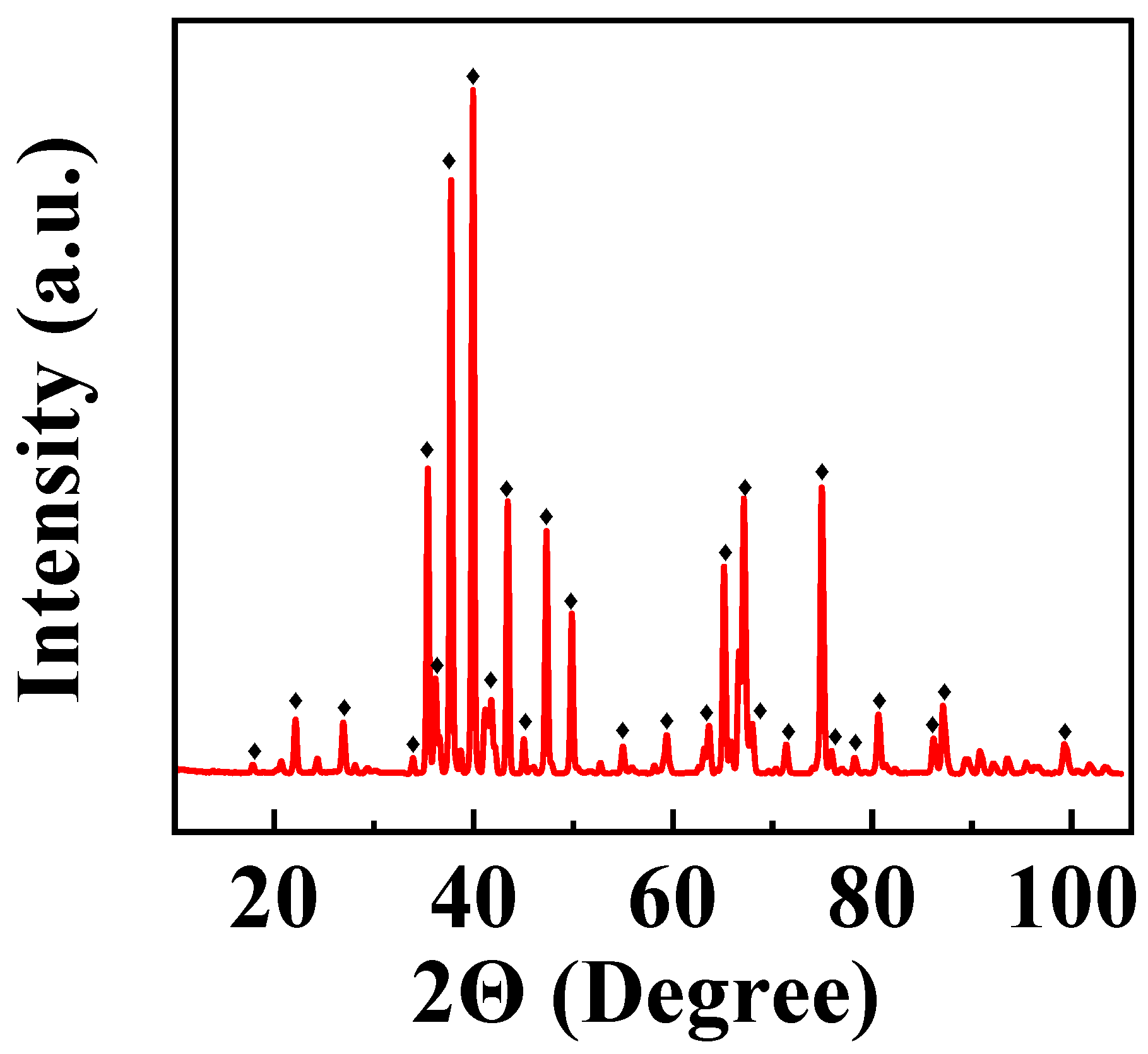
Figure 1. X-ray diffraction pattern of ARSFO. ♦—peaks corresponding to JCPDS file 04-016-5959.
Jcs 08 00351 g001
Figure 2. TEM images of (A) ARSFO and (B) HEBMSFO.
Jcs 08 00351 g002
Figure 3. (A,B) CV results at a scan rate of 50 mV s−1 for (A) ARSFO and (B) HEBMSFO, prepared (a) without GD and (b) using GD; (C,D) CP data at a current density of 5 mA cm−2 for (C) ARSFO and (D) HEBMSFO, prepared (a) without GD and (b) using GD; (E,F) capacitance derived from (E) CV data at different scan rates and (F) CP data at different current densities for (a,b) ARSFO and (c,d) HEBMSFO, for electrodes prepared (a,c) without GD and (b,d) with GD.
Jcs 08 00351 g003
Figure 4. (A,B) CVs at a scan rate of 50 mV s−1 for (A) composite 1, prepared using (a) ARSFO and (b) HEBMSFO, and (B) (a) composite 2 and (b) composite 3, prepared using HEBMSFO; (C,D) capacitances at different scan rates for (C) composite 1, prepared using (a) ARSFO and (b) HEBMSFO, and (D) (a) composite 2 and (b) composite 3, prepared using HEBM SFO.
Jcs 08 00351 g004
Figure 5. (A,B) CP data at a current density of 5 mA cm−1 for (A) composite 1, prepared using (a) ARSFO and (b) HEBMSFO, and (B) (a) composite 2 and (b) composite 3, prepared using HEBMSFO; (C,D) capacitances at different current densities for (C) composite 1, prepared using (a) ARSFO and (b) HEBMSFO, and (D) (a) composite 2 and (b) composite 3, prepared using HEBMSFO.
Jcs 08 00351 g005
Figure 6. EIS data for (A) ARSFO prepared (a) without GD and (b) with GD; (B) HEBMSFO prepared (a) without GD and (b) with GD; (C) composite 1 prepared using (a) ARSFO and (b) HEBMSFO; (D) (a) composite 2 and (b) composite 3.
Jcs 08 00351 g006
Figure 7. Cyclic behavior of (A) composite 2 and (B) composite 3.
Jcs 08 00351 g007
Figure 8. Magnetization versus magnetic field for (A) ARSFO, (B) HEBMSFO and (C) composite 2.
Jcs 08 00351 g008
Figure 9. (A) CV results at different scan rates, (B) CP data at different current densities, (C) capacitance calculated from CV data versus scan rate, (D) capacitance calculated from CP data versus current density, (E) Nyquist plot of EIS data, (F) cyclic stability for a device containing a composite 2 anode and a MnO2 cathode.
Jcs 08 00351 g009
Disclaimer/Publisher’s Note: The statements, opinions and data contained in all publications are solely those of the individual author(s) and contributor(s) and not of MDPI and/or the editor(s). MDPI and/or the editor(s) disclaim responsibility for any injury to people or property resulting from any ideas, methods, instructions or products referred to in the content.