Article

Enhancing Polylactic Acid/Carbon Fiber-Reinforced Biomedical Composites (PLA/CFRCs) with Multi-Walled Carbon Nanotube (MWCNT) Fillers: A Comparative Study on Reinforcing Techniques

by
Juan Antonio Paz-González
1,
Yadira Gochi-Ponce
2,*,
Carlos Velasco-Santos
3,
Enrique Alcudia-Zacarias
4,
Arturo Zizumbo-López
2,
Balter Trujillo-Navarrete
2,
Oscar Adrián Morales-Contreras
1 and
Luis Jesús Villarreal-Gómez
1,*
1
Facultad de Ciencias de la Ingeniería y Tecnología, Universidad Autónoma de Baja California, Blvd Universitario 1000, Unidad Valle de Las Palmas, Tijuana 22260, Baja California, Mexico
2
Tecnológico Nacional de México, Instituto Tecnológico de Tijuana, Campus Tijuana, Blvd. Alberto Limón Padilla S/N, Mesa de Otay, Tijuana 22500, Baja California, Mexico
3
Tecnológico Nacional de México, Instituto Tecnológico de Querétaro, Campus Querétaro, División de Estudios de Posgrado e Investigación, Santiago Zacatlán s/n Colonia Jardines de Santiago, Querétaro 76148, Querétaro, Mexico
4
Tecnológico Nacional de México/Centro Nacional de Investigación y Desarrollo Tecnológico—CENIDET, Interior Internado Palmira S/N, Colonia Palmira, Cuernavaca 62490, Morelos, Mexico
*
Authors to whom correspondence should be addressed.
J. Compos. Sci. 2025, 9(4), 167; https://doi.org/10.3390/jcs9040167
Submission received: 27 February 2025 / Revised: 24 March 2025 / Accepted: 25 March 2025 / Published: 29 March 2025

Abstract

:
The limited mechanical properties of composite materials, including stiffness, strength, and biocompatibility, restrict their effectiveness in biomedical applications. This research enhanced the mechanical properties and biocompatibility of polylactic acid and carbon fiber-reinforced composites (PLA/CFRCs) by incorporating multi-walled carbon nanotube (MWCNT) fillers. The methodology involved synthesizing MWCNTs and integrating them into PLA/CFRC laminates using fusion-blending, dispersion, and interlaminar spray-coating. Raman spectroscopy confirmed the presence of MWCNTs, with characteristic D and G band peaks and an ID/IG of 1.44 ± 0.089. SEM revealed MWCNTs in the PLA/CFRC matrix and allowed size determination, with an outer diameter range of 125–150 nm and a length of 14,407 ± 2869 nm. FTIR identified interactions between the matrix and the MWCNTs, evidenced by band shifts. TGA/DSC analysis showed thermal stability above 338 °C for all composites. The tensile tests revealed that all composites had values greater than 19 GPa for the elastic modulus and 232 MPa for the ultimate strength. Cytotoxicity assays confirmed biocompatibility, and all samples maintained a cell growth rate greater than 80%. This study highlighted the potential of nanotechnology to optimize the mechanical behavior of polymer-based composites, expanding their applicability in biomedical fields.

1. Introduction

The application of 3D-printed composite materials in medical applications is limited by non-optimal mechanical properties, including stiffness, strength, and biocompatibility, which are essential for the performance and longevity of medical implants. Current manufacturing techniques, including manual methods and 3D printing with polymers, are often combined with multiscale composite materials to tailor mechanical properties for specific applications [1,2,3,4,5]. Advanced materials manufactured using reinforcing fibers (carbon, glass, aramid) combined with nanometric filler materials (graphene, carbon nanotubes, metal nanoparticles) are called multiscale composites. These materials have been developed to improve their mechanical performance, allowing the customization of their properties through the selection and optimization of both the fibers and nanomaterials used as reinforcements and fillers [6]. These methods involve the incorporation of carbon nanostructures such as multi-walled carbon nanotubes (MWCNTs) and single-walled carbon nanotubes (SWCNTs) into polymeric matrices, which have shown improvements in elastic modulus, ultimate strength, hardness, toughness, and biocompatibility [7,8,9,10,11,12,13].
Despite these advances, significant challenges remain in optimizing the synthesis parameters for consistent MWCNT growth, achieving uniform dispersion in the polymer matrix, and ensuring strong adhesion between the matrix and nanostructures. Moreover, scaling up these methods for practical use poses further difficulties, and the mechanical improvements achieved can vary widely depending on different CNT concentrations and synthesis techniques. Methods such as electric arc evaporation, laser ablation, chemical vapor deposition, electrolysis, hydro-thermal methods, ball milling, and pyrolytic nebulization have been explored for CNT synthesis [14,15,16,17,18]. Among these, pyrolytic nebulization is widely used due to its scalability and low cost. However, it is highly dependent on parameters such as heating time, catalysis type, and experimental conditions, making consistent MWCNT growth challenging [16,19,20].
Studies have demonstrated that incorporating carbon nanostructures as reinforcements in polymeric materials can significantly modify their thermal, mechanical, and biocompatibility parameters, with reinforcements ranging from 0.1% to 20% by weight [8,9,12,21,22,23,24,25,26]. Techniques such as melt mixing, dissolution, polymerization, extrusion, dispersion, and spraying have been used to incorporate nanostructures into polymers [7,8,9,10,11,12]. For instance, interlaminar spray-coating of MWCNT nanofillers on pre-impregnated carbon fabrics demonstrated that greater energy was needed for crack propagation, indicating improved interlaminar fracture resistance [12]. Similarly, ultrasonic wave dispersion improved the tensile strength and toughness of epoxy resins mixed with carbon nanotubes [27].
Although numerous nanotube-reinforced materials already exist, research has shown that small quantities can achieve significant changes in mechanical, thermal, and biocompatibility properties [18,28]. In addition, studies have demonstrated their influence both at the interface of laminates and when incorporated independently into thermosetting and thermoplastic polymers to evaluate their operation and performance. On the other hand, materials have been developed that combine manufacturing techniques aimed at achieving particular characteristics of the materials. For example, structural composite materials for hip prostheses have been developed, combining printing polymers of polylactic acid (PLA) and carbon fabric-reinforced composite materials (CFRCs), with characteristics similar to bone [29]. Our motivation for studying the effect of nanotubes arises from interest in exploring various incorporation techniques, which influence the interaction of nanotubes with different interfaces within the structural composite, and ultimately assessing their mechanical and biocompatibility behavior.
The proposed technology addresses these limitations by synthesizing multi-walled carbon nanotubes (MWCNTs) via spray-pyrolysis and incorporating them into PLA/CFRCs. This approach involves the integration of MWCNTs via interlaminar spray-coating, fusion-blending, and dispersion in epoxy resin. These techniques provide more uniform dispersion, better adhesion, and enhanced mechanical properties. Consequently, our technology has the potential to significantly improve the performance of polymer composites, making them more suitable for demanding applications such as medical implants.

2. Materials and Methods

2.1. Materials

PLA (Shenzhen Esun Industrial, Shenzhen, China) filament was used to make 3D-printed parts. Carbon fiber 2/2 twill weave (Torayca 3k, Lacq, France) served as the reinforcement, and epoxy resin (PRO-SET LAM-125, LAM-229, Bay City, MI, USA) formed the PLA/CFRC composite structure matrix. For the synthesis of MWCNT, Toluene (C7H8) and Ferrocene (C10H10Fe) of the Sigma-Aldrich brand were employed. Table 1 shows the properties of the materials according to the technical data sheet.

2.2. Synthesis of MWCNTs and Manufacturing of Composite Materials with MWCNT Fillers

2.2.1. Synthesis of Nanotubes by the Spray-Pyrolysis Method

The synthesis of carbon nanotubes was carried out using the spray-pyrolysis technique [16,19,20]. Toluene and Ferrocene were employed as precursors for forming the nanotubes, and the resulting solution underwent sonication to facilitate the mixing process. Subsequently, the solution entered a peristaltic pump (Spetec GmbH, model PERIMAX 12, Erding, Bavaria, Germany) with a flow rate of 10 mL/h that dosed the nebulizer (Agilent Technologies, model U-series, Santa Clara, CA, USA) to pulverize the mixture. Argon gas was injected to the system to transport the solution through the quartz tube in a horizontal furnace (ThermoFisher Lindberg BlueM, Thermo Fisher Scientific, Waltham, MA, USA) that was at a controlled temperature above 850 °C, as shown in Figure 1.
The synthesis of the MWCNT lasted for 30 min, using 6 mL of Toluene and 111.8 mg of Ferrocene with a concentration of 0.1 M for each process performed. Once the reaction in the oven was completed, the quartz tube containing the product was allowed to cool to room temperature. It was then removed, and MWCNTs were extracted by scraping the walls with an aluminum rod, thus separating the nanomaterials from the container.

2.2.2. Manufacturing of 3D-Printed Plates with PLA

The PLA plates were manufactured using the fused deposition method [29,30] in a 3D printer (Ender-3 3D Printer Basic Combo, Shenzhen, China), with dimensions of 150 × 150 × 1 mm, with six layers. The thickness of the first and last layer was 0.2 mm, while the four internal layers had a thickness of 0.15 mm, oriented to [(±45)]3, and a printing speed of 75 mm/s at 80% of the filling density, with a total of twelve printed plates.

2.2.3. Composite of PLA/CFRC

The first composite, PLA/CFRC, was fabricated by impregnating the mold with epoxy resin in the initial layer. Then, a PLA plate was placed, followed by four layers of 2/2 carbon fiber twill-type fabric with [(0/90)]4 orientation, impregnated with epoxy resin. The procedure was repeated until obtaining the configuration of PLA/CFRC/PLA/CFRC/PLA, with dimensions of 150 × 150 mm and a thickness of 5 mm.

2.2.4. Fusion-Blended Composite of PLA and MWCNT (PLA-MWCNT/CFRC)

The PLA-MWCNT reinforcement was prepared using the direct melting method [11]. The MWCNTs, with 0.1 wt% PLA, were manually mixed in a bag and then fed into the extruder hopper to produce the PLA-MWCNT filament. The mixing was carried out in a single-screw extruder (FILABOT), with a temperature of 180 °C. Later, it passed through a cooling bed with fans. Afterward, the PLA-MWCNT samples were processed using the fused deposition process, following the parameters established for the manufacturing of 3D-printed parts. Finally, the plates of PLA-MWCNT and carbon fiber twill-type fabric were impregnated with epoxy resin (PLA-MWCNT/CFRC), as illustrated in Figure 2. The stacking sequence was repeated until it became similar to the corresponding PLA/CFRC.

2.2.5. Composite with Ultrasonic Dispersion of Carbon Nanotubes in Epoxy Resin (PLA/CFRC-MWCNT)

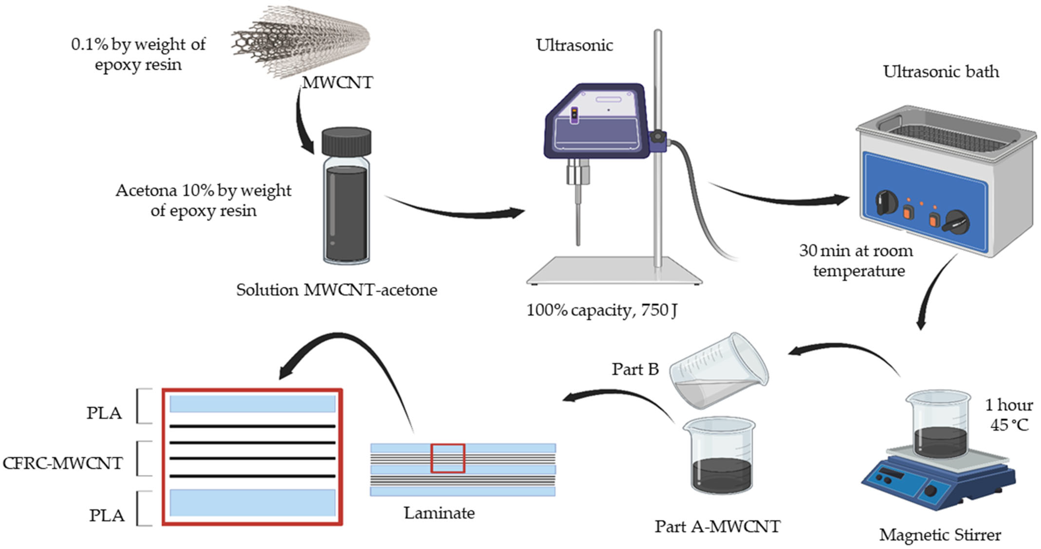
The epoxy composite reinforced with nanostructures (PLA/CFRC-MWCNT) was produced by dispersing MWCNTs in epoxy resin using ultrasonic waves [27,31]. The MWCNTs, with 0.1 wt% resins, were dispersed in acetone (10 wt% resin). An ultrasonic probe was used to break up clumps in the solution at 100% capacity, applying 750 J. Afterwards, it became dispersed for 30 min in an ultrasonic bath. Thereafter, it was added to the epoxy resin (Part A) and mixed through magnetic stirring for 1 h at 45 °C. Afterward, the mixture was combined with the hardener (Part B) in proportions of 3:1, respectively, through manual stirring with the help of a glass rod for 60 s. Consecutively, composite impregnation was performed through the manual method, as seen in Figure 3.

2.2.6. Composite with Interlaminar Spray-Coating (PLA/MWCNT/CFRC)

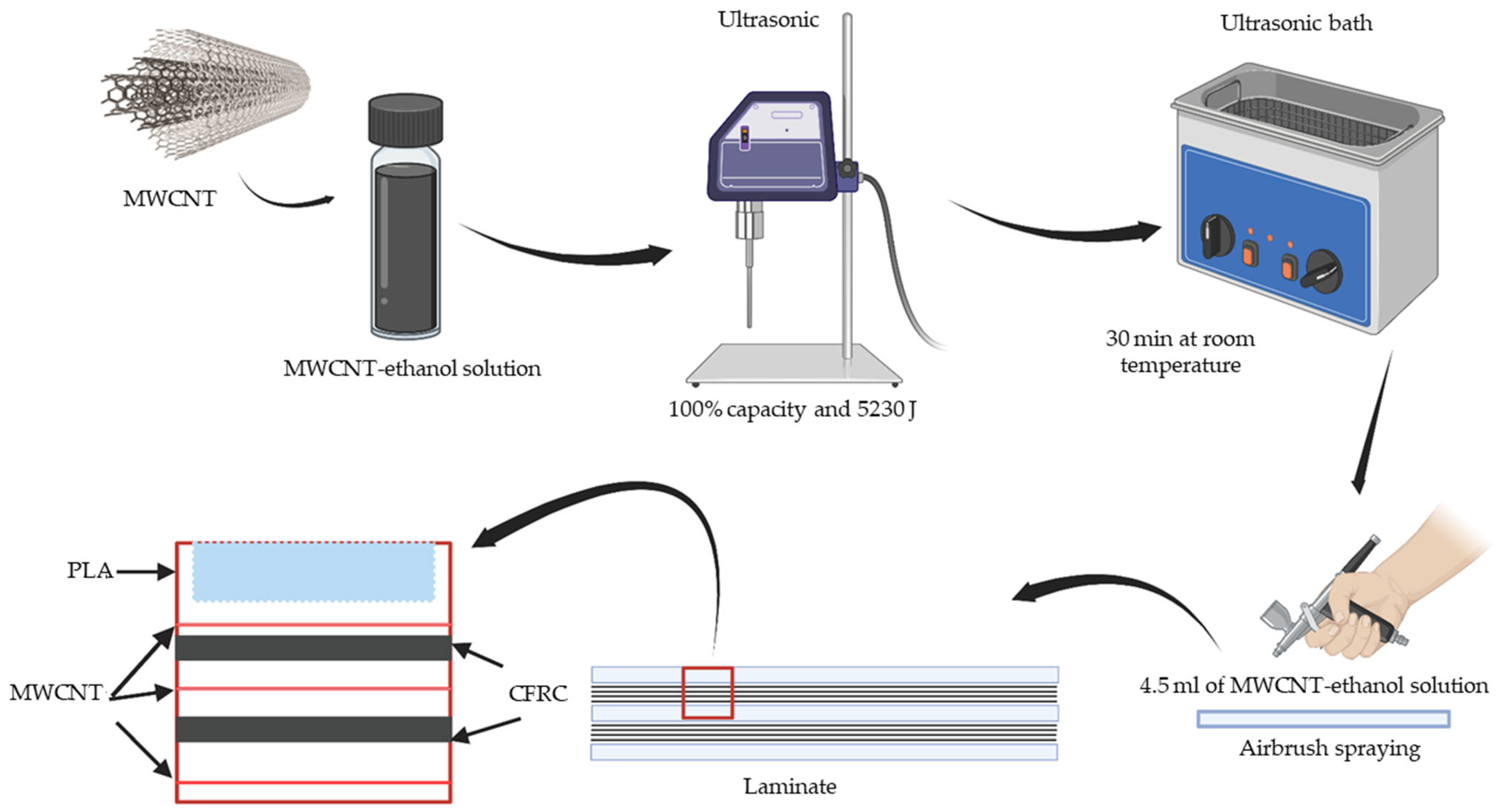
To fabricate the composite (PLA/MWCNT/CFRC), the spray-coating method [32,33] was applied according to the scheme presented in Figure 4. An amount of 64 mg of MWCNT was weighted and dispersed in 45 mL of ethanol using an ultrasonic probe at 100% capacity and 5230 J energy to break up the agglomerations. Subsequently, it underwent an ultrasonic bath for 30 min. Then, the MWCNT–ethanol solution was separated into 4.5 mL portions. Each portion was added into the airbrush tank (Truper® AERO-35, Truper S.A. de C.V., Jilotepec, Estado de México, Mexico). Therefore, the first 3D-printed plate was positioned and impregnated with resin using the manual method. Then, the MWCNT–ethanol solution was sprayed onto the surface in a constant pattern to cover the entire surface, using the entire 4.5 mL solution. This process was repeated at each laminate interface, with 10 layers and 6.4 mg of MWCNT per interlayer. A summary of the methods used to manufacture the composite materials is presented in Table 2.

2.3. Characterization Techniques

2.3.1. Raman Spectroscopy

The Raman spectrometry analysis was conducted using a Thermo Scientific DXR Smart Raman spectrometer (Thermo Scientific, Waltham, MA, USA) with a 50 to 3300 Raman shift (cm−1) and the laser operating at 780 nm. These analyses were carried out to identify the crystalline structure of the MWCNTs synthesized. The sample, in powder form, was placed in a sample holder before the analysis. This technique involved illuminating the sample with a beam of light, which interacted with the sample molecules, causing a dispersion of light usually represented by wavelengths. This dispersion provided information about vibrational and rotational transitions, the mode of which was unique to each molecule.

2.3.2. Scanning Electron Microscopy (SEM)

The SEM analysis was performed using a Tescan® VEGA3 scanning electron microscope (Tescan, Brno, Czech Republic). SEM was used to observe the morphology of the synthesized MWCNTs. The preparation method consisted of making a solution of MWCNTs and ethanol. The solution was then sonicated for 30 min, and a drop of the solution was deposited onto the sample holder, which had been previously prepared with aluminum conductive tape. It was subjected to a heat source to evaporate the solvent. Finally, the samples were introduced into the microscope chamber to obtain images. It also allowed the observation of the morphology of the fractured surfaces of the specimens subjected to tension.

2.3.3. Fourier Transform Infrared Spectroscopy (FTIR)

FTIR analysis was performed using a Spectrum Two N FT-NIR spectrometer (PerknElmer, Madrid, Spain) and a zinc selenide (ZnSe) crystal. Spectra, collected in the range of 4000 to 450 cm−1, were recorded using four scans with a resolution of 4.0 cm−1. Measurements were performed directly on solid samples of PLA-MWCNT/CFRC, PLA/CFRC-MWCNT, PLA/MWCNT/CFRC, epoxy resin, PLA, and MWCNT powder.

2.3.4. Thermal Analysis (TGA/DSC)

For the thermogravimetric analysis (TGA), an SDT 2960 simultaneous DSC-TGA (TA Instruments, New Castle, DE, USA) was used. A total of 15–20 mg of samples (PLA-MWCNT/CFRC, PLA/CFRC-MWCNT, PLA/MWCNT/CFRC, PLA, epoxy resin, and MWCNT) was placed in an aluminum crucible and heated at a rate of 20 °C/min to 800 °C from an initial temperature of 25 °C under a nitrogen atmosphere. For the differential scanning calorimetry (DSC) analysis, a Q2000 DSC (TA Instruments, New Castle, DE, USA) was used. A total of 4.5 mg of the samples was placed in an airtight aluminum crucible. The temperature program consisted of two heating cycles, where the first heating ramp was used to erase the thermal history of the sample. The samples were heated at a rate of 10 °C/min, starting from an initial temperature of 25 °C and reaching a final temperature of 200 °C, under a nitrogen atmosphere. The second heating cycle was used for data acquisition.

2.3.5. Mechanical Characterization

The samples for the tensile test resulted from fabrication using a numerical control machine (made in the laboratory). A four-edged carbide cutter with a diameter of 6.35 mm was utilized. The PLA/CFRC, PLA-MWCNT/CFRC, PLA/CFRC-MWCNT, and PLA/MWCNT/CFRC specimens were machined until a bone-type specimen was obtained according to ASTM D638 [34], with five samples for each nanocomposite specimen. Subsequently, the tensile tests were performed on the SHIMADZU AG-X Plus universal testing machine (Shimadzu, Kyoto, Japan), equipped with a 100 kN load cell. The samples were clamped with two jaws, and the tension test was conducted at a transverse speed of 2 mm/min. An Epsilon 3542-050 M-050-ST extensometer (Epsilon Technology, Jackson, WY, USA) was used to measure the strain during the tensile tests. Subsequently, the tensile strength and elastic modulus were calculated.

2.3.6. Cytotoxicity Assays

Cell Culture

For the cell viability assay, primary human mononuclear cells (lymphocytes and monocytes) from peripheral blood were obtained using the Ficoll–Hypaque technique [35,36]. Using venipuncture, five milliliters of peripheral blood was drawn from three healthy male volunteers (aged 34–40). The blood was immediately transferred into tubes containing EDTA anticoagulant (Vacutainer®, Becton Dickinson, Big Bear City, CA, USA). The anticoagulated blood subsequently entered 15 mL Falcon tubes, diluted with phosphate-buffered saline (PBS), and layered over 3.0 mL of Ficoll–Hypaque (GE Healthcare, Chicago, IL, USA) in another Falcon tube. The mixture was centrifuged at 1500 rpm at room temperature for 25 min. The peripheral blood mononuclear cell (PBMC) layer was collected and washed twice with PBS. The PBMCs were then incubated for 2 h in RPMI-1640 culture medium (Sigma Aldrich, Saint Louis, MO, USA) supplemented with 10% autologous serum and 0.01% streptomycin/penicillin antibiotic (Sigma Aldrich, Saint Louis, MO, USA) at 37 °C, 5% CO2, and 80% humidity. After the incubation period, the PBMCs were counted using a Neubauer chamber.

Cell Viability Assay

The MTT cell viability kit (Sigma Aldrich) was used as per the manufacturer’s instructions to evaluate cell viability. The samples of PLA/CFRC, PLA-MWCNT/CFRC, PLA/CFRC-MWCNT, and PLA/MWCNT/CFRC were cut into circular shapes with a diameter of 4.5 mm and a thickness of 5 mm. In the case of CFRC and PLA, the thickness was 1 mm. These samples were then sterilized in an autoclave at 121 °C for 25 min and placed at the bottom of circular wells in 96-well plates, ensuring that the entire bottom surface would be covered. For each sample, 1 × 10⁵ cells were added per well and incubated for 24 h at 37 °C, 5% CO2, and 80% humidity. A cell suspension without any exposure served as a negative control to indicate normal cell growth. At the same time, injectable water (PiSA® Farmaceutica, Ciudad de Mexico, Mexico) functioned as a positive control, while the medium alone served as a reference. Each well had a final volume of 200 µL. After incubation, the treated and untreated cell suspensions were transferred to a new plate. The surfaces containing the samples were rinsed with PBS, and the rinse was mixed into the final volume. The indicator MTT (3-(4,5-dimethylthiazol-2-yl)-2,5-diphenyltetrazolium bromide) was added to all cell suspensions at 10% of the final volume and incubated for 4 h at 37 °C, 5% CO2, and 80% humidity. The formed formazan crystals were dissolved with the kit’s dissolution solution (DMSO). The formazan concentration was determined using a microplate reader spectrophotometer (Multiscan FC, Thermo Scientific) at 570 nm, with 690 nm as a reference background. All tests were performed in triplicate, with averages and standard deviations calculated. The percentage of cell viability was then determined using the following equation:
%   o f   v i a b l e   c e l l s = o p t i c a l   d e n s i t y   o f   s a m p l e s o p t i c a l   d e n s i t y   o f   u n t r e a t e d   c e l l s × 100 ,

Statistical Analysis

All tests were conducted in triplicate, with the mean and standard deviation calculated. Additionally, a single-factor analysis of variance (ANOVA) was performed with a 99.95% confidence level.

3. Results and Discussions

3.1. Raman Spectroscopy of MWCNTs

Figure 5 presents the Raman spectroscopic analysis of the synthesized pristine MWCNTs. The Raman spectra obtained revealed two characteristic bands. The G band at 1600 cm−1 was attributed to the fundamental first-order tangential elongation vibration, which corresponded to the sp2 hybridized carbon (C-C) present in the structure of the MWCNTs. Simultaneously, another vibration, the D band, appeared at 1350 cm−1 and was associated with structural disorder, defects, and impurities within the crystalline structure of the MWCNTs [19,37]. The spray-pyrolysis method allowed for the efficient synthesis of multi-walled carbon nanotubes [16,19,20], whose presence was also confirmed by the Raman spectra of different synthesis products, as evidenced by the characteristic D and G bands also reported in the literature [38]. Five synthesis iterations were carried out, yielding an average ID/IG ratio of 1.44 ± 0.089. Synthesis 3 exhibited the lowest ID/IG ratio, indicating fewer structural defects compared to the other iterations [37], as illustrated in Figure 5. However, the synthesis method employed introduced a number of structural defects. It is common for ID/IG ratios to range from 0.5 to 1.5 due to the nature of the process, in contrast to other synthesis techniques.
Pristine MWCNTs exhibited a strong G band and weaker D band, indicating a high degree of graphitization. This aligned with the expected quality of MWCNTs obtained under specific synthesis conditions [39]. The intensity ratio of the D band to the G band (ID/IG) is a widely used parameter to assess the structural defect density in carbon nanotubes. Lower ID/IG ratios indicate fewer defects and higher structural integrity. Raman spectroscopic data provide crucial information on the suitability of MWCNTs for reinforcing polymer composites. High-quality MWCNTs with low defect densities are essential to achieve optimal mechanical properties in composites. Although defects reduce the intrinsic properties of MWCNTs, if load transfer is efficient, the composite can still demonstrate significant improvements in mechanical properties compared to the pure polymer.

3.2. Scanning Electron Microscopy (SEM) of MWCNTs

Figure 6 illustrates the representative SEM micrograph of the synthesis of pristine MWCNTs. The SEM analysis provided a detailed examination of the morphology of the multi-walled carbon nanotubes (MWCNTs), focusing on their shape and size, with the characteristic long, flexible morphology typical of carbon nanotubes. This morphology is indicative of the high aspect ratio and the tangled network of nanotubes, which are essential features for enhancing the mechanical properties of composite materials [40]. The image also shows the agglomerations and nanotubes with their respective lengths in the order of micrometers. Additionally, during the image analysis, ImageJ (ImageJ.JS 1.53, version 0.5.8) software, an open access program for image analysis, was used to determine the different diameters presented in the various synthesized products. This software allowed for the precise measurement of diameters based on the obtained images, with averages and standard deviations of 150 ± 24, 125 ± 21,167 ± 20, 147 ±23, and 142 ± 19 nm for syntheses 1, 2, 3, 4, and 5, respectively. Agglomeration is a common issue in the synthesis of nanotubes due to their high surface energy and Van der Waals forces, which cause the nanotubes to stick together. This aggregation can affect the uniform dispersion of the nanotubes within a composite matrix, which is crucial for achieving optimal mechanical properties [41]. However, the different lengths of the nanotubes could be exploited, so it was decided to incorporate them in different areas of the composite material to improve its dispersion, using different processing methods in each specimen. The measured average length of the multi-walled carbon nanotubes in this study (14,407 ± 2869 nm or ~14 ± 3 µm) played a crucial role in determining the mechanical properties of the PLA/CFRC nanocomposite. The length of the MWCNTs significantly influences their ability to act as reinforcing agents in polymer matrices, as longer nanotubes exhibit higher load transfer efficiency compared to their shorter counterparts [42]. The higher aspect ratio of MWCNTs allows for more surface area for their interaction with the polymer matrix, thereby improving stress transfer and the overall mechanical integrity of the composite. Conversely, shorter nanotubes are prone to premature detachment under stress, which reduces their reinforcing effect and decreases their mechanical performance [43].
Furthermore, the incorporation of MWCNTs in the optimal length range (5–20 µm) has been reported to significantly improve the tensile strength and elastic modulus of polymer nanocomposites. Longer MWCNTs provide a more continuous and effective stress transfer pathway, resulting in increased material stiffness and strength. In this study, the 14 µm long nanotubes likely contributed to the observed improvements in mechanical properties by reinforcing the PLA/CFRC matrix and increasing its capacity to withstand mechanical loads. Moreover, the ability of long MWCNTs to overcome microcracks is a crucial factor in improving fracture toughness, as they act as crack inhibitors and prevent premature failure. Conversely, shorter nanotubes can act as stress concentrators, causing localized weaknesses in the material [18].
The SEM images revealed the morphology of the MWCNTs, including their shape and size, and allowed for the measurement of the outer diameter of the nanotubes, which ranged between 125 and 150 nm. The diameters of MWCNTs can vary from a few nanometers (1–5 nm) to hundreds of nanometers (50–150 nm), depending on the synthesis technique used [14,16,44]. Hence, the diameters determined in this study were consistent with the literature [45]. The diameter size is an important parameter that influences MWCNTs’ properties and applications. It has been reported that MWCNTs with diameters of a few nanometers can be used as catalysts or sensors [21,24,46]. On the other hand, MWCNTs with large diameters are used as reinforcement in composite materials due to their adequate mechanical resistance [14,19,47]. Therefore, the synthesized MWCNTs were used to reinforce the matrix of the proposed composite material.
Hence, the SEM analysis confirmed the successful synthesis of MWCNTs and provided critical insights into their structural characteristics. These insights are essential for understanding how MWCNTs can be effectively incorporated into composite materials to enhance their mechanical properties, particularly for applications requiring high strength and durability. The detailed examination of the nanotube diameters and morphology underscores the importance of controlling the synthesis parameters to achieve the desired nanostructure characteristics, which directly influence the performance of the final composite material [48].

3.3. Analysis by Fourier Transform Infrared Spectroscopy (FTIR) Polymer Matrix

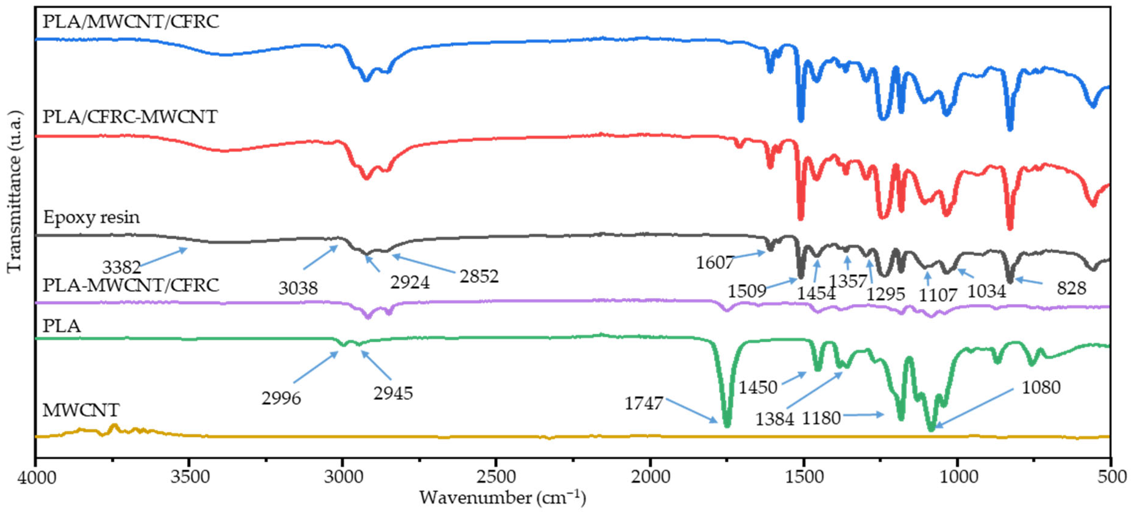
Polymers reinforced and nonreinforced with MWCNTs were evaluated. In the PLA-MWCNT/CFRC, PLA/CFRC-MWCNT, and PLA/MWCNT/CFRC samples, the reinforced matrix was evaluated. This approach allowed for an accurate assessment of the interactions between the matrix and the MWCNTs, while maintaining the original nomenclature to facilitate the comparison between the obtained results and the composition of the samples. The FTIR spectra of the MWCNT, PLA, resin, and polymer nano-reinforced samples are shown in Figure 7. The PLA bands were located at 2996; 2945 cm−1, corresponding to the asymmetric/symmetric stretching of the C-H; 1747 cm−1, with the stretching vibration of the C=O bond of the carboxyl group; 1450; 1384 cm−1, indicating the asymmetric/symmetric bending of C-H; and 1180 cm−1−1080 cm−1, corresponding to the stretching vibration group C-O [49,50,51]. As can be seen in the FTIR spectra, both the PLA spectrum and the PLA-MWCNT/CFRC spectrum presented similar peaks. The shift in the asymmetric/symmetric C-H stretching band from 2.996 and 2.945 cm−1 to 2.917 and 2.844 cm−1 indicated the interaction between PLA and carbon nanotubes [52,53].
FTIR measurements of the different nanocomposites were taken to determine the changes and interactions between the MWCNTs and the epoxy resin. In the spectrum of the epoxy resin, a band width of 3378 cm−1, corresponding to the hydroxyl group (O-H), could be observed. In addition, peaks were identified at 3038 cm−1, corresponding to the C-H tension of the epoxy resin ring’s methyl group (CH2). Vibrations were also observed at 2924 and 2852 cm−1, which were attributed to the asymmetric and symmetric stretching of the methyl group (CH3). The 1607 and 1509 cm−1 peaks corresponded to the C=C aromatic and benzene rings’ C-C stretching, respectively. Likewise, bands at 1454 and 1357 cm−1 were identified, corresponding to the asymmetric bending vibration and symmetry of the methyl group (CH3). Similarly, peaks at 1295, 1107, 1034, and 828 cm−1 were attributed to the stretching of the C-C, C-O, and C-O-C of the ether groups and, finally, the C-O-C of the oxirane group, respectively [54,55]. The spectra of the different nanocomposites—PLA/CFRC-MWCNT and PLA/MWCNT/CFRC—presented similar bands, with variations in the intensity of the peaks; this change in intensity was reported to be the interaction between the MWCNT and the epoxy resin [44,56].

3.4. Thermal Analysis (TGA-DSC)

The thermal properties of the MWCNT-reinforced polymeric materials were evaluated by thermogravimetric analysis (TGA) and differential scanning calorimetry (DSC), as displayed in Figure 8. TGA revealed changes in the properties of the base materials. In general, all of them revealed decreases in their properties, as observed in Figure 8a. In the case of PLA and the PLA-MWCNT/CFRC structural composite, a 3.04% decrease in the thermal stability of PLA was observed after the incorporation of MWCNTs. In addition, both materials experienced a weight loss greater than 97% with respect to the reinforced matrix. In the case of epoxy resin, both PLA/CFRC-MWCNT and PLA/MWCNT/CFRC demonstrated similar behavior, with a decrease in their thermal properties. This behavior was attributed to the formation of an interface when incorporating carbon nanotubes, which affected the creation of polymer chains [57]. It was observed that the PLA/CFRC-MWCNT sample presented a significant reduction of 19.28% in the degradation temperature, suggesting the lack of good integration of the nanotubes in the polymeric matrix. Meanwhile, the PLA/MWCNT/CFRC sample presented better interaction between the resin and the nanotubes, with a 5.04% reduction in the degradation temperature; in this case, the carbon nanotubes acted as a thermal barrier, delaying the degradation process thanks to the way in which they were incorporated into the structural composite. However, all composites exhibited a reduction in the initial and maximum degradation temperatures compared to pure resin. This change can be seen in Table 3, alongside the characteristic parameters of the degradation start temperature at 5%, the maximum degradation temperature, the percentage of mass lost during the test, and the residues obtained at 500 °C for each material.
The glass transition temperature (Tg), cold crystallization (Tcc), and melting (Tm) of these materials were evaluated by DSC, as presented in Figure 8b. The incorporation of MWCNTs into the polymers resulted in a decrease in temperature in most of the composites, except for PLA/MWCNT/CFRC. The Tg for the different nanocomposites is presented in Figure 8b, where a 7.25% reduction in PLA-MWCNT/CFRC with respect to PLA and a 15.15% decrease in PLA/CFRC-MWCNT with respect to epoxy resin can be observed; this could be attributed to the fact that MWCNTs decreased the cross-linking density [58]. On the other hand, there was a 3.12% increase in PLA/MWCNT/CFRC compared to the base material, which was caused by the incorporation method used for the MWCNTs.
In the TGA, it was observed that the PLA-MWCNT/CFRC composite maintained a thermal stability higher than 375 °C, but reduced compared to pure PLA by less than 1%. This slight decrease could be attributed to the poor cross-linking and branching of the polymer chains [19,21,46,59] or the high thermal conductivity of the MWCNTs, which generated localized temperatures in the nanotube agglomerations. These hot zones accelerated premature degradation at the interface between PLA and MWCNTs [53]. Experimental results showed that the PLA-MWCNT/CFRC composite had a lower percentage of weight loss compared to pure PLA at the same temperatures. This could be attributed to the presence of MWCNTs, which contributed to the structural integrity of the composite during thermal degradation [60]. A higher residue was also present after combustion. This increase in residue was attributed to the high thermal resistance and non-combustible nature of MWCNTs, which remained as residue after PLA decomposition. In the case of the composites with an epoxy matrix, the curves revealed decreasing degradation temperatures in the nanocomposites, attributed to the generation of an interface when incorporating the carbon nanotubes, which in turn affected the formation of polymeric chains [57].
Regarding the values of Tg, Tcc, and Tm presented in the DSC curve between PLA and PLA-MWCNT/CFRC, a decrease was observed, caused by the incorporation of MWCNTs, which indicated an interaction between PLA and MWCNTs. This decrease could be attributed to the restricted mobility of PLA macromolecular chains due to interactions with MWCNTs. The presence of nanotubes acted as a plasticizing agent by interfering with the movement of chain segments, thereby reducing the glass transition temperature [7,21,61]. On the other hand, the addition of MWCNTs generally did not affect the melting temperature of PLA, largely due to the crystalline regions of the polymer itself, which were not affected by the presence of nanotubes [62], with a decrease percentage of less than 0.55% compared to PLA at 172 °C. In the case of PLA/CFRC-MWCNT, a decrease in the glass transition temperature was observed, an effect related to the interaction of the nanotubes in the resin. Unlike PLA/MWCNT/CFRC, this sample presented an increase in the glass transition temperature due to the methodology used to incorporate MWCNTs, creating a thermal barrier in the process. In addition to having the best thermal behavior out of the nanocomposites with an epoxy matrix, based on published studies, an increase in the MWCNT content could improve the thermal stability and raise the glass transition temperature of nanocomposites [27,54,55].

3.5. Mechanical Properties of the Nanocomposites

The mechanical properties of the nanocomposites were determined through tension tests using the ASTM D638 standard [34]. Figure 9a presents the stress vs. strain curves of PLA/CFRC, PLA-MWCNT/CFRC, PLA/CFRC-MWCNT, and PLA/CFRC/MWCNT at 0.1 wt % MWCNT using different nanofilling techniques in the composite. These techniques included fusion-blending PLA and carbon nanotubes, the dispersion of carbon nanotubes in epoxy resin using ultrasound waves, and spray-coating MWCNTs onto PLA and CFRC interlayers, as described in the section covering the synthesis of MWCNTs and the manufacturing of composite materials with MWCNT fillers. This curve demonstrated improvements in the mechanical properties, both in terms of tensile strength and elastic modulus. This indicated that the incorporation of MWCNTs contributed significantly to improving the mechanical performance. This was because the multi-walled carbon nanotubes reinforced the matrix by distributing stress, which facilitated load transfer from the matrix to the nanotubes. Furthermore, the interaction between the matrix (PLA or epoxy resin) and the nanotubes improved adhesion, acting as a bridge between cracks, reducing creep and crack propagation. The nanotubes also contributed to elongation in the elastic zone of the material, improving its toughness and energy absorption capacity [63,64,65]. The best performance was observed when using the epoxy resin dispersion method. The bar graphs of tensile strength displayed in Figure 9b indicate that the PLA/CFRC/MWCNT nanocomposite exhibited a decrease compared to PLA/CFRC. In this investigation, the elastic modulus of the PLA/CFRC-MWCNT nanocomposite showed a significant improvement from 20.65 ± 0.753 GPa to 24.57 ± 0.628 GPa compared to PLA/CFRC, as seen in the bar graph in Figure 9c. The mechanical properties in these materials were particularly relevant because the objective of these nanocomposites was to emulate the mechanical properties of bone [66,67,68,69]. The ultimate strength and elastic modulus of bone were in a similar range compared to the other materials used in this work, as presented in Figure 9b,c, which makes these nanocomposites suitable for biomedical applications, such as implants or prostheses.
During the tension tests, the specimens presented delamination between the PLA and CFRC plates, a characteristic failure of the composites. The breaks in the PLA plates occurred with a 45° orientation, following the orientation of the printing filaments. Furthermore, in all the specimens, perpendicular breakage occurred in the direction of the load, close to the upper or lower jaw. Concerning the type of behavior of the material, we obtained similar results to a previous study that presented the typical behavior of a fragile material [29,70,71]. The PLA/CFRC-MWCNT nanocomposite exhibited the best mechanical properties, due to its high degree of dispersion. This was achieved through minimal nanotube agglomeration and a more homogeneous distribution in the matrix [55,72]. Instead, the PLA/CFRC/MWCNT nanocomposite presented a decrease in its mechanical properties, which could be attributed to the aggregation of the carbon nanotubes, causing a lack of contact between the MWCNTs and the epoxy resin, which, in turn, caused a decrease in the mechanical properties [71]. All nanocomposites were found to have values in the elastic range of cortical bone, which is between 15.00 and 23.40 GPa, contrary to the maximum stress, where the nanocomposites presented a value two times greater than that reported for the ultimate resistance of cortical bone, which is between 107 and 146 MPa [29,66,67,68,69,73].
The nanocomposite with the lowest mechanical properties was PLA/MWCNT/CFRC. This material featured interlayers coated with carbon nanotubes, which generated a concentration of stresses at the interfaces of the laminate. This concentration could result in a weak interface between the resin and the fiber or between the resin and the 3D-printed laminate, causing premature failures in the structure due to poor adhesion between the components. The PLA-MWCNT/CFRC nanocomposite featured carbon nanotubes embedded in the PLA matrix, which limited its effective interaction with the other components, such as the fiber and the resin. For this reason, the transfer of stresses between the materials was not efficient. This lack of adequate interaction implied that the carbon nanotubes did not contribute significantly to improving the overall mechanical properties of the composite material. The PLA/CFRC-MWCNT nanocomposite featured a uniform dispersion of carbon nanotubes in the resin matrix, which was spread throughout the composite. This distribution allowed for a higher coating volume on the structural material, resulting in a significant improvement of its mechanical properties. Thanks to this dispersion, carbon nanotubes effectively reinforced the interfaces between the resin, the fiber, and the 3D-printed laminate, improving the transfer of stresses through the composite.
Nanocomposites with PLA, CFRC, and MWCNT materials, fabricated by different methods, presented several material alternatives with potential for prosthetic applications. The incorporation of carbon nanotubes (MWCNTs) into these composites significantly improved their mechanical properties, such as their elastic modulus and tensile strength. This is particularly relevant to reduce the stiffness discrepancy between implanted materials and natural bone, a critical factor for biomechanical integration [74].

3.6. Morphological Analysis

Figure 10 presents SEM images of the fractured surface after tensile testing the PLA/CFRC composite and the carbon nanotube-reinforced composites (PLA-MWCNT/CFRC, PLA/CFRC-MWCNT, and PLA/MWCNT/CFRC). In Figure 10a, one can observe that the separation between the fibers and the matrix was due to a failure at the interface along the fiber. This phenomenon occurs when the stresses between the fiber and the matrix exceed the interface strength, causing the fiber to detach. Both the matrix and the fiber contribute to the stress concentration in this zone, which causes the degradation of the matrix and its subsequent detachment after the propagation of fractures on the reinforcement surface [75]. Figure 10b presents carbon nanotubes (MWCNTs) embedded in the PLA matrix as a result of the tensile test, due to the fabrication process employed, which consisted of melt-blending PLA and MWCNTs. This method encapsulated the MWCNTs, allowing them to be observed in this manner [76]. Figure 10c displays a multi-walled carbon nanotube (MWCNT) embedded in an epoxy resin matrix. The image reveals that part of the nanotube is separated from the matrix, while another part maintains direct contact due to interfacial adhesion. This clearly illustrates the interaction and adhesion between the MWCNT and the epoxy resin in this structural composite [75,76], which is a result of the dispersion of the MWCNTs in the epoxy resin. Figure 10d shows the brittle nature of the structural composite, evidencing the absence of plastic deformation. The fracturing of the carbon fiber and the separation of the resin can be observed due to the load applied during the tensile test, which exceeded the resistance of both the matrix and the fiber, causing a brittle fracture [75,77,78].

3.7. Cell Viability Assay

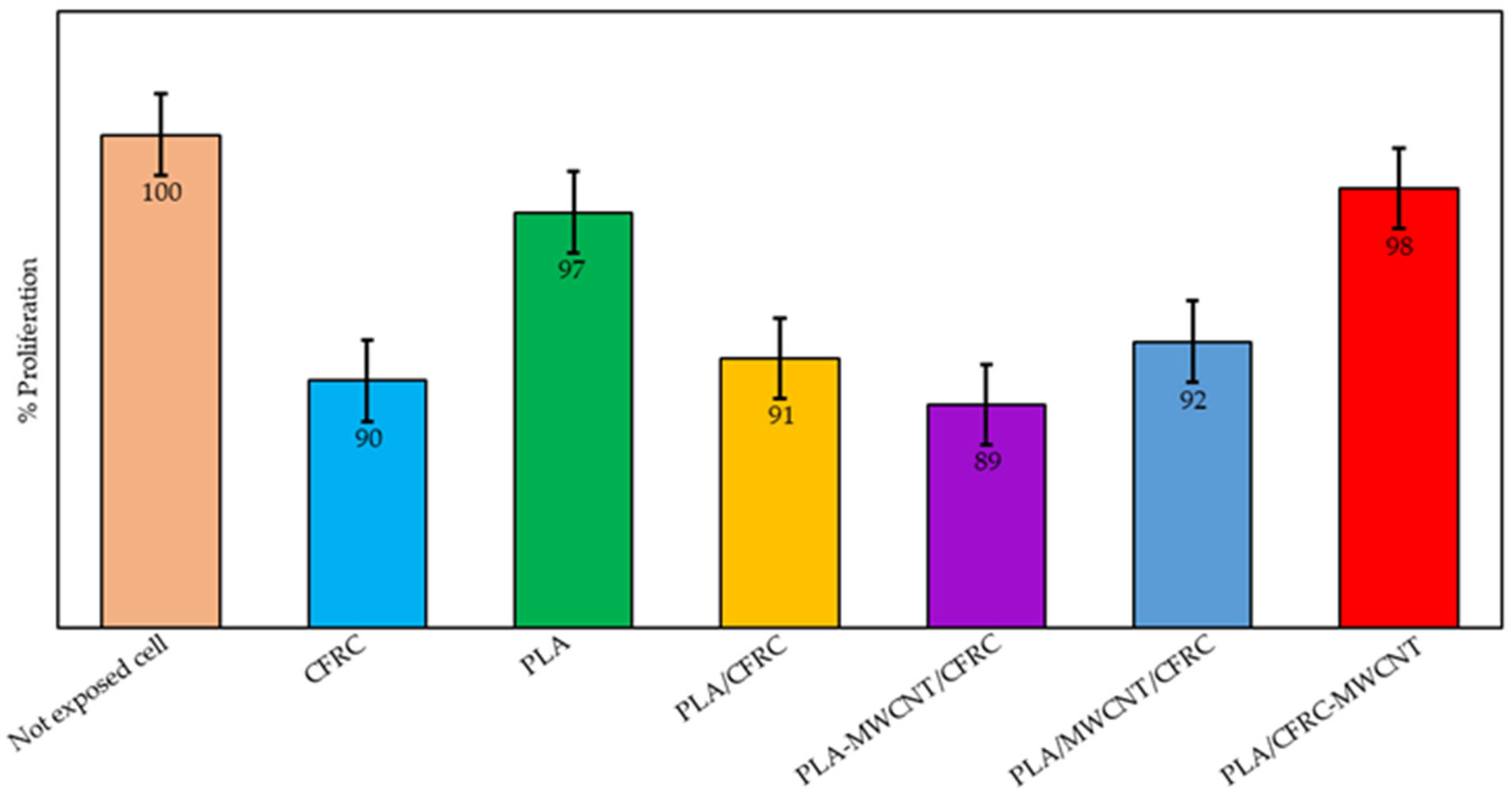
Viability in primary human peripheral blood mononuclear cells (lymphocytes and monocytes) exposed to the PLA/CFRC, PLA/CFRC-MWCNT, PLA-MWCNT/CFRC, PLA/MWCNT/CFRC, CFRC, and PLA samples was assessed using the MTT assay. This indirect assay measures mitochondrial function by determining the activity of the mitochondrial enzyme succinate dehydrogenase, which reduces the tetrazolium salt of MTT to form formazan, whereby higher concentrations of formazan indicate a greater proportion of viable cells [79]. According to the results of this study (Figure 11), none of the samples showed significant toxicity as per ISO standard 10933-5, since they all maintained a cell growth rate above 80%. The PLA/CFRC-MWCNT sample indicated the least alteration in cell growth (98 ± 2%), while the PLA-MWCNT/CFRC sample exhibited the highest reduction in cell replication, with an ~11% decrease in cell growth. The other samples did not reduce cell proliferation by more than 10%, with no significant difference (ANOVA, p > 0.05) between the samples and normal cell growth.
The results we observed support the idea that PLA is biocompatible and non-toxic to PBMCs when assessed using the MTT assay [80]. PLA is recognized as a versatile, biocompatible, and biodegradable polymer that has received FDA approval [81]. Similarly, the biocompatibility of the PDLLA films was verified, supporting these findings [82]. Our cell viability results with lymphocytes were comparable to those of previous studies. However, the observed decrease in viability across all samples, including PLA, might have been due to the adhesion of monocytes to the surface [83]. Consequently, when the exposed cells were removed from the samples, some might have remained attached to the surface [84,85].
For the samples containing carbon fibers (PLA/CFRC, CFRC), no adverse effects on PBMCs were observed, with most samples showing cell viability above ~90%. These findings were similar to those of previous studies that analyzed the biocompatibility of carbon fibers in human MG-63 osteoblastic cells [86]. The aforementioned study noted a slight decrease in cell viability after 24 h of exposure to carbon fibers, but cell proliferation was efficient after 7 days of incubation. Similarly, our previous study [29] indicated that PLA, CFRC, and PLA/CFRC materials are non-toxic to PBMCs, demonstrating consistent and reproducible results.
For samples containing MWCNTs (PLA/CFRC-MWCNT, PLA-MWCNT/CFRC, and PLA/MWCNT/CFRC), the literature indicates that structures with pure or conjugated MWCNTs do not inhibit cell growth over 24 h of exposure. For example, research on human lung squamous cells A549 [87], human peripheral blood cells (PBMCs), and rat adrenal medulla pheochromocytoma cells PC12 [88] confirmed biocompatibility. However, it is widely agreed that the response depends on the concentration of MWCNTs in the sample, with significant decreases in cell growth observed at concentrations above 2 μg/mL [88]. It was found that concentrations up to 40 μg/mL were required to achieve toxicity, as PBMC viability was not affected at 30 μg/mL after 24 h [89]. In this study, the samples contained an average of ~0.1% by weight of MWCNTs, ensuring their cellular biocompatibility.

4. Conclusions

A family of nanocomposites based on PLA, epoxy resin, carbon fibers, and MWCNTs was developed. Carbon nanotubes were synthesized by spray-pyrolysis and incorporated into the matrix (PLA and epoxy resin) at 0.1% wt using three techniques: resin dispersion, spray-coating, and fusion-blending. The objectives were to evaluate their interaction, determine the material’s mechanical properties, and ensure biological compatibility.
Five synthesis iterations were evaluated by Raman analysis, obtaining an average ID/IG ratio of 1.44 ± 0.089, indicating high crystallinity along with the presence of defects in the MWCNTs.
The interaction of multi-walled carbon nanotubes with PLA and epoxy resin matrices was analyzed by FTIR. The shift in the asymmetric and symmetric C-H stretching bands in PLA-MWCNT/CFRC from 2.996 and 2.945 cm−1 to 2.917 and 2.844 cm−1 evidenced the interaction between PLA and carbon nanotubes. Furthermore, the spectra of the PLA/CFRC-MWCNT and PLA/MWCNT/CFRC nanocomposites showed similar bands, with variations in the peak intensities.
SEM analysis allowed us to examine the morphology of the MWCNTs and their distribution within the matrices. The average diameters and their standard deviations for synthesis iterations 1, 2, 3, 4, and 5 were 150 ± 24 nm, 125 ± 21 nm, 167 ± 20 nm, 147 ± 23 nm, and 142 ± 19 nm, respectively. Furthermore, the average length of the nanotubes in this study was 14,407 ± 2869 nm, making them excellent candidates for use as reinforcements in polymer matrices.
The TGA and DSC analyses allowed us to evaluate the thermal properties of the material, analyzing its thermal stability and the phase transition Tg, Tcc, and Tm values. It was observed that the incorporation of MWCNTs into the different nanocomposites generated thermal variations, mainly manifested in a decrease in temperature. However, all the composites showed thermal stability above 338 °C. This temperature decrease did not pose any disadvantage to their use.
Tensile tests were performed to determine the mechanical properties of the material, evaluating its ultimate strength and elastic modulus. The results indicated that the composites exhibited an elastic modulus comparable to that of bone and a tensile strength twice as high as that of bone. The elastic modulus is a crucial parameter, as it measures the stiffness of a material, a key factor in considering applications in prosthetics. The PLA/CFRC-MWCNT nanocomposite emerged as the best candidate, with an elastic modulus of 24.57 ± 0.628 GPa, presenting a reduction in the stiffness difference between the implanted material and the bone.
The biocompatibility of the material was evaluated using in vitro tests and a cell viability assay. The cell viability study confirmed that the developed products were non-toxic, ensuring their biological compatibility. The results showed cell viability of over 89% for the different composites. The best candidate in terms of cell viability was PLA/CFRC-MWCNT, with a value of 98%.
Each combination of nano-reinforced composite materials with MWCNTs showed specific variations in mechanical performance, facilitating their adaptation to different applications according to requirements. Furthermore, the biocompatibility and thermal stability of the composites were confirmed, supporting their viability for biomedical applications. This study developed of a family of composites based on PLA, resin, MWCNTs, and carbon fiber, with great potential for use in the biomedical field. Future research will focus on fatigue testing, in vivo evaluation, and shear testing, with the goal of more comprehensively assessing the behavior of these materials under more realistic and specific conditions for biomedical applications.

Author Contributions

J.A.P.-G.: writing—original draft, validation, methodology, and investigation. C.V.-S.: writing—review and editing, supervision, methodology, investigation, and conceptualization. L.J.V.-G.: writing—review and editing, supervision, methodology, investigation, formal analysis, and conceptualization. E.A.-Z.: investigation and formal analysis. A.Z.-L.: resources and formal analysis. B.T.-N.: resources and formal analysis. O.A.M.-C.: supervision and methodology. Y.G.-P.: writing—review and editing, validation, supervision, methodology, conceptualization, and project administration. All authors have read and agreed to the published version of the manuscript.

Funding

Partial APCs was support by the postgraduate program of Master in Engineering and Manufacturing Processing, from the Faculty of Engineering Sciences and Technology, Autonomous University of Baja California, Valle de Las Palmas, Tijuana, Baja California, Mexico.

Data Availability Statement

Data were included in the manuscript.

Acknowledgments

Figure 1, Figure 2, Figure 3 and Figure 4, were partially created by BioRender. Paz, J. (2025) https://BioRender.com/p86jijz. Agreements numbers: Figure 1 (AW282S6C5H), Figure 2 (EH282S6C8F), Figure 3 (OS282S6CBL) and Figure 4 (QA282S6CEA).

Conflicts of Interest

The authors declare no conflicts of interest.

References

  1. Sheoran, A.J.; Kumar, H.; Arora, P.K.; Moona, G. Bio-Medical Applications of Additive Manufacturing: A Review. Procedia Manuf. 2020, 51, 663–670. [Google Scholar] [CrossRef]
  2. Saeed, K.; McIlhagger, A.; Harkin-Jones, E.; McGarrigle, C.; Dixon, D.; Ali Shar, M.; McMillan, A.; Archer, E. Characterization of Continuous Carbon Fibre Reinforced 3D Printed Polymer Composites with Varying Fibre Volume Fractions. Compos. Struct. 2022, 282, 115033. [Google Scholar] [CrossRef]
  3. Wang, X.; Jiang, M.; Zhou, Z.; Gou, J.; Hui, D. 3D Printing of Polymer Matrix Composites: A Review and Prospective. Compos. Part B Eng. 2017, 110, 442–458. [Google Scholar] [CrossRef]
  4. Katoozian, H.; Davy, D.T.; Arshi, A.; Saadati, U. Material Optimization of Femoral Component of Total Hip Prosthesis Using Fiber Reinforced Polymeric Composites. Med. Eng. Phys. 2001, 23, 505–511. [Google Scholar] [CrossRef]
  5. Agarwal, T.; Chiesa, I.; Presutti, D.; Irawan, V.; Vajanthri, K.Y.; Costantini, M.; Nakagawa, Y.; Tan, S.A.; Makvandi, P.; Zare, E.N.; et al. Recent Advances in Bioprinting Technologies for Engineering Different Cartilage-Based Tissues. Mater. Sci. Eng. C 2021, 123, 112005. [Google Scholar] [CrossRef]
  6. Mittal, G.; Rhee, K.Y.; Mišković-Stanković, V.; Hui, D. Reinforcements in Multi-Scale Polymer Composites: Processing, Properties, and Applications. Compos. Part B Eng. 2018, 138, 122–139. [Google Scholar] [CrossRef]
  7. Lee, J.H.; Park, S.H.; Kim, S.H.; Ito, H. Replication and Surface Properties of Micro Injection Molded PLA/MWCNT Nanocomposites. Polym. Test. 2020, 83, 106321. [Google Scholar] [CrossRef]
  8. Yang, C.; Chen, S.; Wang, J.; Zhu, T.; Xu, G.; Chen, Z.; Ma, X.; Li, W. A Facile Electrospinning Method to Fabricate Polylactide/Graphene/MWCNTs Nanofiber Membrane for Tissues Scaffold. Appl. Surf. Sci. 2016, 362, 163–168. [Google Scholar] [CrossRef]
  9. Yang, L.; Li, S.; Zhou, X.; Liu, J.; Li, Y.; Yang, M.; Yuan, Q.; Zhang, W. Effects of Carbon Nanotube on the Thermal, Mechanical, and Electrical Properties of PLA/CNT Printed Parts in the FDM Process. Synth. Met. 2019, 253, 122–130. [Google Scholar] [CrossRef]
  10. Sanusi, O.M.; Benelfellah, A.; Terzopoulou, Z.; Bikiaris, D.N.; Aït Hocine, N. Properties of Polylactide Reinforced with Montmorillonite/Multiwalled Carbon Nanotube Hybrid. Mater. Today Proc. 2021, 47, 3247–3250. [Google Scholar] [CrossRef]
  11. Cobos, C.; Conejero, A.; Fenollar, O.; Ferrándiz, S. Influence of the Addition of 0.5 and 1% in Weight of Multi-Wall Carbon Nanotubes (MWCNTs) in Poly-Lactic Acid (PLA) for 3D Printing. Procedia Manuf. 2019, 41, 875–881. [Google Scholar] [CrossRef]
  12. Chaudhry, M.S.; Czekanski, A.; Zhu, Z.H. Characterization of Carbon Nanotube Enhanced Interlaminar Fracture Toughness of Woven Carbon Fiber Reinforced Polymer Composites. Int. J. Mech. Sci. 2017, 131–132, 480–489. [Google Scholar] [CrossRef]
  13. Urtekin, G.; Aytac, A. The Effects of Multi-Walled Carbon Nanotube Additives with Different Functionalities on the Properties of Polycarbonate/Poly (Lactic Acid) Blend. J. Polym. Res. 2021, 28, 180. [Google Scholar] [CrossRef]
  14. Rathinavel, S.; Priyadharshini, K.; Panda, D. A Review on Carbon Nanotube: An Overview of Synthesis, Properties, Functionalization, Characterization, and the Application. Mater. Sci. Eng. B Solid-State Mater. Adv. Technol. 2021, 268, 115095. [Google Scholar] [CrossRef]
  15. Mittal, G.; Dhand, V.; Rhee, K.Y.; Park, S.J.; Lee, W.R. A Review on Carbon Nanotubes and Graphene as Fillers in Reinforced Polymer Nanocomposites. J. Ind. Eng. Chem. 2015, 21, 11–25. [Google Scholar] [CrossRef]
  16. Annu, A.; Bhattacharya, B.; Singh, P.K.; Shukla, P.K.; Rhee, H.W. Carbon Nanotube Using Spray Pyrolysis: Recent Scenario. J. Alloys Compd. 2017, 691, 970–982. [Google Scholar] [CrossRef]
  17. Ebbesen, T.W.; Lezec, H.J.; Hiura, H.; Bennett, J.W.; Ghaemi, H.F.; Thio, T. Electrical Conductivity of Individual Carbon Nanotubes. Nature 1996, 382, 54–56. [Google Scholar] [CrossRef]
  18. Fenta, E.W.; Mebratie, B.A. Advancements in Carbon Nanotube-Polymer Composites: Enhancing Properties and Applications through Advanced Manufacturing Techniques. Heliyon 2024, 10, e36490. [Google Scholar] [CrossRef]
  19. Cardona Salcedo, M.A.; Oropeza Guzmán, M.T.; Moreno Grijalva, G.I.; Zizumbo López, A.; Paz González, J.A.; Gochi Ponce, Y. Polylactic Acid/Multi Walled Carbon Nanotubes (PLA/MWCNT) Nanocomposite for 3D Printing of Medical Devices. Rev. Cienc. Tecnológicas 2021, 4, 388–398. [Google Scholar] [CrossRef]
  20. Aguilar-Elguézabal, A.; Antúnez, W.; Alonso, G.; Delgado, F.P.; Espinosa, F.; Miki-Yoshida, M. Study of Carbon Nanotubes Synthesis by Spray Pyrolysis and Model of Growth. Diam. Relat. Mater. 2006, 15, 1329–1335. [Google Scholar] [CrossRef]
  21. Luo, J.; Wang, H.; Zuo, D.; Ji, A.; Liu, Y. Research on the Application of MWCNTs/PLA Composite Material in the Manufacturing of Conductive Composite Products in 3D Printing. Micromachines 2018, 9, 635. [Google Scholar] [CrossRef]
  22. Mai, F.; Deng, H.; Tu, W.; Chankajorn, S.; Fu, Q.; Bilotti, E.; Peijs, T. Oriented Poly(Lactic Acid)/Carbon Nanotube Composite Tapes with High Electrical Conductivity and Mechanical Properties. Macromol. Mater. Eng. 2015, 300, 1257–1267. [Google Scholar] [CrossRef]
  23. Aly, K.; Li, A.; Bradford, P.D. Strain Sensing in Composites Using Aligned Carbon Nanotube Sheets Embedded in the Interlaminar Region. Compos. Part A Appl. Sci. Manuf. 2016, 90, 536–548. [Google Scholar] [CrossRef]
  24. Zakaria, M.R.; Abdul Kudus, M.H.; Akil, H.M.; Mohd Thirmizir, M.Z. Comparative Study of Graphene Nanoparticle and Multiwall Carbon Nanotube Filled Epoxy Nanocomposites Based on Mechanical, Thermal and Dielectric Properties. Compos. Part B Eng. 2017, 119, 57–66. [Google Scholar] [CrossRef]
  25. Villmow, T.; Pötschke, P.; Pegel, S.; Häussler, L.; Kretzschmar, B. Influence of Twin-Screw Extrusion Conditions on the Dispersion of Multi-Walled Carbon Nanotubes in a Poly(Lactic Acid) Matrix. Polymer 2008, 49, 3500–3509. [Google Scholar] [CrossRef]
  26. Szatkowski, P.; Czechowski, L.; Gralewski, J.; Szatkowska, M. Mechanical Properties of Polylactide Admixed with Carbon Nanotubes or Graphene Nanopowder. Materials 2021, 14, 5955. [Google Scholar] [CrossRef] [PubMed]
  27. Kumar, A.; Ghosh, P.K.; Yadav, K.L.; Kumar, K. Thermo-Mechanical and Anti-Corrosive Properties of MWCNT/Epoxy Nanocomposite Fabricated by Innovative Dispersion Technique. Compos. Part B Eng. 2017, 113, 291–299. [Google Scholar] [CrossRef]
  28. Shchegolkov, A.V.; Shchegolkov, A.V.; Kaminskii, V.V.; Iturralde, P.; Chumak, M.A. Advances in Electrically and Thermally Conductive Functional Nanocomposites Based on Carbon Nanotubes. Polymers 2024, 17, 71. [Google Scholar] [CrossRef]
  29. Paz-González, J.A.; Velasco-Santos, C.; Villarreal-Gómez, L.J.; Alcudia-Zacarias, E.; Olivas-Sarabia, A.; Cota-Leal, M.A.; Flores-López, L.Z.; Gochi-Ponce, Y. Structural Composite Based on 3D Printing Polylactic Acid/Carbon Fiber Laminates (PLA/CFRC) as an Alternative Material for Femoral Stem Prosthesis. J. Mech. Behav. Biomed. Mater. 2023, 138, 105632. [Google Scholar] [CrossRef]
  30. Mohammadi Zerankeshi, M.; Bakhshi, R.; Alizadeh, R. Polymer/Metal Composite 3D Porous Bone Tissue Engineering Scaffolds Fabricated by Additive Manufacturing Techniques: A Review. Bioprinting 2022, 25, e00191. [Google Scholar] [CrossRef]
  31. Gimenes Benega, M.A.; Silva, W.M.; Schnitzler, M.C.; Espanhol Andrade, R.J.; Ribeiro, H. Improvements in Thermal and Mechanical Properties of Composites Based on Epoxy-Carbon Nanomaterials—A Brief Landscape. Polym. Test. 2021, 98, 107180. [Google Scholar] [CrossRef]
  32. Zhang, H.; Kuwata, M.; Bilotti, E.; Peijs, T. Integrated Damage Sensing in Fibre-Reinforced Composites with Extremely Low Carbon Nanotube Loadings. J. Nanomater. 2015, 2015, 785834. [Google Scholar] [CrossRef]
  33. Rodríguez-González, J.A.; Rubio-González, C.; Jiménez-Mora, M.; Ramos-Galicia, L.; Velasco-Santos, C. Influence of the Hybrid Combination of Multiwalled Carbon Nanotubes and Graphene Oxide on Interlaminar Mechanical Properties of Carbon Fiber/Epoxy Laminates. Appl. Compos. Mater. 2018, 25, 1115–1131. [Google Scholar] [CrossRef]
  34. ASTM D638-14; Standard Test Method for Tensile Properties of Plastics. ASTM International: West Conshohocken, PA, USA, 2016; Volume 82, pp. 1–15. [CrossRef]
  35. Molaae, N.; Mosayebi, G.; Pishdadian, A.; Ejtehadifar, M.; Ganji, A. Evaluating the Proliferation of Human PeripheralBlood Mononuclear Cells Using MTT Assay. Int. J. Basic Sci. Med. 2017, 2, 25–28. [Google Scholar] [CrossRef]
  36. Holland, M.; Cunningham, R.; Seymour, L.; Kleinsteuber, K.; Cunningham, A.; Patel, T.; Manos, M.; Brennick, R.; Zhou, J.; Hodi, F.S.; et al. Separation, Banking, and Quality Control of Peripheral Blood Mononuclear Cells from Whole Blood of Melanoma Patients. Cell Tissue Bank. 2018, 19, 783–790. [Google Scholar] [CrossRef] [PubMed]
  37. Arul Xavier Stango, S.; Vijayalakshmi, U. Synthesis and Characterization of Hydroxyapatite/Carboxylic Acid Functionalized MWCNTS Composites and Its Triple Layer Coatings for Biomedical Applications. Ceram. Int. 2019, 45, 69–81. [Google Scholar] [CrossRef]
  38. Bokobza, L.; Zhang, J. Raman Spectroscopic Characterization of Multiwall Carbon Nanotubes and of Composites. Express Polym. Lett. 2012, 6, 601–608. [Google Scholar] [CrossRef]
  39. Li, Z.; Deng, L.; Kinloch, I.A.; Young, R.J. Raman Spectroscopy of Carbon Materials and Their Composites: Graphene, Nanotubes and Fibres. Prog. Mater. Sci. 2023, 135, 101089. [Google Scholar] [CrossRef]
  40. Alotaibi, M.S.; Almousa, N.H.; Asaker, M.A.; Alkasmoul, F.S.; Khdary, N.H.; Khayyat, M. Morphological: Optical, and Mechanical Characterizations of Non-Activated and Activated Nanocomposites of SG and MWCNTs. Crystals 2021, 11, 1280. [Google Scholar] [CrossRef]
  41. Garg, P.; Singh, B.P.; Kumar, G.; Gupta, T.; Pandey, I.; Seth, R.K.; Tandon, R.P.; Mathur, R.B. Effect of Dispersion Conditions on the Mechanical Properties of Multi-Walled Carbon Nanotubes Based Epoxy Resin Composites. J. Polym. Res. 2011, 18, 1397–1407. [Google Scholar] [CrossRef]
  42. Li, H.; Wang, G.; Wu, Y.; Jiang, N.; Niu, K. Functionalization of Carbon Nanotubes in Polystyrene and Properties of Their Composites: A Review. Polymers 2024, 16, 770. [Google Scholar] [CrossRef]
  43. Ramezani, M.; Dehghani, A.; Sherif, M.M. Carbon Nanotube Reinforced Cementitious Composites: A Comprehensive Review. Constr. Build. Mater. 2022, 315, 125100. [Google Scholar] [CrossRef]
  44. Nimbagal, V.; Banapurmath, N.R.; Sajjan, A.M.; Patil, A.Y.; Ganachari, S.V. Studies on Hybrid Bio-Nanocomposites for Structural Applications. J. Mater. Eng. Perform. 2021, 30, 6461–6480. [Google Scholar] [CrossRef]
  45. Tapasztó, L.; Kertész, K.; Vértesy, Z.; Horváth, Z.E.; Koós, A.A.; Osváth, Z.; Sárközi, Z.; Darabont, A.; Biró, L.P. Diameter and Morphology Dependence on Experimental Conditions of Carbon Nanotube Arrays Grown by Spray Pyrolysis. Carbon 2005, 43, 970–977. [Google Scholar] [CrossRef]
  46. Yoon, J.T.; Lee, S.C.; Jeong, Y.G. Effects of Grafted Chain Length on Mechanical and Electrical Properties of Nanocomposites Containing Polylactide-Grafted Carbon Nanotubes. Compos. Sci. Technol. 2010, 70, 776–782. [Google Scholar] [CrossRef]
  47. López-Barroso, J.; Martínez-Hernández, A.L.; Rivera-Armenta, J.L.; Velasco-Santos, C. Multidimensional Nanocomposites of Epoxy Reinforced with 1D and 2D Carbon Nanostructures for Improve Fracture Resistance. Polymers 2018, 10, 281. [Google Scholar] [CrossRef]
  48. Dubyey, L.; Ukrainczyk, N.; Yadav, S.; Izadifar, M.; Schneider, J.J.; Koenders, E. Carbon Nanotubes and Nanohorns in Geopolymers: A Study on Chemical, Physical and Mechanical Properties. Mater. Des. 2024, 240, 112851. [Google Scholar] [CrossRef]
  49. Mofokeng, J.P.; Luyt, A.S.; Tábi, T.; Kovács, J. Comparison of Injection Moulded, Natural Fibre-Reinforced Composites with PP and PLA as Matrices. J. Thermoplast. Compos. Mater. 2012, 25, 927–948. [Google Scholar] [CrossRef]
  50. Yu, S.; Xiang, H.; Zhou, J.; Zhu, M. Enhanced Flame-Retardant Performance of Poly (Lactic Acid) (PLA) Composite by Using Intrinsically Phosphorus-Containing PLA. Prog. Nat. Sci. Mater. Int. 2018, 28, 590–597. [Google Scholar] [CrossRef]
  51. Chieng, B.W.; Ibrahim, N.A.; Zin, W.; Yunus, W.; Hussein, M.Z. Poly(Lactic Acid)/Poly(Ethylene Glycol) Polymer Nanocomposites: Effects of Graphene Nanoplatelets. Polymers 2014, 6, 93–104. [Google Scholar] [CrossRef]
  52. Wei, X.P.; Luo, Y.L.; Xu, F.; Chen, Y.S. Sensitive Conductive Polymer Composites Based on Polylactic Acid Filled with Multiwalled Carbon Nanotubes for Chemical Vapor Sensing. Synth. Met. 2016, 215, 216–222. [Google Scholar] [CrossRef]
  53. Park, S.G.; Abdal-Hay, A.; Lim, J.K. Biodegradable Poly(Lactic Acid)/Multiwalled Carbon Nanotube Nanocomposite Fabrication Using Casting and Hot Press Techniques. Arch. Metall. Mater. 2015, 60, 1557–1559. [Google Scholar] [CrossRef]
  54. Ali, F.; Ishfaq, N.; Said, A.; Nawaz, Z.; Ali, Z.; Ali, N.; Afzal, A.; Bilal, M. Fabrication, Characterization, Morphological and Thermal Investigations of Functionalized Multi-Walled Carbon Nanotubes Reinforced Epoxy Nanocomposites. Prog. Org. Coat. 2021, 150, 105962. [Google Scholar] [CrossRef]
  55. Mustafa, B.S.; Jamal, G.M.; Abdullah, O.G. The Impact of Multi-Walled Carbon Nanotubes on the Thermal Stability and Tensile Properties of Epoxy Resin Hybrid Nanocomposites. Results Phys. 2022, 43, 106061. [Google Scholar] [CrossRef]
  56. Edwards, E.R.; Botelho, E.C.; Braga, N.A. Influence of MWCNT-f as a UV Protective Layer in Polymer Composites with TGDDM/DDS for Space Application. J. Polym. Res. 2022, 29, 89. [Google Scholar] [CrossRef]
  57. Samsudin, S.S.; Majid, M.S.A.; Jamir, M.R.M.; Osman, A.F.; Jaafar, M.; Alshahrani, H.A. Physical, Thermal Transport, and Compressive Properties of Epoxy Composite Filled with Graphitic-and Ceramic-Based Thermally Conductive Nanofillers. Polymers 2022, 14, 1014. [Google Scholar] [CrossRef]
  58. Chen, S.; Chen, L.; Wang, Y.; Wang, C.; Miao, M.; Zhang, D. Preparation of Nanocomposites with Epoxy Resins and Thiol-Functionalized Carbon Nanotubes by Thiol-Ene Click Reaction. Polym. Test. 2019, 77, 105912. [Google Scholar] [CrossRef]
  59. Sanusi, O.M.; Benelfellah, A.; Papadopoulos, L.; Terzopoulou, Z.; Malletzidou, L.; Vasileiadis, I.G.; Chrissafis, K.; Bikiaris, D.N.; Aït Hocine, N. Influence of Montmorillonite/Carbon Nanotube Hybrid Nanofillers on the Properties of Poly(Lactic Acid). Appl. Clay Sci. 2021, 201, 105925. [Google Scholar] [CrossRef]
  60. Mahajan, A.; Kingon, A.; Kukovecz, Á.; Konya, Z.; Vilarinho, P.M. Studies on the Thermal Decomposition of Multiwall Carbon Nanotubes under Different Atmospheres. Mater. Lett. 2013, 90, 165–168. [Google Scholar] [CrossRef]
  61. Zhou, Y.; Lei, L.; Yang, B.; Li, J.; Ren, J. Preparation and Characterization of Polylactic Acid (PLA) Carbon Nanotube Nanocomposites. Polym. Test. 2018, 68, 34–38. [Google Scholar] [CrossRef]
  62. Shi, X.; Jing, Z.; Zhang, G. Influence of PLA Stereocomplex Crystals and Thermal Treatment Temperature on the Rheology and Crystallization Behavior of Asymmetric Poly(L-Lactide)/Poly(D-Lactide) Blends. J. Polym. Res. 2018, 25, 71. [Google Scholar] [CrossRef]
  63. Su, C.; Wang, X.; Ding, L.; Yu, P. Enhancement of Mechanical Behavior of Resin Matrices and Fiber Reinforced Polymer Composites by Incorporation of Multi-Wall Carbon Nanotubes. Polym. Test. 2021, 96, 107077. [Google Scholar] [CrossRef]
  64. Ali, Z.; Yaqoob, S.; Yu, J.; D’Amore, A. Critical Review on the Characterization, Preparation, and Enhanced Mechanical, Thermal, and Electrical Properties of Carbon Nanotubes and Their Hybrid Filler Polymer Composites for Various Applications. Compos. Part C Open Access 2024, 13, 100434. [Google Scholar] [CrossRef]
  65. Soni, S.K.; Thomas, B.; Thomas, S.B.; Tile, P.S.; Sakharwade, S.G. Carbon Nanotubes as Exceptional Nanofillers in Polymer and Polymer/Fiber Nanocomposites: An Extensive Review. Mater. Today Commun. 2023, 37, 107358. [Google Scholar] [CrossRef]
  66. Boudeau, N.; Liksonov, D.; Barriere, T.; Maslov, L.; Gelin, J.C. Composite Based on Polyetheretherketone Reinforced with Carbon Fibres, an Alternative to Conventional Materials for Femoral Implant: Manufacturing Process and Resulting Structural Behaviour. Mater. Des. 2012, 40, 148–156. [Google Scholar] [CrossRef]
  67. Qin, W.; Li, Y.; Ma, J.; Liang, Q.; Tang, B. Mechanical Properties and Cytotoxicity of Hierarchical Carbon Fiber-Reinforced Poly (Ether-Ether-Ketone) Composites Used as Implant Materials. J. Mech. Behav. Biomed. Mater. 2019, 89, 227–233. [Google Scholar] [CrossRef]
  68. Mehboob, H.; Chang, S.H. Application of Composites to Orthopedic Prostheses for Effective Bone Healing: A Review. Compos. Struct. 2014, 118, 328–341. [Google Scholar] [CrossRef]
  69. Reina, N.; Laffosse, J.M. Biomecánica Del Hueso: Aplicación al Tratamiento y a La Consolidación de Las Fracturas. EMC—Apar. Locomot. 2014, 47, 1–17. [Google Scholar] [CrossRef]
  70. Sheth, D.; Maiti, S.; Patel, S.; Kandasamy, J.; Chandan, M.R.; Rahaman, A. Enhancement of Mechanical Properties of Carbon Fiber Reinforced Epoxy Matrix Laminated Composites with Multiwalled Carbon Nanotubes. Fuller. Nanotub. Carbon Nanostructures 2020, 29, 288–294. [Google Scholar] [CrossRef]
  71. Ghosh, P.K.; Kumar, K.; Chaudhary, N. Influence of Ultrasonic Dual Mixing on Thermal and Tensile Properties of MWCNTs-Epoxy Composite. Compos. Part B Eng. 2015, 77, 139–144. [Google Scholar] [CrossRef]
  72. Ozeiry, F.; Ramezanzadeh, M.; Ramezanzadeh, B.; Bahlakeh, G. Multi-Walled CNT Decoration by ZIF-8 Nanoparticles: O-MWCNT@ZIF-8/Epoxy Interfacial, Thermal–Mechanical Properties Analysis via Combined DFT-D Computational/Experimental Approaches. J. Ind. Eng. Chem. 2022, 108, 170–187. [Google Scholar] [CrossRef]
  73. Koh, Y.G.; Park, K.M.; Lee, J.A.; Nam, J.H.; Lee, H.Y.; Kang, K.T. Total Knee Arthroplasty Application of Polyetheretherketone and Carbon-Fiber-Reinforced Polyetheretherketone: A Review. Mater. Sci. Eng. C 2019, 100, 70–81. [Google Scholar] [CrossRef] [PubMed]
  74. Vogel, D.; Wehmeyer, M.; Kebbach, M.; Heyer, H.; Bader, R. Stress and Strain Distribution in Femoral Heads for Hip Resurfacing Arthroplasty with Different Materials: A Finite Element Analysis. J. Mech. Behav. Biomed. Mater. 2021, 113, 104115. [Google Scholar] [CrossRef]
  75. Srivastava, V.K. Modeling and Mechanical Performance of Carbon Nanotube/Epoxy Resin Composites. Mater. Des. 2012, 39, 432–436. [Google Scholar] [CrossRef]
  76. Boroujeni, A.Y.; Al-Haik, M. Carbon Nanotube—Carbon Fiber Reinforced Polymer Composites with Extended Fatigue Life. Compos. Part B Eng. 2019, 164, 537–545. [Google Scholar] [CrossRef]
  77. Bobbili, R.; Madhu, V. Sliding Wear Behavior of E-Glass-Epoxy/MWCNT Composites: An Experimental Assessment. Eng. Sci. Technol. Int. J. 2016, 19, 8–14. [Google Scholar] [CrossRef]
  78. Rahmanian, S.; Suraya, A.R.; Zahari, R.; Zainudin, E.S. Synthesis of Vertically Aligned Carbon Nanotubes on Carbon Fiber. Appl. Surf. Sci. 2013, 271, 424–428. [Google Scholar] [CrossRef]
  79. Villarreal-Gómez, L.J.; Cornejo-Bravo, J.M.; Vera-Graziano, R.; Vega-Ríos, M.R.; Pineda-Camacho, J.L.; Almaraz-Reyes, H.; Mier-Maldonado, P.A. Biocompatibility Evaluation of Electrospun Scaffolds of Poly (L-Lactide) with Pure and Grafted Hydroxyapatite. J. Mex. Chem. Soc. 2014, 58, 435–443. [Google Scholar] [CrossRef]
  80. da Silva, J.; Jesus, S.; Bernardi, N.; Colaço, M.; Borges, O. Poly(D, L-Lactic Acid) Nanoparticle Size Reduction Increases Its Immunotoxicity. Front. Bioeng. Biotechnol. 2019, 7, 137. [Google Scholar] [CrossRef]
  81. Legaz, S.; Exposito, J.Y.; Lethias, C.; Viginier, B.; Terzian, C.; Verrier, B. Evaluation of Polylactic Acid Nanoparticles Safety Using Drosophila Model. Nanotoxicology 2016, 10, 1136–1143. [Google Scholar] [CrossRef]
  82. Li, R.Y.; Liu, Z.G.; Liu, H.Q.; Chen, L.; Liu, J.F.; Pan, Y.H. Evaluation of Biocompatibility and Toxicity of Biodegradable Poly (DL-Lactic Acid) Films. Am. J. Transl. Res. 2015, 7, 1357–1370. [Google Scholar] [PubMed]
  83. Newman, K.D.; Elamanchili, P.; Kwon, G.S.; Samuel, J. Protein and Surface Effects on Monocyte and Macrophage Adhesion, Maturation, and Survival. J. Biomed. Mater. Res. 2002, 60, 487–496. [Google Scholar] [CrossRef]
  84. Klinder, A.; Markhoff, J.; Jonitz-Heincke, A.; Sterna, P.; Salamon, A.; Bader, R. Comparison of Different Cell Culture Plates for the Enrichment of Non-adherent Human Mononuclear Cells. Exp. Ther. Med. 2019, 17, 2004–2012. [Google Scholar] [CrossRef] [PubMed]
  85. Saghaeian-Jazi, M.; Mohammadi, S.; Sedighi, S. Culture and Differentiation of Monocyte Derived Macrophages Using Human Serum: An Optimized Method. Zahedan J. Res. Med. Sci. 2016, 18, e7362. [Google Scholar] [CrossRef]
  86. Rajzer, I.; Menaszek, E.; Bacakova, L.; Rom, M.; Blazewicz, M. In Vitro and in Vivo Studies on Biocompatibility of Carbon Fibres. J. Mater. Sci. Mater. Med. 2010, 21, 2611–2622. [Google Scholar] [CrossRef]
  87. Zhou, L.; Forman, H.J.; Ge, Y.; Lunec, J. Multi-Walled Carbon Nanotubes: A Cytotoxicity Study in Relation to Functionalization, Dose and Dispersion. Toxicol. In Vitro 2017, 42, 292–298. [Google Scholar] [CrossRef]
  88. Zeinabad, H.A.; Zarrabian, A.; Saboury, A.A.; Alizadeh, A.M.O.; Falahati, M. Interaction of Single and Multi Wall Carbon Nanotubes with the Biological Systems: Tau Protein and PC12 Cells as Targets. Sci. Rep. 2016, 6, 26508. [Google Scholar] [CrossRef]
  89. Seo, Y.; Hwang, J.; Kim, J.; Jeong, Y.; Hwang, M.P.; Choi, J. Antibacterial Activity and Cytotoxicity of Multi-Walled Carbon Nanotubes Decorated with Silver Nanoparticles. Int. J. Nanomed. 2014, 9, 4621–4629. [Google Scholar] [CrossRef]
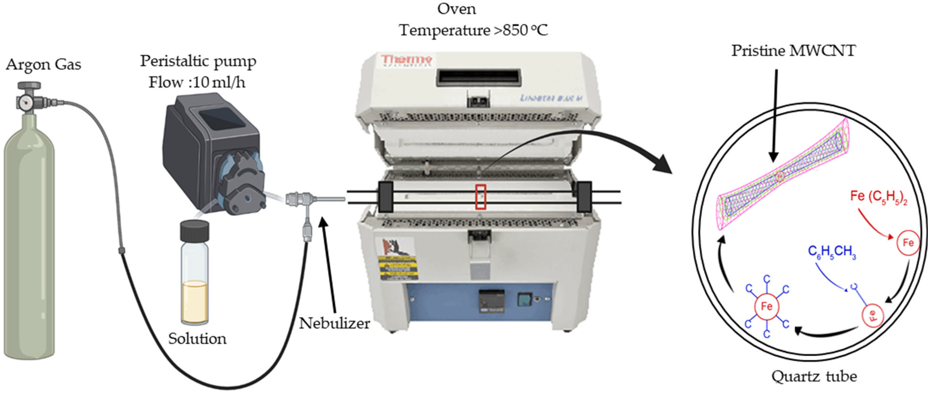
Figure 1. Synthesis scheme of MWCNT by the spray-pyrolysis method. Paz, J. (2025) https://BioRender.com/p86jijz.
Jcs 09 00167 g001
Figure 2. Schematic of PLA-MWCNT melt-blending process for layer printing and the fabrication of nano-reinforced composites. Paz, J. (2025) https://BioRender.com/p86jijz.
Jcs 09 00167 g002
Figure 3. Dispersion of MWCNT in epoxy resin by ultrasonic waves. Paz, J. (2025) https://BioRender.com/p86jijz.
Jcs 09 00167 g003
Figure 4. Scheme of the spray-coating process. Paz, J. (2025) https://BioRender.com/p86jijz.
Jcs 09 00167 g004
Figure 5. Raman spectrum of synthesis of pristine MWCNTs.
Jcs 09 00167 g005
Figure 6. Scanning electron microscopy of the pristine MWCNTs (synthesis 1) prepared via the spray-pyrolysis method.
Jcs 09 00167 g006
Figure 7. FTIR spectra of the MWCNT, PLA, PLA-MWCNT/CFRC, epoxy resin, PLA/CFRC-MWCNT, and PLA/MWCNT/CFRC.
Jcs 09 00167 g007
Figure 8. Thermograms of composites: (a) TGA and (b) DSC.
Jcs 09 00167 g008
Figure 9. Mechanical characterization: (a) stress versus strain plot of PLA/CFRC, PLA-MWCNT/CFRC, PLA/CFRC/MWCNT, and PLA/CFRC-MWCNT; (b) ultimate stress; and (c) elastic modulus.
Jcs 09 00167 g009
Figure 10. Scanning electron microscopy (SEM) images of the fracture in the nanocomposites evaluated in the tensile tests: (a) PLA/MWCNT/CFRC, (b) PLA-MWCNT/CFRC, (c) PLA/CFRC-MWCNT, and (d) PLA/CFRC-MWCNT.
Jcs 09 00167 g010
Figure 11. Percentage of cell viability (MTT) in peripheral blood mononuclear cells exposed for 24 h to the surface of the PLA/CFRC composite material and the multiscale composite materials of PLA/CFRC-MWCNT, PLA-MWCNT/CFRC, PLA/MWCNT/CFRC, CFRC, and PLA. All measurements were performed in triplicate (Σ ± DS). Σ = average; SD = standard deviation.
Jcs 09 00167 g011
Table 1. Properties of materials used to manufacture nano-reinforced materials.
MaterialDensity (g/cm3)Tensile Strength (MPa)Tensile
Modulus (GPa)
PLA filament1.24603.5
Carbon fabric1.763560230
Epoxy resin1.15653.63
Toluene0.86------------
Ferrocene1.49------------
Table 2. Methods of preparation and nomenclature.
SampleNomenclaturePreparation Method
1PLA/CFRCComposite base material
2PLA-MWCNT/CFRCFusion-blended composite of PLA and carbon nanotubes
3PLA/CFRC-MWCNTComposite with dispersion of carbon nanotubes in epoxy resin by ultrasonic waves
4PLA/MWCNT/CFRCComposite with MWCNT spray-coating on PLA and CFRC interlayers
Table 3. Thermal properties of the composites.
SpecimensThermal Degradation Temperature (Td), °C
Start (5% loss)Maximum (Onset)Weight Loss (wt%)Residue at 500 °C (wt%)Tg (°C)Tcc (°C)Tm (°C)
PLA335.7378.898.570.9455.897.3172.0
Epoxy resin342.7354.789.216.1584.4--------
PLA-MWCNT/CFRC324.4375.897.301.4951.781.3171.1
PLA/CFRC-MWCNT276.6338.690.394.3771.6--------
PLA/MWCNT/CFRC325.4343.189.935.0587.0--------
Disclaimer/Publisher’s Note: The statements, opinions and data contained in all publications are solely those of the individual author(s) and contributor(s) and not of MDPI and/or the editor(s). MDPI and/or the editor(s) disclaim responsibility for any injury to people or property resulting from any ideas, methods, instructions or products referred to in the content.