Article

Fiber-Reinforced Clay: An Exploratory Study on Automated Thread Insertion for Enhanced Structural Integrity in LDM

Department of Visual Arts, Faculty of Architecture, RWTH Aachen University, Schinkelstr. 1, 52062 Aachen, Germany
*
Author to whom correspondence should be addressed.
Ceramics 2023, 6(3), 1365-1383; https://doi.org/10.3390/ceramics6030084
Submission received: 6 June 2023 / Revised: 22 June 2023 / Accepted: 25 June 2023 / Published: 28 June 2023

Abstract

:
This exploratory study examines the potential of combining clay and natural fiber material in liquid deposition modeling (LDM) to enhance the structural integrity of the soft-bodied print during the additive manufacturing (AM) process. For this purpose, a custom extruder module and a support structure have been developed as novel additions to the delta 3D printer that allows for automated fiber thread insertion into the deposit clay body and stabilize the 3D print during drying. This study explores material compatibility and durability in the liquid state and the material strength of the sintered ceramic body after pyrolysis of the natural fibers. The findings demonstrate the feasibility of an automated process for thread insertion and tensioning control to stabilize and control the 3D print until drying and showcase the versatile design possibilities of this method. The study may serve as a baseline for future research on fiber-reinforced clay printing in the construction industry and related disciplines.

Graphical Abstract

1. Introduction

Liquid deposition modeling (LDM) technology, a pioneering method for 3D printing with ceramics, is making significant strides across multiple engineering domains [1,2]. Clay, a natural and malleable material, serves as the base medium in LDM. When subjected to a high-temperature process known as firing or sintering, the green clay body undergoes a physical-chemical transformation, turning into a ceramic body [3,4]. Ceramics offer properties of hardness, heat resistance, and durability [5], making them a valuable resource in various industries [6]. Their utility in the construction industry [7,8] is amplified when used in an LDM system due to their wide availability, cost-effectiveness, and sustainability [9,10]. However, LDM brings its own set of challenges. Among these are material discrepancies and inconsistencies in clay deposition [11,12] followed by material shrinkage [13,14,15], requiring careful consideration in the digital design process [16] and meticulous attention to the changing material properties and constant calibration of the printing parameters. Furthermore, these limitations may result in overhangs and deformations during printing, necessitating additional support and potentially restricting design freedom and form experimentation [17].
Research has been channeled towards using natural fibers, such as cellulose fibers, to strengthen soft materials such as clay until they are dried [18,19,20]. As a sustainable and flexible alternative to synthetic materials, cellulose fibers possess commendable tensile strength and renewable properties, making them suitable for diverse applications [21,22]. Current studies primarily focus on short fibers as reinforcement of the composite material [23,24]. However, fiber threads might present a promising potential for increased strength and improved structural integrity in the resulting 3D-printed soft-body clay [25,26]. Therefore, initial efforts were focused on incorporating composite reinforcements to mitigate material restrictions. However, the existing research has been limited to the manual insertion of the fiber thread without addressing the technical challenge of integrating spun threads into clay during printing [25].
This study aims to offer a novel approach to this challenge by developing a module for automated thread insertion and thread tensioning during the LDM process. By shifting from manual to automated clay reinforcement with fiber threads, the efficiency of soft-body extrusion is enhanced, and new design opportunities are made possible. Moreover, the use of natural fiber aligns with an increasing shift towards environmentally responsible manufacturing practices, further emphasizing waste reduction and supporting the circular economy.
This case study for automated fiber reinforcement in 3D-printed clay provides new possibilities for research and industrial applications, which could contribute towards a sustainable future of construction and design.

2. Materials and Methods

This study outlines the approach to prototyping the custom-build module, delving into the specifics of the LDM system and digital modeling, and exploring the unique properties of clay and fiber threads and their combined features during the printing process. The functionality and design of the custom-built module, facilitating automated fiber insertion, are discussed in detail, as are the strategies for examining the mechanical behavior and integrity of the printed samples, outlined by a series of exploratory experiments to assess the performance of these materials and the impact of the fiber insertion module (FIM). In addition, the results of parallel material analyses examining the composite material are presented and discussed, addressing potential localized structural weaknesses resulting from the disintegration of the fiber threads during sintering.

2.1. Liquid Deposition Modelling (LDM) System

The Delta WASP 40100 clay printer, utilized for this research, has a cylindrical print volume of 400 mm in diameter and 1000 mm in height. It employs the LDM system using a liquid material supplied from an external cartridge driven by compressed air. In the deposition process, no heat is applied as the material is already in a liquid state. It is important to note that the printer lacks a default sensor system, which is already standard in various robotic systems. This absence manifests in three significant operational challenges. (1) Without collision detection sensors, the printer is unable to autonomously avoid inadvertent collisions with obstructions, potentially leading to damage to the printer, print, or both. In addition, (2) the content level of the cartridge is not automatically monitored. This may lead to unexpected interruptions of operations due to material exhaustion, necessitating continuous operator oversight to ensure sustained supply. Finally, (3) the printer does not have a means of monitoring the consistency of the printing material in real time. Variations in material consistency can directly impact print quality. However, such inconsistencies might not be detected, leading to potential quality discrepancies or print failures.

2.2. Prototyping

The prototyping methodology comprises two distinctive aspects: (1) the development of custom-built modules (see Section 2.2.1) and (2) the creation of exemplary structures (see Section 2.2.1). The liquid state of the soft clay during extrusion through the LDM printer facilitates the distinct development of additional modules.

2.2.1. Developing Custom-Built Modules

The development of the custom-built module primarily hinged on two elements: (1) conceptualizing and creating designs using CAD and 3D modeling software (McNeel’s Rhinoceros3d/Grasshopper, see Section 2.2.2) and (2) obtaining mechanical components while generating custom parts using a stereo-lithography (SLA) printer. Given that the module was custom-designed, specific components were not readily available for purchase, necessitating the production of custom parts. For this purpose, an SLA printer was selected because its accuracy level and print volume are suitable for producing exact machine parts to augment the Delta WASP 40100 clay printer. The decision to use an SLA printer was also informed by its quick production time and the durability of its photopolymer resin, compared to a fused deposition modeling (FDM) printer [27,28]. The transparent photopolymer resin used to produce the parts facilitated the monitoring of the clay and thread insertion during the printing process.

2.2.2. Digital Modelling

Throughout the course of this study, the Grasshopper Add-On for McNeel’s Rhinoceros3d was essential to scripting and parametric design. Grasshopper was used for the slicing process and G-code generation. It allows an in-depth examination of detailed parameters, which is typically not possible with standalone slicer software. Slicing refers to the transformation of a 3D model into a series of layers or “slices”, effectively converting the design into a format that the 3D printer can interpret [29,30]. On the other hand, G-code is a language that communicates with automated machine tools such as the LDM printer, telling it when, where, and how to move during the printing process [29,30]. Therefore, using Grasshopper for slicing and G-code generation meant gaining greater control over a broader range of parameters. This includes, but is not limited to, manipulating extrusion speed, adjusting the extrusion rate, controlling the timing, location, and quantity of material extrusion or retraction, and even programming pauses or stops in the printing process, which is not possible in conventional slicing programs.

2.3. Clay

This study utilized a stoneware clay body comprising 25% chamotte with grain sizes ranging from 0 to 0.5 mm. The clay was subjected to a drying and rehydration process in pursuit of the optimal consistency conducive to 3D printing, as a marginally softer clay mixture with a more significant water content yielded superior results. However, this method led to an increase in the wet-to-dry shrinkage value of the clay. Specifically, the shrinkage of the stoneware body increased from 6.8% [31] to 14.2% (see Table 1). This significant increment in shrinkage raises critical considerations for the process, specifically for dimensional changes during drying, as further discussed in Section 2.3.1.

2.3.1. Clay Shrinkage

Understanding the shrinkage properties of the soft-body clay is crucial for a comprehensive characterization of the material, given its inherent contribution to the complex behavior of clay in LDM applications. The “Shrinkage Limit” [13,14] occurred at approximately 21 h and 43 min with a corresponding shrinkage of 85.79%. It marked a significant transition between two trendlines and is the threshold beyond which no further shrinkage was observed.
For the clay shrinkage investigation, a clay sample was extruded using a delta 3D printer, measuring 9.5 cm in length, 4.6 cm in height, and 1 cm in width. The fabrication occurred indoors under controlled environmental conditions, with a temperature of approximately 19 °C. It is important to note that the specific indoor temperature and humidity levels were not documented during the investigation. However, for contextual understanding, the average outdoor temperature was recorded at 12.1 °C with a minimum and maximum of 0 °C and 14 °C, respectively, while the humidity level averaged 67%, oscillating between 50% and 87% [32].
Over an observational period of 51 h and 28 min, data were collected primarily through manual photography at varying intervals, facilitating the analysis of the dimensional changes of the sample over time. The results of the shrinkage investigation are presented in Figure 1. It aims to offer an understanding of the shrinkage properties of the clay by outlining two distinct phases—the “Shrinkage Phase” and the “Constant Phase”, with a critical transition point identified as the “Shrinkage Limit”.

2.4. Fiber Thread

The material used in this study was a hemp twine designated “Nm 28/2” (see Figure 2), which is spun from water-retted and subsequently bleached hemp fibers [33]. The term “Nm” refers to the metric count of the yarn, indicating the length in meters per gram of yarn [22]. In this case, “Nm 28/2” denotes that 28 m of this yarn weighs 2 g.
The thread exhibits a significant level of tensile strength with 20.5 N (see Table 2). Its rigid nature, combined with its composition—twisted from two individual strands—enhances its robustness and thickness, attributes that are particularly advantageous in this study. Moreover, microfibers projecting from the main thread (see Figure 2(a1)) improve adhesion with the clay, thereby increasing the resilience and durability of the resulting composite.

2.4.1. Thread Evaluation

The evaluation of the hemp thread Nm 28/2 bonding characteristics within a clay composite was critical in this study. Therefore, other threads were also considered. Six threads from hemp and linen varieties were initially examined based on attributes, including visual properties, composition, yarn count, and the spinning process utilized. Furthermore, all of these threads possessed a significant degree of rigidity. The evaluation process involved three distinct testing scenarios (see Table 2): (1) Clay–fiber bond in extrusion; (2) thread pulling in soft clay; and (3) thread pulling in dry clay. (1) sought to simulate the 3D printing process, initially evaluating the bonding efficacy between the thread and the clay. The hemp thread Nm 28/2 demonstrated an effective bond with the clay, with the comparably thicker yarns performing exceptionally well. (2) aimed to quantify the degree of adhesion between the clay and the thread during the plastic, flexible stage immediately following extrusion. (3) was designed to evaluate the bond strength after a drying period of three days, closely approximating the final condition of a 3D-printed clay object. In this test, the bond strength between the thread and clay exceeded initial expectations, as the threads remained embedded within the dry clay and broke before they could be extracted. While other threads were also evaluated, their performance did not match that of the hemp thread Nm 28/2. Accordingly, these preliminary findings pointed towards the selection of hemp thread Nm 28/2 for further testing and studies within this research due to its successful bonding with both the liquid and dried clay, signifying its optimal suitability for this research context.

3. Clay and Fiber Thread Composite

The intricate relationship between clay and thread is central to this research, making the choice of a natural fiber crucial. The selected fiber, hemp thread Nm 28/2, inherently facilitates natural hydrogen bonding and wetting dynamics, which come into play when interacting with hydrophilic materials [21], such as liquid clay, fostering improved bonding and compatibility compared to synthetic fibers [34]. This mutual interaction is crucial in the 3D printing process, emphasizing the importance of material selection in this study. Furthermore, the composite undergoes a sintering process, exposing it to high temperatures where the natural thread pyrolyzes, leaving no harmful residues. Additionally, the fiber diameter was an important parameter evaluated in this investigation. Due to the restrictions imposed by the 6mm diameter of the nozzle, preference was given to a relatively thin thread. This decision, however, was not solely driven by the mechanical constraints of the extrusion nozzle but also aimed at maintaining an optimal ratio between the clay and fiber in the composite material. Utilizing a thicker fiber could potentially disrupt this ratio and lead to larger voids following the sintering process, thereby reducing the structural integrity of the final ceramic product. In addition, it was essential for the chosen thread to exhibit high tensile strength and possess a substantial surface area, as both factors contribute to a strong bond with the liquid clay, as discussed in Section 2.4 and Section 2.4.1. The combination of clay and fiber threads also introduces an element of material efficiency to the process. In the event of a printing error, the clay and fiber can be easily separated and re-used, highlighting the recyclable nature of these materials.

Material Strength after Sintering

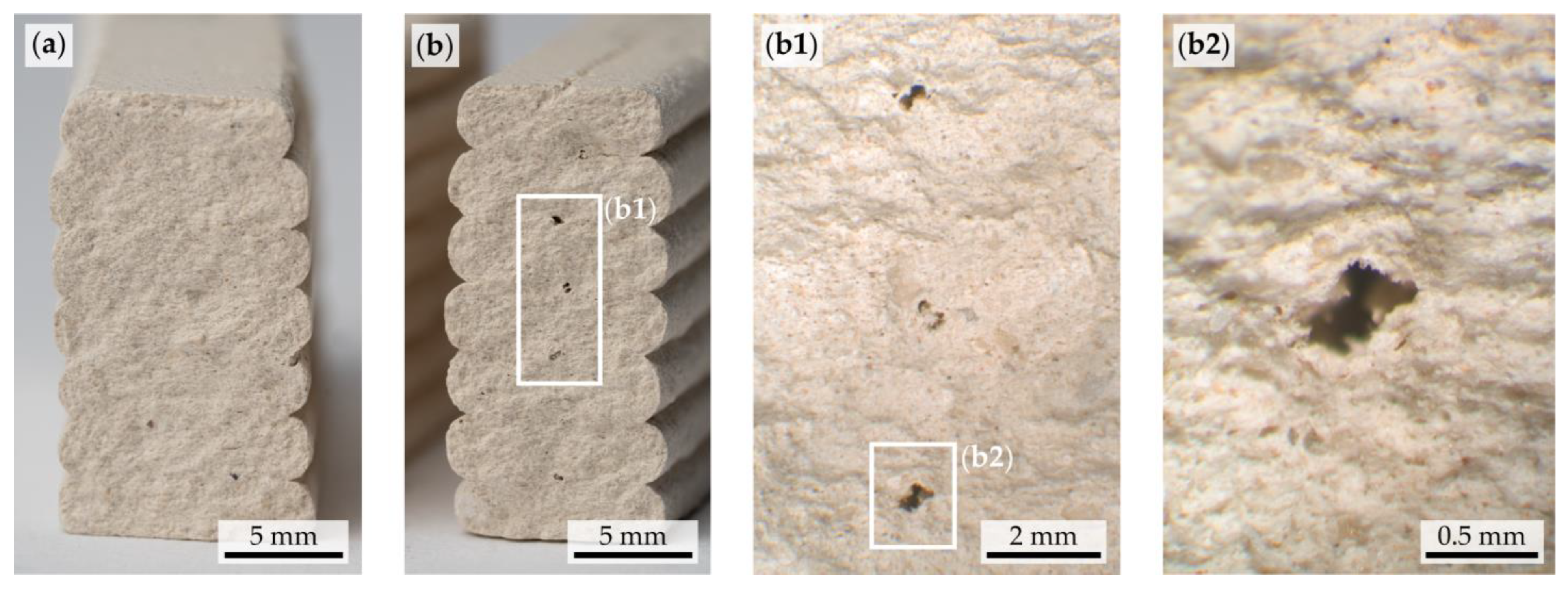
The three-point bending tests play a critical role in assessing the structural integrity of the clay composite after the sintering process. Once embedded in the clay composite, the natural fiber thread pyrolysis during sintering, leaving voids in the final sintered product. This test aimed to explore two specific situations: (OB) a control situation involving no thread, and (HB) a situation involving the integration of the selected hemp thread Nm 28/2. Therefore, samples were fabricated for each situation, utilizing the Delta WASP 40100 clay printer, ensuring consistency and repeatability in results. The samples were sintered at 1080 °C and then sanded, ensuring the plane-parallel top and bottom sides to facilitate accurate three-point bending tests. The results highlight the resilience and stability of the ceramic structure, even after the natural fiber thread has disintegrated post-sintering. Furthermore, the resulting voids were within the size range of the largest chamotte particles (see Figure 3) and did not significantly harm the structural integrity of the clay (see Figure 4). Importantly, these voids had no significant weakening effect on the structural integrity compared to the control samples without fiber.

4. Custom-Build Module

The development of a custom module aimed at the automatic integration of fibers into a clay strand during the 3D printing process. Two significant developments underpin this module: the fiber insertion module (FIM) and the tensioning structure on the building plate. In the process of embedding fibers into the clay body, it is crucial to control precisely when and where the fiber is introduced, with the goal being to position the fiber as centrally as possible within the clay and each extruded layer. Furthermore, the ability to manipulate the placement of the fiber has the potential to influence the physical properties of the resulting composite significantly.

4.1. Fiber Insertion Module (FIM)

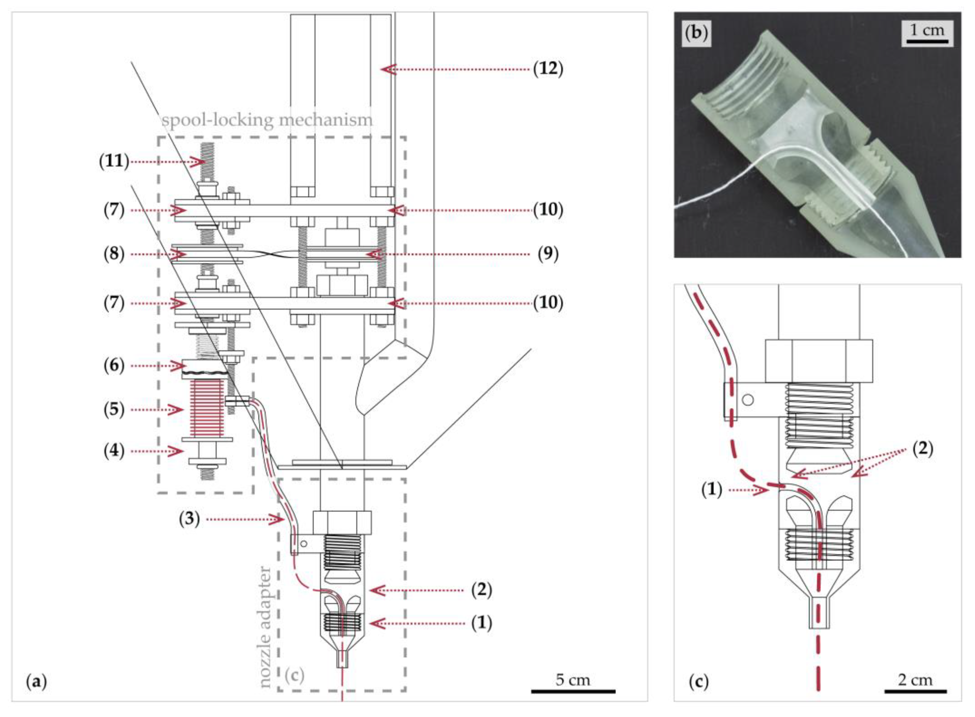
The study involved designing and creating the fiber insertion module (FIM) for the Delta WASP 40100 clay printer to facilitate the automated integration of thread into the clay during printing (see Figure 5 and Figure 6). The aim was to use the extrusion process of the clay and extrude the reinforcement material simultaneously.
In addition, sequential extrusion, in particular, is of interest when thread extrusion is needed independently, without the concurrent deposition of clay. One such scenario could be creating a reinforcing structure on which soft clay could be extruded. The capability of FIM to extrude only the thread is essential in such situations. The tensioning structure attached to the building plate, described in Section 4.2, facilitates this function. This additional structure allows the winding of the thread, enabling its extrusion while the printer follows a predetermined path without extruding any clay. The premise behind the selective extrusion of the thread is to establish a preformed, tensioned structure that supports the subsequent clay extrusion. This preformed structure can aid in overcoming limitations imposed by the natural properties of the soft clay, such as its tendency to slump or deform under its weight when building overhanging or complex shapes. Therefore, the capability of the FIM to extrude thread independently, combined with the tensioning structure on the building plate, offers expanded possibilities for more complex and structurally stable 3D-printed clay objects. Furthermore, the clay body receives additional support during the extrusion and the shrinkage phase (refer to Section 2.3.1 for details), a notable advantage of this methodology.
The FIM consists of two essential parts: (1) an adapter for the nozzle and (2) a spool locking mechanism.
The adapter features a lateral entry point, which leads the thread into a channel of 1.5 mm in diameter. The channel, taking a right-angled orientation from the side towards the nozzle end, is supported by two connecting junctions on the inner wall of the cylindrical adapter. This design allows the clay to be split into two parts during the extrusion process, with the thread positioned in the center (see Figure 5(a1,b) and Figure 6(b3)). As the liquid clay progresses towards the nozzle, it merges with the thread through the narrowing interior of the cylindrical adapter and the nozzle, ensuring enough adhesion to bond and be extruded simultaneously. In this stage, a freely swinging spool with minimal friction is paramount. In addition, it plays a critical role in ensuring the proper extrusion of the thread alongside the clay, as the sole source of traction originates from the malleable clay itself. This prototypical design was employed in all subsequent testing and explorative experiments. Additional parts are conceived of as modules primarily held together by screwing mechanisms, thus allowing for easy assembly, disassembly, and exchange of parts when necessary, enhancing operational efficiency and adaptability. The need for an additional extension becomes evident when trying to accommodate the length of the tensioning structure on the building plate, as described in Section 4.2, along with the printer system. In such scenarios, an increased length of the nozzle is required to appropriately navigate the added structure and maintain the intended printing path.
The spool-locking mechanism was developed to control the spool rotation during specific periods (see Figure 5a and Figure 6(b1,b2)). The mechanism utilizes the rotary motion of the stepper motor of the printer, which is connected to the extruder, by converting its rotational direction into a locking or releasing action. That connection is exposed by the default system of the printer, allowing for free access. The system is programmed in such a way that it extrudes material when rotating clockwise and retracts material when rotating anticlockwise. Therefore, the system can be adjusted so that the spool rotates freely whenever the printer extrudes material while slightly locking the spool to prevent free movement during material retraction. The mechanical transmission is achieved through pulleys and a crossed belt. One of the pulleys is directly connected to the extruder, while the other is connected to a threaded rod via a one-way clutch. The one-way clutch allows rotational movement in one direction while automatically locking in the opposite direction. Thus, the one-way clutch rotates during extrusion to prevent the threaded rod from rotating. However, the one-way clutch does not rotate during retraction, while the threaded rod does. The use of a crossed belt reverses the direction of rotation between the first and second pulleys, which is particularly useful given the choice of a trapezoidal threaded rod secured with bearings to prevent movement on the vertical axis. The threaded rod is crucial for the vertical movement of the nut, which moves in response to the rod’s rotational motion. More specifically, when the rod rotates in a clockwise direction, the nut moves upwards, and when it rotates in the opposite direction, the nut moves downwards. This movement is used to lock the spool, and both the nut and the spool are connected to a serrated locking plate designed to relieve the spool of excess tension in the thread. In addition, a spring is placed between the nut and the serrated locking plate to prevent system breakage and ensure adequate tolerance for further relief of the spool.

4.2. Tensioning Structure on Building Plate

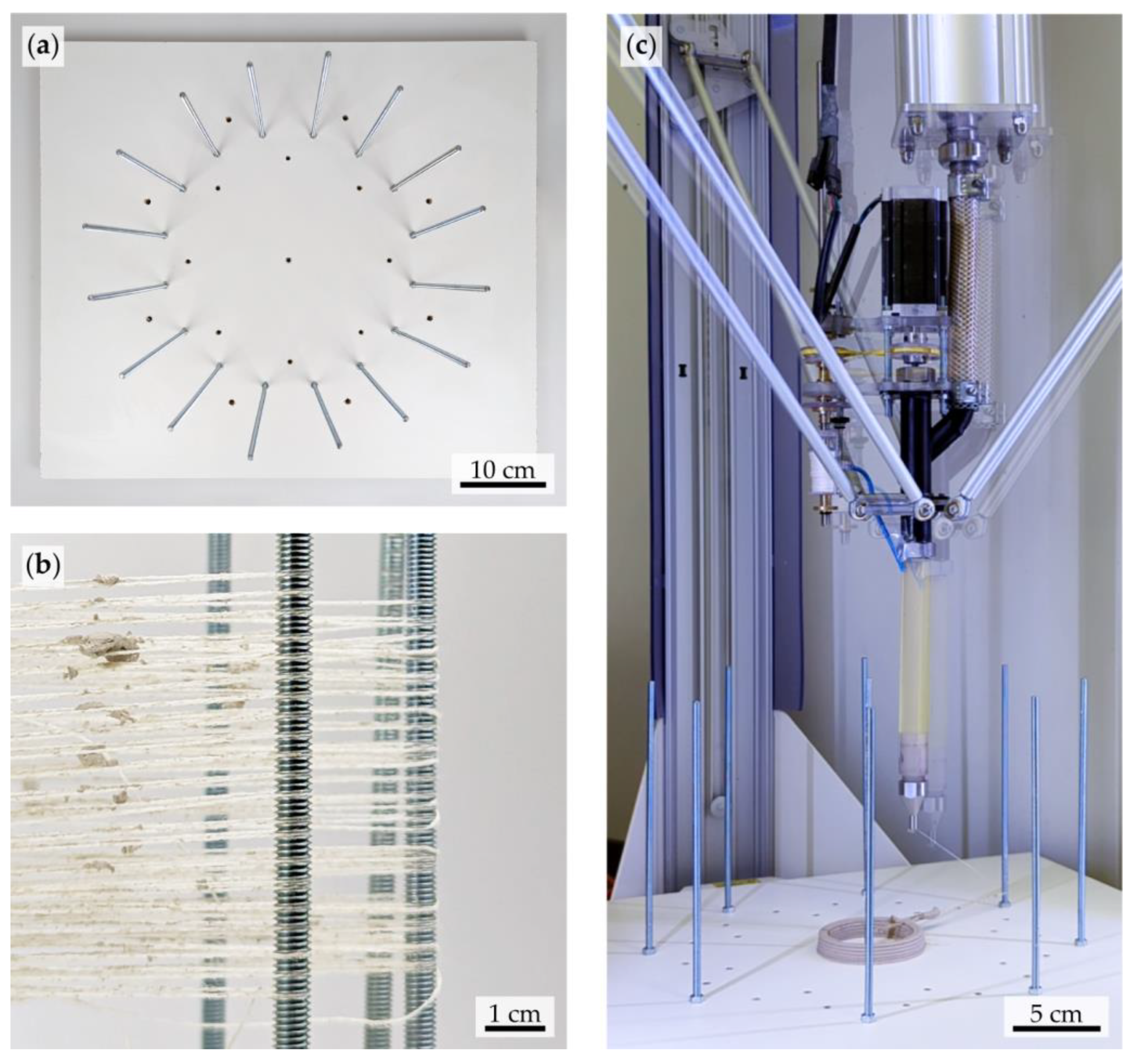
Maintaining consistent thread tension is vital in the fabrication process, necessitating the integration of a tensioning structure on the building plate as pin-points for wound fiber thread alongside the FIM (see Figure 7). This study utilizes threaded rods as key elements of the tensioning structure; their design ensures the secure fastening of thread loops. These rods can be customized to suit a range of design possibilities, granting a high level of adaptability due to assembly and disassembly (cf. [35]). Furthermore, the threaded surface of these rods allows for secure winding of the thread, minimizing slippage and maintaining consistent tension throughout the process (see Figure 7b). The winding technique is reminiscent of the traditional string art method, which utilizes evenly spaced nails or pegs to maintain a consistent and organized winding pattern [36,37]. Adopting such a method for the tensioning structure further guarantees the effective management of thread tension throughout the fabrication process.
In this study, the design for the tensioning structure on the building plate was arranged to maximize the use of the delta printer’s 40 cm diameter limit, as previously outlined in Section 2.1. A radial array design (see Figure 7a) was implemented, with each rod evenly spaced 4.2 cm apart, ensuring sufficient space for the FIM to navigate around the threaded rods without any interference. In addition, the presence of at least two counterposed support structures is crucial. This arrangement facilitates efficient tensioning and results in two parallel threads side-by-side. This dual thread formation enhances the support provided to the extruded clay due to the doubled surface area. The specific layout of these support structures can be adjusted according to individual project needs, reflecting the adaptability of this methodology.

5. Exploratory Experiments with Custom-Build Module

Integrating fiber threads with clay in 3D printing through the FIM strengthens and stabilizes the printing process. Each horizontal layer of the extruded clay is followed by an additional layer of a pre-wound structure when it is necessary. This procedure of alternate layering persists until the need for extra support is mitigated.
The primary goal of this study is not to create a specific ceramic product but to explore and showcase the extended design capabilities facilitated by the novel module. This part of the study aims at the production of extruded structures exhibiting significant overhangs. The principal focus is on the feasibility of a horizontal overhang (see Section 5.1) and creating an off-centered freeform structure with a considerable overhang (see Section 5.2). Both approaches depend on pre-wound threads functioning as a support system built upon the tensioning structure on the building plate, as outlined in Section 4.2. Further examinations were then carried out, expanding upon the potential of the technology (refer to Section 5.3 and Section 5.4).

5.1. Horizontal Overhanging Bars

The feasibility of a horizontal overhang is demonstrated in Figure 8, which showcases eight printed lengths ranging from 5 to 12 cm on a wound fiber thread. It was observed that shorter distances resulted in more precise outcomes than longer bars. However, as this distance increases, so does the likelihood of the nozzle head dragging along the freshly extruded clay strand. The alternating direction of the printing path amplifies this issue as some strands mimic this oscillating pattern, primarily due to insufficient adhesion between the liquid clay and the minimal surface contact provided by the thread beneath. This phenomenon highlights the critical role of achieving optimal adhesion to maintain the extruded clay’s intended placement. Figure 8 exhibits a range of horizontal overhang structures, featuring three distinct scenarios. Initially, successful horizontal bars are demonstrated, as outlined in Figure 8(c1), evidencing the potential of this method. Subsequently, an instance is identified where the extruded clay does not achieve the required adhesion to the thread. This adhesion failure leads to a displacement of the first layer, as highlighted in Figure 8(c2), pointing to an area for potential improvement in future iterations of this technique. Finally, Figure 8e shows a situation where misalignment of the building plate and overly soft clay results in the strand falling between two parallel wound threads. This scenario underscores the crucial role of precise alignment and appropriate clay consistency for the successful execution of the horizontal overhang technique.

5.2. Freeform Body

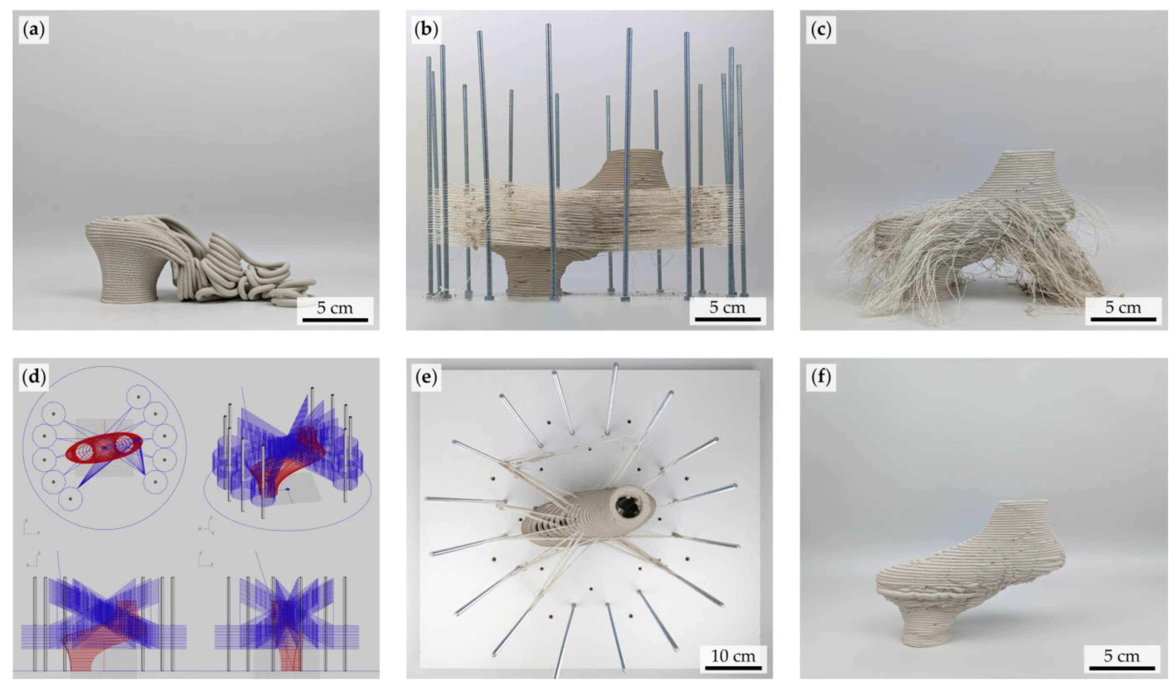
The printed off-centered freeform geometry features a substantial overhang and is intentionally designed to be unstable without external support (see Figure 9). This design demonstrates the flexibility of the threaded rod support system, as mentioned in Section 4.2. Figure 9e presents the configuration of the rod system employed in this study and the freeform body supported by the wound fiber threads. Instead of incorporating every rod in the radial array, as depicted in Figure 7a, a more strategic approach was used. The rods were selectively positioned based on their potential contribution to the support and stability of the freeform body. The aim was to optimize coverage and reinforcement across the body’s complex structure, ensuring that critical areas received the required support. The model comprises a self-sustaining portion and another that necessitates thread reinforcement for stability. The printing process alternates between thread winding and horizontal material extrusion in an iterative cycle, confirming the capability of printing such a freeform structure. When comparing the two print processes—one with thread support and one without—it was observed that the print time with thread support (see Figure 9b) was approximately ten times greater than the process without additional support (see Figure 9a). This increased duration is primarily due to the slower feed rate (or speed of the printed path) implemented as a precautionary measure to minimize potential errors during the printing process.
The wound thread supports the clay body during drying. However, the selected geometry introduces unique challenges associated with material shrinkage. To mitigate this, connections to the tensioning structure were severed about 16 h after the conclusion of the print. This precautionary measure ensured that the printed body did not suffer from cracks or breakages caused by shrinkage. Further elaboration on a contrasting scenario will be presented in the following discussion, Section 6.

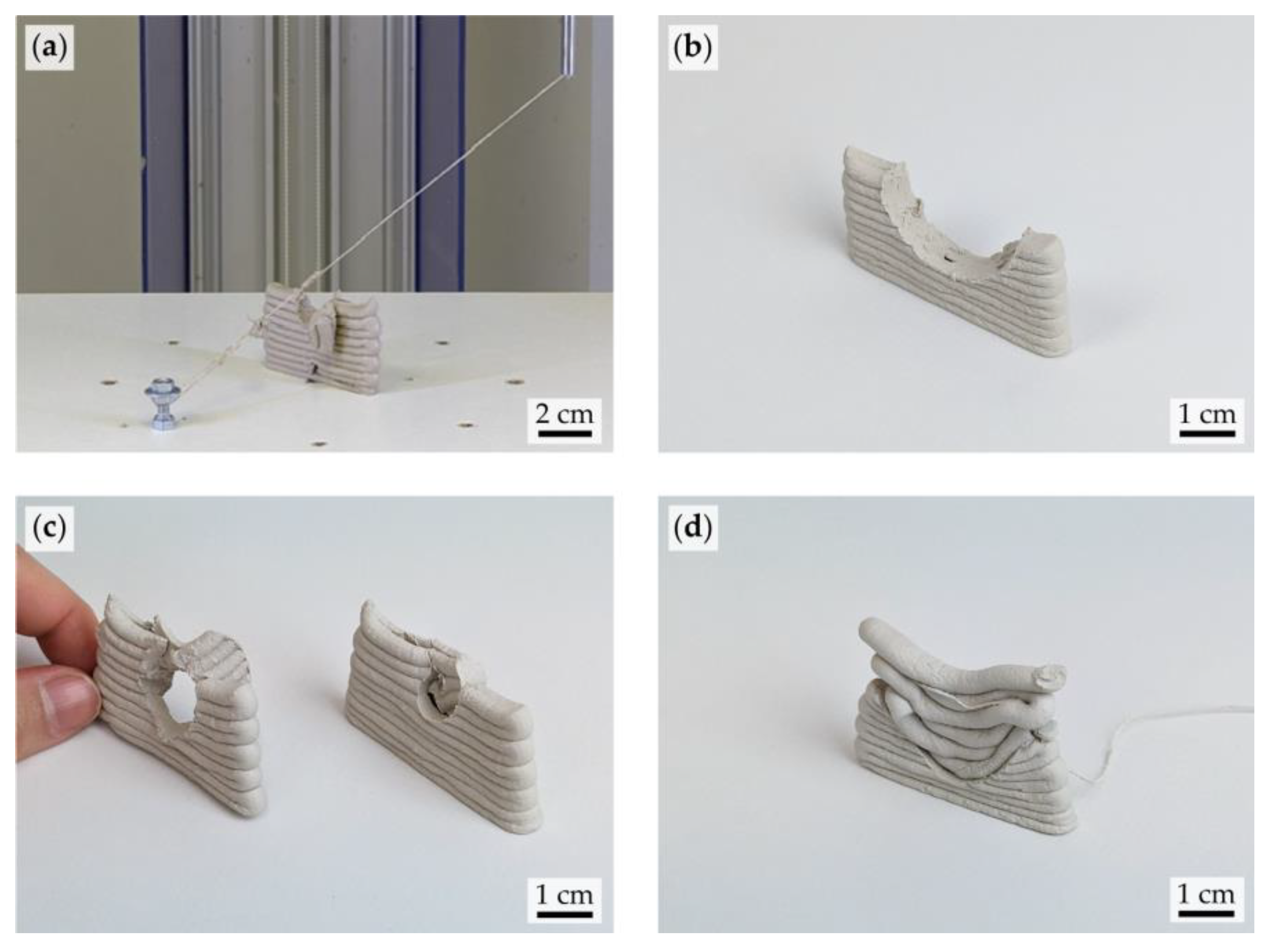
5.3. Subsequent Subtraction

This section introduces a distinctive method involving thread as an instrument to shape and slice through a clay body. This possibility arises due to the soft and malleable character of the clay during the extrusion process. Material subtraction from an already printed soft clay body allows for design flexibility, including part separation or decorative cutouts. This technique was tested on various shapes to understand its potential, as seen in Figure 10. The technique starts with a thread-free clay body on the building plate, with a threaded rod as an anchor for the thread loop. The desired cutout design is virtually projected onto the clay body’s side opposite the rod, establishing a geometrical correlation between the rod and the projection. This method allows the thread to cut through the clay, creating the desired designs. Maintaining thread tension during the cutting process is critical, as excess resistance from the clay could slacken the thread, preventing it from slicing the material effectively. This issue was mitigated by gradually shifting the projected path from its center point to the threaded rod, which helped restore thread tension. Further, as mentioned in Section 4.1, the spool-locking mechanism enhanced the tension of the thread, enabling more efficient cutting through the clay.

5.4. Vertical Printing in Clay Extrusion

The FIM enables vertical printing by providing additional support via a central thread in the clay strand, in contrast to horizontal printing, where the weaker clay-fiber bond results from the thread positioning at the top of each layer. Here, the thread serves as both a guide and a support system for the clay strand. An example of this method is the construction of vertically printed fiber-reinforced clay strands forming a wall structure (see Figure 11a,b). The process commences with an extruded anchor point on the building plate for adhesion, followed by upward extrusion. The extrusion slightly inclines towards the support structure, forms a 90-degree arc, and proceeds downwards. Additional extrusion secures the strand back to the building plate. However, this method demands precise printing settings. Maintaining a consistent, uniform extrusion rate is essential to avoid issues such as under- or over-extrusion, which occur when too little or too much material is extruded, leading to poor adhesion or an overly thick strand. Addressing vertical printing challenges necessitates carefully monitoring and adjusting printing settings, including extrusion rate and pressure.

6. Discussion

The novel addition of the automated Fiber Insertion Module (FIM) to the Delta WASP 40100 clay printer has brought valuable insights into the ceramics and 3D printing technology fields. This study entailed a comprehensive understanding of the distinct characteristics of the materials, yielding insights particularly relevant to the functionality and potential of the FIM. One of the key achievements of this study was the creation of large overhangs with liquid materials using 3D printing, which was traditionally deemed impossible. This achievement provides a substantial step forward in the way we can manipulate materials during deposition. The reinforcement of clay structures using thread winding facilitated the construction of wide-ranging overhangs in diverse appearances and shapes. An extended use case has been explored to use the thread to subtract material from a pre-printed clay body. This method presented a unique opportunity for enhanced material manipulation, allowing the initial subtraction of material from the clay body and adding a new layer onto the recently exposed surface.
The primary idea of the FIM aimed to position the thread within the core of the clay strand to ensure optimal bonding. However, it was found that this objective could be effectively achieved only when the extrusion was carried out vertically rather than horizontally. This is attributed to the direction of printing; as the clay is extruded horizontally, the already extruded clay uses a pulling force on the thread, causing a shift in its position towards the edge of the nozzle. As a result, the thread is primarily located on top of the deposited clay layer rather than integrated within it (see Figure 3b,b1). This displacement disrupts the bond between the clay and thread, leading to a less than anticipated adhesion quality. However, adding a subsequent layer encapsulates the thread. This layered integration manages to secure the thread within the structure, although not within the clay layer as initially intended. Further research should be conducted to explore additional design possibilities.
Incorporating a structure on the building plate for tensioning and extruding the thread introduces intriguing prospects for further investigation. Current wound patterns are relatively straightforward, not requiring complex algorithms. However, an avenue for exploration is the study of algorithms specifically tailored to the requirements of the printed clay body, considering the adaptability required in each scenario and at each layer. This signifies a shift towards creating individualized reinforcement patterns, potentially enhancing the structural integrity of the clay bodies. In addition, algorithmically tailored wound patterns could adapt to the unique needs of each layer and scenario, paving the way for more refined, robust, and efficient clay structures. This concept brings a new dimension to 3D printing, where customization is not merely about external design parameters but extends to the internal structural frame of the printed object.
While this research project has significantly progressed toward enhanced LDM, challenges persist, highlighting the need for ongoing research and development. As each layer of the winding process progresses, there is an escalating risk of the print head intersecting the wound structure. This could potentially lead to damage to the FIM, displacement of the building plate, or overstress of the wound thread, emphasizing the need for a robust system design and careful execution. While the photopolymer resin served as an accessible material for prototyping the extensions in this study, difficulties were encountered during the process of extended extrusion of the liquid material. Therefore, it is important to consider more wear-resistant materials, such as metal, which can withstand higher pressures, ensuring a more reliable printing operation. The absence of sensor technology in the LDM printer and the FIM is evident here. Incorporating such technology could offer real-time feedback throughout the printing process, potentially preventing accidents such as collisions or malfunctions that may damage the FIM, disturb the integrity of the clay body, or cause the thread to break. These sensors could supervise parameters such as distance to potential obstacles, thread tension, consistency of the extruded clay, the remaining quantity of clay in the cartridge, and the amount of thread left on the spool. This level of automated oversight would reduce manual intervention, enhancing overall process efficiency and precision.
Another substantial challenge is the present shrinkage of the clay. As the winding of the thread suggests additional support and reinforcement of the clay body, it also has to deal with the tension of the threads in one direction and the shrinkage of the clay in the other. Crucial breakages and cracking of the clay body were observed after drying, specifically when the thread was not severed, as depicted in Figure 12. Therefore, exact timing is required to prevent structural issues in future experiments. Particularly when reinforcing clay bodies with thread fiber, it is necessary to sever the thread before exceeding the Shrinkage limit. Based on the current data, cutting the thread is recommended when the shrinkage reaches 90% to 95% of the original size of the clay body. However, these figures serve merely as guidelines, as the specific conditions of each clay body may vary in size and weight. Furthermore, external factors such as humidity and sunlight exposure can also significantly influence the shrinkage behavior, leading to slight variations in the data and, consequently, the trendlines.
Adding to this complexity, the additional paths required for winding the thread significantly increase the print time. This is further compounded by the substantial computation time required by the software used in the design and execution of the printing process, thereby adding a time complexity layer to the already extended print time. However, it is important to note that despite this increased time commitment, the automated 3D printing process is still considerably more efficient and accurate than traditional manual methods.
The spool locking mechanism needs further research to determine the optimal locking moment to avoid tearing the thread. The most significant tearing occurred when the serrated locking system was pressed too tightly, limiting the rotation of the spool when excessive tension occurred, leading to the breaking of the thread. Further research needs to be conducted on the calibration method for the spool’s position.
While the requirement for continuous monitoring represents a challenge, it also underscores the need for flexibility and adaptability—qualities incorporated into the printer modules developed within this study. Despite being tailored to the existing Delta WASP 40100 clay printer, the newly designed module is not confined to this singular model. The adaptability of the FIM is of particular interest. The nozzle adapter can readily accommodate hardware nozzle configurations by altering the thread type. This adaptation could be achieved by implementing an adapter or making minor adjustments to the existing FIM.
Conversely, adjusting the spool locking mechanism involves more complex challenges. As described in Section 4.2, the mechanism uses the rotary motion of the stepper motor, effectively harnessing its mechanical movement for its operation. A similar mechanism to capture the rotary movement of material extrusion or retraction would be essential to adopt this feature to other printer models. In the presence of such a feature, only minor modifications would be necessary to install the spool locking mechanism. An alternative approach could be conceived without this feature by constructing an independent system. This system could match the rotation ratio of the printer with an auxiliary motor. This level of versatility underscores that the developments of this research carry potential applications beyond the initial printer model, thus demonstrating the wide-reaching implications of these findings for the broader field of 3D printing and robotics.

7. Conclusions

The results from this study have offered insightful observations and paved the way for promising developments in liquid deposition modeling (LDM). The findings of this research demonstrate several key points:
  • The fiber insertion module (FIM) has been proven capable of automating threads’ integration into the clay during the 3D printing process.
  • Incorporating a novel principle for support structures, based on thread winding attached to the tensioning structure on the building plate, creates complex geometries.
  • With this approach, it is now possible to achieve designs featuring horizontal overhangs and freeform structures, which were beyond the reach of traditional LDM methodologies.
  • Reinforcing the clay body with fibers significantly strengthens the printed structure during the printing and drying stages.
  • Using natural fibers and clay underscores the shift towards more environmentally friendly practices within composite materials, particularly as separating and re-using these materials is straightforward and the incineration of natural fiber threads leaves a minimal environmental impact.
  • No significant consequences for the structural integrity of the printed clay body were observed due to the thread insertion process.
The modifications pave the way for future studies and push the boundaries of what is currently deemed possible within liquid 3D-printed ceramics. It encourages the continuation of this journey and urges future researchers to venture further into this realm of discovery. In conclusion, the proposed method holds promise for introducing new perspectives within architecture, design, and additive manufacturing.

Supplementary Materials

The following supporting information can be downloaded at: https://www.mdpi.com/article/10.3390/ceramics6030084/s1, Video S1: Horizontal overhangings printed with additional support; Video S2: Freeform structure printed with additional support; Video S3: Freeform structure printed without additional support.

Author Contributions

Conceptualization, H.-Q.Y. and C.K.; methodology, H.-Q.Y. and C.K.; software, H.-Q.Y.; formal analysis, H.-Q.Y.; investigation, H.-Q.Y.; resources, T.H.S.; data curation, H.-Q.Y.; writing—original draft preparation, H.-Q.Y.; writing—review and editing, C.K.; visualization, H.-Q.Y.; supervision, C.K. and T.H.S.; project administration, H.-Q.Y. and C.K. All authors have read and agreed to the published version of the manuscript.

Funding

This research received no external funding.

Institutional Review Board Statement

Not applicable.

Informed Consent Statement

Not applicable.

Data Availability Statement

The data presented in this study are available in this article and the Supplementary Materials.

Acknowledgments

The authors thank Laurens Bekemans of the Junior Professorship of Construction and Design at the RWTH Aachen University for their insightful feedback and continual support throughout this research.

Conflicts of Interest

The authors declare no conflict of interest.

References

  1. Klug, C.; Herzog, S.; Kaletsch, A.; Broeckmann, C.; Schmitz, T.H. Forming of Additively Manufactured Ceramics by Magnetic Fields. Ceramics 2022, 5, 947–960. [Google Scholar] [CrossRef]
  2. Jang, S.; Park, S.; Bae, C.-J. Development of ceramic additive manufacturing: Process and materials technology. Biomed. Eng. Lett. 2020, 10, 493–503. [Google Scholar] [CrossRef] [PubMed]
  3. Lee, V.-G.; Yeh, T.-H. Sintering effects on the development of mechanical properties of fired clay ceramics. Mater. Sci. Eng. A 2008, 485, 5–13. [Google Scholar] [CrossRef]
  4. German, R.M. Sintering Theory and Practice, 1st ed.; Wiley: New York, NY, USA; Chichester, UK, 1996; ISBN 978-0-471-05786-4. [Google Scholar]
  5. Basu, B.; Balani, K. Advanced Structural Ceramics; Wiley: Hoboken, NJ, USA, 2011; ISBN 9780470497111. [Google Scholar]
  6. Bechthold, M.; Kane, A.; King, J. Ceramic Material System: In Architecture and Interior Design; Birkhäuser Verlag GmbH: Basel, Switzerland, 2015; ISBN 978-3-03821-843-2. [Google Scholar]
  7. Wolf, A.; Rosendahl, P.L.; Knaack, U. Additive manufacturing of clay and ceramic building components. Autom. Constr. 2022, 133, 103956. [Google Scholar] [CrossRef]
  8. Kontovourkis, O.; Tryfonos, G. Robotic 3D clay printing of prefabricated non-conventional wall components based on a parametric-integrated design. Autom. Constr. 2020, 110, 103005. [Google Scholar] [CrossRef]
  9. Farahbakhsh, M.; Rybkowski, Z.K.; Zakira, U.; Kalantar, N.; Onifade, I. Impact of robotic 3D printing process parameters on interlayer bond strength. Autom. Constr. 2022, 142, 104478. [Google Scholar] [CrossRef]
  10. Li, W.; Ghazanfari, A.; Leu, M.C.; Landers, R.G. Extrusion-on-demand methods for high solids loading ceramic paste in freeform extrusion fabrication. Virtual Phys. Prototyp. 2017, 12, 193–205. [Google Scholar] [CrossRef]
  11. Verbruggen, D. The Digital Craftsman and His Tools. In All Makers Now?: Craft Values in 21st Century Production; Marshall, J., Bunnell, K., Eds.; Falmouth University: Falmouth, UK, 2014; pp. 173–177. ISBN 978-0-9544187-9-3. [Google Scholar]
  12. de Witte, D. Clay Printing: The Fourth Generation Brickwork; Springer Vieweg: Wiesbaden, Germany, 2022; ISBN 978-3-658-37160-9. [Google Scholar]
  13. Cerato, A.B.; Lutenegger, A.J. Shrinkage of Clays. In Unsaturated Soils 2006, Proceedings of the Fourth International Conference on Unsaturated Soils, Carefree, AZ, USA, 2–6 April 2006; Miller, G.A., Zapata, C.E., Houston, S.L., Fredlund, D.G., Eds.; American Society of Civil Engineers: Reston, VA, USA, 2006; pp. 1097–1108. ISBN 9780784408025. [Google Scholar]
  14. Holtz, R.D.; Kovacs, W.D.; Sheahan, T.C. An Introduction to Geotechnical Engineering, 3rd ed.; Pearson Education, Inc.: Hoboken, NJ, USA, 2023; ISBN 9780137604388. [Google Scholar]
  15. Carvalho, J.; Figueiredo, B.; Cruz, P.J.S. 3D printed ceramic vault shading systems. In Proceedings of the IASS Symposium 2018, International Association for Shell and Spatial Structures Creativity in Structural Design. Creativity in Structural Design, MIT, Boston, MA, USA, 16–20 July 2018; Mueller, C., Adriaenssens, S., Eds.; MIT: Boston, MA, USA, 2018. [Google Scholar]
  16. Bhooshan, S.; van Mele, T.; Block, P. Equilibrium-Aware Shape Design for Concrete Printing. In Humanizing Digital Reality; de Rycke, K., Gengnagel, C., Baverel, O., Burry, J., Mueller, C., Nguyen, M.M., Rahm, P., Eds.; Springer: Singapore, 2018; pp. 493–508. ISBN 978-981-10-6610-8. [Google Scholar]
  17. Gürsoy, B. From Control to Uncertainty in 3D Printing with Clay. In Computing for a Better Tomorrow, Proceedings of the 36th International Conference on Education and Research in Computer Aided Architectural Design in Europe (eCAADe 2018), Łódź, Poland, 19–21 September 2018, 1st ed.; Kȩpczyńska-Walczak, A., Białkowski, S., Eds.; eCADDe (Education and Research in Computer Aided Architectural Design in Europe); Faculty if Civil Engineering, Architecture and Environmental Engineering, Lodz University of Technology: Łódź, Poland, 2018; pp. 21–30. ISBN 9789491207167. [Google Scholar]
  18. Ardanuy, M.; Claramunt, J.; Toledo Filho, R.D. Cellulosic fiber reinforced cement-based composites: A review of recent research. Constr. Build. Mater. 2015, 79, 115–128. [Google Scholar] [CrossRef] [Green Version]
  19. Galán-Marín, C.; Rivera-Gómez, C.; Petric, J. Clay-based composite stabilized with natural polymer and fibre. Constr. Build. Mater. 2010, 24, 1462–1468. [Google Scholar] [CrossRef]
  20. Rajeshkumar, G.; Seshadri, S.A.; Ramakrishnan, S.; Sanjay, M.R.; Siengchin, S.; Nagaraja, K.C. A comprehensive review on natural fiber/ nano-clay reinforced hybrid polymeric composites: Materials and technologies. Polym. Compos. 2021, 42, 3687–3701. [Google Scholar] [CrossRef]
  21. Chand, N.; Fahim, M. 1-Natural fibers and their composites. In Tribology of Natural Fiber Polymer Composites; Fahim, M., Chand, N., Eds.; Woodhead Publishing: Cambridge, UK, 2020; pp. 1–59. ISBN 978-0-12-818983-2. [Google Scholar]
  22. Wang, X. 8. Fundamentals of Yarn Technology. 2009, 482/582, 1–16. Available online: http://www.woolwise.com/wp-content/uploads/2017/07/WOOL-482-582-12-T-08.pdf (accessed on 2 February 2023).
  23. Ismail, K.I.; Yap, T.C.; Ahmed, R. 3D-Printed Fiber-Reinforced Polymer Composites by Fused Deposition Modelling (FDM): Fiber Length and Fiber Implementation Techniques. Polymers 2022, 14, 4659. [Google Scholar] [CrossRef] [PubMed]
  24. Arunraj, E.; Vincent Sam Jebaduraia, S.; Daniel, C.; Joel Shelton, J.; Hemalatha, G. Experimental Study on Compressive Strength of Brick Using Natural Fibres. IJE 2019, 32, 799–804. [Google Scholar] [CrossRef]
  25. Shin, J.; Bocian-Jaworska, A. Fiber Reinforcement in 3D Printing with Clay. Available online: https://www.iaacblog.com/programs/fiber-reinforcement-3d-printing-clay/ (accessed on 1 February 2023).
  26. Scheurer, M.; Dittel, G.; Gries, T. Potential for the Integration of Continuous Fiber-Based Reinforcements in Digital Concrete Production. In Second RILEM International Conference on Concrete and Digital Fabrication; Bos, F.P., Lucas, S.S., Wolfs, R.J., Salet, T.A., Eds.; Springer International Publishing: Cham, Switzerland, 2020; pp. 701–711. ISBN 978-3-030-49915-0. [Google Scholar]
  27. Choudhari, C.M.; Patil, V.D. Product Development and its Comparative Analysis by SLA, SLS and FDM Rapid Prototyping Processes. IOP Conf. Ser. Mater. Sci. Eng. 2016, 149, 12009. [Google Scholar] [CrossRef]
  28. Milovanović, A.; Milošević, M.; Mladenović, G.; Likozar, B.; Čolić, K.; Mitrović, N. Experimental Dimensional Accuracy Analysis of Reformer Prototype Model Produced by FDM and SLA 3D Printing Technology. In International Conference of Experimental and Numerical Investigations and New Technologies; Springer: Cham, Switzerland, 2019; pp. 84–95. [Google Scholar]
  29. Brown, A.C.; de Beer, D. Development of a stereolithography (STL) slicing and G-code generation algorithm for an entry level 3-D printer. In 2013 Africon, Proceedings of the AFRICON 2013, Pointe-Aux-Piments, Mauritius, 9–12 September 2013; IEEE: New York City, NY, USA, 2013; pp. 1–5. ISBN 978-1-4673-5943-6. [Google Scholar]
  30. Hong, Q.; Lin, L.; Li, Q.; Jiang, Z.; Fang, J.; Wang, B.; Liu, K.; Wu, Q.; Huang, C. A direct slicing technique for the 3D printing of implicitly represented medical models. Comput. Biol. Med. 2021, 135, 104534. [Google Scholar] [CrossRef] [PubMed]
  31. Sibelco. AteliermasseWeiß2505: Technical Data. Keramische Massen. Available online: https://www.eurokeramiki.gr/images/uploads/file/AteliermasseWeiß2505.pdf (accessed on 1 June 2023).
  32. Wetter im April 2023 in Aachen, Nordrhein-Westfalen, Deutschland. Available online: https://www.timeanddate.de/wetter/deutschland/aachen/rueckblick?month=4&year=2023 (accessed on 21 May 2023).
  33. Flachsshop. Hanfzwirn Nm 28/2 naß Gesponnen-Flachsshop. Available online: https://shop.flachs.de/produkt/hanfzwirn-nm-282-nass-gesponnen/ (accessed on 20 June 2023).
  34. Bennett, J. Beginning Your Exploration of Fiber Clay. Interviews with 3 Paper Clay Artists. In Printing & Paper Clay, 1st ed.; Czibesz, B., Nelson, L., Eds.; Studio Potter: Northampton, MA, USA, 2019; pp. 57–59. [Google Scholar]
  35. Bechthold, M. Ceramic Prototypes–Design, Computation, and Digital Fabrication. Inf. Constr. 2016, 68, 167. [Google Scholar] [CrossRef] [Green Version]
  36. Strick, H.K. Curve Stitching. In Mathematics is Beautiful; Strick, H.K., Ed.; Springer: Berlin/Heidelberg, Germany, 2021; pp. 103–119. ISBN 978-3-662-62688-7. [Google Scholar]
  37. Bown, O. Beyond the Creative Species: Making Machines that Make Art and Music; The MIT Press: Cambridge, UK, 2021; ISBN 9780262045018. [Google Scholar]
Figure 1. The clay shrinkage process is summarized into two distinct phases: the “Shrinkage Phase” and the “Constant Phase”. Each phase exhibits a linear trendline, intersecting at a point denoted as the “Shrinkage Limit” at timestamp 21:43:22.
Ceramics 06 00084 g001
Figure 2. (a) The Nm 28/2 hemp twine, showcasing its uniform structure. (a1) Enlarged view of the hemp twine at 25-fold magnification revealing the projecting microfibers. (a2) Close-up view of the hemp twine at 50-fold magnification, demonstrating how two twisted threads combine to form the twine.
Ceramics 06 00084 g002
Figure 3. Cross-section views of the samples (a) without thread reinforcement and (b) reinforced with hemp thread Nm 28/2, post-sintering, printed with the Fiber Insertion Module (FIM). The impact of the pyrolysis of the thread during sintering is apparent in (b1) at 11-fold magnification, which results in uniformly distributed voids. (b2) presents the void after thread pyrolysis at 50-fold magnification.
Ceramics 06 00084 g003
Figure 4. Tensile strength, Young’s modulus, and tensile strain of the two sample scenarios: (OB) samples without thread and (HB) samples with hemp thread Nm 28/2.
Ceramics 06 00084 g004
Figure 5. (a) Elevation of FIM with all its components: (1) nozzle, (2) nozzle adapter, (3) tube for the thread, (4) T8 nut with sealing ring, (5) spool, (6) serrated locking plates, one attached to the spool, the other to the sealed nut and spring, (7) bearing 6200-2RS with sealing ring connected to the rod, (8) one-way clutch 6200 inside the pulley with sealing ring connected to rod, (9) pulley connected to extruder, (10) connecting plates between extruder and FIM, (11) T8 trapezoidal threaded rod, (12) Nema23 stepper motor; (b) cross-sectional model of the nozzle adapter, featuring the thread positioned within the channel; (c) detailed cross-sectional illustration of the nozzle adapter, emphasizing (1) the thread insertion channel, (2) supported by two connecting junctions on the inner wall of the cylindrical adapter.
Ceramics 06 00084 g005
Figure 6. (a) Standard configuration of the delta 3D printer; (b) modified setup of the delta printer featuring the FIM, wherein (b1) mechanical transmission of rotary motion is shown through pulleys connecting the extruder and one-way clutch, this clutch is connected to a trapezoid rod facilitating movement to (b2) a locking system—it immobilizes the spool via serrated plates in instances of additional thread tension; (b3) enlarged view of the nozzle adapter displaying the fiber thread insertion process and fiber extrusion through the nozzle head.
Ceramics 06 00084 g006
Figure 7. (a) Threaded rods serve as the tensioning structure on the building plate, featuring pre-drilled holes for simple assembly; (b) thread meticulously wound and evenly distributed around the rod; (c) video except of the thread winding process during printing.
Ceramics 06 00084 g007
Figure 8. Illustrates the printed structure, comprising eight horizontal overhanging bars with lengths varying from 5 cm to 12 cm. (a) Provides a top-down perspective of both the printed body and its corresponding tensioning structure; (b) reveals how horizontal overhanging bars gain support from the tensioning structure, facilitated by the thread winding process; (c) exhibits the structure with a mix of (c1) successful and unsuccessful bars; (c2) points out adhesion failure which leads to a displacement of the first layer; (d) demonstrates four perspectives of the digital model, highlighting the building plate’s boundary (represented by the large circle), the eight threaded rods, the extruded clay body (in red), and the winding path for the thread extrusion (in blue); (e) highlights an instance where the clay strand falls through the wound structure due to building plate misalignment and excessively soft clay consistency at that moment; (f) shows the body after the sintering process, wherein the threads undergo pyrolysis, leaving subtle indications of their previous positions through the residual holes.
Ceramics 06 00084 g008
Figure 9. (a) Presents the outcome of printing the same freeform shape without any supporting structure. (d) Demonstrates four perspectives of the digital model, highlighting the building plate’s boundary (represented by the large circle), the ten threaded rods, the extruded clay body (in red), and the winding path for the thread extrusion (in blue); (b,c,f) Presents the freeform body in various stages: (b) Illustrates the freeform geometry, supported by the wound fiber threads attached to the tensioning structure on the building plate; (c) portrays the stage where the geometry, due to the drying process and potential breakage, is detached from the tensioning structure through severing the thread; (f) displays the freeform body post-sintering, wherein the threads undergo pyrolysis, leaving subtle indications of their previous positions through the residual holes. Note: To maintain the intended position of the body during the display, a string was used for temporary support; (e) Illustrates a top-down perspective of the printed freeform body.
Ceramics 06 00084 g009
Figure 10. (a) Subtraction method in the process; (b) subtraction of a semi-circle from a soft clay body; (c) juxtaposing the differences in subtraction—the left sample involves additional tension, and the right one does not; (d) emphasizing the capabilities of the novel module through the subtraction and addition method, with particular attention given to the resultant variance in surface texture.
Ceramics 06 00084 g010
Figure 11. (a) Vertically printed fiber-reinforced clay strands in dried condition; (b) highlighting the non-horizontal printing technique with a thread embedded at the core of the clay strands; and (c) a depiction of clay strands, unsupported by an internal thread, demonstrating compromised structural integrity.
Ceramics 06 00084 g011
Figure 12. (a) Depiction of the clay body following one day of drying, highlighting a severe crack propagated by the tension retained from the unsevered thread; (a1) enlarged view showcasing the approximately 5 mm wide crack.
Ceramics 06 00084 g012
Table 1. Technical data of “Ateliermasse Weiß 2505” stoneware body.
Chemical Analysis *SiO2TiO2Al2O3Fe2O3CaOMgOK2ONa2O
75.0%1.40%19.5%0.80%0.20%0.30%2.30%0.20%
Loss of ignition *4.0%
Wet to dry shrinkage14.2%
* Data retrieved from SIBELCO [31]. Data to the stoneware body refers to unfired condition.
Table 2. Six tested threads in comparison.
Hemp
Nm 10/1
Hemp
Nm 28/2 *1
Hemp
Nm 39/1
Linen
Nm 10/1
Linen
Nm 32/2
Linen
Nm 36/1
Roving
Treatment
CookedBleachedBleachedDried spunBleachedBleached
Visual
Properties
Non-uniform, long, and non-flat fibersUniform,
Short, and flat
fibers
Non-uniform, short, and non-uniform fibersMostly uniform,
Long, and non-flat fibers
Uniform,
short, and flat
fibers
Mostly uniform, short, and non-flat fibers
Clay–fiber bond in Extrusion *2541243
Thread pulling in soft clay0.5 N0.52 N0.29 N0.8 N0.42 N0.2 N
Thread pulling in dry clay and
tensile strength
Strong bond, thread broke at 17 NStrong bond, thread broke at 20.5 NStrong bond, thread broke at 7.7 NStrong bond, thread broke at 10.3 NStrong bond, thread broke at 18 NPull out at 3.5 N
thread broke at 6.2 N
*1 The hemp thread of type Nm 28/2 was identified as the optimal choice, and as such, it has been employed in all subsequent investigations. *2 The rating scale, from 1 (poor performance) to 5 (superior performance), is relative to the other samples among the threads tested.
Disclaimer/Publisher’s Note: The statements, opinions and data contained in all publications are solely those of the individual author(s) and contributor(s) and not of MDPI and/or the editor(s). MDPI and/or the editor(s) disclaim responsibility for any injury to people or property resulting from any ideas, methods, instructions or products referred to in the content.