Article

One-Step Microwave Synthesis of New Hybrid Phosphor (CSSC) for White Light-Emitting Diodes

1
St. Petersburg State Institute of Technology (Technical University), Moskovsky, 26, Saint Petersburg 190013, Russia
2
Institute of Silicate Chemistry, Russian Academy of Sciences, Makarova Embankment, 2, Saint Petersburg 199034, Russia
3
Research Institute of Electronics, Shizuoka University, 3-5-1 Johoku, Naka-ku, Hamamatsu 432-8011, Shizuoka, Japan
*
Authors to whom correspondence should be addressed.
Ceramics 2023, 6(4), 2086-2097; https://doi.org/10.3390/ceramics6040128
Submission received: 29 March 2023 / Revised: 16 October 2023 / Accepted: 18 October 2023 / Published: 19 October 2023
(This article belongs to the Special Issue Composite Nanopowders: Synthesis and Applications)

Abstract

:
The possibility of synthesizing a new hybrid phosphor CSSC (mixture of 0.5 CaSrSiO4:Eu2+: 0.29 Ca6Sr4Si6O21Cl2:Eu2+: 0.21 Ca10Si6O21Cl2:Eu2+) using a one-step microwave synthesis method is demonstrated. The concentrations of europium and calcium in the synthesized phosphors were optimized at 1 and 10 mol. %, respectively, to achieve maximum brightness and color rendering index. The optimal conditions for the synthesis of phosphors in a microwave furnace were determined as 750 °C for 10 min. The resulting phosphor exhibited a wide luminescence spectrum that covered the entire visible region, resulting in a high color rendering index and a warm white luminescence when used as a light source. It is shown that the sol–gel method for preparing the charge mixture for the new phosphor allows for a 35% higher luminescence brightness compared to the solid-phase method, due to a more uniform distribution of the activator.

Graphical Abstract

1. Introduction

In today’s world, a significant challenge is the widespread adoption of white light-emitting diodes (WLEDs) with a broad luminescence spectrum, minimal short-wavelength radiation, and high color rendering index in lighting products. The most commonly used phosphor for WLEDs is cerium-doped yttrium aluminum garnet (YAG: Ce) [1,2]. However, this phosphor has drawbacks such as a strong emission band in the blue region of the spectrum, which suppresses the secretion of melatonin [3,4]—a hormone involved in regulating the circadian rhythm. Additionally, the red emission intensity in this phosphor is low, and the spectrum width is insufficient. Various other approaches, including classical phosphors and new systems like quantum dots, perovskites, layered perovskite oxides, etc., have been explored [5,6]. Generally, the spectrum of WLEDs significantly differs from that of sunlight, resulting in a low color rendering index. Phosphors with a spectrum similar to that of sunlight do not currently exist, necessitating the use of mixtures of phosphors with different spectral characteristics [7,8,9]. In this case, each component of the mixture is synthesized separately and then mixed in the desired proportions.
Therefore, it is of interest to develop a one-pot synthesis technology for hybrid phosphors—synthesizing a mixture of phosphors in a single step. This approach would be a cost-effective solution, producing a WLED luminescence spectrum that closely mimics solar radiation.
For this purpose, a suitable option is a hybrid phosphor based on silicates and chlorosilicates doped with Eu2+ ions. Silicate and chlorosilicate phosphors exhibit good chemical and thermal stability, durability, and luminescence intensity, as well as a high quantum yield [10]. The luminescence bands are sufficiently broad, and a combination of phosphors can achieve a high color rendering index for WLEDs. The same set of starting chemicals can be used for their synthesis, making it possible to simultaneously synthesize the desired hybrid phosphor in one step. By varying the synthesis conditions, hybrid phosphors with the required spectral characteristics can be obtained.
The material CaSrSiO4:Eu2+ has been extensively investigated [11,12,13]. Originally, it was studied for its application in mercury gas discharge lamps [13], and subsequently, it has been examined for its potential use in white light generation with near-UV LEDs [11,12]. However, the luminescence of this material is not white, as depicted in Figure 1.
To enhance its performance, it can be combined with Ca6Sr4Si6O21Cl2:Eu2+ and Ca10Si6O21Cl2:Eu2+ phosphors (Figure 1). The addition of a halogen ion to the silicate matrix causes a shift of excitation and luminescence spectra towards longer wavelengths due to the coordination effects of the halogen ion. Chlorosilicates exhibit high chemical and thermal stability, making them promising materials for phosphor bases [14,15].
By combining these phosphors, it is possible to achieve light sources with a broad emission spectrum.
Typically, silicate phosphors are synthesized in a muffle furnace under a layer of coal [16] or in a hydrogen atmosphere [17]. Our previous works have demonstrated that microwave synthesis offers several advantages, such as reduced time, temperature, and energy costs during the synthesis process [18,19,20,21,22]. Additionally, the application of microwave energy to radio-absorbing materials, by means of the ponderomotive effect and electrodiffusion, enhances the characteristics of the phosphors [23,24,25,26,27,28].
Thus, the objective of this research is to develop a cost-effective “one pot” technology for the production of europium-activated hybrid (mixture of silicates and chlorosilicates) white phosphor, which exhibits a WLED luminescence spectrum closely resembling solar radiation, with a high color rendering index.

2. Materials and Methods

The charge mixtures for the synthesis were prepared via two different methods: mechanical mixing and sol–gel synthesis.
During mechanical mixing, the powders of the initial SiO2, SrCl2 6H2O, Ca(OH)2, and Eu2O3 were mixed in a calculated ratio (SiO2/SrCl2·6H2O/Ca(OH)2/Eu2O3 = 20/58/8/14 wt.%). The mixture was placed in a container and homogenized in a mixer for 4 h. These mixtures were used for the synthesis of phosphors.
Phosphor synthesis was carried out using two different heating methods. The first method involved using a muffle furnace at a temperature of 950 °C for 150 min, under an atmosphere of N2:H2 (5 vol.%). The second method involved using a specially fabricated microwave furnace at a temperature of 750 °C for a dwell time of 10 min, with a frequency of 2.45 GHz and power of 450 W.
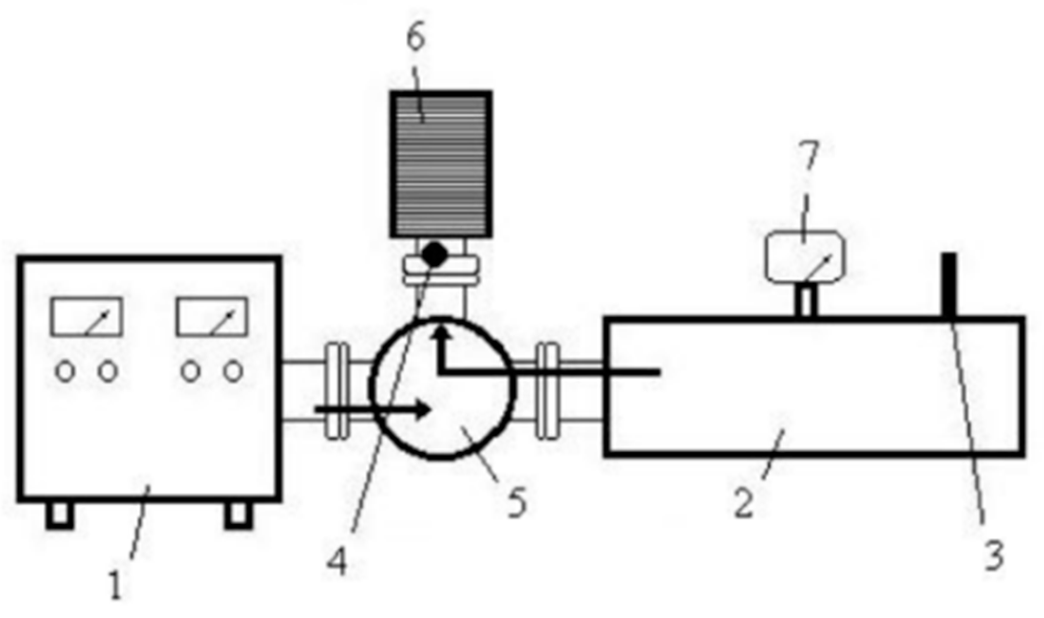
The microwave heating apparatus used in the second method consisted of a resonator chamber, magnetron, circulator, and resonance sensors (Figure 2). The resonator chamber was made from a rectangular waveguide, with one end having a smaller cross-section aperture and the opposite end having a movable wall (plunger). The energy was delivered along the longitudinal axis of the chamber. The main functional elements of the chamber were as follows:
-
The body of the working chamber was made of a piece of copper rectangular waveguide with a standard cross-section of 90 mm × 45 mm. This waveguide had the highest figure of merit for passing electromagnetic energy with a frequency of 2.45 GHz and power of 450 W. The length of the waveguide (235 mm) was selected to be a multiple of the length of the half-wave of the microwave radiation, ensuring that there were an integer number of zones of maximum intensity of the electromagnetic field (in this case, three bundles) formed in the chamber. The upper wall of the chamber had a loading hole in the zone of the middle beam for installing the thermostat with the object to be heated. There was also a hole with a diameter of 4 mm in the side wall of the thermostat and waveguide for temperature control using a pyrometer.
-
The purpose of the aperture is to allow microwave energy to enter the chamber and create a standing wave through the superposition of incoming and reflected waves from the opposite wall. The size of the aperture in the diaphragm is matched to the standing wave coefficient. However, when a dielectric load is placed in the chamber and heated, it can alter the standing wave coefficient and affect the level of matching between the chamber and the generator, causing an increase in the amount of reflected energy from the diaphragm.
-
The short-circuited movable wall, known as the plunger, is a control element used to adjust the length of the chamber. This adjustment can partially or completely align the phases of the waves and form energy bundles of a specific intensity.
The chamber-resonator is designed to achieve maximum matching between the generator, resonator, and load in the ANSYS program; see Figure 3.
In a waveguide-type chamber, there are three zones where the electromagnetic field strength is locally increased (known as beams). These beams occur when the chamber length exceeds three times the wavelength at a frequency of 2.45 GHz. The beam zones are symmetrically located along the motion of the electromagnetic wave and occupy the same volume. Each beam zone has an elliptical cross-section, and the electric field vector E has a “column” shape along the entire height of the chamber, with maximum intensity in the center (up to 10 V/m). The samples were placed in the zones of maximum electromagnetic field intensity.
Microwave heating theoretically has no upper limit for temperature, but the need to retain heat in the product requires the use of thermostats with special properties. Fibrous corundum thermostats, which are transparent to microwave radiation, were used during heating to preserve the heat generated by the samples within the working chamber.
Figure 2. The custom-made microwave furnace: 1—power supply unit and magnetron, 2—reaction chamber, 3—sensor of supplied microwave energy, 4—sensor of reflected microwave energy, 5—circulator, 6—load, 7—optical radiometer. Arrows—the direction of movement of electromagnetic waves.
Ceramics 06 00128 g002
Figure 3. Model of the reaction chamber: 1—diaphragm, 2—movable wall, 3—antinodes of the electric field energy.
Ceramics 06 00128 g003
The phosphors that were obtained underwent a washing process using distilled water to eliminate any excessive chloride.
The composition of the samples that were obtained was determined through X-ray phase analysis, utilizing a Rigaku Smart Lab 3 device. The photoluminescence spectra were measured using an AvaSpec-3648 spectrofluorometer, with an excitation wavelength of 395 nm, which corresponds to the wavelength of the ultraviolet (UV) light-emitting diode (LED) utilized in white light-emitting diode (WLED) fabrication. The brightness of the photoluminescence was quantified using an IL 1700 radiometer. The color rendering index, chromaticity coordinates, and correlated color temperature were measured employing a TKA-VD/01 spectrocolorimeter. The microstructure analysis of the phosphors was conducted using a Quanta 200 scanning electron microscope (SEM).

3. Results and Discussion

3.1. Selection of Thermostat Design for Synthesis in Microwave Furnace

Materials are classified into two types based on their level of microwave absorption:
-
Dielectrics (SiO2, Al2O3, MgO) have a low level of microwave absorption at room temperature, which increases as the temperature rises;
-
Materials with semiconductor properties (SiC, TiO2, CuO) start absorbing microwaves at room temperature [29,30].
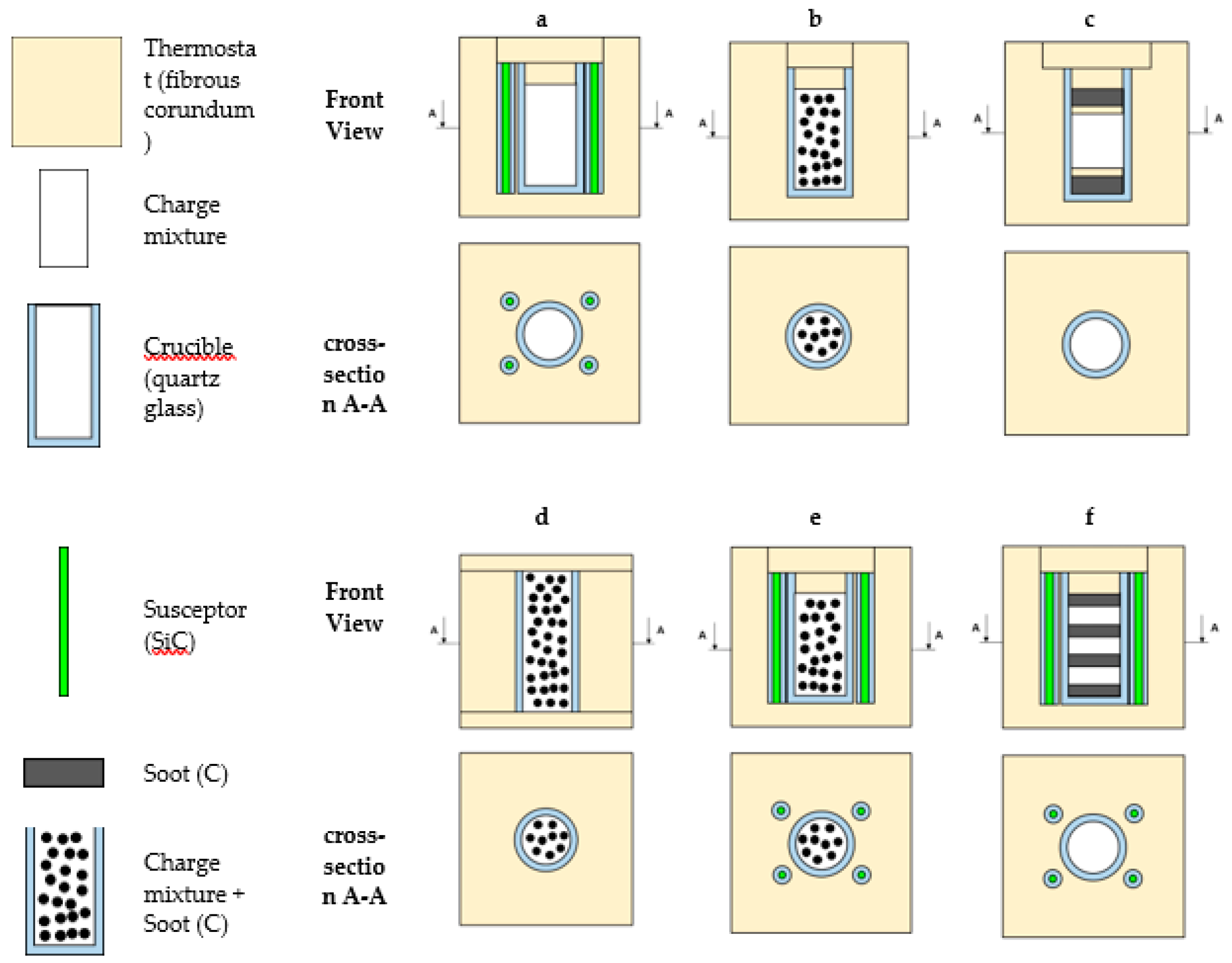
Mixtures used for synthesizing phosphors belong to the first type of materials in terms of microwave absorption. These mixtures are heated using susceptors, which are materials that actively absorb microwave radiation when heated. The first fibrous corundum thermostat design, shown in Figure 4a, includes a charge mixture placed in a quartz crucible surrounded by four quartz crucibles containing a susceptor (SiC). The use of an oxidizing atmosphere in this design resulted in the synthesis of a red luminescent phosphor.
To obtain a white phosphor, it is necessary to convert Eu3+ to Eu2+. This can be achieved by synthesizing in a reducing atmosphere. Carbon black was added to the structure to create a reducing atmosphere for microwave synthesis. It was either placed between the charge layers or mixed with the charge itself (Figure 4b,d,e).
The use of carbon black in designs b, c, and d allowed the reaction volume to be heated without SiC. Carbon black serves two functions: a current collector for heating the system and a reducing agent.
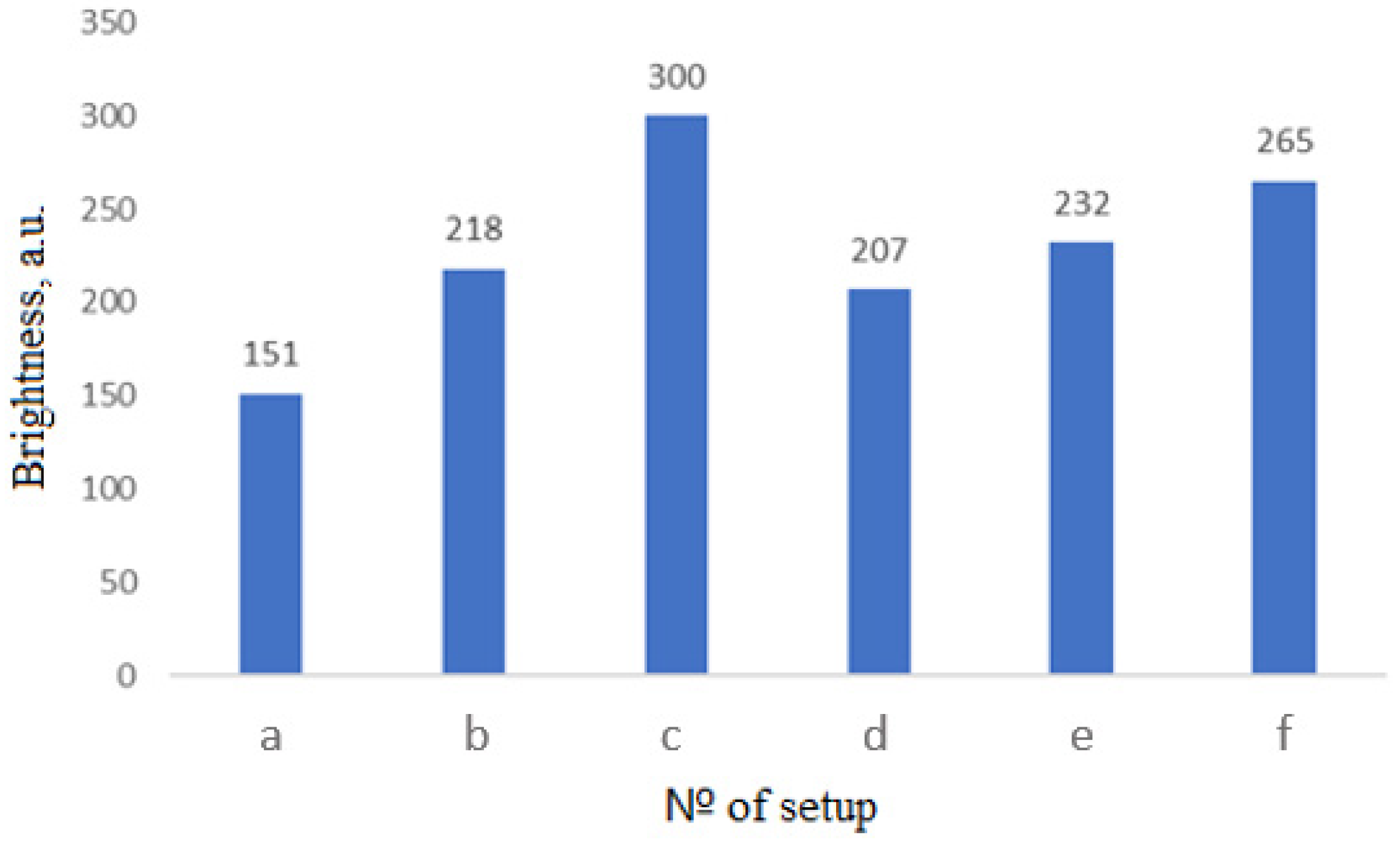
During microwave fusion, the third thermostat design produced samples with the highest brightness, as shown in Figure 5. Therefore, this design was used for all subsequent experiments.

3.2. Choice of Synthesis Technology (Muffle or Microwave Furnace)

The selection of synthesis technology, either a muffle or microwave furnace, results in the formation of a mixture of phosphors. These phosphors include the following: CaSrSiO4:Eu2+, Ca6Sr4Si6O21Cl2:Eu2+, Ca10Si6O21Cl2:Eu2+. X-ray phase analysis confirms that the synthesized phosphors possess a multiphase structure, consisting of CaSrSiO4:Eu2+ (card 72–2260), Ca6Sr4Si6O21Cl2:Eu2+ (card 43–85), and Ca10Si6O21Cl2:Eu2+ (card 48–827). In the phosphors synthesized using the muffle furnace, the CaSrSiO4:Eu2+ phase is predominant. On the other hand, synthesis in the microwave furnace leads to a substantial increase in the yield of chlorosilicate phases. This difference is attributed to the more pronounced interaction between strontium chloride and other reagents, as well as the improved diffusion of chlorine ions into the mixed luminophore structure during synthesis in the microwave furnace.
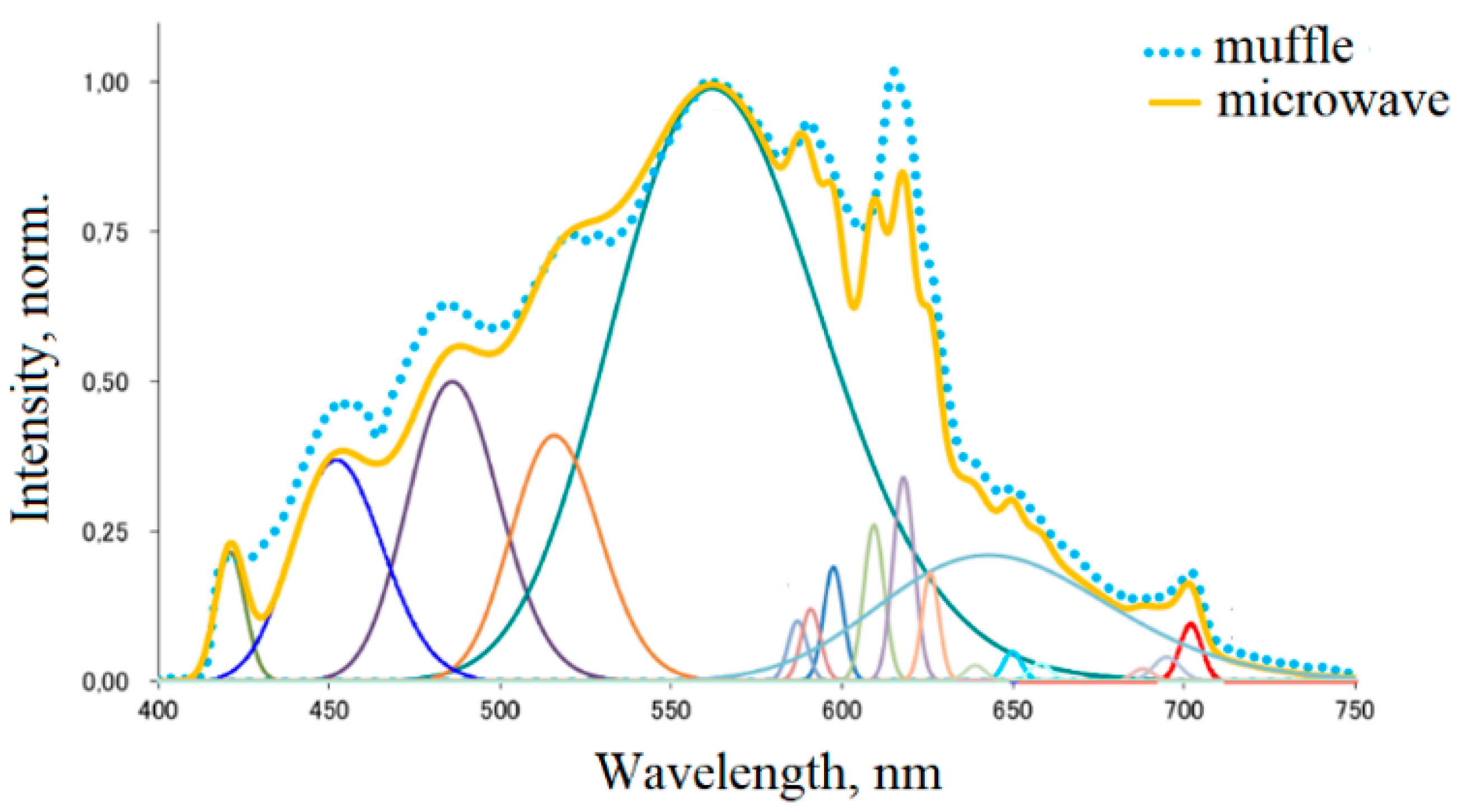
After the synthesis of luminophores in muffle and microwave furnaces, photoluminescence spectra were taken from the samples. The photoluminescence spectrum of luminophores is decomposed into constituent bands in Figure 6 and Table 1.
The observed spectra exhibited slight variations and were analyzed using referenced literature data [11,12,13,14,15,16,17,18,19,20,21,22,31]. These differences included the presence of bands at 452, 485, and 517 nm, situated to the left of the main peak and associated with the 5d-4f transitions of Eu2+ in the predominant phases of the hybrid phosphor, as well as the band at 618 nm, located to the right of the main peak and corresponding to the 5D0-7F2 transition of Eu3+. In the muffle furnace synthesis, the bands at 452 and 485 nm are more pronounced due to an increase in crystallinity and the average size of the coherent scattering region of the chlorosilicate phases. Conversely, in the microwave furnace synthesis, the band at 517 nm is more intense as a result of an increase in crystallinity and the average size of the coherent scattering region of the silicate phase. The band at 618 nm is more pronounced in the muffle furnace synthesis due to the oxidation of a greater number of europium ions.
Table 2 presents the main characteristics of the phosphors synthesized in muffle and microwave furnaces, including phase composition, particle size, intensity, correlated color temperature, color coordinates, color rendering index, etc.
Both samples exhibit luminescence within the “warm” white light region (Figure 7) and share similar characteristics. However, the photoluminescence intensity is significantly higher in samples synthesized in a microwave furnace, presumably due to a more uniform distribution of europium in the phosphors resulting from microwave effects, such as the ponderomotive effect and electrodiffusion.
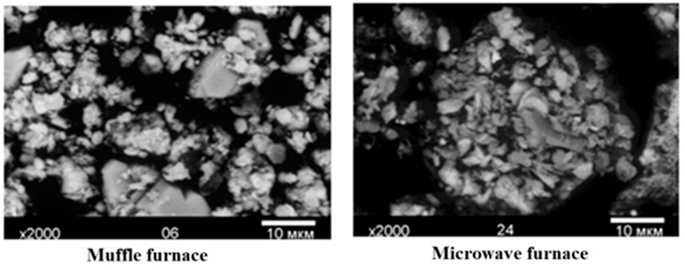
Electron microphotographs (Figure 8) reveal particle sizes ranging from 1 to 5 microns for microwave synthesis and up to 10 microns for synthesis in a muffle furnace. The smaller particle size in the case of microwave furnace synthesis is attributed to lower synthesis temperatures. The particle sizes of the obtained samples meet the requirements for phosphors used in white LEDs.

3.3. Selection of Microwave Synthesis Parameters

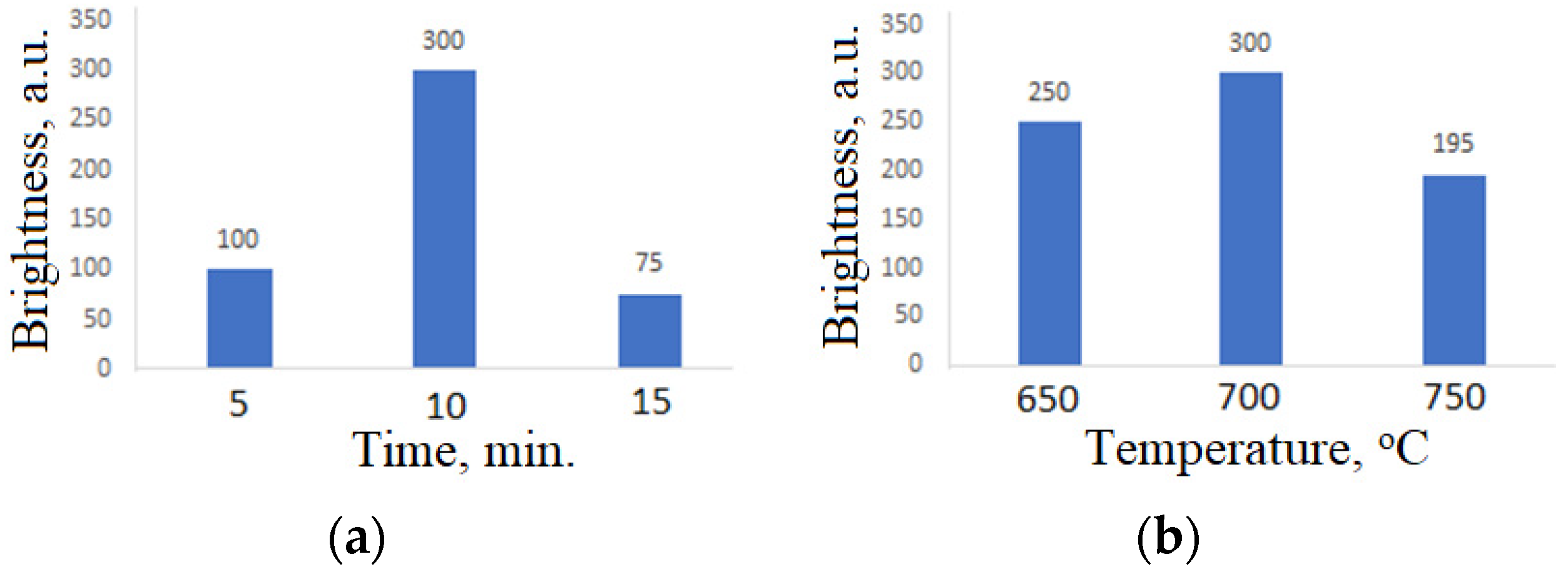
Given that the synthesis carried out in a microwave furnace oven demonstrated enhanced luminophore performance, it is imperative to determine the ideal temperature and duration for synthesis. The samples containing 5.6 mol. % Eu2+ were subjected to incubation at temperatures of 650, 700, and 750 °C for a duration of 10 min. Additionally, incubation at a temperature of 700 °C for 5, 10, and 15 min was conducted. Figure 9 depicts the relationship between the brightness of the hybrid phosphor (CaSrSiO4:Eu2+, Ca6Sr4Si6O21Cl2:Eu2+, Ca10Si6O21Cl2:Eu2+) and the synthesis time and temperature in the microwave furnace. It is noteworthy that the brightest phosphor was obtained after synthesizing at 700 °C for 10 min.

3.4. Selection of Charge Preparation Method

The impact of the charge preparation method (mechanical mixing, sol–gel) on the properties of the blended phosphors was investigated. The mixture that was mechanically mixed with reagents and prepared using the sol–gel method was then synthesized in a microwave furnace at 750 °C for 10 min. The main characteristics of the luminophores are presented in Table 3.
The brightness of the sample acquired using the sol–gel method of charge preparation exhibits a 35% increase in comparison to samples with the same half-width of the photoluminescence spectrum. Additionally, the correlated color temperature of the sol–gel-prepared sample is 400 K higher. Consequently, it is concluded that utilizing sol–gel synthesis in charge preparation enables a 35% enhancement in the brightness of mixed luminophores’ photoluminescence when compared to mechanical mixing. This is attributed to a more uniform distribution and improved integration of the activator into the phosphor base, thereby making the sol–gel method of charge preparation more favorable in the synthesis of mixed luminophores.

3.5. Selection of Chemical Composition in Microwave Synthesis

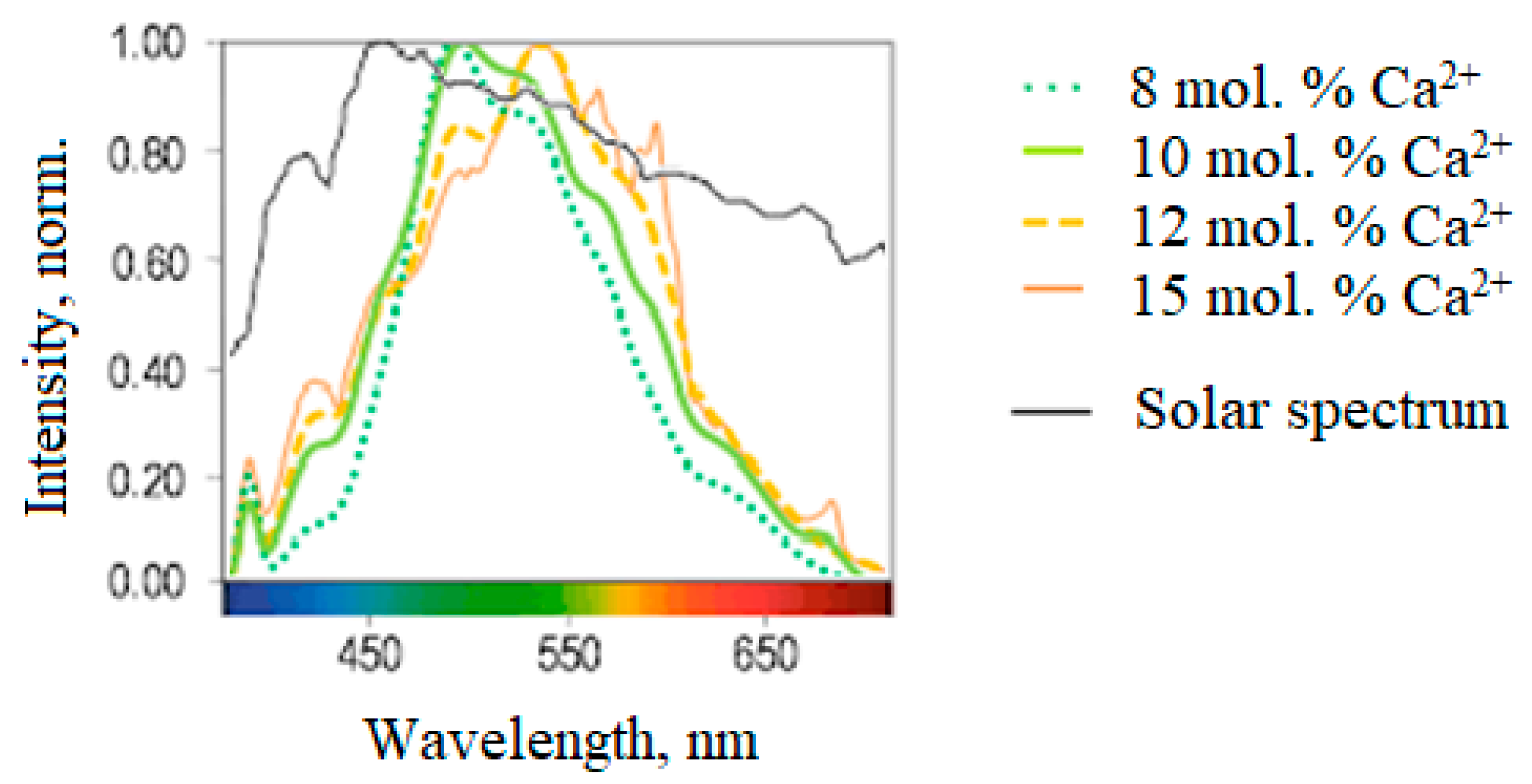
To manipulate the photoluminescence spectrum of the specimens, the level of carbon black was doubled to prevent the introduction of trivalent europium and decrease the proportion of Ca2+ in the charge. Consequently, the 597 to 702 nm bands associated with Eu3+ transitions in CaSrSiO4 disappeared from the spectrum, and the spectrum itself shifted towards shorter wavelengths, a consequence of increased CaSrSiO4:Eu2+ content in the phosphor mixture (Figure 10). The optimum concentration of Ca2+ in the charge was determined to be 10 mol. %, resulting in a color rendering index of 93 (Table 4).
It is observed that the color rendering index of the synthesized hybrid phosphors achieves the highest value at a Ca2+ concentration of 10 mol. % in the charge mixture, attributable to the alteration of the phosphor’s phase composition. Therefore, the optimal phase composition, CaSrSiO4:Eu2+: Ca6Sr4Si6O21Cl2:Eu2+: Ca10Si6O21Cl2:Eu2+ = 50:29:21, is suitable for use in UV-excited white light-emitting diodes with wide emission spectra and a high color rendering index.
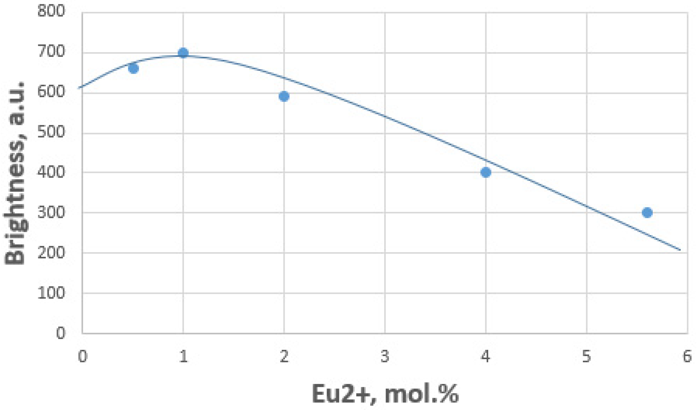
Subsequently, the optimal concentration of Eu2+ in the phosphor was determined by synthesizing all samples at 700 °C for 10 min. The most luminous samples of the hybrid phosphor were obtained at a europium concentration of 1 mol. % (Figure 11). Increasing the activator quantity beyond 1 mol. % resulted in a decrease in brightness due to concentration quenching. The spectral characteristics of the samples were unchanged.
Table 4 presents the characteristics of hybrid phosphors (CaSrSiO4:Eu2+, Ca6Sr4Si6O21Cl2:Eu2+, Ca10Si6O21Cl2:Eu2+) that were synthesized from charge mixtures with varying Ca2+ concentrations.
It is established that the ionic radius of Eu2+ is larger than that of Ca2+ but approximately equal to that of Sr2+ [32]. As a result, one can hypothesize that Eu2+ is more likely to substitute Sr2+ rather than Ca2+ in phosphor matrices (CaSrSiO4 and Ca6Sr4Si6O21Cl2).
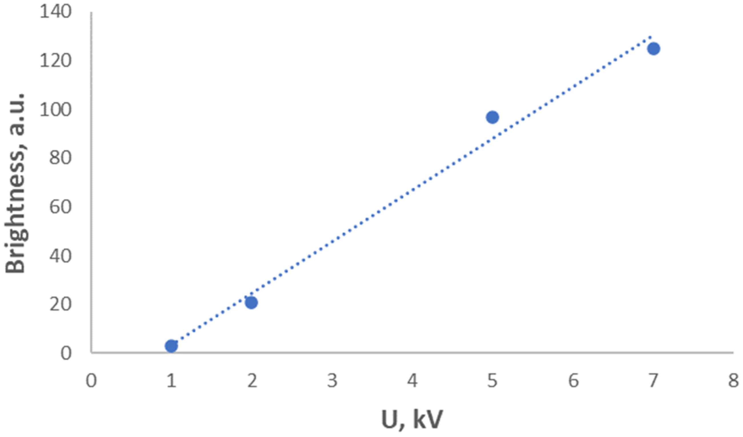
The cathodoluminescence of the synthesized mixed phosphor was studied. The brightness dependence on the voltage at the anode is linear (Figure 12), and the color of the luminescence is also a “warm” white, which allows for the use of the hybrid phosphor (CaSrSiO4:Eu2+, Ca6Sr4Si6O21Cl2:Eu2+, Ca10Si6O21Cl2:Eu2+) in cathodoluminescent light sources.
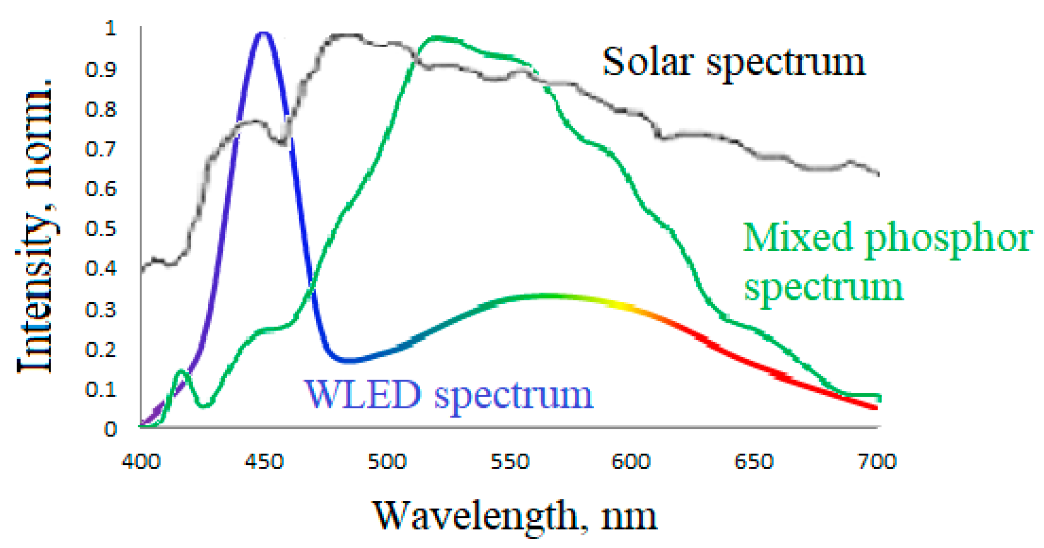
Thus, a methodology was devised for the amalgamation of hybrid phosphors (0.5 CaSrSiO4:Eu2+, 0.29 Ca6Sr4Si6O21Cl2:Eu2+, 0.21 Ca10Si6O21Cl2:Eu2+) utilizing a microwave furnace, enabling attainment of the traits of specimens that are typically only achievable over an extended duration under elevated temperatures in a muffle furnace (i.e., elevated luminosity and elevated color rendering index). The emission spectrum of a white light-emitting diode (WLED) fabricated using the aforementioned phosphor synthesis technique more closely approximates the solar spectrum in comparison to a conventional WLED (refer to Figure 13).

4. Conclusions

  • A one-step method has been developed for synthesizing a new hybrid CSSC phosphor (0.5 CaSrSiO4:Eu2+: 0.29 Ca6Sr4Si6O21Cl2:Eu2+: 0.21 Ca10Si6O21Cl2:Eu2+) using microwave heating. The phosphor synthesized under optimal conditions exhibits a wide luminescence spectrum similar to sunlight, resulting in a high color rendering index and warm white luminescence color in WLEDs based on it.
  • The sol–gel method for preparing the charge mixture for the hybrid phosphor (0.5 CaSrSiO4:Eu2+, 0.29 Ca10Si6O21Cl2:Eu2+, 0.21 Ca6Sr4(Si2O7)3Cl2:Eu2+) allows for 35% higher luminescence brightness compared to the solid-phase method, due to a more uniform distribution of the activator.
  • A CSSC phosphor can be used in cathodoluminescent white light sources.

Author Contributions

Conceptualization, M.S., I.T. and K.H.; methodology, M.S., I.T., K.H. and H.K.; software, M.S., M.K., A.D., I.T., K.H. and H.K.; validation, M.S., I.T. and K.H.; formal analysis, M.S., M.K., I.T., K.H. and H.K.; investigation, M.S., M.K., I.T., K.H. and H.K.; resources, M.S., M.K., I.T., K.H. and H.K.; data curation, M.S., M.K., I.T., K.H. and H.K.; writing—original draft preparation, M.S., M.K., I.T., K.H. and H.K.; writing—review and editing, M.S., A.D., M.K., I.T., K.H. and H.K.; visualization, M.S., M.K., A.D., I.T., K.H. and H.K.; supervision, M.S., I.T., K.H. and H.K.; project administration, M.S., I.T., K.H. and H.K.; funding acquisition, M.S., I.T., K.H. and H.K. All authors have read and agreed to the published version of the manuscript.

Funding

The research was carried out within the state assignment of the Ministry of Science and Higher Education of the Russian Federation (theme no. 0081-2022-0001). Author Keskinova M.V. received research support from an MEXT scholarship in Japan.

Institutional Review Board Statement

Not applicable.

Informed Consent Statement

Not applicable.

Data Availability Statement

Data supporting this study are not publicly available due to commercial reasons. Please contact our research group: [email protected].

Conflicts of Interest

The authors declare no conflict of interest.

References

  1. Geiger, C.A. Garnet: A Key Phase in Nature, the Laboratory, and Technology. Elements 2013, 9, 447–452. [Google Scholar] [CrossRef]
  2. Berends, A.C.; van de Haar, M.A.; Krames, M.R. YAG:Ce3+ Phosphor: From Micron-Sized Workhorse for General Lighting to a Bright Future on the Nanoscale. Chem. Rev. 2020, 120, 13461–13479. [Google Scholar] [CrossRef] [PubMed]
  3. Kozaki, T.; Koga, S.; Toda, N.; Noguchi, H.; Yasukouchi, A. Effects of short wavelength control in polychromatic light sources on nocturnal melatonin secretion. Neurosci. Lett. 2008, 439, 256–259. [Google Scholar] [CrossRef]
  4. Rea, M.S.; Figueiro, M.G.; Bierman, A.; Bullough, J.D. Circadian light. J. Circadian Rhythm. 2010, 8, 2. [Google Scholar] [CrossRef] [PubMed]
  5. Yadav, D.; Kumar, U.; Upadhyay, S. Study of structural, electrical, and photoluminescent properties of SrCeO3 and Sr2CeO4. J. Adv. Ceram. 2019, 8, 377–388. [Google Scholar] [CrossRef]
  6. Zhang, Z.; Sun, L.; Devakumar, B.; Liang, J.; Wang, S.; Sun, Q.; Dhoble, S.J.; Huang, X. Novel highly luminescent double-perovskite Ca2GdSbO6:Eu3+ red phosphors with high color purity for white LEDs: Synthesis, crystal structure, and photoluminescence properties. J. Lumin. 2020, 221, 117105. [Google Scholar] [CrossRef]
  7. Sharma, G.; Poddar, P. Organic–Inorganic Hybrids for White-Light Phosphors. In Hybrid Phosphor Materials; Springer: Cham, Switzerland, 2022; pp. 105–118. [Google Scholar] [CrossRef]
  8. Xu, D.; Liu, J.; Sun, C.; Wang, L.; Han, J.; Tao, J.; Zhang, H.; Wei, T.; Su, S.; Liu, X.; et al. Copper iodide-based hybrid phosphors for eco-friendly white-light-emitting diodes. J. Lumin. 2022, 244, 118733. [Google Scholar] [CrossRef]
  9. Ahn, Y.N.; Kim, K.D.; Anoop, G.; Kim, G.S.; Yoo, J.S. Design of highly efficient phosphor-converted white light-emitting diodes with color rendering indices (R1 − R15) ≥ 95 for artificial lighting. Sci. Rep. 2019, 9, 16848. [Google Scholar] [CrossRef]
  10. Vasina, O.U. Sol-Gel Phosphors on the Basis of Silicates of Second Group Element. Ph.D. Thesis, D. Mendeleyev University of Chemical Technology of Russia, Moscow, Russia, 2003. [Google Scholar]
  11. Park, J.K.; Choi, K.J.; Kim, C.H.; Park, H.D.; Choi, S.Y. Optical Properties of Eu2+-Activated Sr2SiO4 Phosphor for Light-Emitting Diodes. Electrochem. Solid-State Lett. 2004, 7, H15–H17. [Google Scholar] [CrossRef]
  12. Kim, J.S.; Jeon, P.E.; Choi, J.C.; Park, H.L. Emission color variation of M2SiO4: Eu2+ (M = Ba, Sr, Ca) phosphors for light-emitting diode. Solid State Commun. 2005, 133, 187–190. [Google Scholar] [CrossRef]
  13. Barry, T.L. Fluorescence of Eu2+ activated phase in binary alkaline earth orthosilicate systems. J. Electrochem. 1968, 115, 1181–1184. [Google Scholar] [CrossRef]
  14. Wang, J.; Qin, L.; Huang, Y.; Wei, D.; Seo, H.J. Color centers and dynamic emission of Eu2+ ion doped halosilicate Ca10Si6O21Cl2. Appl. Phys. 2014, 115, 1215–1221. [Google Scholar] [CrossRef]
  15. Li, Z.; Gao, S.; Chen, X.; Yu, Q. Synthesis and luminescence properties of green phosphors Ca6Sr4(Si2O7)3Cl2:Eu2+ for white light emitting diodes. J. Lumin. 2012, 132, 1497–1500. [Google Scholar] [CrossRef]
  16. Xia, Z.; Sun, J.; Laamanen, T. Luminescence of Eu2+ in alkali earth chlorosilicate phosphor and their color-tunable properties. Opt. Mater. 2006, 28, 524–529. [Google Scholar] [CrossRef]
  17. Sasaki, Y.; Daicho, H.; Auyagi, S.; Sawa, H. Phosphor and Light-Emitting Device. U.S. Patent No. 0256222, 11 October 2012. [Google Scholar]
  18. Keskinova, M.V.; Ogurtsov, K.A.; Sychov, M.M.; Kolobkova, E.V.; Turkin, I.A.; Nakanishi, Y.; Hara, K. Synthesis of chlorine-silicate phosphors for white light-emitting diodes. Adv. Mater. Res. 2015, 1117, 48–51. [Google Scholar] [CrossRef]
  19. Turkin, I.A.; Keskinova, M.V.; Sychov, M.M.; Ogurtsov, K.A.; Hara, K.; Nakanishi, Y.; Shilova, O.A. Microwave Synthesis of Eu-doped Silicate Phosphors. In Proceedings of the JJAP Conference Proceedings 14th International Conference on Global Research and Education, Inter-Academia 2015, Hamamatsu, Japan, 28–30 September 2015; Volume 4, pp. 011108–011114. [Google Scholar]
  20. Turkin, I.A.; Keskinova, M.V.; Sychov, M.M.; Ogurtsov, K.A.; Hara, K.; Nakanishi, Y.; Shilova, O.A. Cathodoluminescent Properties and Particle Morphology of Eu-Doped Silicate Phosphors Synthesized in Microwave Furnace. Adv. Intell. Syst. Comput. 2017, 519, 339–346. [Google Scholar]
  21. Keskinova, M.V.; Eremeeva, M.A.; Sychev, M.M. Single-Stage Microwave Synthesis of Mixed Luminophor for Light Sources. Glass Phys. Chem. 2021, 47, 360–365. [Google Scholar] [CrossRef]
  22. Keskinova, M.V.; Verzunov, P.P.; Turkin, I.A.; Sychev, M.M. Activation of Zr0.95−xY0.05O2:Eu3+x by heat treatment in an electromagnetic field of the microwave range. Glass Phys. Chem. 2019, 45, 501–505. [Google Scholar] [CrossRef]
  23. Rubakov, K.I.; Semenov, V.E. A non-thermal vacancy drift mechanism of plastic deformation of grains in ceramics microwave sintering. MRS Online Proc. Libr. 1994, 347, 661–666. [Google Scholar] [CrossRef]
  24. Bonifas, C.J.; Marconnet, J. Perry; Microwave–induced mass transport enhancement in nano-porous aluminum oxide membranes. J. Microw. Power Electromagn. Energy 2008, 42, 13–22. [Google Scholar] [CrossRef] [PubMed]
  25. Janne, M.A.; Kimrey, H.D.; Kiggins, J.O. Microwave proceedings of ceramics: Guide-lines used of the Oak Ridge Laboratory. MRS Online Proc. Libr. 1992, 269, 173–185. [Google Scholar] [CrossRef]
  26. Unifantowicz, P.; Vaucher, S.; Lewandowska, M.; Kurzydłowski, K.J. Mechanism of SiC crystals growth on {100} and {111} diamond surfaces upon microwave heating. Mater. Charact. 2010, 61, 648–652. [Google Scholar] [CrossRef]
  27. Ayyappadas, C.; Annamalai, A.R.; Agrawal, D.K.; Muthuchamy, A. Conventional and microwave assisted sintering of copper-silicon carbide metal matrix composites: A comparison. Metall. Res. Technol. 2017, 114, 506–516. [Google Scholar] [CrossRef]
  28. Madhan, M.; Prabhakaran, G. Microwave versus conventional sintering: Microstructure and mechanical properties of Al2O3–SiC ceramic composites. Boletín Soc. Española Cerámica Vidr. 2018, 58, 14–22. [Google Scholar] [CrossRef]
  29. Sutton, W.H. Microwave Firing of High–Alumina Ceramics. MRS Online Proc. Libr. 1992, 269, 3–20. [Google Scholar] [CrossRef]
  30. Spotz, M.S.; Skamser, D.J.; Jonson, D.L. Thermal stability of ceramic materials in microwave heating. J. Am. Ceram. Soc. 1995, 78, 1041–1048. [Google Scholar] [CrossRef]
  31. Kumar, U.; Upadhyay, S.; Alvi, P.A. Study of reaction mechanism, structural, optical and oxygen vacancy-controlled luminescence properties of Eu-modified Sr2SnO4 Ruddlesden popper oxide. Phys. B Condens. Matter 2020, 604, 412708. [Google Scholar] [CrossRef]
  32. Tezuka, S.; Sato, Y.; Komukai, T.; Takatsuka, Y.; Kato, H.; Kakihana, M. Eu2+-Activated CaSrSiO4: A New Red-Emitting Oxide Phosphor for White-Light-Emitting Diodes. Appl. Phys. Express 2013, 6, 072101. [Google Scholar] [CrossRef]
Figure 1. Emission spectra of CaSrSiO4:Eu2+ (green), Ca6Sr4Si6O21Cl2:Eu2+ (yellow), and Ca10Si6O21Cl2:Eu2+ (blue) phosphors.
Ceramics 06 00128 g001
Figure 4. Designs of thermostats for synthesis of phosphors in microwave furnace: (a)—oxidizing atmosphere, with a susceptor; (b,d)—reducing atmosphere, soot in the charge, without susceptor; (c)—reducing atmosphere, soot above and below the charge, without susceptor; (e)—reducing atmosphere, soot in the charge, with a susceptor; (f)—reducing atmosphere, soot above and below the charge, with a susceptor.
Ceramics 06 00128 g004
Figure 5. Brightness of samples in reference units (y.e.) synthesized in different facilities.
Ceramics 06 00128 g005
Figure 6. Photoluminescence spectra of hybrid phosphor (CaSrSiO4:Eu2+, Ca6Sr4Si6O21Cl2:Eu2+, Ca10Si6O21Cl2:Eu2+) synthesized in microwave and muffle furnaces. Unmarked curves are components of the photoluminescence spectrum bands of the developed phosphors (presented in Table 1).
Ceramics 06 00128 g006
Figure 7. Luminescence of samples synthesized in muffle and microwave ovens in color coordinates.
Ceramics 06 00128 g007
Figure 8. Electron microphotographs of the samples.
Ceramics 06 00128 g008
Figure 9. The brightness of the samples was influenced by two factors: (a) the duration of synthesis at a temperature of 700 °C and (b) the temperature of synthesis.
Ceramics 06 00128 g009
Figure 10. Photoluminescence spectra of synthesized samples with different concentrations of Ca2+.
Ceramics 06 00128 g010
Figure 11. Brightness hybrid phosphor (0.5 CaSrSiO4:Eu2+, 0.29 Ca6Sr4Si6O21Cl2:Eu2+, 0.21 Ca10Si6O21Cl2:Eu2+) at different concentrations of europium.
Ceramics 06 00128 g011
Figure 12. Dependence of the brightness of cathodoluminescence on anode voltage.
Ceramics 06 00128 g012
Figure 13. Photoluminescence spectra of sunlight, WLED based on YAG:Ce, and mixed phosphor.
Ceramics 06 00128 g013
Table 1. The bands found in the hybrid phosphor (CaSrSiO4:Eu2+, Ca6Sr4Si6O21Cl2:Eu2+, Ca10Si6O21Cl2:Eu2+).
№ of the BandWavelength, nmElectron TransitionsPhases
14215d-4f Eu2+SrCl2
24525d-4f Eu2+Ca10Si6O21Cl2
34865d-4f Eu2+Ca6Sr4Si6O21Cl2
45165d-4f Eu2+CaSrSiO4
55625d-4f Eu2+Ca6Sr4Si6O21Cl2
66435d-4f Eu2+CaSrSiO4
7–18597–7024f-4f Eu3+CaSrSiO4
Table 2. The main characteristics of hybrid phosphors (CaSrSiO4:Eu2+, Ca6Sr4Si6O21Cl2:Eu2+, Ca10Si6O21Cl2:Eu2+).
CharacteristicsSynthesis Conditions
Microwave Furnace,
10 min, 750 °C
Muffle Furnace, N2:H2
2.5 h, 950 °C
Phase composition (CaSrSiO4:Eu2+, Ca6Sr4Si6O21Cl2:Eu2+, Ca10Si6O21Cl2:Eu2+), %40, 27, 3345, 26, 29
Particle size, µm1–51–10
FWHM, nm155160
Intensity, a.u.30102135
Correlated color temperature, K37003440
Color coordinatesx = 0.401x = 0.417
Color rendering indexy = 0.408y = 0.418
Table 3. Characteristics of samples.
Mixing MethodIntensity, a.u.Full Width at Half Maximum, nmCorrelated Color Temperature, K
Mechanical mixing7001113800
Sol–gel synthesis9451114200
Table 4. Hybrid SCSC phosphors’ (CaSrSiO4:Eu2+, Ca6Sr4Si6O21Cl2:Eu2+, Ca10Si6O21Cl2:Eu2+) characteristics with different Ca2+ concentrations.
Hybrid Phosphor CharacteristicsCa2+ Concentration in Charge Mixture
8 mol. %10 mol. %12 mol. %15 mol. %
Phase composition (CaSrSiO4:Eu2+, Ca6Sr4Si6O21Cl2:Eu2+, Ca10Si6O21Cl2:Eu2+), %57, 33, 1050, 29, 2142, 28, 3040, 27, 33
Color rendering index87938583
Disclaimer/Publisher’s Note: The statements, opinions and data contained in all publications are solely those of the individual author(s) and contributor(s) and not of MDPI and/or the editor(s). MDPI and/or the editor(s) disclaim responsibility for any injury to people or property resulting from any ideas, methods, instructions or products referred to in the content.