Article

Furnace Testing and Validation of a Hybrid Cooling Approach for Enhanced Turbine Blade Protection with a Thermal Barrier Coating in Advanced Gas Turbines

by
Salmi Mohd Yunus
1,2,*,
Abreeza Manap
1,
Meenaloshini Satgunam
1,
Savisha Mahalingam
3 and
Nurfanizan Mohd Afandi
1
1
Department of Mechanical Engineering, College of Engineering, Universiti Tenaga Nasional, Jalan IKRAM-UNITEN, Kajang 43000, Selangor, Malaysia
2
Materials Engineering and Testing Group, TNB Research Sdn Bhd, Kawasan Institusi Penyelidikan, No. 1 Lorong Ayer Itam, Kajang 43000, Selangor, Malaysia
3
Institute of Sustainable Energy, Universiti Tenaga Nasional, Jalan IKRAM-UNITEN, Kajang 43000, Selangor, Malaysia
*
Author to whom correspondence should be addressed.
Ceramics 2024, 7(4), 1340-1364; https://doi.org/10.3390/ceramics7040088
Submission received: 8 August 2024 / Revised: 11 September 2024 / Accepted: 20 September 2024 / Published: 27 September 2024

Abstract

:
Hybrid turbine blade protection systems, which combine thermal barrier coatings (TBCs) and cooling mechanisms, are essential for safeguarding turbine blades in advanced gas turbine applications. However, conventional furnace evaluation methods are inadequate for accurately simulating the complex thermal conditions experienced by TBCs in these environments. Initial testing revealed substantial degradation of TBCs when subjected to high temperatures without the necessary cooling support. To address this limitation, the furnace setup was modified to incorporate a cooling air system. This system channeled 400 °C air to the back surface of the TBC while subjecting the front to 1400 °C furnace air, effectively replicating the thermal gradient encountered in hybrid protection systems. The modified furnace setup demonstrated a remarkable improvement in the performance of yttria-stabilized zirconia TBCs. By cooling the back surface of the TBC, the metal substrate temperature decreased, thereby improving the thermal gradient on the coating and its durability. The thermal gradient achieved by the modified furnace was verified to simulate accurately the conditions experienced by TBCs in advanced gas turbines. The conventional furnace setup, lacking a cooling mechanism, overestimated the heat transfer on the TBCs, leading to inaccurate results. The modified furnace, with its integrated cooling system, more accurately simulated the conditions experienced by TBCs in real-world advanced gas turbine applications and more reliably assessed their performance.

1. Introduction

Gas turbines operate under extreme conditions, where high temperatures are necessary for efficient energy conversion [1]. Turbine blades are exposed to hot gases, which can exceed the melting point of the blade material [2]. Cooling technologies such as thermal barrier coating (TBC) and internal cooling are employed to prevent failure [3]. TBC provides a thermal insulation layer that reduces the heat transfer to the blade, whereas internal cooling channels allow the circulation of a cooling fluid, usually air, to absorb and dissipate heat [4]. For example, in a gas turbine power plant, turbine blades operate in an environment where combustion gases can reach temperatures above 1500 °C. The effectiveness of the TBC and internal cooling in maintaining the blade material’s temperature below critical levels directly influences the turbine’s reliability and lifespan. Accurate prediction of metal temperature distribution ensures that the cooling is sufficient to protect the blade from thermal degradation and failure. Hybrid turbine blade protection systems are a common solution used in advanced gas turbine applications to protect turbine blades from high temperatures and oxidation [5]. These systems typically use a combination of TBC and cooling systems to provide adequate protection.
Combining the TBC and cooling system offers a highly effective protection system for turbine blades [2]. The TBC reduces the heat that reaches the blade surface [5]. By contrast, the cooling system further reduces the temperature of the blade surface and helps prevent damage from high temperatures and oxidation [3]. Consequently, this hybrid protection system provides a higher level of protection against high temperatures and thermal stresses of advanced gas turbine operating conditions, which can extend the service life of gas turbine blades [6]. Therefore, this can reduce maintenance costs by increasing the durability of the turbine blades, which lowers the frequency of replacement or repair. Furthermore, the hybrid system can improve gas turbine engines’ safety by reducing the risk of blade failure. Several studies have discussed the application of TBC on superalloy components with the assistance of the cooling air system [7,8]. In addition, Uysal et al. [9] discussed the effectiveness of cooling air associated with the TBC on a blade in improving efficiency.
The conventional TBC topcoat, yttria-stabilized zirconia (YSZ), undergoes phase transformations during gas turbine heating and cooling cycles and leads to spallation [10]. YSZ, commonly doped with yttrium, faces limitations in advanced gas turbines due to sintering and hot corrosion; thus, it is preferable for use under operating temperature exposures below its phase transformation temperature of approximately 1170 °C [11,12,13]. The t′-phase of YSZ transforms to t- and/or c-phase under prolonged operating temperatures beyond 1200 °C (static condition) and becomes considerable where the t-phase transforms to the monoclinic (m) phase and leads to 3–5% volume expansion in cyclic conditions and/or during cooling, thus resulting in TBC cracking [14,15,16]. Xiao et al. [17] reported that TBC failure from the conducted isothermal oxidation test up to 1100 °C does not represent the failure of the actual turbine blade associated with the blade’s internal cooling, which has been proven through their simulation works.
Commercial furnaces have been widely used for isothermal oxidation tests, but they also fall short of imitating the cooling air effect in advanced gas turbine applications. Examples include studies by Bobzin et al. [18], Chen et al. [19], Essa et al. [20], Goral et al. [21], Izadinia et al. [22], Paraschiv et al. [23], Yang et al. [24], Jonnalagadda et al. [25], Karaoglanli et al. [26], and Vorkotter et al. [27] conducted at various temperatures up to 1200 °C. Researchers argue that for accurate simulation of TBC behavior in advanced gas turbines, high temperatures, and cooling systems need to be incorporated into test rig designs because existing approaches lack completeness in representing real-world operating conditions. For example, in their recent studies, Qiannan et al. [28] recommended improving TBC characterization, specifically the accuracy of thermally grown oxide (TGO) thickness prediction, by considering the temperature gradient factor. This recommendation stems from their use of a commercial electric furnace with a limited testing temperature of 1100 °C. Previously, various test rigs were identified to simulate TBC under steady-state conditions [6]. While some researchers, such as Fan et al. [29] and Nau et al. [30], employed custom-made test rigs to expose TBC to high temperatures, a consensus is that these setups lack the representation of advanced gas turbine operating conditions due to the absence of cooling systems. These examples highlight the need for comprehensive test rig designs incorporating high temperatures and cooling systems to simulate TBC behavior accurately in advanced gas turbine conditions. A commercial furnace can simplify that overlooking the thermal gradient fails to replicate the complex environmental factors affecting TBC, potentially leading to inaccurate or overly conservative estimates of their behavior and lifespan. Therefore, while commercial furnaces may offer quicker results, the insights gained from custom furnaces with better thermal gradient capabilities are invaluable for optimizing TBC design and performance, ultimately leading to more reliable test facilities for advanced gas turbine operation.
Many studies have used test rigs to simulate TBC under high-temperature steady-state and cyclic conditions. However, only custom-made test rigs for TBC simulation under cyclic conditions apply the cooling air system to assist TBC in performing advanced gas turbine applications. Thermal cycling is used to predict the TBC behaviors in the peak load of a gas turbine, where more starts are needed upon load demand, and involves many cycles of heating during start-up and cooling during stop [31]. While these test rigs are essential for understanding the effects of thermal cycling on TBCs, a critical need also exists for test rigs to simulate steady-state conditions. Testing under steady-state conditions is necessary to evaluate how TBCs respond to sustained thermal loads, representing the base-load gas turbine operation [32]. Tests under steady-state conditions can provide insights into the gradual degradation mechanisms that occur over extended periods and enable more accurate predictions of TBC lifespan and performance under the base load operation. To simulate the effects of steady-state operation on TBC accurately, employing a customized test rig is essential. This rig utilizes a cooling air system to replicate conditions similar to those in cyclic simulations, providing valuable insights for TBC performance evaluation under steady-state operation. This study evaluates the conventional TBC system using the modified furnace to achieve thermal gradient enhancement. A customized test rig incorporating a cooling air system is crucial for accurately simulating steady-state conditions and evaluating TBC performance under sustained thermal loads similar to base-load gas turbine operations.

2. Modified Furnace for Thermal Gradient Enhancement

The exact thermal gradient of the TBC system is critical in ensuring the Ni-based substrate is not exposed to excessively high temperatures, which can lead to severe degradation. In actual gas turbine operation, the thermal gradient across the TBC system is carefully managed to protect the underlying substrate from the extreme heat generated during operation. Figure 1 is a schematic diagram of the simplified temperature exposures and the direction of hot and cooling gas flow to illustrate the substantial differences between the actual gas turbine exposures and the commercial furnace. In a gas turbine, the TBC system creates a temperature gradient that effectively insulates the Ni-based substrate from the highest temperatures [33]. The topcoat of the TBC absorbs and dissipates a considerable portion of the heat, whereas the bond coat provides additional thermal and oxidative protection [34]. This layered defense mechanism ensures the substrate remains at a low, manageable temperature to prolong its lifespan and maintain its structural integrity.
In a commercial furnace setup, the thermal gradient is often less precisely controlled, leading to higher temperature exposure across the entire TBC system, including the Ni-based substrate. Figure 1 shows that the substrate consequently experiences higher temperatures than it would under actual operating conditions in a gas turbine. The commercial furnace fails to replicate the protective thermal gradient of the hybrid protection system used in advanced gas turbines, which results in accelerated degradation of the bond coat and the substrate. This lack of a proper thermal gradient in the commercial furnace has several detrimental effects. When exposed to high temperatures, the Ni-based substrate undergoes rapid oxidation and phase transformations that compromise its mechanical properties [35]. Additionally, the bond coat suffers from accelerated oxidation and depletion of essential elements such as Cr, forming mixed oxides and voids [24]. These changes contribute to the interspallation of the bond coat, where it detaches from the substrate and further undermines the integrity of the TBC system. The modified furnace, designed to imitate the thermal gradient, improves the TBC system’s overall performance and longevity under high-temperature conditions.
To simulate better the conditions experienced by the TBC system in advanced gas turbines, modifications were made to a commercial furnace, including the installation of a cooling air system. This modification allowed the furnace to replicate the prolonged exposure of TBC-coated components to operational temperatures of 1400 °C, similar to those in gas turbines. The cooling air system was designed to direct cooling air toward the back surface of the TBC-coated specimen to create a thermal gradient that imitates actual turbine thermal exposures. In the modified furnace setup, the TBC specimen was held so that only the surface of the TBC was exposed to the furnace air at 1400 °C. The cooling air system supplied air at a lower temperature of 400 °C to the back surface of the TBC specimen. This arrangement simulated the hybrid cooling protection mechanism used in gas turbines, where the front surface of the TBC was exposed to high temperatures while the backside was kept cooler to prevent the Ni-based substrate from overheating. Figure 2 illustrates the thermal exposure conditions of the TBC system in the modified furnace during an isothermal oxidation test. This setup ensured that the TBC experienced a temperature gradient similar to that in an actual turbine to provide more accurate insights into the performance and degradation behavior of the TBC system under realistic operational conditions.
Various equipment and devices were carefully selected and arranged as auxiliary components in the modified furnace setup to achieve this configuration. These components are essential for maintaining the desired thermal conditions and ensuring the accurate simulation of turbine-like environments. Figure 3 provides a detailed schematic of the modified furnace setup and shows the arrangement of these auxiliary parts. Table 1 lists the selected parts and their specific functions within the modified furnace system. For instance, temperature controllers, air flow regulators, and cooling air supply mechanisms are included to control and monitor precisely the thermal environment experienced by the TBC specimen. Each part plays a crucial role in maintaining the thermal gradient and ensuring the cooling air system operates effectively to protect the TBC and the underlying substrate. The modified furnace setup includes several key components to simulate the thermal conditions of advanced gas turbines accurately. An air blower provides air at a controlled flow rate, whereas an electric heater heats this air to 400 °C. The commercial furnace, modified to hold the TBC-coated specimen and the cooling air source, supplies air at 1400 °C to the TBC surface. A hot air blower pipe routes the cooling air from the air blower to the back surface of the TBC-coated specimen, ensuring the cooling air is safely exhausted after use. This configuration maintains a realistic thermal gradient, protecting the TBC system and underlying substrate during testing.
In actual gas turbine operation, gas turbines are designed to maintain a constant temperature at the turbine inlet to maximize the turbine’s efficiency and performance [36]. Therefore, for the isothermal oxidation test, the furnace temperature represented the hot gas temperature, which was assumed constant throughout the exposures. A mock-up test was conducted to determine the suitable cooling air flow rate for the isothermal oxidation test—the actual cooling air mass flow rate in the advanced gas turbine unit was 12 kg/s. The obtained temperature must be equally achieved using the modified furnace in the isothermal oxidation test.

3. Materials and Methods

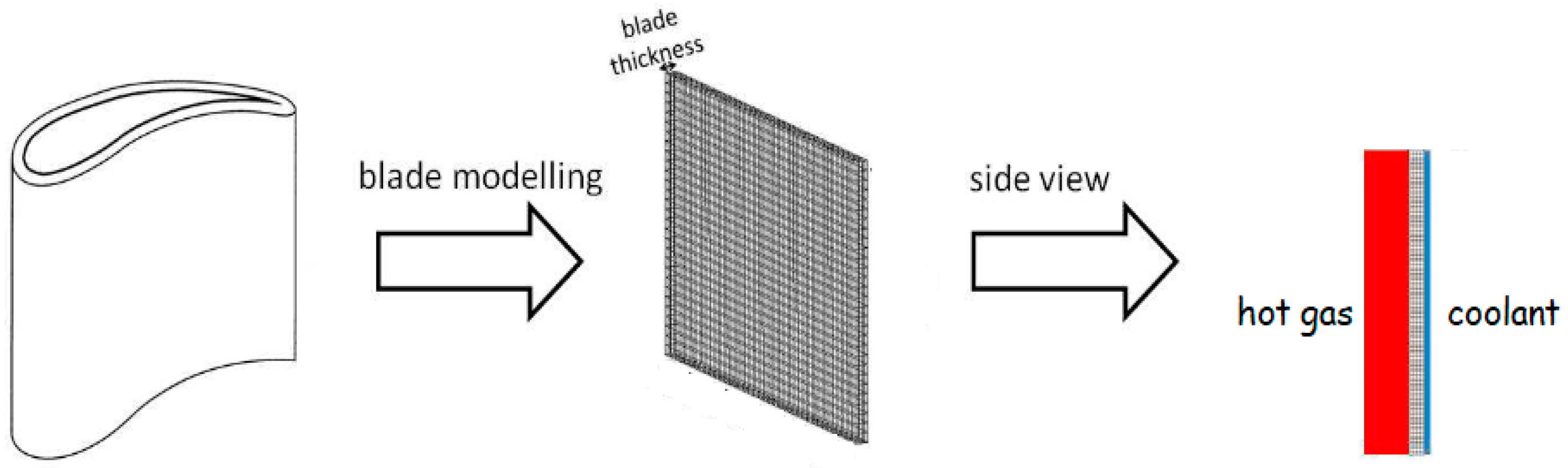
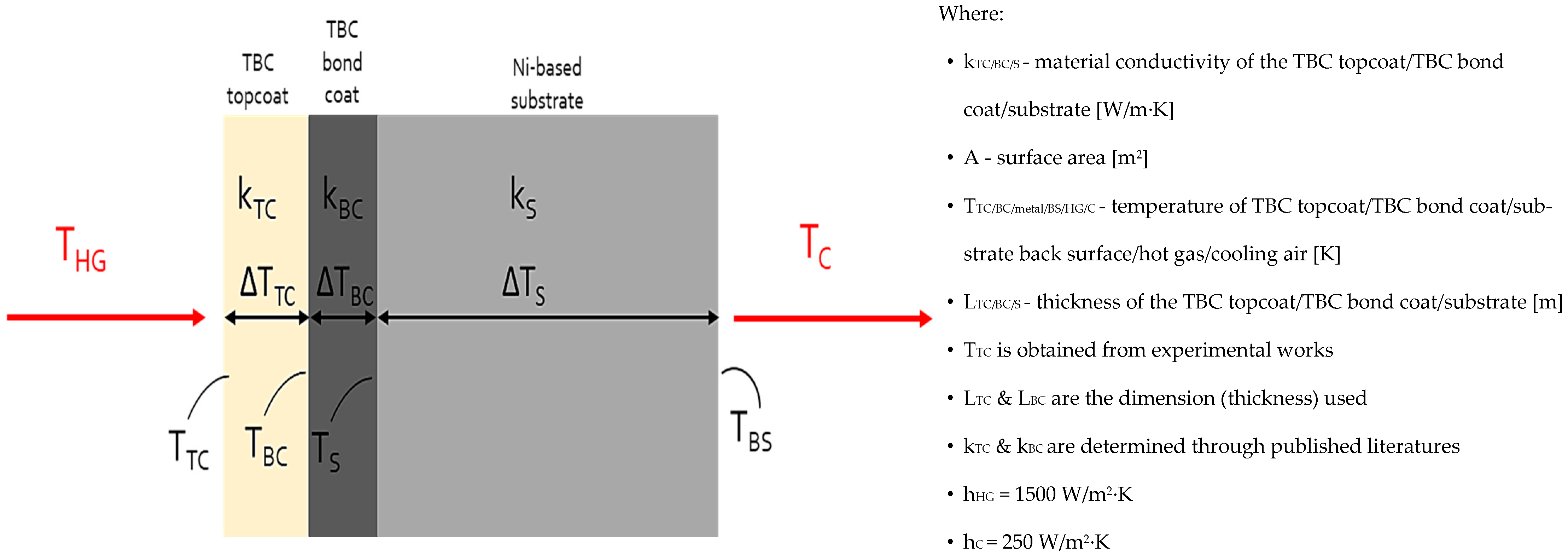
3.1. Thermal Gradient and Two-Dimensional Steady-State Thermal Analysis of Turbine Blades with Hybrid Cooling Systems

3.1.1. Thermal Gradient of the Actual Turbine Blade with the Hybrid Cooling

The thermal gradient was developed using an actual turbine blade model equipped with hybrid cooling protection, including the TBC and internal cooling. Accurate prediction of maximum metal temperature, Tm,max, is essential because it is a critical parameter for assessing the effectiveness of the cooling strategies employed in protecting the turbine blade. Ensuring the simulated and experimental Tm,max values match closely verifies that the model can reliably predict the temperature distribution experienced by the blade during operation. Comparing the simulated and experimental Tm,max values can validate the thermal and cooling models. A close match between these values indicates that the model accurately represents the thermal behavior of the blade under operational conditions. This validation is crucial for optimizing cooling strategies, improving blade material selection, and ultimately enhancing the performance and durability of gas turbines in power plants.
Figure 4 shows the actual and schematic turbine blade model with the hybrid protection of the TBC and the internal cooling used to simulate the actual turbine blade thermal gradient. The blade’s geometric profile was crafted by sketching the cross-sections of the blade at the specified positions (top, 1/4, 1/2, bottom, and hub) using the sketch tools in SolidWorks. Each sketch should accurately represent the blade’s shape and dimensions at that specific location along its length. Each section accounted for specific airfoil coordinates positioned at 100%, 50%, and 0% span. Section curves were generated using the (x, y) plane at various blade spans. The space between these curves represented the blade’s height along the z-axis orientation. Subsequently, the three-dimensional (3D) geometry of the blade profile was constructed by employing the lofted extrude tool. The chord length was 72.67 mm, the trailing edge thickness was 7.4 mm, and the tip thickness was 9.38 mm. Fluid-structure interaction simulation was performed using SolidWorks software (version 2020), delineating three primary domains: solid, fluid, and solid–fluid. The solid domain encompassed conductive heat transfer within the Ni-based superalloy and between adjacent solid regions of the TBC. The fluid domain represented convective heat transfer facilitated by the hot gas and the cooling air. The generated meshes were 2,049,444 fluid cells, 2,444,739 solid cells, and 475,730 fluid cells containing solid. The general properties used are presented in Table 2. The flow conditions used for the conjugate heat transfer (CHT) analysis are given in Table 3.

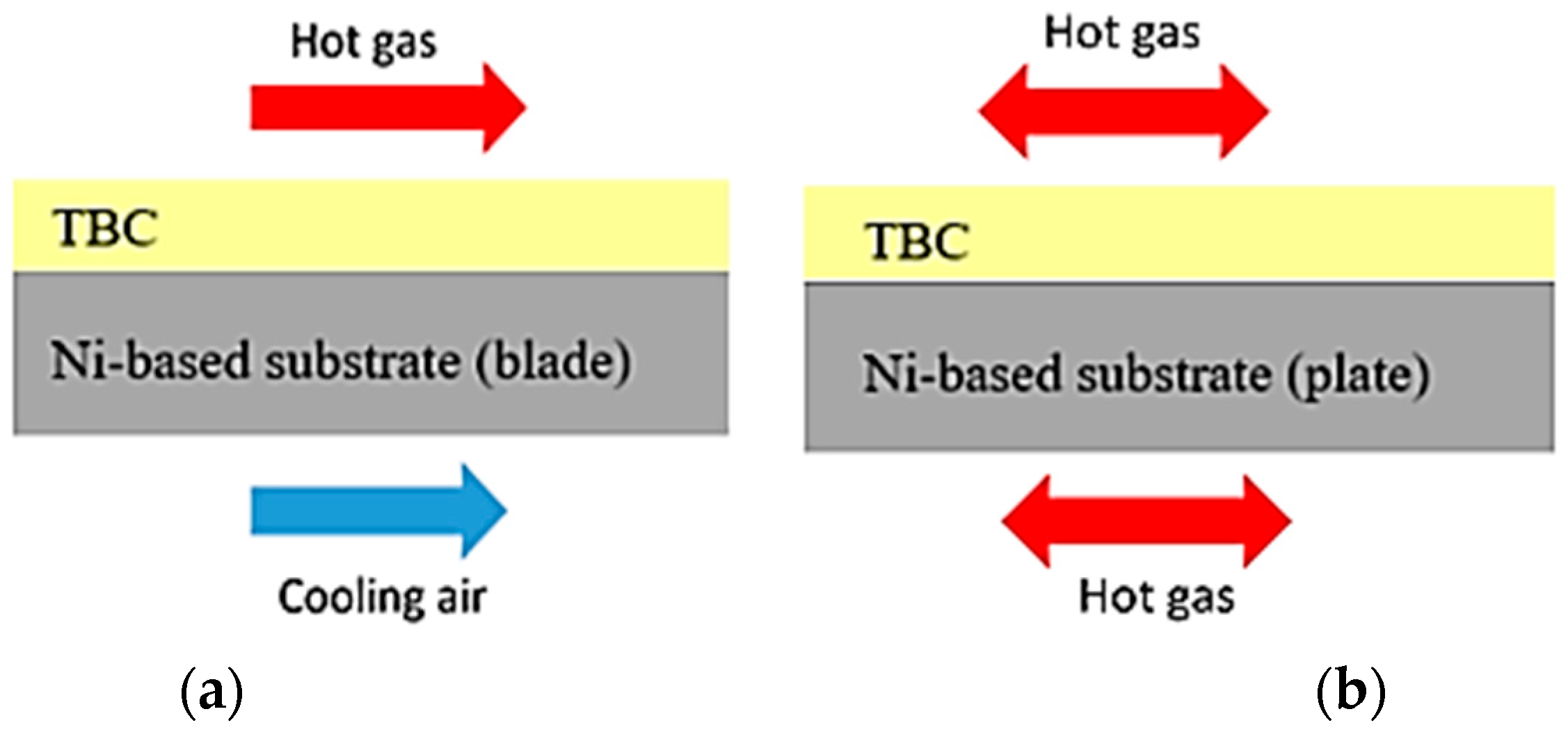
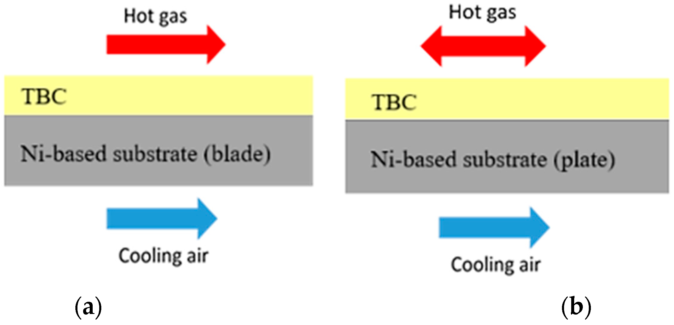
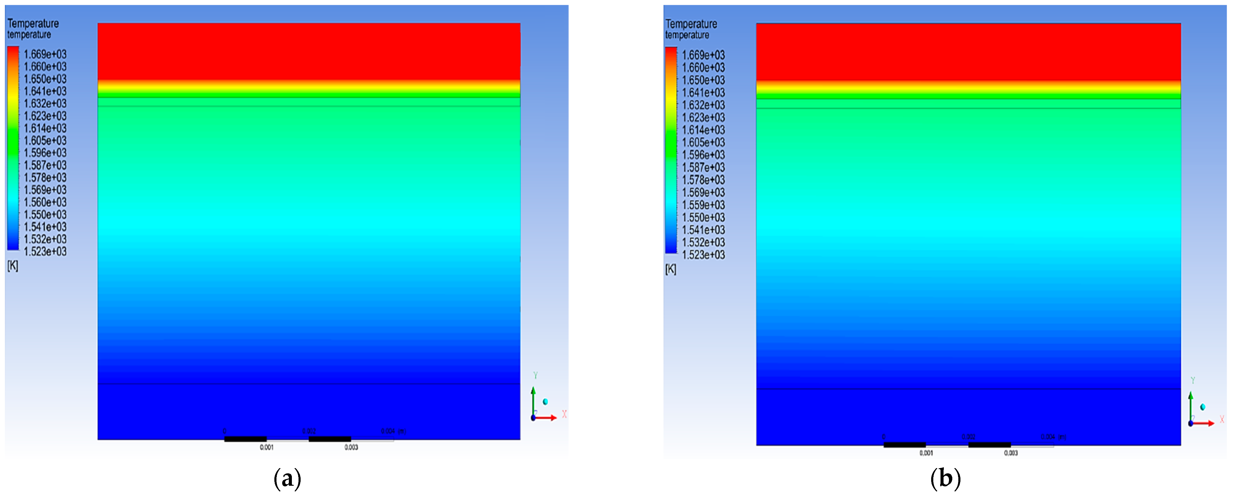
3.1.2. Two-Dimensional Steady-State Thermal Analysis of the Different Hot Gas Conditions

The temperature of a gas turbine blade is influenced by the heat transfers between the hot combustion gases and the coolant used to protect the blade. This interaction creates a temperature profile across the blade that must be carefully managed to ensure the blade’s durability and performance. Software simulations using two-dimensional (2D) modeling were employed to predict and control this temperature profile accurately. Figure 5 illustrates the 2D modeling approach used to simulate the temperature profile of a gas turbine blade. The simulation was designed to replicate the dynamic conditions of a flowing hot gas environment, as experienced in actual gas turbine operations, and the static conditions of an isothermal oxidation test. This simulation aimed to ensure that the conditions within the model accurately reflect the actual thermal exposures at an acceptable confidence level. In dynamic, flowing conditions, the simulation accounted for the continuous movement of hot gases over the blade surface and replicated the high thermal loads and rapid temperature changes during gas turbine operation. In the static condition used for isothermal oxidation tests, the simulation modeled the steady-state exposure of the blade to high temperatures without the influence of flowing gases and provided insight into the blade material’s long-term thermal stability and oxidation resistance. This verification ensured that the simulation’s temperature profiles closely matched those observed in turbine operations and isothermal oxidation tests.
The 2D steady-state thermal model was designed and analyzed using the finite element method through ANSYS Mechanical software (version 22R1). Three different layers of materials were applied in this 2D model. The general dimension of this 2D model was 25 mm × 50 mm, similar to the TBC specimen size used in this study. The cross-section dimension of the model is shown in Figure 6. Meshing for this 2D modeling had 52,315 nodes and 16,800 elements, and the boundary conditions applied are shown in Figure 7. The general properties of the material for each layer are similar to those in Table 2.
The analysis of temperature distribution within TBC layers relies on fundamental principles rooted in thermodynamics and heat transfer. Newton’s law of cooling, represented by Equation (1), governs convective heat transfer, which is crucial for understanding how heat is exchanged between the TBC surface and the surrounding fluid or gas. This law states that the heat transfer rate between a surface and its surrounding fluid is proportional to the temperature difference between the surface and the fluid. Fourier’s law, represented by Equation (2), governs conductive heat transfer within the solid materials of the TBC system. This law states that the heat transfer rate through a material is proportional to the negative temperature gradient and thermal conductivity. These fundamental laws provide the numerical basis for simulating the temperature distribution within TBC layers.
Newton s   law   ( convection ) :   Q = h A T
where Q is the heat transfer rate (W @ J/s), h is the heat transfer coefficient (W/m2.K), A is the surface area (m2), and T is the temperature (K).
Fourier s   law   ( conduction ) :   Q = k A T L = T R
where Q is the heat flux (W), k is the thermal conductivity of layer material (W/m.K), A is the surface area (m2), L is the thickness of material (m), and T is the temperature (K). Boundary conditions such as temperature, convection, and heat flux are applied. The fluid properties and flow conditions are defined using the Fluent module within ANSYS Workbench.

3.2. Experimental Analysis

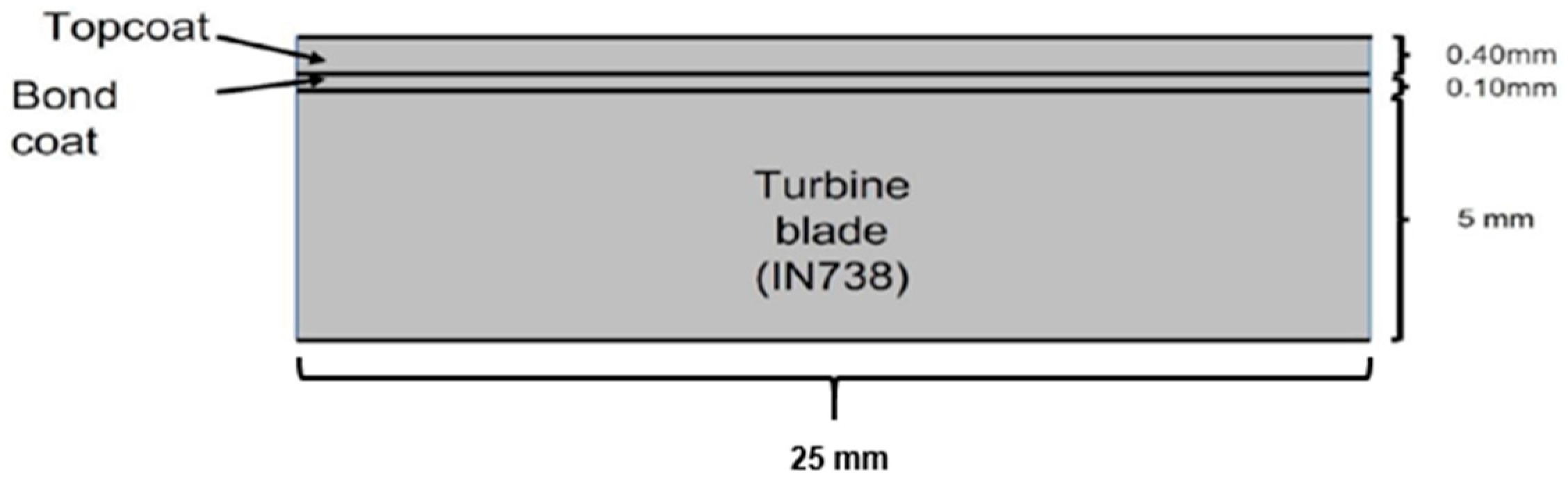
3.2.1. Specimen Preparation

The materials used in the TBC system for this study consisted of commercially available powders for the topcoat and the bond coat. The topcoat was applied using a commercial YSZ powder (Metco 204NS-G, Oerlikon Metco, Wohlen, Switzerland). YSZ is widely used in TBC applications due to its excellent thermal insulation properties and stability at high temperatures [45]. A commercial NiCrAlY powder (Amdry 962 (without Co), Oerlikon Metco, Switzerland) was used for the bond coat. NiCrAlY coatings are commonly used in TBC systems due to the ability to form a protective oxide layer that enhances the adhesion of the topcoat and provides additional oxidation resistance to the underlying substrate. The precise elemental compositions of these powders, which are critical for understanding the performance and interactions within the TBC system, are detailed in Table 4. This elemental composition of starting materials offers insight into the properties and expected behavior under high-temperature conditions.
The air plasma spray (APS) method deposited a dual-layer TBC system using the ABB Automation Technologies AB, IRB 4600 M2004, SE-721 68 Västerås, Sweden. The spray parameter set was selected based on prior experience in coating deposition for gas turbine applications, and the deposition parameters are presented in Table 5. The APS coating was sprayed on the 5 mm Inc738LC plate, and the thickness for the topcoat and bond coat is detailed in Figure 8.

3.2.2. Isothermal Oxidation Test Using Modified Furnace

The isothermal oxidation test rig was equipped with four thermocouples to monitor and control the thermal environment accurately during testing. The first thermocouple was located at the cooling air inlet to ensure the cooling air temperature was precisely 400 °C before reaching the TBC specimen. The second thermocouple was positioned just before the placement of the TBC specimen to confirm that the cooling air maintained its temperature at 400 °C upon arrival. The third thermocouple was placed on the surface of the TBC specimen to verify that the exposed temperature was consistently 1400 °C to simulate the high-temperature conditions of advanced gas turbine operations. The fourth thermocouple was located at the back surface of the TBC specimen to help calculate the temperature of the Ni-based substrate and provide insight into the effectiveness of the thermal gradient and cooling mechanism. This thermocouple monitored the cooling air outlet temperature, which should be higher than the inlet temperature, indicating effective heat transfer from the TBC specimen. The isothermal oxidation test was conducted for 100 h, and the TBC system was exposed to prolonged high temperatures to evaluate its thermal stability and degradation behavior. The 100 h testing was selected to meet the requirement for validation or durability tests typically performed by/for the gas turbine original equipment manufacturer, such as the Electric Power Research Institute and Mitsubishi Hitachi Power Systems [46,47,48]. Table 6 details the parameters used during the isothermal oxidation test to ensure a consistent, reproducible testing environment. This setup enabled precise monitoring and control of the temperature conditions experienced by the TBC system and provided valuable data on its performance under simulated operational conditions.

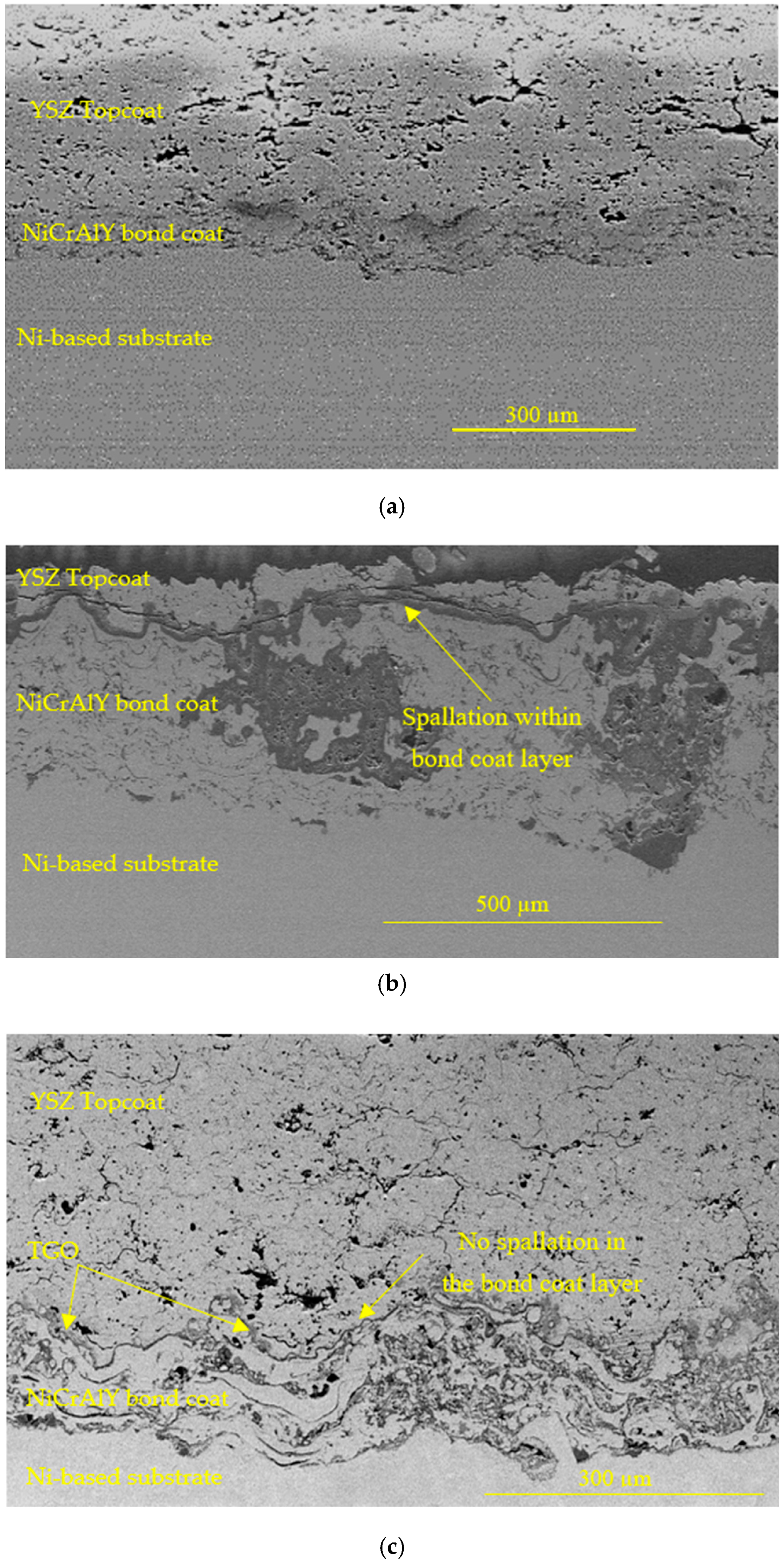
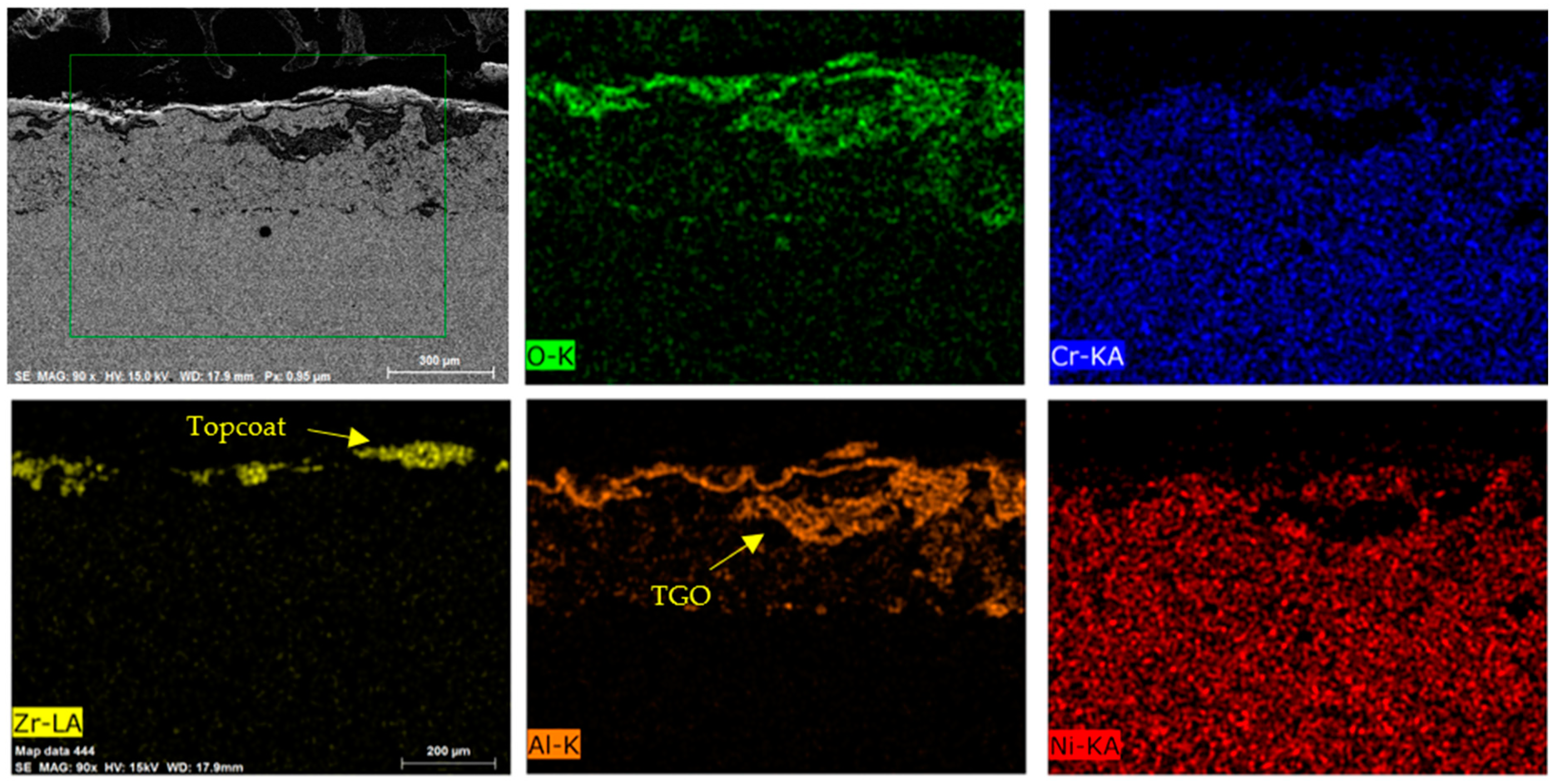
3.2.3. Specimen Characterization

The microstructural analysis of the specimens was captured by scanning electron microscopy (SEM, SU8020, Hitachi High-Technologies Corporation, Tokyo, Japan) equipped with an energy-dispersive X-ray spectrometer (EDS, Xflash Detector 6160, Bruker Nano GmbH, Berlin, Germany). Secondary electron imaging images using 15.0 kV with 150X magnifications were used for microstructure analysis. As recommended by many works [7,13,18,49], SEM and EDS analyses provide detailed insights into the changes in the coating’s morphology and chemical composition, which are crucial for evaluating its performance in high-temperature applications.

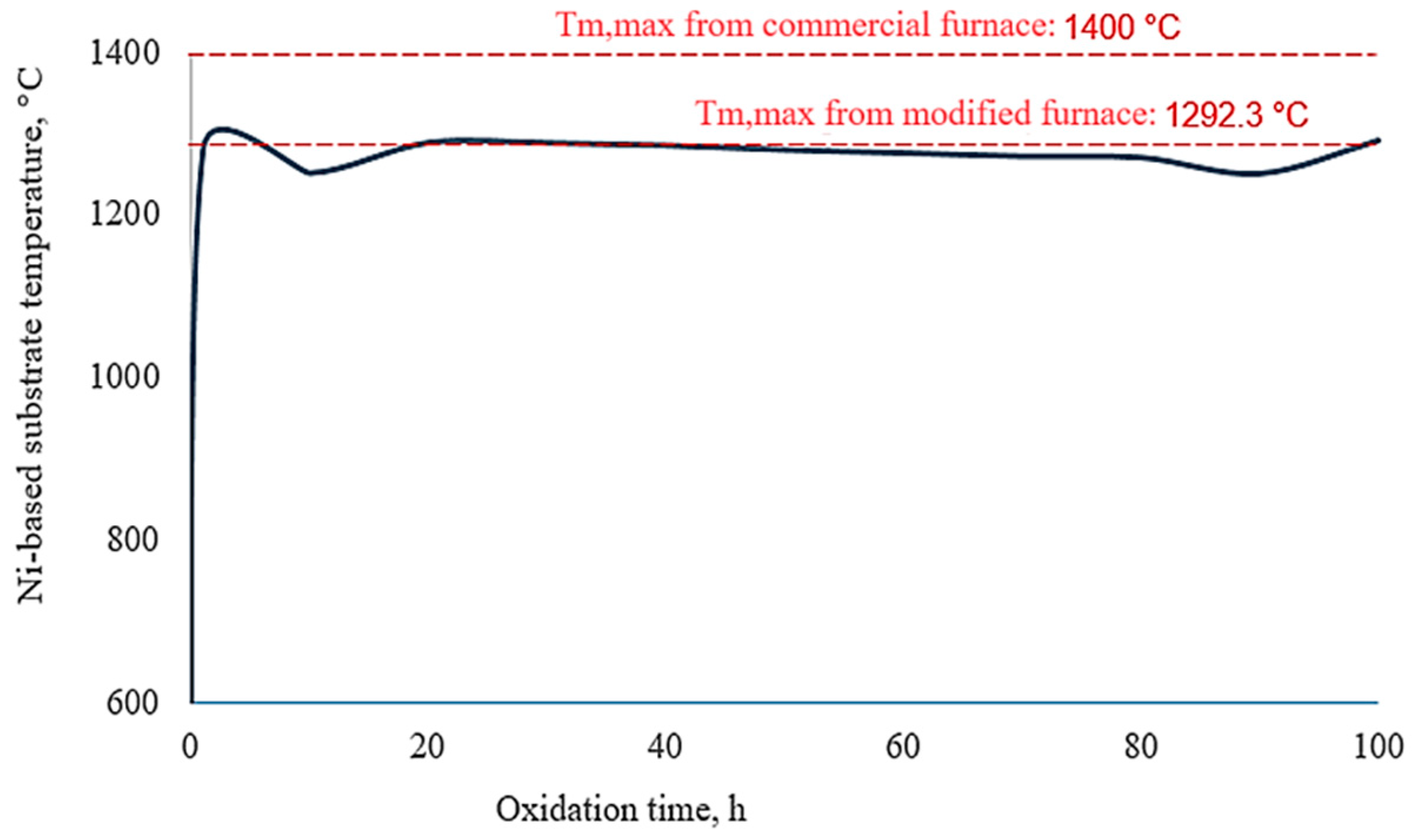
3.2.4. Determination of the Ni-Based Substrate Temperature

The principle of heat flux at steady-state is a fundamental concept in thermal analysis. The principle states that the rate of energy transfer or heat flux into a system is equal to the rate of energy transfer or heat flux out of the system. This balance results in a constant temperature distribution within the system, assuming no accumulation of heat within the system itself [50]. This principle is used in many engineering applications, including the design and analysis of heat exchangers, insulated walls, and other thermal management systems, because it ensures temperature gradients and thermal stresses are effectively managed to prevent material degradation or failure [2]. This principle is applied to the TBC system to maintain a stable thermal environment for the coated specimen. Figure 9 illustrates how this heat flux principle was applied to a TBC-coated specimen exposed to hot gas and cooling air temperatures. On one side, the TBC surface was subjected to high temperatures, such as the 1400 °C furnace air, whereas on the other side, cooling air at 400 °C was directed toward the back surface of the specimen. At a steady state, the heat entering the system from the hot gas must equal the heat leaving the system through the cooling air. This equilibrium ensured that the temperature distribution across the TBC remained constant, prevented overheating of the Ni-based substrate, and maintained the integrity of the TBC.
The principle of heat flux at steady-state (Equation (3)),
h H G T H G T T C = k T C L T C T T C T B C
Rearranging Equation (3) to obtain the bond coat temperature, TBC (Equation (4)). TBC is calculated from the heat flux from the hot gas side,
T B C = T T C h H G L T C k T C T H G T T C
Tm is calculated using the heat flux from the coolant (cooling air) side (Equation (5)):
k T C L T C T T C T B C = k B C L B C T B C T m
Rearranging Equation (5) to obtain the metal (Ni-based) temperature (Equation (6)),
T m = T B C k T C L B C k B C L T C T T C T B C

4. Results and Discussion

4.1. Effects of the Hot Gas Flows

The 2D steady-state thermal analysis results predicted the hot gas effect during the isothermal oxidation test. Figure 10 illustrates the substrate’s temperature gradient under flowing and static hot gas conditions and comprehensively compares how these conditions affect the TBC system. This illustration is supplemented by detailed results in Table 7, which quantify the temperature variations and validate the comparative analysis. The data reveal only minor deviations between the temperature gradients observed under flowing and static hot gas conditions. This small difference confirms the initial assumption that the hot gas flow does not substantially affect the thermal gradient within the TBC system. The negligible influence of gas flow on the temperature gradient suggests that the convective effects of the gas velocity are minimal compared with the dominant influence of the high temperature itself. This finding is substantial because it indicates that at extremely high temperatures, the velocity of the hot gas has a negligible effect on the thermal gradient. This verification has practical implications for designing and analyzing TBC systems in high-temperature applications such as gas turbines. Simplifying assumptions about the negligible influence of gas flow velocity on thermal gradients is valid, especially in cases that focus more on the material properties and temperature effects when optimizing TBC performance. This approach can streamline computational models and experimental setups and lead to more efficient and accurate evaluations of TBC systems.

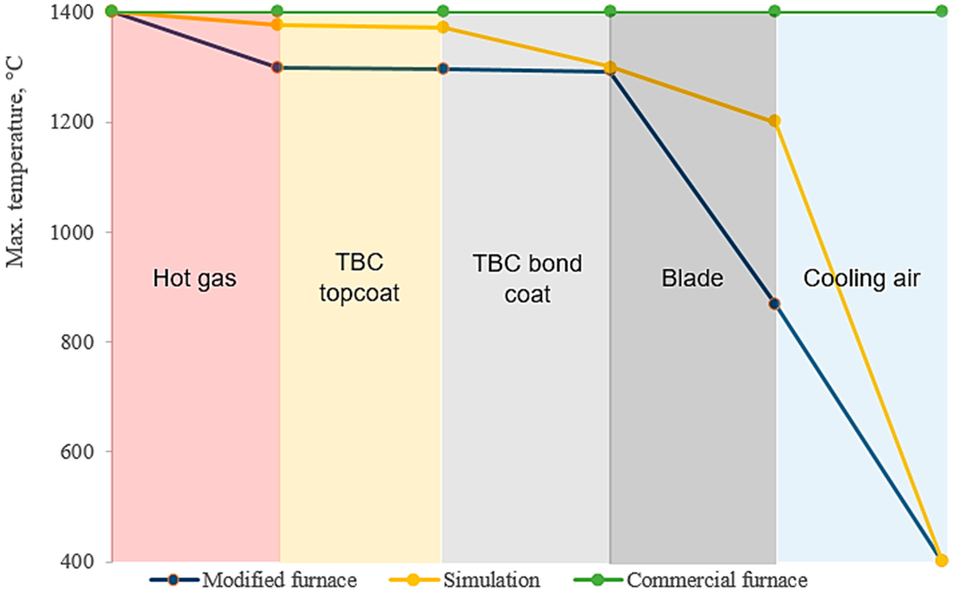
4.2. Reliability of the Developed Thermal Gradient

In this study, the Tm,max is a crucial parameter that serves as the primary metric for evaluating the effectiveness of the turbine blade cooling system. Tm,max is vital in assessing the thermal protection provided by the TBC and internal cooling mechanisms. The ability of this hybrid cooling system to maintain Tm,max within safe limits indicates the system’s overall performance and reliability. Therefore, accurately predicting and validating Tm,max is essential for confirming the success of the developed protection system. From the simulation works, Tm,max generated was 1300 °C. The isothermal oxidation test was conducted using a modified furnace, and a Tm,max of 1292.3 °C was obtained. This result is considerable because it demonstrates that the presence of cooling air substantially affects reducing the blade’s metal surface temperature, as indicated by the thermal gradient analysis. Moreover, it validates the findings from the experimental work performed with the modified furnace. Consequently, accurately replicating this condition through isothermal oxidation tests is crucial, which cannot be achieved using a standard commercial furnace. This comparative study between the obtained Tm,max through the modified furnace and from the actual turbine blade model highlights the effectiveness of the TBC system’s cooling capabilities under high-temperature conditions.
Figure 11 illustrates the temperature gradient within the TBC system and provides a comparative analysis between the outcomes of the simulation and the experimental analyses. Table 8 shows the predicted temperature at each layer for each TBC system, where the temperatures from the experimental works are calculated using Equations (4) and (6). The agreement between the predicted and experimental temperature profiles demonstrates the accuracy of the simulation in replicating the actual gas turbine thermal conditions and confirms that the thermal gradient developed in the modified furnace, when applied to the actual turbine blade model, effectively mimics the operational environment. This validation ensures that the cooling strategies can be optimized based on reliable data to enhance the overall performance and durability of the turbine blades. The validated model helps identify potential hotspots, optimize cooling air distribution, and select materials with the best thermal properties to withstand the demanding conditions within gas turbines. Furthermore, simulation and experimental work using the modified furnace demonstrates that TBC-coated specimens require proper test-rig facilities to replicate the thermal gradient accurately. Simplifying the thermal gradient, as performed in a commercial furnace, is insufficient. In the modified furnace, precise control over temperature distribution and gradient is possible, closely mimicking the real-world conditions that TBC would encounter in the gas turbine operation. This level of control enables a more accurate assessment of the TBC’s behavior under realistic thermal loading conditions.
The commercial furnace offers a simplified approach to creating thermal gradients and is unable to reproduce the complex temperature profiles in actual applications. This simplification can lead to inaccurate or misleading results because the failure modes observed in a commercial furnace may not correspond to those in real operational environments. Research has shown that accurately reproducing the thermal gradient is critical for understanding the performance and degradation mechanisms of TBCs. The shown thermal gradient for TBC in the commercial furnace explains the TBC failure. Furthermore, Karaoglanli et al. [26] emphasized the importance of replicating operational thermal gradients to obtain meaningful results from durability tests. Hu et al. [51] reported that discrepancies in thermal gradient replication can substantially affect the observed lifespan and failure modes of TBCs.
The percentage error between the experimentally obtained Tm,max, and the simulated prediction was calculated. This error is showcased in Figure 12, where the percentage error represents the difference between the actual value from the experimental isothermal oxidation test and the value predicted by the simulation. The results reveal minor discrepancies between the experimental and simulated Tm,max using the modified furnace facilities with an average error of 1.8%. In comparison, the error from the commercial furnace was an average of 8.8%. The slight differences from the modified furnace testing indicate a close alignment between the experimental data and the simulated predictions. Such minor validation errors suggest that the modified furnace’s thermal gradient is highly effective in replicating the thermal behavior of the TBC system under operational conditions. This close correlation between the experimental and simulated values also highlights the reliability of the modified furnace in creating realistic thermal conditions, which is essential for accurate gas turbine high-temperature exposures. The high accuracy in replicating the thermal gradient ensures that the experimental setup can effectively imitate the operational environment, leading to more precise TBC performance and durability assessments [52].
Figure 13 shows the microstructure of the TBC specimen as-sprayed and after the isothermal oxidation test using the commercial furnace. Figure 13b shows that the topcoat spalled and the bond coat exhibits severe internal oxidation. This morphology is expected. Tao et al. [53] reported that the conventional YSZ undergoes 3–5% coating volume expansion that results in spallation when exposed to temperatures beyond 1250 °C. Musalek et al. [54] reported that the NiCrAlY bond coat suffered from severe internal oxidation within the bond coat at temperatures beyond 1400 °C. Spallation of the TBC topcoat accelerates the exhibition of the internal oxidation of the bond coat because there is no thermal insulation. TBC failure after both exposure times is expected because YSZ could not withstand operating temperatures beyond 1170 °C. Figure 13c indicates no coating delamination or cracks at the topcoat/bond coat and bond coat/substrate interfaces after 100 h of isothermal oxidation using the modified furnace. The exhibited microstructure highlights a remarkable improvement due to the enhanced isothermal oxidation test rig, which simulates advanced gas turbine conditions more accurately by maintaining a more uniform temperature gradient across the TBC. The absence of coating delamination or cracks can be attributed to the effectiveness of the hybrid cooling approach. By maintaining a controlled thermal gradient and reducing the temperature of the metal substrate, the cooling system minimized thermal degradation and fast TGO growth, which are the primary causes of coating failure. This controlled environment helped preserve the integrity of the YSZ TBC and its underlying layers and ensured better structural stability over prolonged exposure to high temperatures. The cooling air system directed 400 °C air to the back surface of the TBC specimen while exposing the front to 1400 °C furnace air. This setup created a more realistic thermal gradient, similar to the actual operational conditions of gas turbines. Hu et al. [41] reported that temperature distribution is one of the two main parameters used to study the TBC in the actual operation of gas turbines. Therefore, improving the TBC specimen’s thermal gradient during experimental works reduces misinterpretation and prediction of the TBC and blade metal behavior under actual advanced gas turbine applications.
Figure 14 presents the Tm,max recorded throughout the 100 h isothermal oxidation test using the modified furnace and compares it with the predicted temperature from Equations (4) and (6). The test reveals that the average surface temperature of the Ni-based substrate was 1292.3 °C. This result reveals the effectiveness of the modified furnace, which is equipped with a cooling air system, in improving the thermal gradient of the TBC system under high-temperature conditions of 1400 °C. Implementing the cooling air system in the modified furnace is crucial in improving the thermal gradient and reducing metal temperature. This reduction in temperature is substantial because it helps reduce potential degradation mechanisms, such as oxidation and spallation, which can compromise the integrity of the TBC and the underlying substrate. The satisfactory performance of the conventional YSZ TBC system under these stringent conditions, facilitated by the modified furnace, suggests this experimental setup is highly effective for simulating and studying the behavior of TBC systems in high-temperature environments typical of advanced gas turbines. The controlled thermal gradient provided by the cooling air system facilitates a more accurate replication of real-world operational conditions; thus, it is a valuable tool for evaluating the material behavior and performance of TBCs. Consequently, the modified furnace is recommended for further evaluations and studies of TBC systems intended for advanced gas turbine applications. Its ability to simulate high-temperature exposure while maintaining manageable substrate temperatures provides a robust platform for assessing TBC materials’ durability, performance, and failure mechanisms under realistic service conditions. This setup ensures that TBC systems can be thoroughly tested and optimized for improved performance and longevity in high-temperature turbine operations.
However, the obtained Tm,max for this conventional TBC system still exceeded the allowable operating temperature for Ni-based superalloys. Despite the improvements in thermal management achieved with the current TBC system, the Ni-based substrate was still exposed to temperatures that could compromise its structural integrity and performance. Given this challenge, exploring alternative coating materials that can provide enhanced thermal protection and effectively lower the Tm,max to within safe operating limits for Ni-based superalloys is crucial. Advanced coating materials, such as those with higher thermal resistance or improved thermal conductivity properties, could benefit considerably. For instance, materials such as rare-earth zirconates or multilayered TBC systems might be more effective in reducing the heat transfer to the substrate, thereby maintaining lower temperatures under high-temperature operating conditions. The recommendation is that coatings with higher resistance to oxidation and spallation, more thermally stable at high temperatures beyond the YSZ material, and can form more stable TGO layers be studied, which could also contribute to achieving lower Tm,max. Furthermore, integrating advanced cooling techniques, such as more efficient internal cooling channels or active cooling systems, in conjunction with new coating materials, could provide a synergistic effect and substantially improve the overall thermal management of the TBC system.
Numerous research reviews have discussed several alternatives to improve the conventional TBC performance. Iqbal and Moskal [55] reported that the characteristics of TBC, including advanced materials such as gadolinium zirconate, lanthanum zirconate, and ceria-stabilized zirconia; structures such as monolayer, double, triple, and multilayer ceramic coatings; and phases such as cubic and tetragonal impart specific effects that enhance their reliability in various high-temperature applications, including gas turbines. Mondal et al. [56] reviewed potential improvements through alternative manufacturing processes such as laser chemical vapor deposition and additive manufacturing techniques. Consequently, various options are available to enhance the conventional TBC system, and these are recommended to be assessed using the modified furnace to simulate advanced gas turbine temperature exposures.

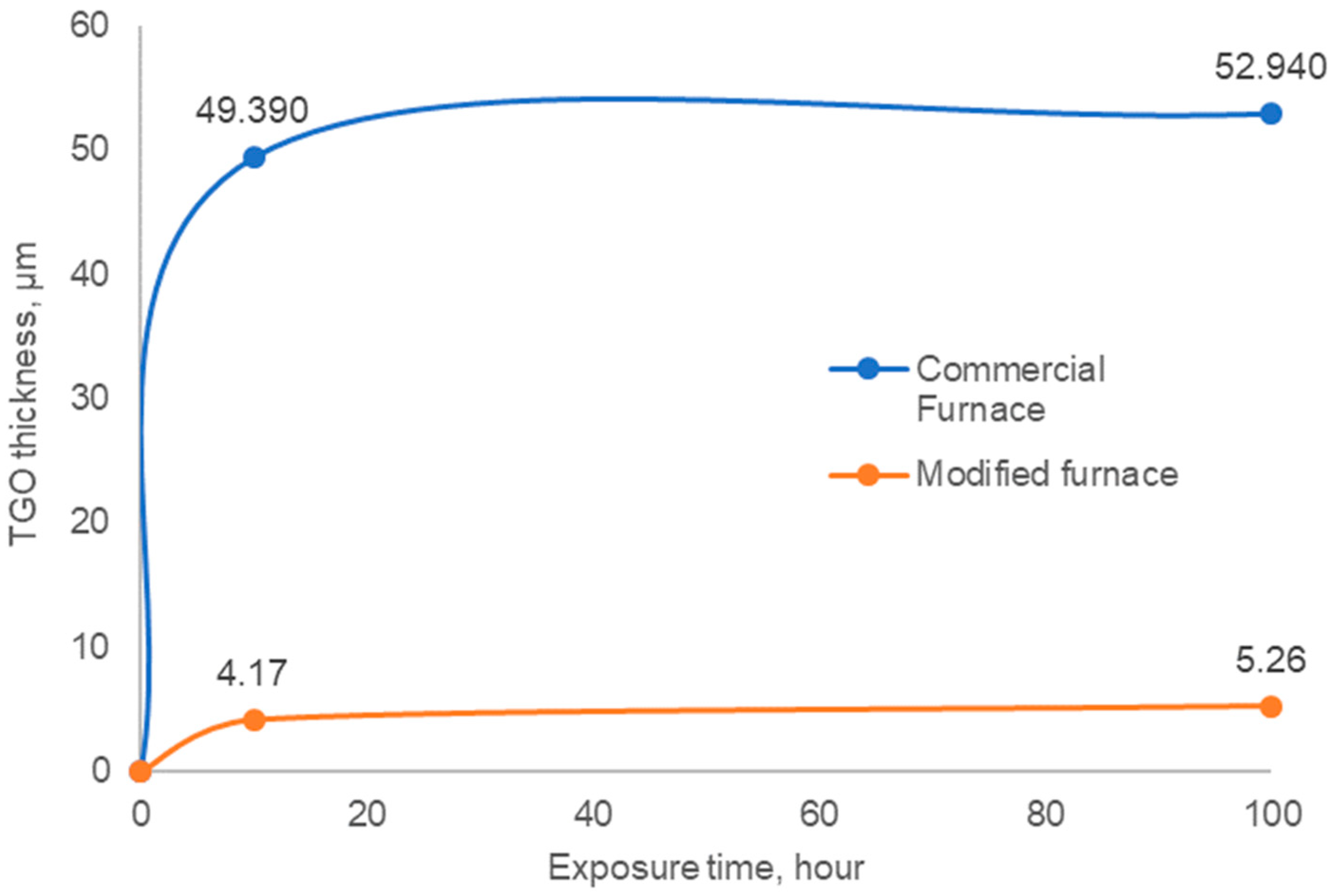
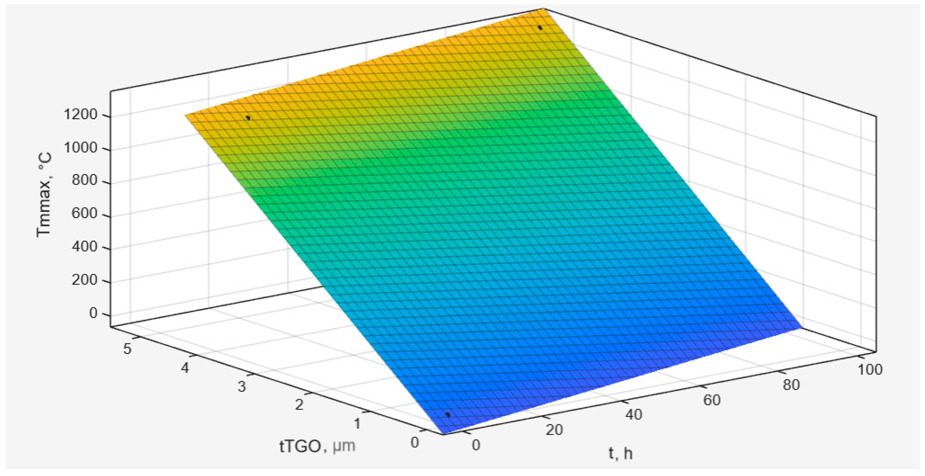
4.3. Temperature Model for Isothermal Oxidation

The commercial furnace setup, which lacked this cooling mechanism, subjected the TBC to a uniform high temperature without a thermal gradient, leading to an aggressive environment. This outcome is shown by the elemental composition from the EDS results in Table 9, which reveals a substantial Cr-content reduction in the TBC topcoat after the isothermal oxidation test using the commercial furnace. The high Cr-diffusion to the bond coat in the commercial furnace led to more considerable topcoat degradation. The interdiffusion of Cr can weaken the bond coat and further accelerate the degradation of the entire TBC system. This phenomenon has been discussed by many researchers, such as Wang et al. [57] and Liu and Hu [58], who conducted the test at 1100 °C, and Bao et al. [59], who reviewed the interdiffusion effect of the single crystal superalloy. Thus, the high Cr-diffusion observed clearly indicates the detrimental effect on the durability and performance of the coating endured by the TBC that is not equipped with a cooling system (which uses the commercial furnace).
The diffusion of Cr is also likely to result in an increased content of mixed oxides at the bond coat interface. These mixed oxides can considerably deteriorate the protective properties of the coating over time. Cr is essential for forming a stable, protective oxide layer on the bond coat, which acts as a barrier against further oxidation and thermal degradation. As Cr diffuses away from the topcoat into the bond coat, the topcoat becomes depleted of this critical element, and its protective oxide layer is weakened. Archana et al. [60] reported that the diffusion of Cr is more rapid compared with other alloying elements; therefore, it actively forms chromium oxide (mixed oxide) on top of the protective layer (alumina). The higher Cr diffusion into the bond coat facilitates the formation of detrimental mixed oxides, which can compromise the structural integrity and performance of the TBC system. Mixed oxides are often less stable and more prone to spallation, reducing the effectiveness of the TBC in insulating the underlying substrate from high temperatures.
By contrast, this phenomenon is less pronounced in TBCs subjected to a modified furnace environment. The controlled thermal gradient in a modified furnace helps maintain the original composition of the TBC and the bond coat. By carefully managing the temperature distribution, the modified furnace minimizes the extent of Cr diffusion and the subsequent formation of mixed oxides. Savitha et al. [61] reported that a high thermal gradient in the coating system induces substantial thermal stress and makes it more susceptible to cracking and spallation. Consequently, they recommended improving the thermal gradient, and their findings demonstrated that this approach successfully reduces thermal stress and enhances coating adhesion. Additionally, Mehtani et al. [62] observed that reducing ionic diffusion, such as Cr, decreases the formation of voids at the topcoat/bond coat interface and improves the mechanical integrity of the TBC system. Cui et al. [63] also found that lowering the ceramic coating temperature minimizes interdiffusion, thus improving the oxidation resistance of the coating. This controlled environment ensures that the protective properties of the TBC are preserved for a longer duration, enhancing the durability and performance of the coating system under high-temperature conditions.
The evaluation of TBC systems using different furnace environments reveals remarkable performance and degradation characteristic differences. Figure 15 presents the element mapping of the TBC system after an isothermal oxidation test for 100 h using a commercial furnace without cooling. The results from this setup indicate no distinct demarcation line at the interface between the bond coat and the Ni-based substrate. This absence of a clear boundary is a crucial finding and highlights the limitations of the commercial furnace in accurately replicating the hybrid protection system used in advanced gas turbine operations. In this environment, the bond coat and the underlying metal substrate undergo severe oxidation, leading to substantial degradation. This outcome is evidenced by clear bond coat interspallation, where the bond coat is detached from the substrate, compromising the protective capabilities of the TBC system. Additionally, the element mapping shows distinctive evidence of the formation of TGO, which is essential for evaluating the performance and longevity of the TBC system. TGO thickness measurement using ImageJ is 52.94 µm. This extremely high TGO thickness is attributed to the TBC failure. Hu et al. [64], through their finite element analysis, found that the limit of the TGO thickness for the APS YSZ TBC system is in the range of 8–10 µm only. The extremely high-temperature exposures at 1400 °C definitely accelerated the growth of TGO.
Numerous experiments have consistently shown that high-temperature exposures lead to substantial TGO growth, which causes the failure of TBC. For example, Shi et al. [11] found that at a TGO thickness of 6.0 µm, the APS YSZ spalls when exposed to a temperature of 1000 °C. This outcome indicates that even moderate TGO growth can critically undermine the coating’s integrity at high temperatures. Similarly, Essa et al. [20] reported that topcoat delamination occurs at a TGO thickness of 11.28 µm under 1100 °C exposures. This thicker TGO layer demonstrates how prolonged high-temperature conditions can exacerbate TGO formation, thus creating a weak path between the topcoat and the bond coat and ultimately causing failure. Furthermore, Mahade et al. [12] conducted thermal cyclic tests at an even higher temperature of 1400 °C, with cooling air set at 1050 °C. They found that the TBC fails when the TGO thickness is less than 2 µm. This finding highlights that even thin TGOs can lead to failure under extreme temperature fluctuations and thermal cycling and emphasizes the fragility of the TBC system in such harsh conditions. These studies collectively stress the critical influence of TGO growth on the durability and performance of TBC systems. As the TGO layer thickens, it induces stress and strain within the coating structure, leading to spallation or delamination.
The TBC system tested using a modified furnace with cooling demonstrates markedly different, more favorable results, as illustrated in Figure 16. The element mapping for this setup clearly reveals the formation of TGO. The presence of TGO can be seen not only at the interface of the topcoat/bond coat but also within the bond coat region. This result indicates the progressive growth of TGO during the isothermal oxidation. The measured TGO thickness is 5.26 µm. The rapid growth of the TGO might be due to the high temperature exposed to this conventional YSZ TBC system. As discussed previously, Mahade et al. [65] tested the conventional APS TBC system, assisted with the cooling system but in cyclic condition, and found TBC spallation. The evaluation of this conventional TBC system in static and cyclic revealed that the YSZ material might not be suitable for advanced gas turbine applications. The allowable operating temperature for the Ni-based superalloy is 1250 °C [66,67]. Using YSZ is insufficient to reduce the metal substrate to lower than the allowable operating temperature. Looking at this severe TGO growth, the temperature of the Ni-based superalloy is expected to reach or exceed 1250 °C. However, the cooling assistance in this hybrid cooling protection system improves the thermal gradient and delays the detrimental effect of spallation.
The controlled thermal gradient provided by the modified furnace played a crucial role in this process. By directing cooling air to the back surface of the TBC-coated specimen, the modified furnace ensured that only the TBC surface was exposed to the high temperature of 1400 °C while the substrate temperature was kept substantially lower. Excessive Cr interdiffusion led to the formation of detrimental mixed oxides, which can impair the mechanical integrity and performance of the TBC system. However, Table 8 shows that the Cr interdiffusion was still lower than when using the commercial furnace. The reduced Cr interdiffusion in the modified furnace setup is expected to preserve the bond coat’s composition and ensure its effectiveness in forming a protective oxide layer.
A preliminary metal temperature model was created to facilitate the management of isothermal oxidation processes in TBC systems subjected to high-temperature conditions. This model aimed to predict and regulate oxidation by offering insights into the thermal gradients within the TBC. This model also enabled researchers to predict the thickness of the TGO for the hybrid system if the turbine blade coated with the TBC cannot be assessed during the gas turbine outage. The measured TGO thickness is given in Figure 17. TGO thickness growth often follows a parabolic pattern due to the nature of the oxidation process [68]. In the initial stages, the growth rate of the oxide layer is rapid because the reactants (typically oxygen and metal atoms such as Ni and Cr) are readily available at the surface. However, as the oxide layer thickens, it acts as a barrier, slows the diffusion of these reactants, and reduces the oxidation rate over time. The parabolic growth law describes this deceleration as the growth rate proportional to the oxide thickness inverse. The thickness increases with time and reflects the decreasing availability of reactants due to the growing barrier effect of the TGO. The Figure shows the TGO thickness growth in lean and peak patterns from the isothermal oxidation test using the modified and commercial furnaces. This pattern refers to the variability in the growth rate of the TGO layer over time and exhibits periods of slower for lean graph (for modified furnace) and faster for peak graph (for commercial furnace) growth. In a lean pattern, the TGO thickness increases slowly, possibly due to lower temperatures from the improved thermal gradient. Conversely, in a peak pattern, the growth rate is accelerated, leading to a more rapid increase in TGO thickness, as expected from the established thermal gradient from the commercial furnace test. This outcome can occur due to higher temperatures, increased reactant availability, or more aggressive environmental conditions, such as higher oxygen partial pressures.
Figure 18 illustrates the relationship between the Tm,max, TGO thickness, and isothermal oxidation duration and combines the commercial and modified furnace results. The developed best-fit line with a 95% confidence level, represented by Equation (7), is the proposed model to predict the thickness of the TGO if a destructive test (to measure the actual TGO thickness) cannot be conducted. The developed model is best for helping gas turbine owners monitor the TGO thickness growth and predict the premature failure of the TBC. The model, generated using MATLAB software (www.mathworks.com/campaigns/products/trials.html, accessed on 29 July 2024), is based on the obtained metal temperature, the measured TGO thickness, and the duration of testing. The model aims to assist further studies in obtaining preliminary Tm,max results for specific tests, primarily dependent on the developed TGO thickness. Including the cooling air system in the modified furnace setup substantially reduces the TGO growth and obtains a lower Tm,max. By providing a controlled thermal environment, the modified furnace enables a more accurate simulation of the operational conditions experienced by gas turbine components and enhances the reliability of the TBC system.
f x , y = 3.6914 x + 315.8068 y
where f(x,y) represents Tm,max in °C, x represents the test duration in hours, and y represents the TGO thickness in µm.
However, while the developed thermal gradient model offers a valuable tool for predicting TGO thickness, further refinement, and validation of the model are recommended to ensure its reliability across a broad range of conditions. Additional experimental data and extended testing are necessary to improve the model’s accuracy and robustness and make it a more dependable resource for hybrid cooling protection system study.

5. Conclusions

The isothermal oxidation test initially conducted using a commercial furnace severely damaged the TBC and the Ni-based substrate. Hence, modifications were made to the furnace, including the installation of a cooling air system. This system enabled the furnace to simulate operational temperatures of 1400 °C for the TBC surface while directing 400 °C cooling air to the back surface and achieving an average Ni-based surface temperature of 1292.3 °C. The modified furnace demonstrated satisfactory performance, reduced metal temperatures, and enhanced TBC durability under high-temperature conditions. Consequently, this modified furnace setup is recommended for evaluating TBC materials’ behavior and performance in advanced gas turbine applications.

Author Contributions

Conceptualization, S.M.Y. and A.M.; methodology, S.M.Y. and S.M.; software, N.M.A.; validation, A.M. and M.S.; writing—original draft preparation, S.M.Y.; writing—review and editing, S.M.Y. and A.M.; supervision, A.M. and M.S.; project administration, S.M.Y.; funding acquisition, S.M.Y. All authors have read and agreed to the published version of the manuscript.

Funding

This research was funded by TNB RESEARCH SDN. BHD.

Institutional Review Board Statement

Not applicable.

Data Availability Statement

The original contributions presented in the study are included in the article; further inquiries can be directed to the corresponding author.

Acknowledgments

We wish to express our sincere appreciation to the numerous individuals and organizations, especially those whose contributions and support have been instrumental in completing and publishing this research. First and foremost, we extend our heartfelt gratitude to our dedicated research team, whose tireless efforts and expertise significantly enriched the research process. This work would not have been possible without the financial support provided by TNB Research Sdn. Bhd. and Department of Mechanical Engineering, College of Engineering of Universiti Tenaga Nasional, whose resources and expertise enhanced the scope.

Conflicts of Interest

The authors declare no conflicts of interest. The funders had no role in the design of the study, in the collection, analyses, or interpretation of data, in the writing of the manuscript, or in the decision to publish the results.

References

  1. Olumayegun, O.; Wang, M.; Kelsall, G. Closed-cycle gas turbine for power generation: A state-of-the-art review. Fuel 2016, 180, 694–717. [Google Scholar] [CrossRef]
  2. Meng, Z.; Liu, Y.; Li, X.; He, X. The performance evaluation for thermal protection of turbine vane with film cooling and thermal barrier coating. Appl. Therm. Eng. 2022, 210, 118405. [Google Scholar] [CrossRef]
  3. Chowdhury, T.S.; Mohsin, F.T.; Tonni, M.M.; Mita, M.N.H.; Ehsan, M.M. A critical review on gas turbine cooling performance and failure analysis of turbine blades. Int. J. Thermofluids 2023, 18, 100329. [Google Scholar] [CrossRef]
  4. Wang, W.; Yan, Y.; Zhou, Y.; Cui, J. Review of advanced effusive cooling for gas turbine blades. Energies 2022, 15, 8568. [Google Scholar] [CrossRef]
  5. Vo, D.T.; Mai, T.D.; Kim, B.; Ryu, J. Numerical study on the influence of coolant temperature, pressure, and thermal barrier coating thickness on heat transfer in high-pressure blades. Int. J. Heat Mass Transf. 2022, 189, 122715. [Google Scholar] [CrossRef]
  6. Mohd Yunus, S.; Mahalingam, S.; Manap, A.; Mohd Afandi, N.; Satgunam, M. Test-rig simulation on hybrid thermal barrier coating assisted with cooling air system for advanced gas turbine under prolonged exposures—A review. Coatings 2021, 11, 560. [Google Scholar] [CrossRef]
  7. Doleker, K.M.; Ozgurluk, Y.; Ahlatci, H.; Karaoglanli, A.C. Evaluation of oxidation and thermal cyclic behavior of YSZ, Gd2Zr2O7 and YSZ/Gd2Zr2O7 TBCs. Surf. Coat. Technol. 2019, 371, 262–275. [Google Scholar] [CrossRef]
  8. Moon, S.W.; Kwon, H.M.; Kim, T.S.; Sohn, J.L. A novel coolant cooling method for enhancing the performance of the gas turbine combined cycle. Energy 2018, 160, 625–634. [Google Scholar] [CrossRef]
  9. Uysal, S.C.; Liese, E.; Nix, A.C.; Black, J. A thermodynamic model to quantify the impact of cooling improvements on gas turbine efficiency. J. Turbomach. 2018, 140, 031007. [Google Scholar] [CrossRef]
  10. Karaoglanli, A.C.; Doleker, K.M.; Ozgurluk, Y. Interface failure behavior of yttria stabilized zirconia (YSZ), La2Zr2O7, Gd2Zr2O7, YSZ/La2Zr2O7 and YSZ/Gd2Zr2O7 thermal barrier coatings (TBCs) in thermal cyclic exposure. Mater. Charact. 2020, 159, 110072. [Google Scholar] [CrossRef]
  11. Shi, J.; Zhang, T.; Sun, B.; Wang, B.; Zhang, X.; Song, L. Isothermal oxidation and TGO growth behavior of NiCoCrAlY-YSZ thermal barrier coatings on a Ni-based superalloy. J. Alloys Compd. 2020, 844, 156093. [Google Scholar] [CrossRef]
  12. Mahade, S.; Ruelle, C.; Curry, N.; Holmberg, J.; Björklund, S.; Markocsan, N.; Nylén, P. Understanding the effect of material composition and microstructural design on the erosion behavior of plasma sprayed thermal barrier coatings. Appl. Surf. Sci. 2019, 488, 170–184. [Google Scholar] [CrossRef]
  13. Mohammadi, M.; Kobayashi, A.; Javadpour, S.; Jahromi, S.A.J. Evaluation of hot corrosion behaviors of Al2O3-YSZ composite TBC on gradient MCrAlY coatings in the presence of Na2SO4-NaVO3 salt. Vacuum 2019, 167, 547–553. [Google Scholar] [CrossRef]
  14. Lyu, G.; Kim, I.S.; Song, D.; Park, H.M.; Kim, J.S.; Song, T.; Myoung, S.; Jung, Y.G.; Zhang, J. Sintering behavior and phase transformation of YSZ-LZ composite coatings. Ceram. Int. 2020, 46, 1307–1313. [Google Scholar] [CrossRef]
  15. Lashmi, P.G.; Majithia, S.; Shwetha, V.; Balaji, N.; Aruna, S.T. Improved hot corrosion resistance of plasma sprayed YSZ/Gd2Zr2O7 thermal barrier coating over single layer YSZ. Mater. Charact. 2019, 147, 199–206. [Google Scholar] [CrossRef]
  16. Liu, F.; Song, W.; Zhou, X.; Huo, P.; Yuan, J.; Jiang, J.; Deng, L.; Dong, S.; Cao, X. Microstructures, thermophysical properties and thermal cycling behavior of LaZnAl11O19 thermal barrier coatings deposited by atmospheric plasma spraying. Inorg. Chem. Front. 2019, 6, 3302–3314. [Google Scholar] [CrossRef]
  17. Xiao, Y.Q.; Liu, Z.Y.; Zhu, W.; Peng, X.M. Reliability assessment and lifetime prediction of TBCs on gas turbine blades considering thermal mismatch and interfacial oxidation. Surf. Coat. Technol. 2021, 423, 127572. [Google Scholar] [CrossRef]
  18. Bobzin, K.; Brögelmann, T.; Kalscheuer, C.; Yildirim, B.; Welters, M. Correlation of thermal characteristics and microstructure of multilayer electron beam physical vapor deposition thermal barrier coatings. Thin Solid Film. 2020, 707, 138081. [Google Scholar] [CrossRef]
  19. Chen, H.F.; Zhang, C.; Liu, Y.C.; Song, P.; Li, W.X.; Yang, G.; Liu, B. Recent progress in thermal/environmental barrier coatings and their corrosion resistance. Rare Met. 2020, 39, 498–512. [Google Scholar] [CrossRef]
  20. Essa, S.K.; Chen, K.; Liu, R.; Wu, X.; Yao, M.X. Failure mechanisms of APS-YSZ-CoNiCrAlY thermal barrier coating under isothermal oxidation and solid particle erosion. J. Therm. Spray. Technol. 2021, 30, 424–441. [Google Scholar] [CrossRef]
  21. Góral, M.; Swadźba, R.; Kubaszek, T. TEM investigations of TGO formation during cyclic oxidation in two-and three-layered Thermal Barrier Coatings produced using LPPS, CVD and PS-PVD methods. Surf. Coat. Technol. 2020, 394, 125875. [Google Scholar] [CrossRef]
  22. Izadinia, M.; Soltani, R.; Sohi, M.H. Effect of segmented cracks on TGO growth and life of thick thermal barrier coating under isothermal oxidation conditions. Ceram. Int. 2020, 46, 7475–7481. [Google Scholar] [CrossRef]
  23. Paraschiv, A.; Banu, A.; Doicin, C.; Ionica, I. Isothermal oxidation behavior of plasma sprayed conventional and nanostructured ysz thermal barrier coatings. UPB Sci. Bull. Ser. B Chem. Mater. Sci. 2020, 82, 163–174. [Google Scholar]
  24. Yang, H.Z.; Zou, J.P.; Shi, Q.; Wang, D.; Dai, M.J.; Lin, S.S.; Chen, X.; Wang, W.; Xia, X.P. Comprehensive study on the microstructure evolution and oxidation resistance performance of NiCoCrAlYTa coating during isothermal oxidation at High temperature. Corros. Sci. 2020, 175, 108889. [Google Scholar] [CrossRef]
  25. Jonnalagadda, K.P.; Eriksson, R.; Li, X.H.; Peng, R.L. Fatigue life prediction of thermal barrier coatings using a simplified crack growth model. J. Eur. Ceram. Soc. 2019, 39, 1869–1876. [Google Scholar] [CrossRef]
  26. Karaoglanli, A.C.; Grund, T.; Turk, A.; Lampke, T. A comparative study of oxidation kinetics and thermal cyclic performance of thermal barrier coatings (TBCs). Surf. Coat. Technol. 2019, 371, 47–67. [Google Scholar] [CrossRef]
  27. Vorkötter, C.; Hagen, S.P.; Pintsuk, G.; Mack, D.E.; Virtanen, S.; Guillon, O.; Vaßen, R. Oxide dispersion strengthened bond coats with higher alumina content: Oxidation resistance and influence on thermal barrier coating lifetime. Oxid. Met. 2019, 92, 167–194. [Google Scholar] [CrossRef]
  28. Qiannan, T.; Yanrong, W.; Dasheng, W.; Shun, Y. Thermal oxidation description methodology of thermal barrier coatings on gas turbine blades considering service characteristics. Chin. J. Aeronaut. 2024, 37, 410–424. [Google Scholar]
  29. Fan, Y.; Fan, J.; Li, W.; Han, Y.; Lv, Y.; Cheng, H. Microstructure and ultra-high temperature isothermal oxidation behaviour of YSZ-particle-modified WSi2 coating. Surf. Coat. Technol. 2020, 397, 125982. [Google Scholar] [CrossRef]
  30. Nau, P.; Yin, Z.; Lammel, O.; Meier, W. Wall temperature measurements in gas turbine combustors with thermographic phosphors. J. Eng. Gas. Turbines Power 2019, 141, 041021. [Google Scholar] [CrossRef]
  31. Farhat, H.; Salvini, C. Novel gas turbine challenges to support the clean energy transition. Energies 2022, 15, 5474. [Google Scholar] [CrossRef]
  32. Li, J.; Ying, Y. Gas turbine gas path diagnosis under transient operating conditions: A steady state performance model based local optimization approach. Appl. Therm. Eng. 2020, 170, 115025. [Google Scholar] [CrossRef]
  33. Jude, S.A.A.; Jappes, J.W.; Adamkhan, M. Thermal barrier coatings for high-temperature application on superalloy substrates-A review. Mater. Today Proc. 2022, 60, 1670–1675. [Google Scholar] [CrossRef]
  34. Zhao, W.; Hu, Z.; Wang, L.; Wang, X.; Wu, Q.; Liu, R. Effect of Top-Coat Thickness and Interface Fluctuation on the Residual Stress in APS-TBCs. Coatings 2023, 13, 1659. [Google Scholar] [CrossRef]
  35. Ganji, D.K.; Rajyalakshmi, G. Influence of alloying compositions on the properties of nickel-based superalloys: A review. In Proceedings of the 1st National Conference on Advances in Mechanical Engineering (NCAME), Delhi, India, 16 March 2019; pp. 537–555. [Google Scholar]
  36. National Academies of Sciences, Division on Engineering, Physical Sciences, Aeronautics, Space Engineering Board and Committee on Advanced Technologies for Gas Turbines. Advanced Technologies for Gas Turbines; The National Academies Press: Washington, DC, USA, 2020. [Google Scholar]
  37. Gupta, S.; Chaube, A.; Verma, P. Review on Heat Transfer Augmentation Techniques: Application in Gas Turbine Blade Internal Cooling. J. Eng. Sci. Technol. Rev. 2012, 5, 57–62. [Google Scholar] [CrossRef]
  38. Radovic, M.; Lara-Curzio, E.; Trejo, R.M.; Wang, H.; Porter, W.D. Thermophysical Properties of YSZ and Ni-YSZ as a Function of Temperature and Porosity. Advan Solid. Oxide Fuel Cells II Ceram. Eng. Sci. Proc. 2006, 27, 79–85. [Google Scholar]
  39. Aabid, A.; Jyothi, J.; Zayan, J.M.; Khan, S.A. Experimental and numerical investigation on gas turbine blade with the application of thermal barrier coatings. Advan Mater. Res. 2019, 8, 275–293. [Google Scholar]
  40. Efe-Ononeme, O.E.; Ikpe, A.; Ariavie, G.O. Modal analysis of conventional gas turbine blade materials (Udimet 500 and IN738) for industrial applications. J. Eng. Technol. Appl. Sci. 2018, 3, 119–133. [Google Scholar] [CrossRef]
  41. Hu, L.; Wang, C.A.; Hu, Z.; Lu, S.; Sun, C.; Huang, Y. Porous yttria-stabilized zirconia ceramics with ultra-low thermal conductivity. Part II: Temperature dependence of thermophysical properties. J. Mater. Sci. 2011, 46, 623–628. [Google Scholar] [CrossRef]
  42. Souza, L.A.; Leal, E.M.; Costa, A.R.D.; Lima, M.S.F.D. Computational fluid dynamics and experimental analysis of a coated stainless steel gas turbine blade. Glob. J. Eng. Res. 2019, 19. Available online: https://repositorio.ufop.br/server/api/core/bitstreams/f4d5d8dc-5339-49fe-892e-301f1799d82b/content (accessed on 15 September 2023).
  43. Aabid, A.; Khan, S.A. Optimization of heat transfer on thermal barrier coated gas turbine blade. IOP Conf. Ser. Mater. Sci. Eng. 2018, 370, 012022. [Google Scholar] [CrossRef]
  44. Agrawal, V.; Khairnar, H.P. Analytical modeling of heat transfer coefficient analysis in dimensionless number of an electric parking brake using CFD. Int. J. Eng. 2023, 36, 276–288. [Google Scholar] [CrossRef]
  45. Pakseresht, A.; Sharifianjazi, F.; Esmaeilkhanian, A.; Bazli, L.; Nafchi, M.R.; Bazli, M.; Kirubaharan, K. Failure mechanisms and structure tailoring of YSZ and new candidates for thermal barrier coatings: A systematic review. Mater. Des. 2022, 222, 111044. [Google Scholar] [CrossRef]
  46. Smith, J.; Scheibel, J.; Classen, D.; Paschke, S.; Elbel, S.; Fick, K.; Carlson, D. Thermal barrier coating validation testing for industrial gas turbine combustion hardware. J. Eng. Gas Turbines Power 2016, 138, 031508. [Google Scholar] [CrossRef]
  47. Scheibel, J.; Smith, J.S. Gas Turbine Low Conductivity Thermal Barrier Coating Validation and Demonstration; European Turbine Network: Brussels, Belgium, 2016; p. 10. [Google Scholar]
  48. Plant, O.O. T-Point 2 Is a Proving Ground for Gas Turbine Advancements 2020. Available online: https://www.powermag.com/t-point-2-is-a-proving-ground-for-gas-turbine-advancements/ (accessed on 15 September 2023).
  49. Liu, S.; Zhang, X.; Wang, C.; Yin, C.; Rao, J.; Zhang, Y.; Losic, D. Long-term high-temperature resistant biotemplated composite coating for AZ91D magnesium alloy protection. J. Magnes. Alloy. 2022. [CrossRef]
  50. Saldanha, D.G.R.M. A Variational Principle for the Steady-State Heat Transfer Process in a Rigid Continuous Mixture. Math. Prob Eng. 2021, 2021, 6623995. [Google Scholar] [CrossRef]
  51. Hu, Z.C.; Liu, B.; Wang, L.; Cui, Y.H.; Wang, Y.W.; Ma, Y.D.; Sun, W.W.; Yang, Y. Research progress of failure mechanism of thermal barrier coatings at high temperature via finite element method. Coatings 2020, 10, 732. [Google Scholar] [CrossRef]
  52. Zhou, Y.; Yang, L.; Zhu, W. Experimental Simulators for the Service Environments of TBCs. In Thermal Barrier Coatings: Failure Theory and Evaluation Technology; Springer Nature Singapore: Singapore, 2022; pp. 879–934. [Google Scholar]
  53. Tao, S.; Yang, J.; Zhai, M.; Shao, F.; Zhong, X.; Zhao, H.; Zhuang, Y.; Ni, J.; Li, W.; Tao, S. Thermal stability of YSZ thick thermal barrier coatings deposited by suspension and atmospheric plasma spraying. Crystals 2020, 10, 984. [Google Scholar] [CrossRef]
  54. Musalek, R.; Tesar, T.; Medricky, J.; Lukac, F.; Lima, R.S. High-temperature cycling of plasma sprayed multilayered NiCrAlY/YSZ/GZO/YAG thermal barrier coatings prepared from liquid feedstocks. J. Therm. Spray Technol. 2021, 30, 81–96. [Google Scholar] [CrossRef]
  55. Iqbal, A.; Moskal, G. Recent development in advance ceramic materials and understanding the mechanisms of thermal barrier coatings degradation. Arch. Comput. Methods Eng. 2023, 30, 4855–4896. [Google Scholar] [CrossRef]
  56. Mondal, K.; Nuñez, L., III; Downey, C.M.; Van Rooyen, I.J. Thermal barrier coatings overview: Design, manufacturing, and applications in high-temperature industries. Ind. Eng. Chem. Res. 2021, 60, 6061–6077. [Google Scholar] [CrossRef]
  57. Wang, X.; Zhen, Z.; Huang, G.; Mu, R.; He, L.; Xu, Z. Thermal cycling of EB-PVD TBCs based on YSZ ceramic coat and diffusion aluminide bond coat. J. Alloys Compd. 2021, 873, 159720. [Google Scholar] [CrossRef]
  58. Liu, Y.Z.; Hu, X.B. Segregation and microstructural evolution at interfaces of atmospheric plasma sprayed thermal barrier coatings during thermal cycling. J. Alloys Compd. 2021, 819, 153026. [Google Scholar] [CrossRef]
  59. Bao, Z.; Yao, H.; He, J.; Zhang, J. Interdiffusion between metallic coatings and single crystal superalloys and the strategies to constrain the interdiffusion. Therm. Barrier Coat. 2023, 87–118. [Google Scholar] [CrossRef]
  60. Archana, M.; Rao, C.J.; Ningshen, S.; Philip, J. High-temperature air and steam oxidation and oxide layer characteristics of Alloy 617. J. Mater. Eng. Perform. 2021, 30, 931–943. [Google Scholar] [CrossRef]
  61. Savitha, U.; Reddy, G.J.; Singh, V.; Gokhale, A.A.; Sundararaman, M. Additive laser deposition of compositionally graded NiCrAlY-YSZ multi-materials on IN625-NiCrAlY substrate. Mater. Charac 2020, 164, 110317. [Google Scholar]
  62. Mehtani, H.K.; Khan, M.I.; Jaya, B.N.; Parida, S.; Prasad, M.J.N.V.; Samajdar, I. The oxidation behavior of iron-chromium alloys: The defining role of substrate chemistry on kinetics, microstructure and mechanical properties of the oxide scale. J. Alloys Compd. 2021, 871, 159583. [Google Scholar] [CrossRef]
  63. Cui, S.; Liu, Y.; Wang, T.; Tieu, K.; Wang, L.; Zeng, D.; Li, Z.; Li, W. Tribological behavior comparisons of high chromium stainless and mild steels against high-speed steel and ceramics at high temperatures. Friction 2022, 10, 436–453. [Google Scholar] [CrossRef]
  64. Hu, Z.C.; Wang, L.; Zhuang, M.X.; Zhang, H.Y.; Li, G.S.; Liu, Y.; Wang, Y.; Yang, Y. Influence of internal oxidation of the bond-coat on the residual stress around the TGO and failure modes of the APS-TBCs: A finite element simulation study. Ceram. Int. 2021, 47, 5364–5373. [Google Scholar] [CrossRef]
  65. Mahade, S.; Curry, N.; Björklund, S.; Markocsan, N.; Joshi, S. Durability of gadolinium zirconate/YSZ double-layered thermal barrier coatings under different thermal cyclic test conditions. Materials 2019, 12, 2238. [Google Scholar] [CrossRef]
  66. Migas, D.; Moskal, G.; Maciąg, T. Thermal analysis of W-free Co–(Ni)–Al–Mo–Nb superalloys. J. Therm. Anal. Calorim. 2020, 142, 149–156. [Google Scholar] [CrossRef]
  67. Rame, J.; Utada, S.; Bortoluci Ormastroni, L.M.; Mataveli-Suave, L.; Menou, E.; Després, L.; Kontis, P.; Cormier, J. Platinum-containing new generation nickel-based superalloy for single crystalline applications. In Superalloys 2020. The Minerals, Metals & Materials Series; Springer: Cham, Switzerland, 2020; pp. 71–81. [Google Scholar]
  68. Wen, Q.; Jing, F.; Zhang, C.; Tang, S.; Yang, J. Review of numerical simulation of TGO growth in thermal barrier coatings. Comput. Model. Eng. Sci. 2022, 132, 361–391. [Google Scholar] [CrossRef]
Figure 1. Schematic of the simplified temperature exposures and hot and cooling gas flow direction in (a) the actual gas turbine and (b) the commercial furnace.
Ceramics 07 00088 g001
Figure 2. Simplified TBC thermal exposures in (a) the advanced gas turbine and (b) the isothermal oxidation test.
Ceramics 07 00088 g002
Figure 3. Schematic of the modified furnace equipped with the cooling air system to simulate the hybrid cooling protection system.
Ceramics 07 00088 g003
Figure 4. (a) Actual turbine blade model with the hybrid cooling (TNB proprietary), and (b) schematic internal cooling passage (adapted from [37], Kavala Institute of Technology, 2012).
Ceramics 07 00088 g004
Figure 5. Two-dimensional modeling extracted from the actual turbine blade model.
Ceramics 07 00088 g005
Figure 6. Cross-section dimension of the TBC specimen.
Ceramics 07 00088 g006
Figure 7. The boundary conditions of the TBC specimen.
Ceramics 07 00088 g007
Figure 8. Schematic of the TBC system used.
Ceramics 07 00088 g008
Figure 9. Heat flux in the TBC-coated specimen.
Ceramics 07 00088 g009
Figure 10. Thermal gradient in the TBC system in (a) flowing hot gas and (b) static hot gas from the 2D steady-state thermal analysis.
Ceramics 07 00088 g010
Figure 11. Thermal gradient from the experimental and simulation works.
Ceramics 07 00088 g011
Figure 12. Tm,max error of the experimental results deviated from the simulation results.
Ceramics 07 00088 g012
Figure 13. Microstructure of the conventional TBC system at (a) as-sprayed condition and after 1400 °C exposures for 100 h using (b) commercial furnace and (c) modified furnace.
Ceramics 07 00088 g013
Figure 14. The Tm,max obtained from the isothermal oxidation test.
Ceramics 07 00088 g014
Figure 15. Element mapping on the TBC system after 100 h of the isothermal oxidation test using the commercial furnace.
Ceramics 07 00088 g015
Figure 16. Element mapping on the TBC system after a 100-h isothermal oxidation test using the modified furnace.
Ceramics 07 00088 g016
Figure 17. TGO thickness measured from different furnaces.
Ceramics 07 00088 g017
Figure 18. Relationship between the Tm,max, TGO thickness (tTGO), and oxidation duration (t).
Ceramics 07 00088 g018
Table 1. Potential parts in the modified furnace setup for the isothermal oxidation test.
No.Potential PartSpecific Function
1Air blower
  • Provide air with a controlled air flow rate
2Electric heater
  • Heat the air to the required temperature, which is 400 °C
3Commercial furnace
  • Provide the air with a temperature of 1400 °C
  • Modified so that it is capable of holding both the TBC-coated specimen and the cooling air source as required
4Hot air blower pipe
  • Route the cooling air from the air blower to the back surface of the TBC-coated specimen until exhausting the used cooling air (expected to be higher than 400 °C) to the safe area
Table 2. General properties of the material for each layer.
PropertyHot Gas
(1400 °C)
Topcoat (YSZ)Bond Coat (NiCrAlY)Turbine Blade Metal (In738)Cooling Air (400 °C)
Density, kg/m3-2300 [38]7320 [39]8550 [40]-
Specific heat capacity (J/kg.K)-450 [41]764 [42]510 [40]-
Thermal conductivity (W/m.K)-2.4 [41]16.1 [42]14.3 [40]-
Heat transfer coefficient (W/m2.K)2028 [43]---11.5 [44]
Table 3. Flow conditions for the CHT analysis.
ParameterValue
Mainstream (hot gas) temperature, Tg1673.15 K
Mainstream (hot gas) pressure, Pg17 MPa
Coolant (cooling air) temperature, Tc673.15 K
Coolant (cooling air) pressure, Pc17 Mpa
Table 4. Elemental composition of powders used.
LayerElemental Composition, wt. %
YZrNiCrAl
YSZ7.3067.920.160.160.11
NiCrAlY2.24-57.0827.7211.32
Table 5. Deposition parameters for TBC topcoat and bond coat.
ParameterUnitTBC TopcoatTBC Bond Coat
Arc CurrentAmps (A)575550
Primary plasma gas
(Nitrogen, N2)
Normal litre per minute (NLPM)3555
Secondary plasma gas
(Hydrogen, H2)
Normal litre per minute (NLPM)10.09.4
Carrier gas
(Argon, Ar)
Normal litre per minute (NLPM)3.04.0
Powder feed rateg/min5540
Spraying distancemm90
Table 6. Isothermal oxidation test parameter.
ParameterUnitInput
Furnace temperature°C1450.0 *
Inlet cooling air temperature°C400.2
Output cooling air temperature°C424.8
Cooling air flow rateNm3/h42.0
11.95
Hz
* Furnace temperature has to be set to 1450 °C to obtain the actual temperature of 1400 °C as measured by the thermocouple. For the inlet cooling air temperature, 400.2 °C is the closest temperature to 400 °C that can be achieved.
Table 7. Summary of the temperature obtained from 2D steady-state thermal analysis.
LayerDistance (mm)Temperature, °C
Flowing Hot GasStatic Hot Gas
Hot gas01400.01400.0
Topcoat/bond coat interface0.41367.21367.7
Bond coat/metal substrate interface0.51337.31337.3
Cooling air5.5400.0400.0
Table 8. Predicted temperature at each layer.
Measurement ConditionTopcoat
Temperature, °C
Bond Coat
Temperature, °C
Tm,max, °CSubstrate Back Surface
Temperature, °C
Simulation of the actual blade1377.01371.31300.01200.0
Testing using a commercial furnace1400.01400.01400.01400.0
Testing using a modified furnace1299.71296.21292.3868.5
Table 9. Elemental composition after 100 h of oxidation.
LayerElemental Composition, wt. %
YZrNiCrAl
Modified furnace6.3463.64-0.270.19
Commercial furnace5.9468.550.620.050.12
Disclaimer/Publisher’s Note: The statements, opinions and data contained in all publications are solely those of the individual author(s) and contributor(s) and not of MDPI and/or the editor(s). MDPI and/or the editor(s) disclaim responsibility for any injury to people or property resulting from any ideas, methods, instructions or products referred to in the content.

