Article

A Numerical Analysis of Premixed Hydrogen–Methane Flame with Three Different Header Types of Combustor

1
Plant Process Development Center, Institute for Advanced Engineering, Yongin 17180, Republic of Korea
2
Research and Development Center, Daeyeol Boiler Co., Ltd., Seosan 31919, Republic of Korea
3
Advanced Combustion Research Center, Innoen Inc., Incheon 21630, Republic of Korea
*
Author to whom correspondence should be addressed.
Fire 2024, 7(10), 361; https://doi.org/10.3390/fire7100361
Submission received: 21 August 2024 / Revised: 7 October 2024 / Accepted: 9 October 2024 / Published: 10 October 2024
(This article belongs to the Special Issue Combustion and Fire I)

Abstract

:
This study investigated the impact of thin-flame combustor design on hydrogen flame characteristics and combustion performance through numerical simulations. Differences in the flame shape and combustibility between pure methane and pure hydrogen combustion were analyzed. Three combustor header shapes (flat, concave, and convex) were modeled to assess the influence of header shape on flame behavior. The results revealed distinct flow patterns, with the concave header promoting strong central flows and the convex header dispersing the flow outward. Temperature field analysis indicated that the hydrogen flames had higher temperatures and shorter quenching distances than the methane flames. A comparative analysis of combustion products was conducted to evaluate combustion performance and NOx emissions. The findings showed that the concave header had a high combustibility, with hydrogen combustion producing greater temperatures and NOx fractions than methane combustion.

1. Introduction

Combustion is a fundamental process extensively involved in various industrial applications, ranging from power generation to transportation [1]. With the increasing demand for cleaner and more efficient energy sources, there is a growing interest in understanding the combustion behavior of alternative fuels, such as hydrogen [2,3]. In the context of premixed combustion systems, the combustor design plays a critical role in determining the flame characteristics and overall combustion performance [4,5,6]. Recently, studies have been conducted to investigate flame behavior and shape changes due to mixing hydrogen with methane, as the combustion rate of hydrogen is seven times that of methane [7,8,9]. The primary challenge in hydrogen or methane combustion is the large amount of NOx generated due to the high-temperature flames [10,11,12]. Additionally, the application of ultra-lean burn technology as a means to address this problem may cause flame stabilization issues [13,14]. To address these challenges, it is necessary to design a combustor that can disperse the concentration of high-temperature flames.
One alternative, microchannel combustors and catalysts, helps to improve the stability of hydrogen combustion. Esfahani and Fanaee [15] modeled hydrogen–air combustion in a catalytic microchannel. This microchannel geometry, characterized by its small size and high surface-to-volume ratio, facilitates efficient catalytic reactions on the channel walls. Edalati-nejad et al. [16] investigated unsteady premixed micro/macro counterflow flames for lean to rich methane–air mixtures. Counterflow flames with opposing gas flows were used to study the formation, evolution, and instability of flames. In a subsequent study, they investigated methane–air counterflow premixed flames in a newly designed plus-shaped chamber with platinum- and rhodium-catalyst-coated walls [17]. This plus-shaped chamber geometry, with its complex structure and catalytic wall coatings, helped to maximize flame stability and reaction efficiency, maintaining stable combustion at high temperatures. Pourali et al. [18] developed a mathematical model of heat and mass transfer in a planar micro-combustor with detailed reaction mechanisms, providing crucial data to enhance combustor efficiency. Bidabadi et al. [19] investigated the influence of radiation on flame propagation through micro-organic dust particles with non-unity Lewis numbers, analyzing the changes in the combustion characteristics due to radiation. Fanaee and Esfahani [20] analytically modeled the combustion of a propane–oxygen mixture in a catalytic microchannel, examining the combustion characteristics and heat transfer in a catalyst-coated wall structure. These studies significantly contribute to the understanding and optimization of micro hydrogen combustor design. Another suitable alternative includes slit-flame combustors with thin flames and multiple-flame combustors with fire holes. These combustors can reduce the flame temperature by increasing the surface area of the flame or by splitting the flame into smaller segments. These methods are effective in reducing thermal NOx emissions during combustion reactions. In related research, Somers and Goy [21] proposed a slit burner capable of forming a thin flame using a slit structure. The shape of the slit flame was simulated and experimentally validated. Guo et al. [22] studied methods for improving flame stability while increasing the mixing flow rate in a micro-combustor where a thin flame is formed. They experimentally analyzed stable flames, transient oscillating flames, flame extinction, flames with repetitive extinction and ignition, and flame quenching. Liu et al. [23] assessed the dynamic behavior and stability of a slit flame using a fluid perturbation model. They found that the flame aspect ratio significantly affected the time-averaged front surface area of the slit flame and that the mean flow velocity considerably influenced the response of the slit flame’s heat release rate to transverse disturbances. Raghavan et al. [24] investigated the impact of slit width on exhaust gas temperature. They found that, as the slit width decreased, the exhaust gas temperature tended to decrease. Chen et al. [25] experimentally investigated the effect of multi-layer slit structures on flame speed reduction in premixed flames inside multiple flame combustors. They suggested that the maximum flame length decreases as the number of slits increases, and that the shear layer between flames can cause flame surface distortion due to vortex action. Tyagi et al. [26] experimentally studied the local flame–fire interaction in turbulent premixed flames. They suggested that, when a high shear flow exists between adjacent flames, a local interaction occurs in which the flame structure bends toward the flame center. These studies on methane-based slit flames offer valuable data regarding flame shape and temperature, based on which thin-flame combustors can be utilized to control the high flame temperature of hydrogen combustion.
This study examines thin and elongated premixed flames, which have not been previously investigated in the field of hydrogen combustion. This study aims to investigate the impact of thin flame combustor design on hydrogen flame characteristics and combustion performance through numerical simulations. The combustor was modeled with an oblong-shaped header to form a narrow and elongated premixed flame along the direction of flame propagation. In this oblong combustor, an additional oblong slit nozzle was designed to ensure that the premixed gas was injected in a narrow and elongated manner. By analyzing the differences in flame shape and flammability between pure methane and pure hydrogen combustion, this study aims to derive the optimal design parameters for achieving efficient hydrogen combustion. To achieve this goal, three different combustor header shapes (flat, concave, and convex) were modeled to study their effects on flame behavior. To explain the impact of thin flames on hydrogen combustion performance and emissions, a comprehensive analysis was conducted on flow patterns, pressure drops, temperature fields, and combustion product compositions.

2. Simulation Methods

2.1. Governing Equation

The numerical analysis program Simcenter FLOEFD 2020 (Siemens, Germany) was employed in this study. FLOEFD can automatically transition between laminar, transitional, and turbulent flows using the same mesh resolution. This eliminates the need for pre-calculations to determine the appropriate wall treatment and boundary layer meshing. Consequently, the program calculates either laminar or turbulent flow depending on the Reynolds number within a single system. The flow behavior is solved based on conservation laws for mass, momentum, and energy [27].
ρ t + x i ρ u i = 0 ,
ρ u i t + x i ρ u i u j + p x i = x i τ i j + τ i j R + S i ,
ρ H t + x i ρ u i H = x i u j τ i j + τ i j R + q i + P t τ i j R u i x j + ρ ε + S i u i + Q H ,
where u is the fluid velocity, ρ is the fluid density, τ i j is the viscous shear stress tensor, S i is a mass-distributed external force per unit mass, Q H is a heat source, and q i is the diffusive heat flux.
The Reynolds-averaged Navier–Stokes (RANS) equations were used for turbulence modeling, with the unclosed terms in these equations being solved using the k–e turbulence model. The k–e models were used to close the RANS equations by providing additional equations for the Reynolds stresses or turbulence quantities. The standard k–ε model used the RNG (Renormalization Group) k–ε model, which incorporates additional terms into the turbulence energy dissipation rate equation. To calculate the turbulent kinetic energy and dissipation energy in the k–e model, two additional transport equations were formulated, as follows:
ρ k t + x i ρ u i k = x i μ + μ t σ k k x i + τ i j R u i x j ρ ε + μ t P B ,
ρ ε t + x i ρ u i ε = x i μ + μ t σ ε ε x i + C ε 1 ε k f 1 τ i j R u i x + μ t C B P B C ε 2 f 2 ρ ε 2 k ,
where μ is the dynamic viscosity coefficient, μ t is the turbulent eddy viscosity coefficient, k is the turbulent kinetic energy, ε is the turbulent dissipation, f is a turbulent viscosity factor, and P B represents the turbulence generation due to buoyancy forces.
After establishing the transport equations, the resultant temperature and other required parameters of the fuel mixture for analyzing the combustion were obtained based on the equilibrium model. FLOEFD’s equilibrium approach considers combustion products, where the fuel and oxidizer mixed up to the molecular level react instantly until chemical equilibrium is achieved. The equations that describe the concentrations of the mixture components can be expressed as follows:
ρ y m t + x i ρ u i y m = x i D m n + D m n t y n x i + S m  
Here, D m n and D m n t are the molecular and turbulent matrices of diffusion, respectively, and S m is the rate of production or consumption.
The parameters of the fuel mixture were calculated according to the chemical equilibrium equation and are expressed as the molar fraction of the product by pressure, density, and temperature. The governing equation for calculating the generation and flow of combustion products ( y P ) at a constant mass fraction is as follows:
ρ y P t + x i ρ u i y P μ S c + μ t S c t y P x i = ρ y ˙ P
Here, the reaction rate ( y ˙ P ) is defined as a function of the mass fractions of the residual fuel ( y F ) and oxidizing agent ( y o ) and the molar masses of the fuel ( m F ) and oxidizing agent ( m O ), as expressed by the following mass transport equation:
y ˙ P = m P ρ y F y o m F m O K T
K is a function of temperature, which is defined as follows:
K = 1 2 R i g n 1 + tanh C i g n T T i g n
Here, R i g n is 1 × 10⁵, C i g n is 0.2, T is the current temperature, and T i g n is the ignition temperature. Therefore, the combustion process of the fuel–air mixture is determined by the mass fraction of the equilibrium combustion product.
The majority of NOx in combustion byproducts is thermal NOx at a flame temperature of 1300 °C. Since NO is the primary chemical species in NOx, NOx is represented solely by NO in the combustion analysis. The mass transport equation for NO can be formulated as follows:
ρ y N O t + x i ρ u i y N O = x i ρ D Σ y N O x i + S N O ρ , T , y ¯ k , y N O
NO represents the mass fraction of the gas phase, and the reaction is described by the Zeldovich mechanism [28,29]:
N 2 + O N O + N ,
N + O 2 N O + O ,
N + O H N O + H .
Since this thermal NO is produced at high temperatures, most of the reactions occur immediately after the combustion reaction until heat is transferred from the flame. To determine the concentration of nitrogen atoms, a metastable state is considered, in which the nitrogen is consumed as rapidly as free nitrogen atoms are generated, based on the oxygen involved in the oxidation reaction under lean-combustion conditions. This assumption is valid for most combustion reactions, except rich-combustion conditions. Therefore, the NO reaction rate can be calculated as follows:
R N O = t y N O m N O = 2 R 1 1 y N O / y ¯ N O 2 1 + R 1 R 2 + R 3 y N O / y ¯ N O
Here, R is the one-way reaction rate, and the amount of NO is derived from the transport equation, as follows:
S N O = m N O ρ 2 R N O = 2 m N O R 1 1 y N O / y ¯ N O 2 1 + R 1 R 2 + R 3 y N O / y ¯ N O
The second-order upwind scheme was used in FLOEFD to solve the advection terms in the governing equations, as part of the finite volume method. This approach considers not only the values at the current cell face, but also the gradients from neighboring cells. For convergence, FLOEFD uses a multigrid method, interpolating corrections to finer grids based on previous iterations and performing several smoothing iterations thereafter. This procedure is repeated at every grid level until the stopping criteria are met. The convergence criterion is set to the default, where the root mean square residual level is 10−4.

2.2. Design Parameters

A premixed combustor with a thermal power output of 40,000 kcal/h was designed to observe the variations in flame shape and combustibility between pure methane and pure hydrogen. Since the calorific value per unit volume of hydrogen is about a third of that of methane, the fuel flow rate was set at 4.5 Nm3/h for methane and 13.8 Nm3/h for hydrogen to achieve the same calorific value of 40,000 kcal/h for both gases. The air volume corresponding to the fuel flow rate was set to 1.3 times the theoretical air volume, representing lean-combustion conditions. The flow rate of the mixed gas from the final combustor surface was 59.5 for methane–air and 56.6 for hydrogen–air. The design parameters are listed in Table 1.

2.3. Simulation Models

As depicted in Figure 1, the combustor configurations included fuel heads, metal fiber plates, and distribution plates. Fuel and air were individually injected into each inlet and passed through the fuel distribution panel and air distribution panel, respectively. Thereafter, the fuel and air were mixed and flowed toward the metal fiber distribution panel. Finally, flames were produced on the metal fiber surface to complete premixed combustion. To ensure a uniform flow, the fuel distribution and air distribution plates were designed as perforated plates with rectangular holes of 1.0 mm × 6.0 mm and circular holes of ⌀1.0 mm. The metal fiber distribution plates for flame shape uniformity were designed as perforated plates with holes of 1.5 mm × 8.0 mm in a square arrangement with an 8.0 mm pitch.
As illustrated in Figure 2, three combustor headers with different shapes—flat, concave, and convex—were modeled to analyze the flame behavior as a function of the combustor header shape. The headers were designed to form a thin flame to prevent flame overheating. The flat header had 36 flame holes, while the concave and convex headers had 48 flame holes each, with their plates folded at about 90°. Therefore, the concave and convex headers with the folded plates had a larger flame hole area than the flat header.
Figure 3 shows the analysis area of the combustor model, which was 550 mm long and 55 mm wide and divided into a combustion header and a combustion zone. As the combustion header had complex flow paths and narrow perforated holes, a dense analysis grid was necessary. Thus, the grid cell size was set to less than 0.1 mm by dividing the minimum diameter of a 1.0 mm perforated hole into at least 10 equal parts. The total number of grid cells used in the three combustor header models ranged from 2,240,000 to 2,690,000. The outer-wall boundary of the combustion zone was set to atmospheric pressure.

3. Results and Discussion

3.1. Mesh Validation

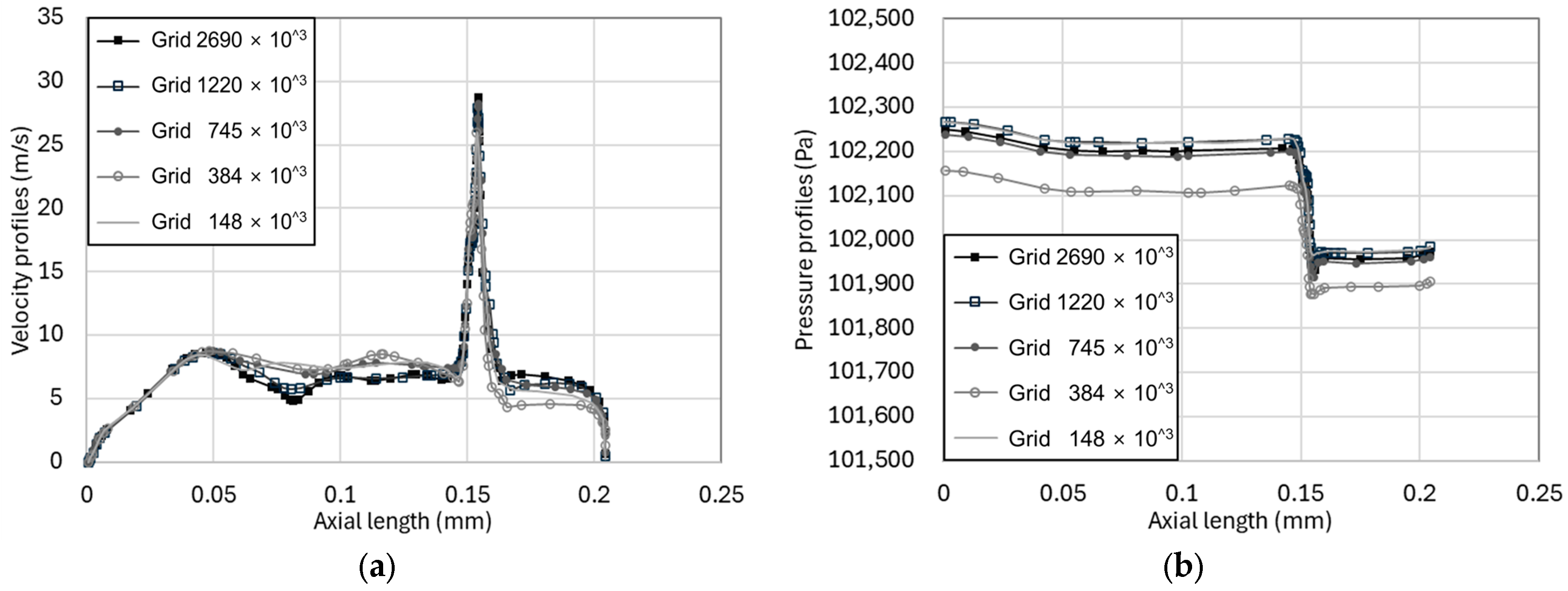
Mesh validation tests were performed to determine the appropriate number of grid cells required for generating accurate predictions of the flame shape. As shown in Table 2, the mesh validation tests were conducted using between 150,000 and 2.70 million cells, with an approximately 70–30% split between the fluid mesh and the solid mesh. Figure 4 shows the axial velocity profile and pressure profile of the flow field in the internal flow domain. In the velocity profile shown in Figure 4a, the results obtained using less than 745,000 cells are significantly different from those obtained using more cells. In addition, the results with 384,000 cells are not satisfactory. As shown in Figure 4b, the pressure profile obtained using 384,000 cells is significantly different from that obtained using more cells. Except for the aforementioned number of cells, since the pressure differences between the cells were within 0.00001% of the total pressure, the results obtained using other grid sizes were considered to be highly convergent. The results indicated that the number of cells would have to be set to 1.2 million or higher to ensure a valid analysis. Thus, we used 1,220,000–2,690,000 cells in the analysis models.

3.2. Internal Flow Characteristics

Figure 5 shows the differences in the velocity fields among the three header shapes. Because the combustor models had the same fuel slit, the fuel passing through the narrow slit attained the same axial flow velocity of about 20 m/s. Subsequently, the fuel was mixed with air and exhibited different flow fields corresponding to the different header shapes. In the case of the flat header, two inner recirculation zones (IRZs) were formed by the inner shear layers (ISLs) on the sides, which created vortices that focused the flame towards the center, helping with the formation of the thin flame. The overall flow was uniform, with a velocity of about 12 m/s in the combustion area. In the case of the concave header, due to its concave shape, a natural internal shear layer and a single internal recirculation zone were formed, with in the formation of the thin flame. A flow field with a central velocity of about 20 m/s was formed, creating a strong central flow. In the case of the convex header, the flow was concentrated in a direction perpendicular to the surface of the header and was dispersed diagonally.
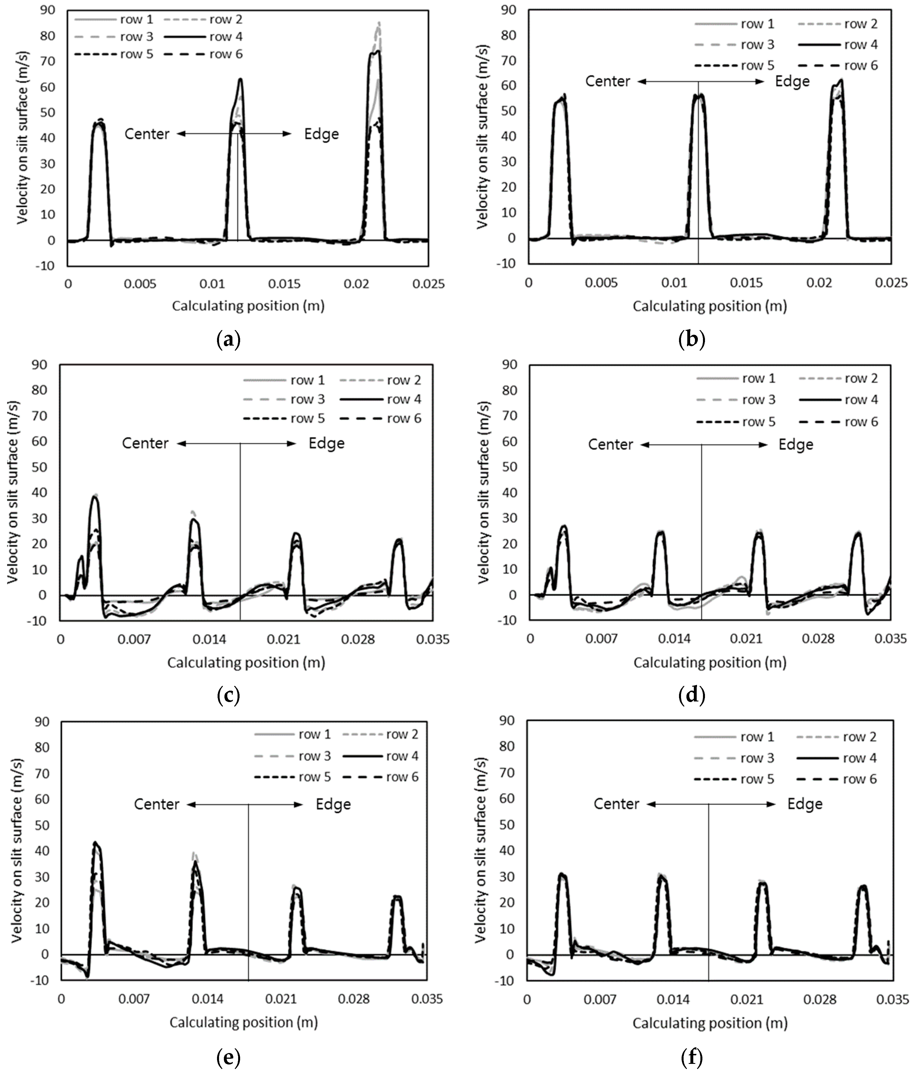
Figure 6 shows the axial velocity distribution from the central line to the edge line obtained by dividing the combustion surface into six rows (see Figure 1). Figure 6a,b show the velocity of the hydrogen–air mixed gas and methane–air mixed gas on the flat header surface. Because the flat header had the smallest gas hole area, the velocities in this header were the highest. Figure 6c and 6d, respectively, show the surface velocities of the hydrogen–air and methane–air mixed gases in the concave header, while Figure 6e and 6f, respectively, show the surface velocities of the hydrogen–air and methane–air mixed gases in the convex header. The average flow velocities were 20 m/s, and the central flow of the hydrogen–air mixed gas was more developed than that of the methane–air mixed gas. In the concave header, the development of the central flow caused the flame to form in the center, whereas in the convex header, it dispersed the flame outward.

3.3. Pressure Drop across Distribution Plates

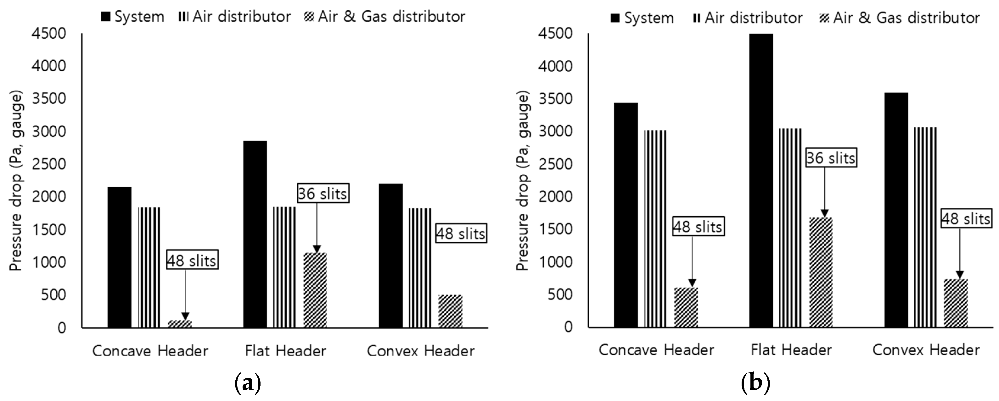
Since the premixed gas was supplied to the combustor using a blower, a pressure drop analysis was performed on the distribution plates with a high pressure drop. The pressure drops across the air distribution plate and mixed-gas distribution plate were analyzed along the airflow path, and the pressure drop across the entire system was compared among the three header shapes, as shown in Figure 7. The pressure drop across the air distribution plate was 1750 Pa for hydrogen combustion and 3000 Pa for methane combustion. Further, the flat header showed the highest pressure drop, as it had the fewest slit openings, while the concave header exhibited the lowest pressure drop due to its larger number of slit openings and its shape. The pressure drops across the entire system for the flat, convex, and concave headers were 2700 Pa, 2300 Pa, and 2150 Pa, respectively, for hydrogen combustion. The same order was observed for methane combustion as well, with the average pressure being 1500 Pa higher than that for hydrogen combustion. This was because the airflow rate for methane combustion is 29% higher than that for hydrogen combustion (see Table 1). Based on these results, the concave header is considered to be advantageous for the blower, as it exhibited the lowest pressure drop.

3.4. Flame Shape with Temperature and Residual Fuel Ratio

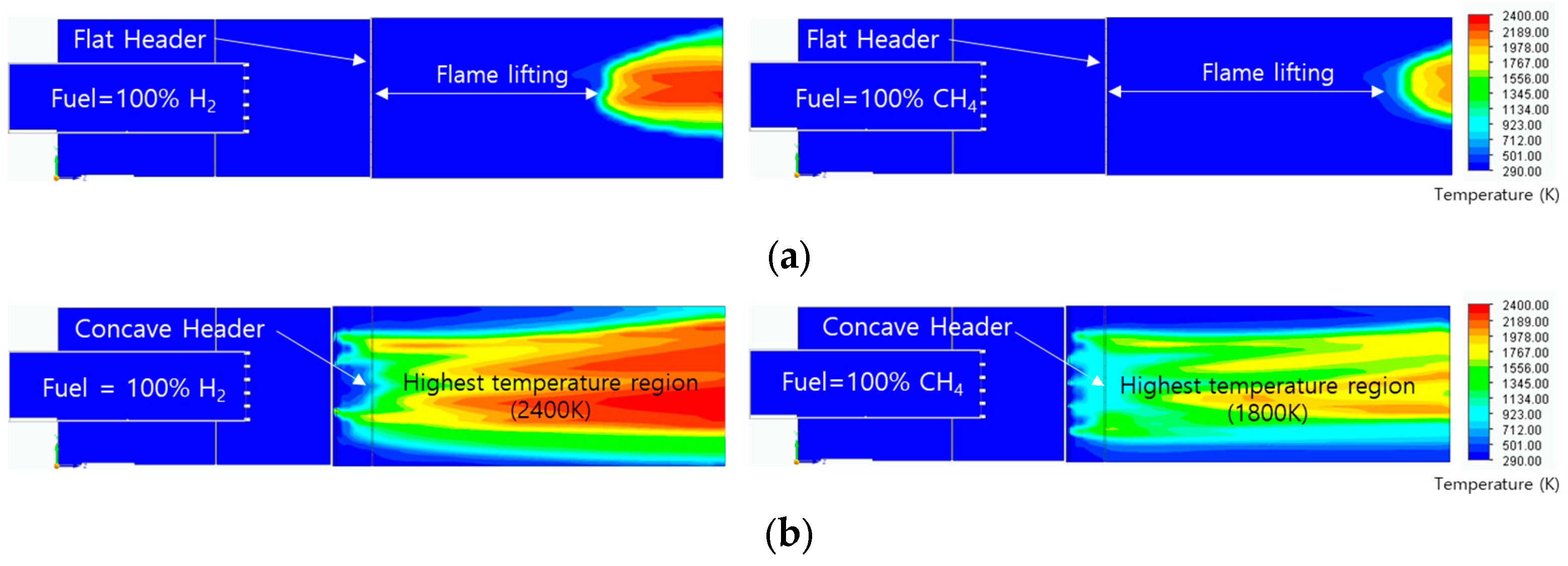
Hydrogen flames exhibit relatively low radiative heat transfer because the primary combustion product, water vapor, emits thermal radiation much less effectively than the carbon dioxide and soot particles found in the flames of hydrocarbons, such as methane. However, since FLOEFD calculates radiative heat transfer as a function of temperature, it may not accurately reflect the differences in radiative effects between hydrogen and methane flames. Therefore, the influence of radiation was neglected in this analysis. In terms of the ignition method, the ignition point was located 10 mm downstream of the combustor. After ignition, the ignition point was removed to avoid obstructing the flow behavior. A temperature field analysis was performed to predict the flame shapes for pure hydrogen and pure methane. The temperature field in Figure 8 covers temperatures of 293–2400 K. In the flat header, even if there was an inner recirculation zone that enhanced flame attachment, the flame was lifted from the combustor surface. This suggests that a lifting flame can be formed on a flat header under a high surface flow velocity of 50 m/s. Due to the high diffusion velocity of hydrogen, the hydrogen flame had a shorter lifting distance than the methane flame. In the concave header, the hydrogen and methane flames were stably attached to the combustor surface with the help of the inner recirculation zone and the flame-holding header shape. The temperature of the hydrogen flame was 600 °C higher than that of the methane flame. The convex header is considered to be unsuitable for use as a combustor, because the flame was dispersed beyond the required axial region.
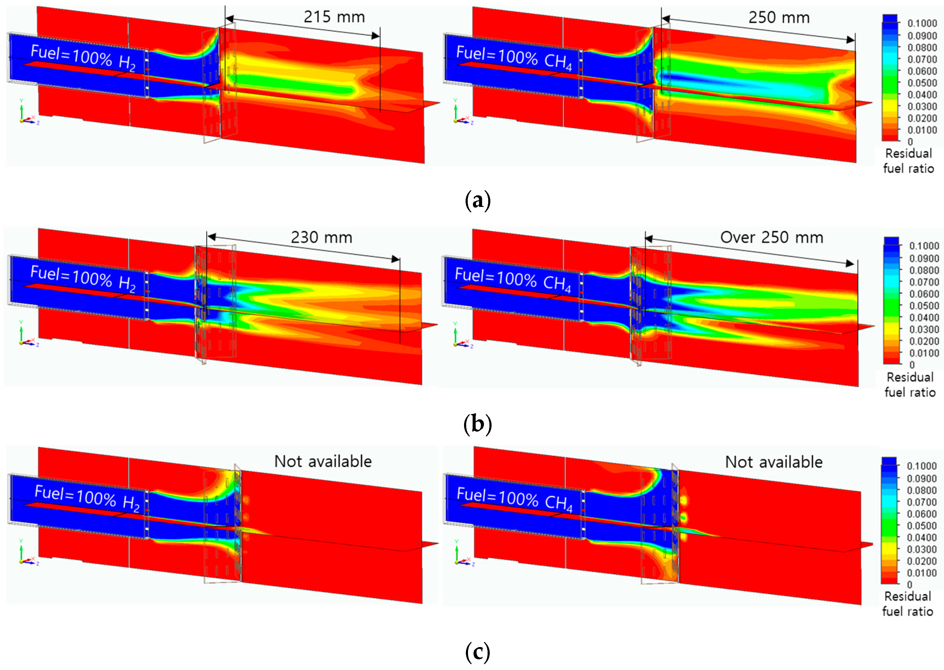
Figure 9 shows the flame quenching distances based on the amount of residual fuel. The mass fraction of residual fuel was set from 1% to 10%. In the flat header, residual fuel was observed over a long distance in the axial direction; however, considering the lifting flame, this distance cannot be regarded as the actual quenching distance. In the concave header, the residual fuel fraction was high on the combustor surface and then decreased along the axial direction. The flame quenching distances were 230 mm and over 250 mm for hydrogen and methane combustion, respectively. Although the flame quenching distance in the convex header could not be accurately calculated due to the flame dispersion, the hydrogen flame was observed to have a shorter quenching distance than the methane flame.

3.5. Exhaust Gas Composition

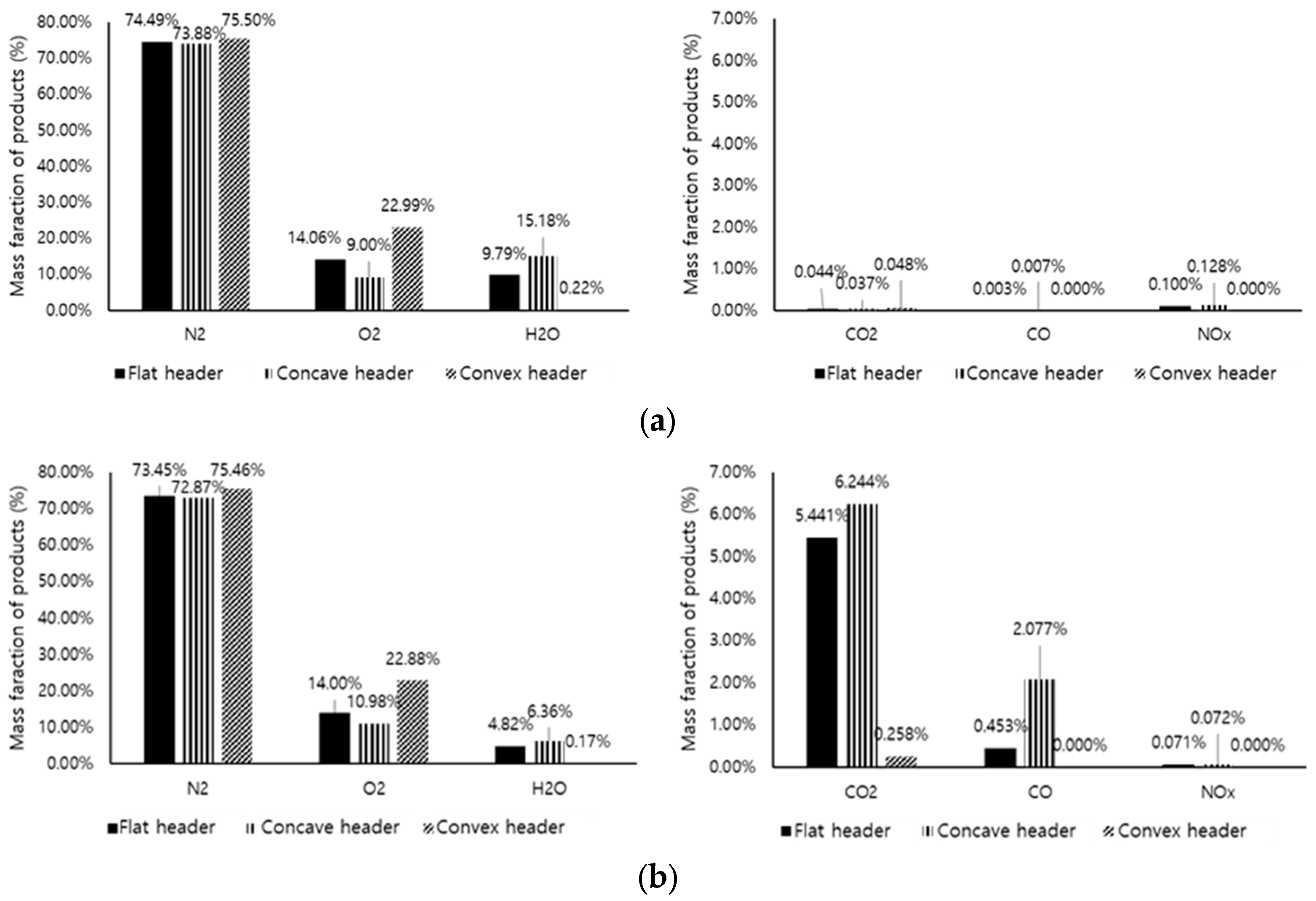
A comparative analysis was performed on the combustion products at the final outlet based on the shape, temperature, and mass fraction of the flame. Figure 10a,b present the combustion products of hydrogen and methane, respectively. The hydrogen combustion products had high H2O and NOx fractions, while the methane combustion products had high CO2 and CO fractions. Based on the analysis, hydrogen combustion resulted in higher temperatures, causing greater thermal NOx and H2O emissions. In addition, the concave header led to the lowest O2 fraction. This indicates that the concave header had a higher combustibility than the other header shapes. In the concave header, the NOx mass fraction for hydrogen combustion (0.128%) was about 1.78 times that for methane combustion (0.072%).

4. Conclusions

The findings from this study suggest that a thin-flame combustor design significantly influences hydrogen flame characteristics and combustion performance. The flame characteristics of hydrogen and methane were investigated via numerical simulations. Differences in flame shape and combustibility were observed between pure methane combustion and pure hydrogen combustion. Three combustor header shapes (flat, concave, and convex) were modeled to analyze their effects on flame behavior, and the results revealed that these different header shapes created distinct flow patterns, affecting the flame behavior. In the flat header, even if there was an inner recirculation zone that enhanced flame attachment, the flame was lifted from the combustor surface due to its high surface flow velocity. In the concave header, the hydrogen and methane flames were stably attached to the combustor surface with the help of the inner recirculation zone and the flame-holding header shape. Conversely, the convex header dispersed the flow outwards, resulting in less stable flame attachment. Therefore, the concave header showed the most stable flame temperature field with the shortest quenching distance. Based on the comparative analysis of the combustion products, hydrogen combustion led to greater temperatures and higher NOx fractions compared with methane combustion. The concave header exhibited a higher combustibility than the other header shapes, particularly for hydrogen combustion. These findings provide valuable insights for optimizing hydrogen combustor design in view of industrial applications, particularly in terms of enhancing combustion efficiency and minimizing emissions. In future work, we plan to validate the numerical results with experimental data once the prototype and facilities are ready. This validation will ensure the accuracy and reliability of our numerical findings.

Author Contributions

Conceptualization, Y.B.K. and Y.S.J.; methodology, J.L. and Y.B.K.; software, J.L.; validation, J.L.; formal analysis, J.L.; investigation, J.L.; resources, C.B.S.; data curation, J.L.; writing—original draft preparation, J.L. and Y.B.K.; writing—review and editing, Y.B.K.; visualization, Y.B.K.; supervision, Y.B.K.; project administration, C.B.S.; funding acquisition, C.B.S. All authors have read and agreed to the published version of the manuscript.

Funding

This work was supported by the Carbon Innovation Stars Project (20018190, Development of 0.5 ton/h Hybrid Hydrogen Burner with Slit flame) funded By the Ministry of Trade, Industry & Energy (MOTIE, Republic of Korea).

Institutional Review Board Statement

Not applicable.

Informed Consent Statement

Not applicable.

Data Availability Statement

The original contributions presented in this study are included in the article; further inquiries can be directed to the corresponding author.

Conflicts of Interest

This research was conducted Chang Bum Sohn is employed by Daeyeol Boiler Co. Ltd. and Young Sik Jeong is employed by Innoen Inc. in the absence of any commercial or financial relationships that could be construed as potential conflicts of interest.

Nomenclature

u Fluid velocity, m/s
ρ Fluid density, kg/m3
τ i j Viscous shear stress tensor, N/m2
S i Mass-distributed external force per unit mass, N/kg
μ Dynamic viscosity coefficient, N∙s/m2
μ t Turbulent eddy viscosity coefficient, N∙s/m2
k Turbulent kinetic energy, kg m2/s2
ε Turbulent dissipation, kg m2/s2
f Turbulent viscosity factor
P B Turbulence generation due to buoyancy forces, N
D m n Molecular matrices of diffusion
D m n t Turbulent matrices of diffusion
S m Rate of production or consumption, kg/s
y P Combustion products, mol
y ˙ P Reaction rate, mol/m3∙s
y F Mass fraction of residual fuel
y o Mass fraction of oxidizing agent
m F Molar mass of fuel, kg
m O Molar mass of oxidizing agent, kg
T i g n Ignition temperature, °C
ROne-way reaction rate, mol/m3∙s

References

  1. Kadowaki, S.; Hasegawa, T. Numerical simulation of dynamics of premixed flames: Flame instability and vortex–flame interaction. Prog. Energy Combust. Sci. 2005, 31, 193–241. [Google Scholar] [CrossRef]
  2. Sarli, V.D.; Benedetto, A.D. Laminar burning velocity of hydrogen–methane/air premixed flames. Int. J. Hydrogen Energy 2007, 32, 637–646. [Google Scholar] [CrossRef]
  3. Xiao, H.; Duan, Q.; Sun, J. Premixed flame propagation in hydrogen explosions. Renew. Sustain. Energy Rev. 2018, 81, 1988–2001. [Google Scholar] [CrossRef]
  4. Giannakopoulos, G.K.; Gatzoulis, A.; Frouzakis, C.E.; Matalon, M.; Tomboulides, A.G. Consistent definitions of “Flame Displacement Speed” and “Markstein Length” for premixed flame propagation. Combust. Flame 2015, 162, 1249–1264. [Google Scholar] [CrossRef]
  5. Takeno, K.; Kido, H.; Takeda, H.; Yamamoto, S.; Shentsov, V.; Makarov, D.; Molkov, V. Flame stabilisation mechanism for under-expanded hydrogen jets. J. Fire 2024, 7, 48–59. [Google Scholar] [CrossRef]
  6. Chakraborty, N.; Dopazo, C. Timescales associated with the evolution of reactive scalar gradient in premixed turbulent combustion: A direct numerical simulation analysis. J. Fire 2024, 7, 73–92. [Google Scholar] [CrossRef]
  7. Zhang, C.; Shen, X.; Wen, J.X.; Xiu, G. The behavior of methane/hydrogen/air premixed flame in a closed channel with inhibition. J. Fuel 2020, 265, 116810. [Google Scholar] [CrossRef]
  8. Halter, F.; Chauveau, C.; Gokalp, I. Characterization of the effects of hydrogen addition in premixed methane/air flames. Int. J. Hydrogen Energy 2007, 32, 2585–2592. [Google Scholar] [CrossRef]
  9. Okafor, C.E.; Hayakawa, A.; Nagano, Y.; Kitagawa, T. Effects of hydrogen concentration on premixed laminar flames of hydrogen-methane-air. Int. J. Hydrogen Energy 2014, 39, 2409–2417. [Google Scholar] [CrossRef]
  10. Funke, H.H.W.; Beckmann, N.; Abanteriba, S. An overview on dry low NOx micromix combustor development for hydrogen-rich gas turbine applications. Int. J. Hydrogen Energy 2019, 44, 6978–6990. [Google Scholar] [CrossRef]
  11. Cao, Z.; Lyu, Y.; Peng, J.; Qiu, P.; Liu, L.; Yang, C.; Yu, Y.; Chang, G.; Yan, B.; Sun, S.; et al. Experimental study of flame evolution, frequency and oscillation characteristics of steam diluted micro-mixing hydrogen flame. J. Fuel 2021, 301, 121078. [Google Scholar] [CrossRef]
  12. You, C.; Lee, H.; Hwang, S. Low NOX combustion characteristics by hydrogen micro jet flame in cross flow. J. Mech. Sci. Technol. 2023, 37, 445–455. [Google Scholar] [CrossRef]
  13. An, Q.; Kheirkhah, S.; Bergthorson, J.; Yun, S.; Hwang, J.; Lee, W.J.; Kim, M.K.; Cho, J.H.; Kim, H.S.; Vena, P. Flame stabilization mechanisms and shape transitions in a 3D printed, hydrogen enriched, methane/air low-swirl burner. Int. J. Hydrogen Energy 2021, 46, 14764–14779. [Google Scholar] [CrossRef]
  14. Schefer, R.W. Hydrogen enrichment for improved lean flame stability. Int. J. Hydrogen Energy 2003, 28, 1131–1141. [Google Scholar] [CrossRef]
  15. Esfahani, J.A.; Fanaee, S.A. Analytical modeling of hydrogen–air mixture in a catalytic microchannel. J. Thermophys. Heat Transf. 2015, 29, 274–280. [Google Scholar] [CrossRef]
  16. Edalati-nejad, A.; Fanaee, S.A.; Ghodrat, M.; Khadem, J. Investigation of unsteady premixed micro/macro counterflow flames for lean to rich methane/air mixture. J. Energy Resour. Technol. 2021, 143, 052302. [Google Scholar] [CrossRef]
  17. Edalati-nejad, A.; Fanaee, S.A.; Ghodrat, M. Numerical investigation of methane-air counterflow premixed flame into a newly designed plus-shaped chamber with platinum and rhodium catalysts coated walls. Combust. Sci. Technol. 2023, 195, 2598–2613. [Google Scholar] [CrossRef]
  18. Pourali, M.; Esfahani, J.A.; Fanaee, S.A.; Kim, K.C. Developing mathematical modeling of the heat and mass transfer in a planar micro-combustor with detailed reaction mechanisms. J. Therm. Anal. Calorim. 2021, 143, 2679–2694. [Google Scholar] [CrossRef]
  19. Bidabadi, M.; Montazerinejad, S.; Fanaee, S.A. The influence of radiation on the flame propagation through micro organic dust particles with non-unity Lewis number. J. Energy Inst. 2014, 87, 354–366. [Google Scholar] [CrossRef]
  20. Fanaee, S.A.; Esfahani, J.A. The analytical modeling of propane-oxygen mixture at catalytic micro-channel. Heat Mass Transf. 2014, 50, 1365–1373. [Google Scholar] [CrossRef]
  21. Somers, L.M.T.; Goey, L.P.H. A numerical study of a premixed flame on a slit burner. Combust. Sci. Technol. 1995, 108, 121–132. [Google Scholar] [CrossRef]
  22. Guo, L.; Zhai, M.; Shen, Q.; Qi, H.; Dong, P.; Zhu, J. Methane-air partially premixed flame behaviors in a micro plate slit. Chem. Eng. Process. Process Intensif. 2020, 158, 108200. [Google Scholar] [CrossRef]
  23. Liu, T.; Yang, L.; Qin, L.; Jiang, X.; Li, J. Models of the time-averaged heat release rate of the two-dimensional laminar premixed slit flame subjected to the transverse disturbance. Aerosp. Sci. Technol. 2023, 132, 108072. [Google Scholar] [CrossRef]
  24. Raghavan, K.A.S.; Rao, S.S.; Raju, V.R.K. Numerical investigation of the effect of slit-width on the combustion characteristics of a micro-combustor with a centrally slotted bluff body. Int. J. Hydrogen Energy 2023, 48, 5696–5707. [Google Scholar] [CrossRef]
  25. Chen, P.; Luo, G.; Sun, Y.; Lv, Q. Impacts of plate slits on flame acceleration of premixed methane/air in a closed tube. J. Energy Inst. 2018, 91, 563–572. [Google Scholar] [CrossRef]
  26. Tyagi, A.; Boxx, I.; Peluso, S.; O’Connor, J. The role of flow interaction in flame–flame interaction events in a dual burner experiment. Proc. Combust. Inst. 2019, 37, 2485–2491. [Google Scholar] [CrossRef]
  27. Mentor Graphics Corporation, FloEFD Technical Reference Software Version 17. 2018. Available online: https://www.smart-fem.de/media/floefd/TechnicalReferenceV17.pdf (accessed on 20 August 2024).
  28. Zeldovich, Y.B.; Barenblatt, G.I.; Librovich, V.B.; Makhviladze, G.M. The Mathematical Theory of Combustion and Explosions; Springer: New York, NY, USA, 1985. [Google Scholar]
  29. Siriganano, W.; Merzhabov, A.; De Luca, L. Advances in Combustion Science in Honor of Ya. B. Zeldovich; American Institute of Aeronautics and Astronautics Inc.: Reston, VA, USA, 1996. [Google Scholar]
Figure 1. Combustor configuration and distribution plate design.
Fire 07 00361 g001
Figure 2. Three types of combustor headers.
Fire 07 00361 g002
Figure 3. Analysis area of combustor model.
Fire 07 00361 g003
Figure 4. Mesh validation test results: (a) velocity profile and (b) pressure profile.
Fire 07 00361 g004
Figure 5. Flow velocity fields: (a) flat header, (b) concave header, and (c) convex header.
Fire 07 00361 g005
Figure 6. Velocity distributions from center line to boundary line of combustor surface: (a) hydrogen flat header, (b) methane flat header, (c) hydrogen concave header, (d) methane concave header, (e) hydrogen convex header, and (f) methane convex header.
Fire 07 00361 g006
Figure 7. Pressure drops across different distribution plates and header shapes: (a) hydrogen combustion and (b) methane combustion.
Fire 07 00361 g007
Figure 8. Temperature field of hydrogen and methane flames: (a) flat header, (b) concave header, and (c) convex header.
Fire 07 00361 g008aFire 07 00361 g008b
Figure 9. Flame quenching distance based on residual fuel ratio field of 1–10%: (a) flat header, (b) concave header, and (c) convex header.
Fire 07 00361 g009
Figure 10. Mass fractions of combustion products: (a) hydrogen combustion and (b) methane combustion.
Fire 07 00361 g010
Table 1. Design parameters for methane–air mixed gas and hydrogen–air mixed gas.
Design ParameterCH4H2
Required heat input40,000 kcal/h40,000 kcal/h
Fuel flow rate4.5 Nm3/h13.8 Nm3/h
Higher calorific value8698 kcal/Nm32796 kcal/Nm3
Fuel inlet temperature15 °C15 °C
Combustion air flow rate55.0 Nm3/h42.8 Nm3/h
Mixture flow rate59.5 Nm3/h56.6 Nm3/h
Excess air ratio1.31.3
Reynolds number49054665
Table 2. Number of cells in mesh validation test.
Total Number of CellsNumber of Fluid CellsNumber of Solid Cells
147,95383,23764,716
384,030214,906169,124
745,486425,719319,767
1,220,378765,356455,022
2,691,0361,800,925890,111
Disclaimer/Publisher’s Note: The statements, opinions and data contained in all publications are solely those of the individual author(s) and contributor(s) and not of MDPI and/or the editor(s). MDPI and/or the editor(s) disclaim responsibility for any injury to people or property resulting from any ideas, methods, instructions or products referred to in the content.