1. Introduction
In recent years, bioenergy has garnered particular interest, mainly due to the excessive consumption of fossil fuels, which, in addition to having limited availability, involve conversion processes which are associated with high emissions of pollutants into the atmosphere [
1,
2].
Biomass, in its most natural state, has been used since the dawn of humanity as an energy source; however, its application is still insufficient in some regions of the world [
3]. This energy resource has the particularity of being used directly in the production of thermal or electric energy [
4], or being converted into gaseous, liquid, or solid fuels via physical, chemical, or biological processes [
5]. This flexibility allows biomass to directly compete with fossil fuels, as well as other renewable energy sources [
6]. One of the significant advantages of using biomass as fuel is its carbon-neutral character in terms of CO
2 emissions, as it does not contribute to an increase in atmospheric CO
2 levels when processed through sustainable means [
7].
Currently, biomass can be converted into useful energy through several technologies, enabling the use of fuels in different physical states with high levels of applicability [
8,
9]. Nonetheless, this traditional energy source is frequently considered inefficient [
10].
Combustion remains the most widely used process in the direct conversion of biomass [
9]. However, when used improperly, it is also responsible for the release of considerable amounts of pollutants, including carbon monoxide, nitrogen oxides, hydrocarbons, and solid particles [
11].
The combustion in fixed beds, especially the simplest type, is the most common system in the thermochemical conversion of biomass for small-scale applications, typically used in fireplaces, wood stoves, or pellet boilers [
12]. Fixed-bed combustion has many variants, including static or stationary, moving, traveling, rotating, and vibrating grate technologies; the choice of grate type depends, among other factors, on the type of fuel used [
8].
The grate combustion system enables the burning of a wide range of fuels with diverse properties and moisture contents. Despite the long-standing use of this technology, its study remains of significant importance, as the available information during the combustion of solid fuels is still insufficient [
13]. This technology exhibits some flexibility regarding variations in fuel quality, although it responds slowly to changes in load and, as its main drawback, presents challenges in combustion control [
14]. Particularly, fixed and traveling grates are not suitable for burning fuel mixtures, due to the challenge of ensuring a uniform blending along the grate; only the vibrating and rotating grate configurations allow for better fuel mixing [
8]. The static grate technology is typically used in small-capacity boilers, where the fuel is burned on a bed where the grate is fixed in space [
15]. The fuel and primary air must be evenly distributed along the grate, and the fuel transport should be as smooth and homogeneous as possible in order to prevent the formation of fly ash and unburned particles [
8]. Despite being common, fixed-bed combustion is complex and challenging to control, representing a combustion process which is influenced by a significant array of parameters [
12]. In the case of traveling grate combustion, the fuel is burned along a grate that undergoes a cyclical movement [
15]. Traveling grates are suitable for continuous burning, as the fuel can be fed from one end of the grate, and ashes can be removed from the other [
12]. This technology allows for the better control of the combustion process and carbon-burning efficiency, enabling co-combustion and the use of fuels with varying moisture and carbon content [
13,
16]. Traveling grate combustion has been extensively used in industrial plants for waste incineration in China [
17]. Despite the wide applicability of these combustion systems, challenges persist during the combustion process, particularly concerning the effectiveness of fuel burning and fuel and oxidizer mixing within the bed [
16].
Biomass exhibits a highly heterogeneous and, at times, complex composition, which imperatively influences its performance as a fuel [
18]. Its combustion is a highly complex process; the design and optimization of combustion systems require extensive knowledge of the fuel properties and their influence [
19]. Hence, the need to assess the different types of biomass combustion becomes pertinent and essential for efficient conversion. The design of combustion systems and the selection of operational parameters should be strongly influenced by the fuels’ properties [
20]. As the furnace is the most relevant element in combustion systems, its optimization is crucial and should align with the variability of biomass.
In the biomass combustion process, the burning of the solid carbonaceous residue accounts for a significant part of the total burning time [
21]. Moreover, it is during this phase that a substantial amount of energy is released [
8], meaning this stage is of considerable importance.
During the literature review conducted in this study, relevant works in biomass combustion in fluidized beds, specifically charcoal [
22,
23,
24,
25], were identified, along with several works developed in chemical kinetics [
26,
27,
28,
29]. However, the investigation of charcoal burning in other combustion systems, such as the traveling bed system, is still limited and requires additional analysis.
Considering the aforementioned facts, conducting studies on charcoal burning in various combustion systems becomes of particular interest. Where possible, establishing connections in terms of kinetic and diffusive results will be valuable. The determination and laboratory-scale analysis of kinetic and diffusive data which is characteristic of the combustion reaction of the solid carbonaceous residue is essential for research and for the design of combustion systems; this is why the topic of the current study is also relevant in this context.
This work intended to study the combustion process of biochar pellet loads in a traveling grate furnace and quantify the diffusive parameters, specifically determining the short circuit fraction observed in the furnace supply air. The information obtained from burning biochar in a traveling bed may contribute to a better understanding of the combustion mechanisms of ligneous biomass, specifically the combustion of wood char.
2. Combustion Model
In the mid-1970s, Kanury [
30] introduced a coal combustion model, which was applied to fixed-bed reactors. The author assumed that carbon combustion occurred solely via pure diffusion; however, more recent studies do not support this theory. Based on this model, Pinho et al. [
31], in a preliminary theoretical-practical analysis that led to the present study, developed a mathematical model for char combustion in a fixed bed, where kinetic phenomena are considered. By applying this model to the combustion tests in a traveling fixed bed, and based on the kinetic information obtained from fluidized bed combustion experiments conducted by the same research team [
32], it was possible to determine the bypass factor, which is the characteristic diffusive parameter of the process.
The traveling grate combustion will be analyzed as a furnace with a well-mixed gas phase, where the supply air is short-circuited at the furnace entrance, dividing into two flows. One flow will be fed by χ of oxygen, which will pass directly to the exit; the remaining will be fed by (1 − χ) of oxygen, effectively supplying the reaction zone. In other words, there is a bypass of the combustion air due to poor mixing in the reaction zone.
A mathematical treatment similar to the previous one [
31], but in which
is now replaced by (1 − χ)
, will allow the burning time, Equation (1), for this situation to be obtained.
where
is the mass of carbon per unit volume of particles,
f is the burned mass fraction,
is the initial diameter of the particles,
is the molar mass of carbon,
Sh is the Sherwood number,
η is the interparticle competition parameter,
i is the factor that takes the value of 1 when the CO combustion to CO
2 takes place closer to the particle surface or 2 when this gaseous phase reaction takes place away from the particle surface,
is the oxygen diffusivity in the burning gas,
is the heterogeneous reaction rate constant,
is the average furnace air velocity, and
is the furnace section area.
The bypass parameter χ ranges between 0 and 1, indicating the short-circuit fraction in the furnace’s supply air. The burning time of a specific batch will be minimal when the bypass parameter is zero, indicating a good use of the oxygen contained in the supply air. As the bypass parameter rises, the burning time of the load increases and, at the limit, when the bypass parameter is 1, the burning time will tend to approach infinity.
This burning model can be used to design or collect experimental data on the burning of small batches of carbon particles, particularly carbonized pellets.
Since, in principle, when carbonized pellets are burned, their initial diameters are above 1 mm, and the temperature is high, the burning will be of CO
2 right at the surface of the particle,
i = 1 [
31,
33]. The tests do not need to guarantee complete burning; reaching 70 or 75% of the burned mass fraction is enough. Also, combustion tests should not be carried out beyond 75% of the burned fraction, since, in the final phase of combustion, the diameter of the particles will be reduced, and there may only be CO burning on the surface of the particles, which should be avoided. Furthermore, the weight of this final part in the total calculation of the burn will eventually not be significant; as such, even if in some circumstances
i = 1 continues to be considered for the design of these solid burning systems, the resulting error will not be relevant, especially if the initial particle diameter is well above 1 mm.
The burning time tf can be obtained through measuring the time it takes for a specified mass load mc to achieve a defined mass fraction burned f. Conducting previous experiments involving the burning of loads of the same biochar in a bubbling fluidized bed furnace has provided kinetic data. When incorporated into the translational fixed-bed analysis, these kinetic data enable the calculation of the bypass parameter χ, which characterizes the furnace with a well-mixed gas phase.
3. Materials and Methods
3.1. Biochar Preparation and Characterization
The biochars used in the combustion tests were obtained from
Pinus pinaster,
Acacia dealbata, and
Cytisus scoparius pellets.
Pinus pinaster pellets were obtained from a Portuguese manufacturer, called Pellets Power, whereas
Acacia and
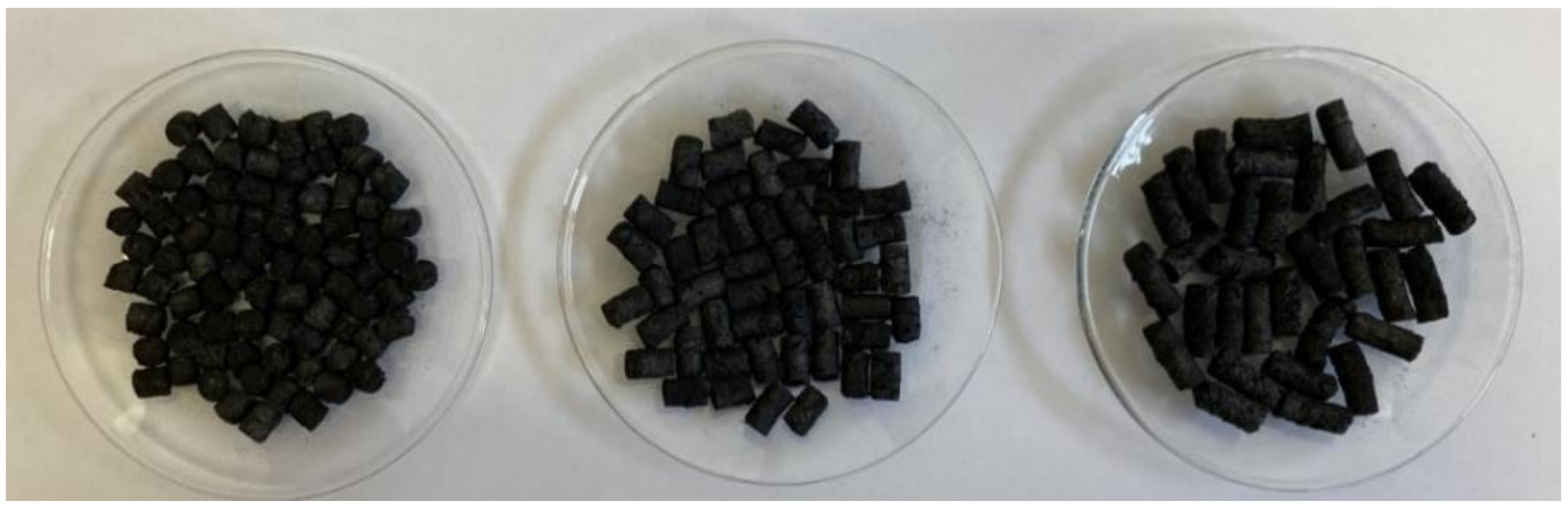
Cytisus pellets were specifically produced for this study at the laboratory facilities of the Polytechnic Institute of Viseu (Instituto Politécnico de Viseu). The forest species were harvested from a local forest in the Viseu region, and then subsequently dried in a solar kiln. A knife mill, Retsch SM 100, from Retsch GmbH, Germany, was employed to ground the dry raw material, which was subsequently characterized based on the moisture content and particle size. Afterward, pellets with a 6 mm diameter were manufactured using a Tojaltec pelletizer press machine, from Tojaltec, Portugal. Then, batches of 300 g of the three types of pellets were carbonized in a fixed bed at 800 °C under a nitrogen atmosphere. The biochar pellets were cut into uniform particles with average lengths between 4–5, 7–8, and 11–12 mm.
Figure 1 shows the finalized
Acacia dealbata char pellets in the three different sizes.
The biochar exact dimensions were determined from digital photographs using the ImageJ software version 1.51, following the procedure referred to in a previous work [
34]. For this purpose, each batch was weighed using a Sartorius BP 310P digital balance, from Sartorius, Göttingen, Germany, and labeled. The equivalent pellet diameter, defined by the sphericity and Sauter mean diameter, was determined for each pellet batch.
The critical properties of char pellets, specifically the proximate analysis, relevant to the present study were determined by the National Laboratory of Energy and Geology in Lisbon. These results are presented in
Table 1.
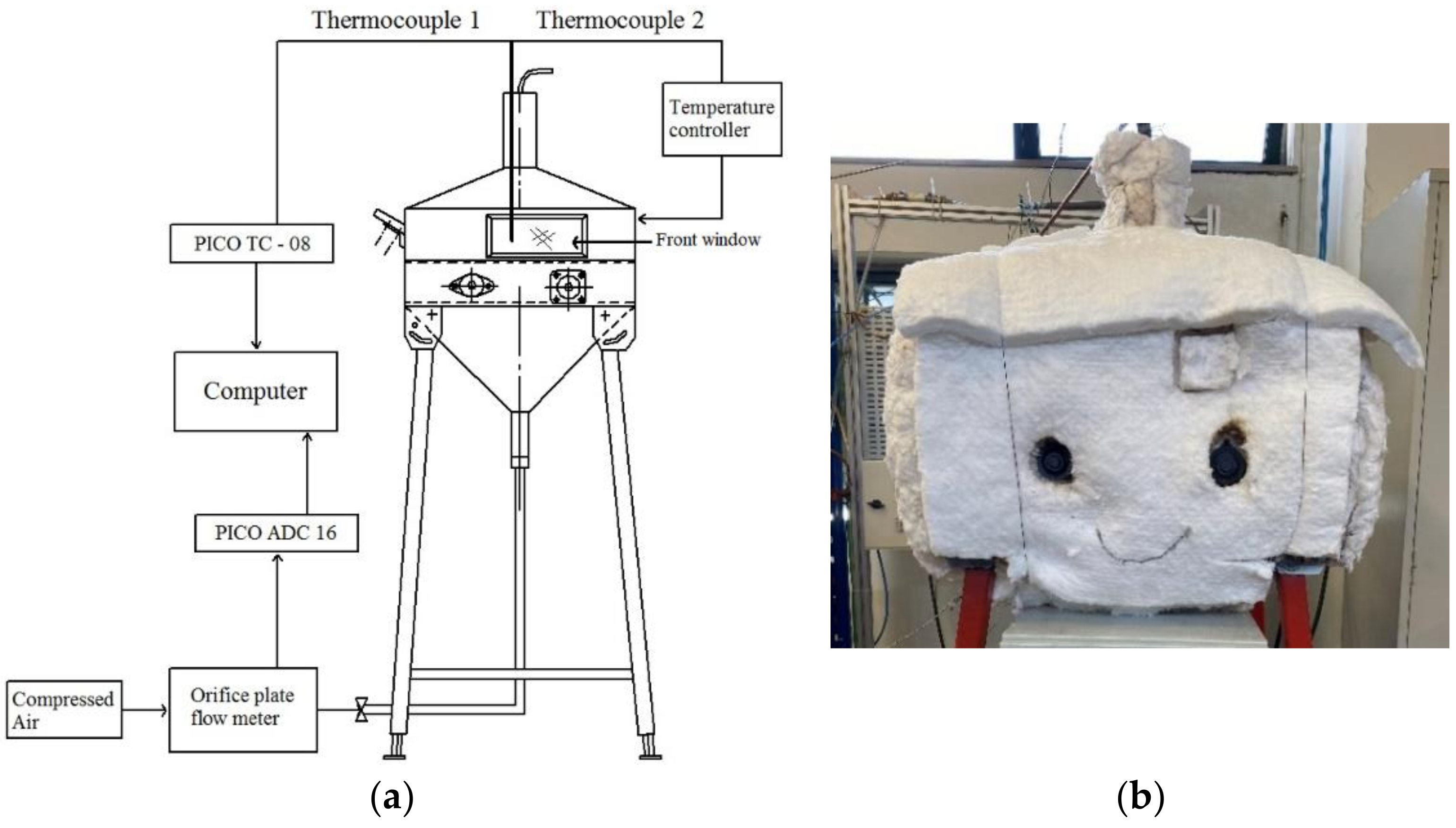
3.2. Experimental Setup
The experiments were conducted in a traveling grate furnace, as illustrated in
Figure 2. This furnace comprised a set of instruments enabling the measurement and control of parameters, such as furnace temperature, inlet air mass flow rate, and exhaust gas concentration. Ferreira et al. [
35] also used this experimental setup in a preliminary study investigating the spontaneous ignition of some ligneous biomass pellets.
The furnace body was made of ST37 carbon steel with internal dimensions of 610 mm in length, 320 mm in width, and 4 mm in thickness. The front section contained a high-temperature glass door, measuring 23 mm in length and 9 mm in width, providing access to the inside of the furnace.
Fuel feeding was conducted on the left side via a gutter fabricated from ST37 carbon steel; the ash outlet gutter was positioned on the opposite side and was made of the same material. A collector was placed at the furnace ash outlet drain to facilitate the collection of unburned fuel and ash produced during the combustion process.
The traveling grate was made from 300 mm long refractory stainless steel between axes and was 90 mm wide. The traveling grate speed was regulated using a potentiometer, and a constant speed of 18 mm/min was used in the present combustion tests.
The furnace heating system consisted of an electric resistance made from a 1.14 mm diameter Kanthal wire, coiled in a spiral, with a power of 4.5 kW. The furnace was thermally insulated with a Kaowool ceramic blanket and internally lined with pressed cordierite refractory plates in order to enhance its abrasion resistance.
The furnace temperature was controlled by an Omron ESCSV temperature controller. Measurements were conducted using two K-type thermocouples, both coated with 3 mm diameter and 1500 mm long stainless-steel sheaths. The thermocouples were positioned in the middle of the traveling grate at a height of 10 mm above the bed. One of the thermocouples was connected to the temperature controller, while the other was connected to a data acquisition system, Pico TC-08, equipped with cold junction compensation. This setup enabled the recording of temperature data during the combustion tests.
The air mass flow rate, sourced from the compressed air network and appropriately filtered and dehumidified, was measured with an orifice plate flow meter using both an Omega PX143-2.5BD5V pressure differential transducer and a U-tube pressure manometer. The pressure transducer was powered by a Matrix MPS-3005D 8 V DC power supply, which was linked to a Pico ADC-16 data acquisition system. The acquisition systems were connected to a computer via RS232 ports, and Pico Technology Ldt’s PicoLog 6 software was used for visualizing and storing the acquired data. The sampling rate used was 1 Hz. The orifice plate flow meter was previously calibrated using the tracer gas dilution method.
A stainless-steel probe, comprising a four-tube chamber with an external diameter of 10 mm and featuring six holes of 1 mm diameter and one central suction tube with the same dimensions, was employed to collect the exhaust gases. The probe analyzer was positioned in the furnace at a bed height of 350 mm.
The molar concentrations of the combustion gases, namely oxygen, carbon monoxide, carbon dioxide, and nitrogen oxides, in the combustion gases were continuously measured and recorded using a Testo 350 gas analyzer. The concentrations were recorded every 5 s.
The average uncertainty values for the experimental measurements have been calculated and are shown in
Table 2. These values represent the overall uncertainty derived from quantifying both random and systematic errors associated with the measurements, as well as the processes of data acquisition and conversion [
36].
3.3. Experimental Procedure
The adopted experimental procedure aimed to determine the burned mass fraction of a specific biochar batch and its corresponding burning time. The batch was collected at the end of its journey via the traveling grate, the burning time was recorded, and the collected sample was subsequently weighed.
The start-up of the experimental setup involved activating the furnace heating system and adjusting the temperature controller to the desired temperature set point. The water level in the U-tube water pressure manometer was immediately adjusted, and the pressure transducer was connected to measure the inlet air mass flow rate through the corresponding orifice plate. Next, the data acquisition systems were turned on.
Once the furnace temperature stabilized at the desired value, the gas analyzer was switched on, and the combustion tests began. A 4 g batch of char pellets, pre-weighed and characterized, was placed in the feeder and introduced into the furnace via the feed zone. Simultaneously, a stopwatch was started, and the feeder was subsequently removed from inside the furnace. The batch of char pellets moved along the furnace, carried out by the traveling grate, while burning, until the batch reached the outlet drain. Upon the batch’s complete fall into the collector placed at the furnace ash outlet drain, the stopwatch was halted. Subsequently, the collector was removed from the traveling grate furnace and transferred to a cooling chamber which was filled with nitrogen. Following the cooling process, the biochar batch was weighed, packaged, and labeled. The weighing process was carried out using a Sartorius BP 310P digital balance.
4. Results and Discussion
As previously mentioned, three types of charcoals obtained from the pyrolysis process performed on
Pinus pinaster,
Acacia dealbata, and
Cytisus scoparius pellets were used in these combustion tests. The chars were burned at two different temperatures, 700 and 800 °C, using three different particle sizes—the same average sizes previously used in the fluidized bed and stationary fixed-bed combustion studies conducted by the same team [
32]. For
Cytisus scoparius chars, tests were also conducted at 750 °C.
For each test condition, including char species, size, and temperature inside the furnace, three representative tests were selected. An exception was made for the tests conducted at 750 °C, where only two tests of each condition were chosen, due to the smaller overall number of tests performed under this specific condition.
The various tests were categorized based on their average particle sizes, namely 4–5, 7–8, and 11–12 mm. The descriptions E1, E2, and E3 correspond to the different tests performed, as shown in
Table 3,
Table 4 and
Table 5.
The average equivalent diameter of the char pellets was similar across the different sizes used, ranging between 4.48 and 5.77 mm for Pinus pinaster, 4.71 and 6.09 mm for Acacia dealbata, and 4.83 and 6.50 mm for Cytisus scoparius chars. Regarding the particle sphericity, the average values ranged between 0.80 and 0.87 for the Pinus pinaster loads, and between 0.81 and 0.87 for the Acacia and Cytisus.
As previously mentioned, the fixed-bed translational burning tests consisted of placing char pellets loads with a mass of 4 g inside the traveling bed furnace at temperatures of 700, 750, and 800 °C. These values indicate the initial bed temperature before load placement.
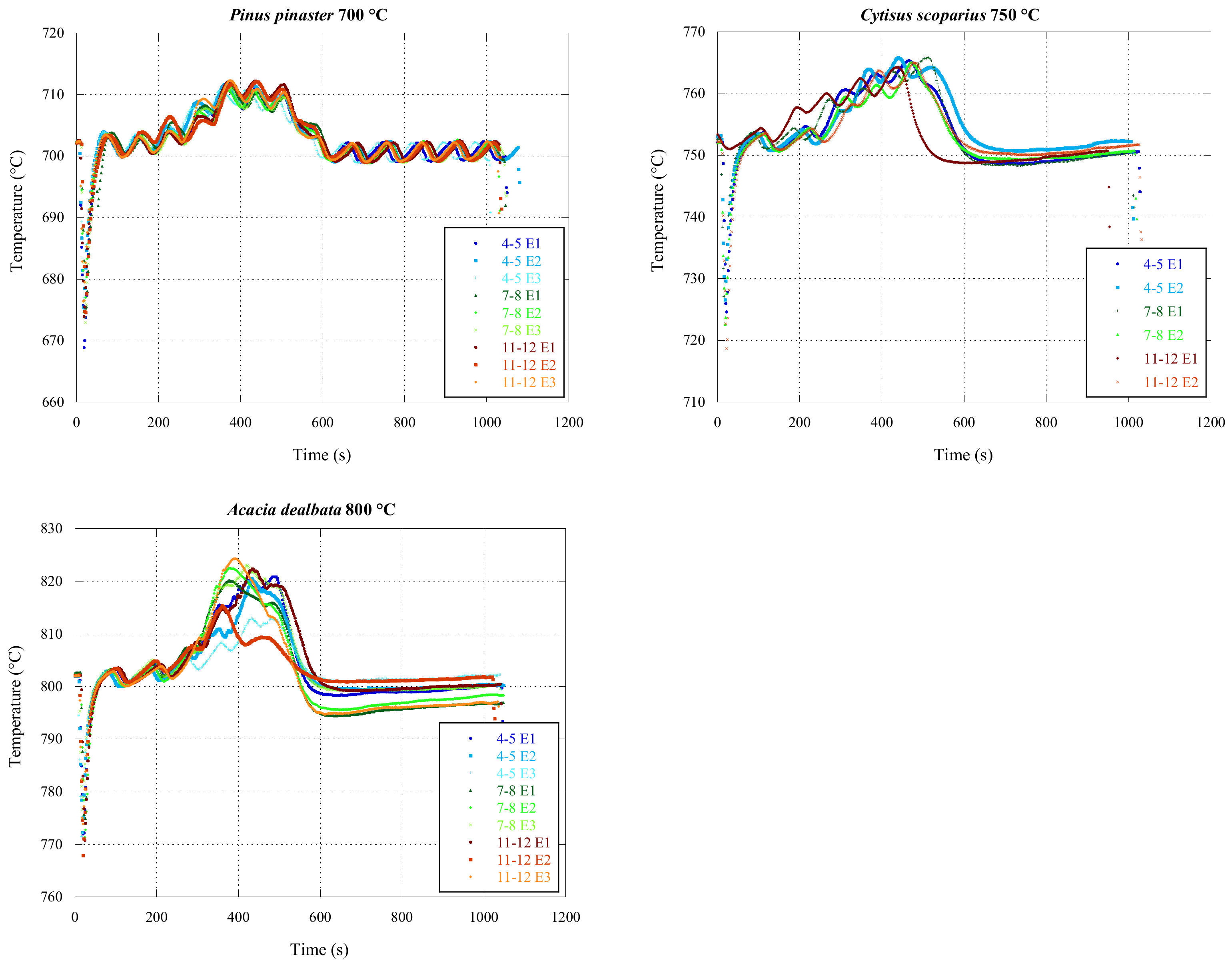
4.1. Furnace Temperature
The temperature inside the traveling bed furnace was measured and recorded at one-second intervals during all combustion tests.
Figure 3 illustrates the temperature evolution curves inside the furnace for the selected tests, grouped by char type and size.
The temperature curves exhibit a similar appearance regardless of the char type and size. However, the same was not true for the bed temperature; during the tests performed at 700 °C, following 10 min of testing, a more pronounced oscillation was apparent. At this temperature, maintaining a stable burner operation around the designated setting value proved challenging.
The abrupt temperature drop observed at the start of the tests resulted from the opening of the burner and the placement of the char loads, which initially took place at room temperature. However, this decrease was promptly recovered, and the temperature slightly exceeded the established set point. Subsequently, this gradually stabilized towards the set point as the test ended.
The combustion process of the char pellets began with heating, followed by the drying and releasing of volatile species (which, due to the low content, were irrelevant), and then the char combustion was initiated [
25,
37]. Typically, this phase began between 200 and 250 s after the introduction of the batch, with the peak temperature being reached approximately between 350 and 450 s.
4.2. Combustion Gases Analysis
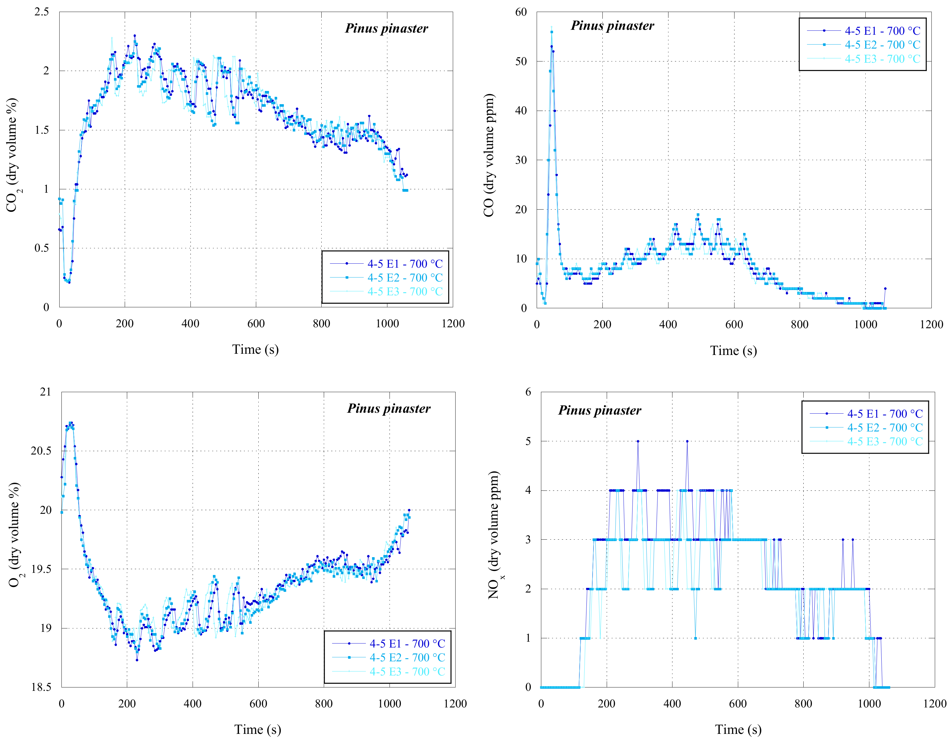
For a more comprehensive analysis of the incomplete burning behavior of char loads, the evolution of the volume fraction of carbon dioxide, carbon monoxide, oxygen, and nitrogen oxides resulting from the combustion of char pellets were recorded over time.
This analysis is not directly applied in the study of kinetic and diffusive parameters that characterize the char combustion in a translational fixed bed, but its execution was chosen to allow for the characterization of the emissions arising from the process.
In the above figures, specifically in
Figure 4, CO
2, CO, O
2, and NO
x emissions for the
Pinus pinaster char pellets burned at 700 °C with a particle size of 4–5 mm can be observed.
The exhaust gas analysis revealed stable combustions with low emissions of CO and NOx, as expected. The CO2 evolution curves primarily depend on temperature and particle size. Additionally, in the remaining tests, not illustrated in the figure, higher combustion temperatures corresponding to higher values of CO2 percentages were observed, and smaller particle sizes also resulted in higher volume fractions of CO2. In the tests represented, as the temperature and size of the biochars were the same, this trend is not clear.
4.3. Burning Time and Burned Mass Fraction
The burning time was recorded using both the data recording rate and, with increased accuracy, a digital stopwatch. This procedure allowed for the determination of partial burning times, which, in turn, allowed for the subsequent calculation of the bypass parameter.
To calculate the bypass parameter, a characteristic of translational fixed-bed combustion, the burned mass fraction f in each test needs to be determined.
This calculation involved the use of the experimental data collected during the combustion tests. For each test, the final mass of the batch
was recorded, enabling the determination of the burned mass fraction at the end of the burning time
tf, according to Equation (2).
where the mass of carbon consumed,
mC consumed, is given by
where
mashes and
mvolatile represent respectively the mass of ash and volatile matter present in the biochar batches, obtained according to the pellet char immediate analysis, which is set out in
Table 1.
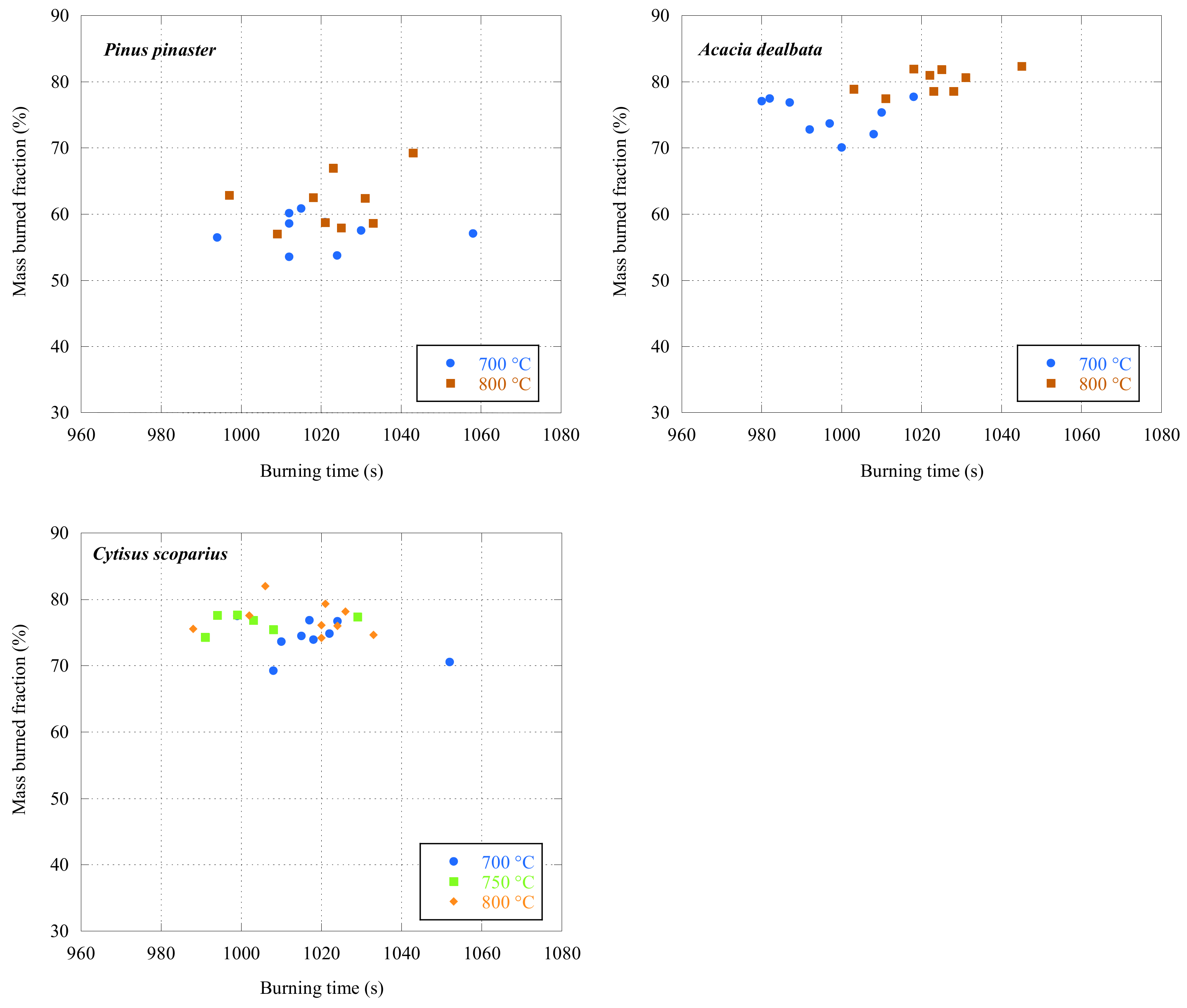
For all three species,
Figure 5 depicts the burned mass fraction as a function of the burning time.
The obtained burning times were analogous; this result was predictable since the same traveling grate speed was used in all experimental tests, which allowed the different batches to have a similar residence time. The difference between the burning times may be related to the way in which the char batches were positioned on the traveling grate. Despite the utmost care with which they were placed inside the burner, it was impossible to arrange them all in the same way; this led to small differences in the stacking and distribution of the char pellets on the grate.
The shortest burning time, 980 s, was obtained for Acacia dealbata, test 7–8 E3, at 700 °C, and the longest burning time, 1058 s, was achieved for test 4–5 E2 of Pinus, also at 700 °C. In fact, what varies most significantly is the burned mass fraction. That is, for close residence times, the burned mass fractions cover a much larger spectrum, as seen below.
As expected, an increase in the furnace temperature resulted in a higher burned mass fraction for all three chars. On average, the Pinus pinaster chars presented lower burned mass fractions, while Acacia dealbata chars had higher values. The burned mass fraction obtained in the tests ranged from 53.55% for Pinus to 82.35% for Acacia char pellets.
The fact that Pinus pinaster pellets exhibit lower burned mass fractions under the same combustion conditions may be related to their higher density when compared to the other tested char species. Conversely, Acacia was the species that showed a lower mass density and, therefore, a higher burned mass fraction. Charcoals with lower densities are inherently more fragile and will therefore experience more breakages during their feeding into the traveling grate furnace. This results in a batch containing smaller particles, which, in turn, accelerates the burning process.
On average, tests with Pinus pinaster chars had a higher burned mass fraction for the 11–12 mm sizes. Conversely, with Acacia and Cytisus pellets, the opposite was true, as the smaller particle size charges (4–5 mm) showed higher burned mass fractions.
The burned mass fraction obtained in Acacia and Cytisus chars aligns more consistently with the expectations. Char batches with large particles inherently have fewer particles, resulting in a lower total burn surface area and, consequently, lower burned mass fractions. For Pinus pinaster chars, it is assumed that higher density reverses this logic. The smaller sized Pinus chars, compared to the larger ones, are even more compact and mechanically stronger, ruling out the possibility of fragmentation.
Comparing the tests performed with the same species and the same average particle size reveals slight variations in the burned mass fraction, with an average standard deviation of less than 2%. Inevitably, a certain heterogeneity in the biomass and corresponding chars can lead to such variations. Also, the feeding of the char batches and, consequently, their arrangement on the traveling grate will affect the burning conditions.
4.4. Kinetic and Diffusive Data
The kinetic and diffusive parameters, which characterize the combustion reactions of the translational fixed-bed combustion, were obtained based on the knowledge previously acquired in the burning of char loads in fluidized beds and stationary fixed beds. The kinetic information used in this analysis, specifically the heterogeneous reaction rate constant, was obtained from previous work [
32].
Regarding the diffusive data, the Sherwood number for fixed-bed combustion was determined using two different correlations from the literature, one proposed by Prins et al. [
38], as shown in Equation (4), and the other by Comiti et al. [
39], as shown in Equation (5). These are
Sha and
Shb, respectively.
where
Re is the Reynolds number,
Sc is the Schmidt number,
εl is the bed porosity,
τl is the bed tortuosity,
Y is a characteristic parameter of particle shape (5.5 for cylindrical particles) [
39], and
Xew is the wall energetic criterion, as given by Equation (6) [
39].
The obtained values for Sherwood numbers and the utilized heterogeneous reaction rate constant [
32] are presented in
Table 3,
Table 4 and
Table 5 for
Pinus,
Acacia, and
Cytisus, respectively.
From the analysis of the respective tables, the Sherwood numbers obtained by Equation (4),
Sha, are approximately 2 for all species, indicating pure diffusion conditions. Conversely, the Sherwood numbers determined by the correlation of Comiti et al. [
39], Equation (5),
Shb, are about 65% higher than the previous ones. This difference would be expected since correlation
Shb provides a more comprehensive analysis, considering both particle bed characteristics and particle shapes.
The Sh numbers obtained from both correlations remained approximately constant, as their calculation was based on the identical initial firing conditions in all the conducted tests.
4.5. Determination of the Bypass Parameter
After determining the burning time, the corresponding burned mass fraction, and the kinetic and diffusive data that characterize the translational fixed-bed combustion, the bypass factor χ, was calculated using Equation (1).
In this analysis, negligible inter-particle competition for available oxygen was assumed, i.e., the respective parameter η was considered to be equal to 1. This assumption is based on the fact that the biochar batches occupied only a small area of the entire furnace, providing the biochar particles access to the available oxygen.
The bypass factors were double-checked and determined according to the Sherwood numbers obtained from the two aforementioned correlations. The results are summarized in
Table 6,
Table 7 and
Table 8 for
Pinus,
Acacia, and
Cytisus, respectively.
In general, the bypass factor slightly decreased with an increase in the biochar particle size, suggesting that there will be a better distribution of air through the particle bed in the case of the larger particle sizes. As expected, the bypass parameter obtained with the
Shb number is higher than that determined using the correlation of Prins et al. [
38]. Regarding temperature, no well-defined trend was observed, indicating that its influence on the bypass factor must be irrelevant.
The bypass factor was determined based on the Sherwood number obtained for the initial combustion conditions, i.e., considering the initial particle diameter, as shown in Equation (1), this is dependent on the interparticle competition parameter η. In the previous analysis, a value of 1 was assumed; however, despite the favorable combustion conditions, there still might be some competition for the available oxygen.
Therefore, the bypass factor was determined once more, now considering the interparticle competition parameter to be equal to 0.9. In
Table 9,
Table 10 and
Table 11, the values obtained for the bypass factor under these conditions and using
Sha are listed.
Comparing the two trios of tables above, as expected, the decrease in the interparticle competition parameter led to a decrease in the bypass factor, with average variations of 10, 14, and 24% for Pinus pinaster, Acacia dealbata, and Cytisus scoparius chars, respectively.
This analysis enabled the evaluation of the impact of the interparticle competition parameter on the bypass factor. However, it did not disclose the most suitable value, i.e., the one that accurately reflects the actual conditions of the conducted tests. What is apparent is solely the result of the product of η by (1 − χ).
5. Conclusions
This work presented an investigation regarding the combustion of biochar pellets in a traveling grate furnace, which was based on previous works relating to the fluidized and fixed-bed combustion of the same fuels.
The exhaust gas analysis indicated a stable combustion process, with low carbon monoxide and nitrogen oxides emissions. The incomplete burning times were determined experimentally, and, as expected, similar burning times between the different tests were obtained; the residence time of the char batches ranged between 980 and 1058 s.
The obtained results revealed that the burned mass fraction was dependent on the specific mass of the biochars. The increase in furnace temperature led, as estimated, to an increase in the burned mass fraction. For the two temperatures, 700 and 800 °C, the lowest burned mass fraction was obtained for Pinus pinaster, at 62.14%, and the highest for Acacia dealbata, at 82.35%.
This analysis arguably considered a negligible interparticle competition factor, as the pellet bed size was small when compared to the total area of the traveling grate. Regarding the bypass factor, this parameter showed a decrease with the increase in the pellet size; the only exception being observed for the tests using Cytisus scoparius at 700 °C. As for the furnace temperature, its increase had no influence on this parameter. The impact of decreasing the interparticle competition factor on the bypass factor was also evaluated; a reduction of 10% indicated a decrease of 10, 14, and 24% for Pinus, Acacia, and Cytisus chars, respectively.


