
Explosion Shock Dynamics and Hazards in Complex Civil Buildings: A Case Study of a Severe Fuel Explosion Accident in Yinchuan, China


Abstract
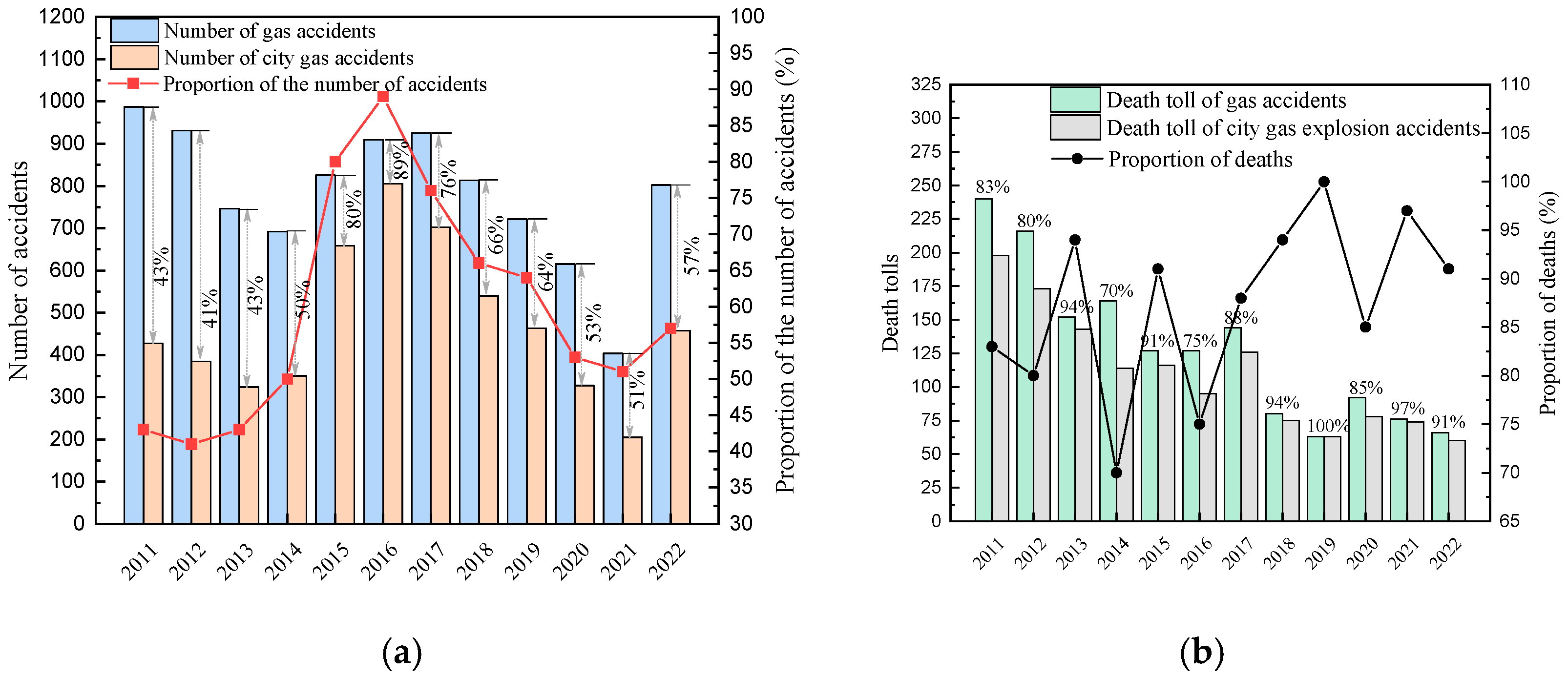
:1. Introduction
2. Methodology
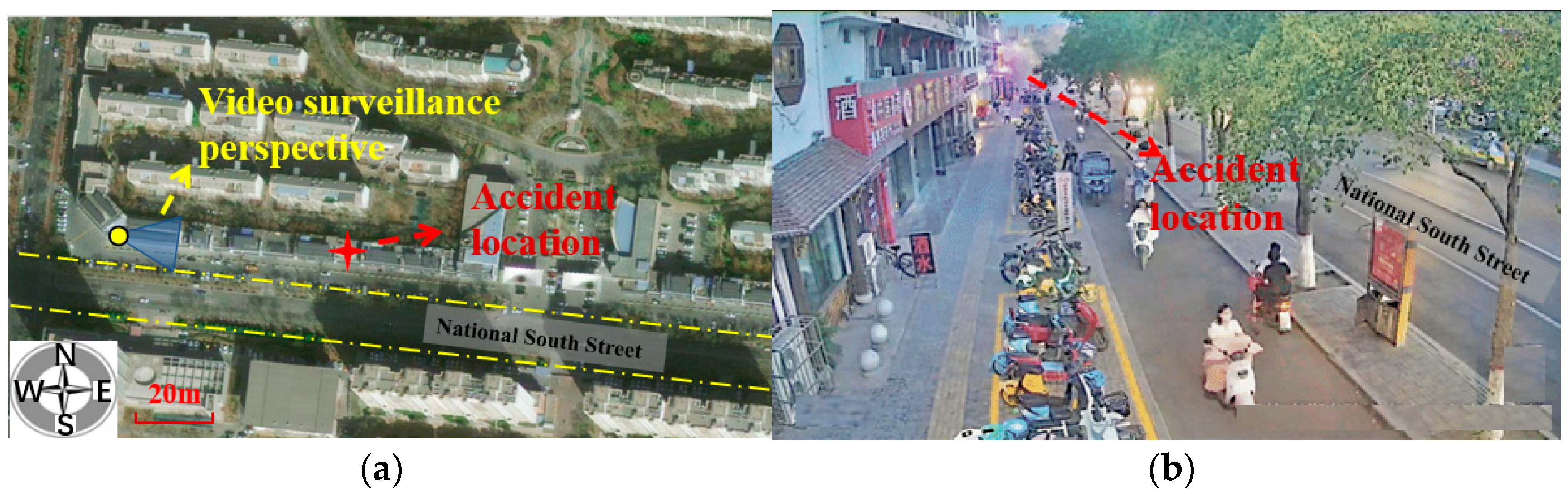
2.1. Accident Consequences and Casualties
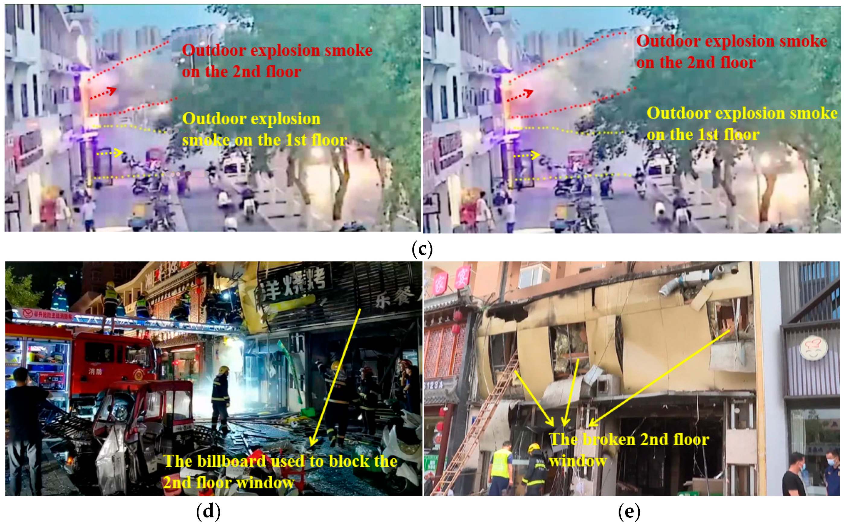
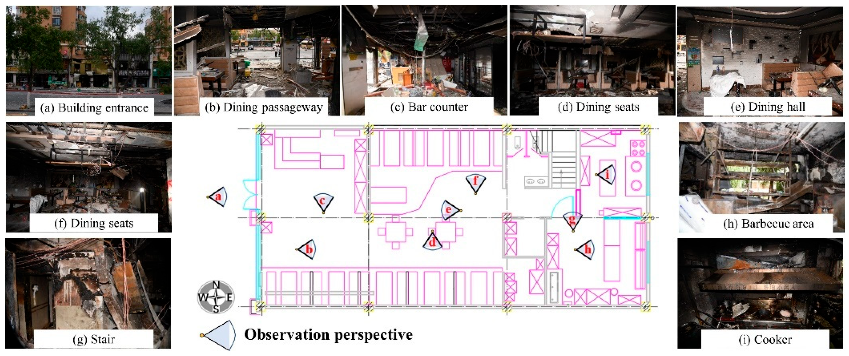
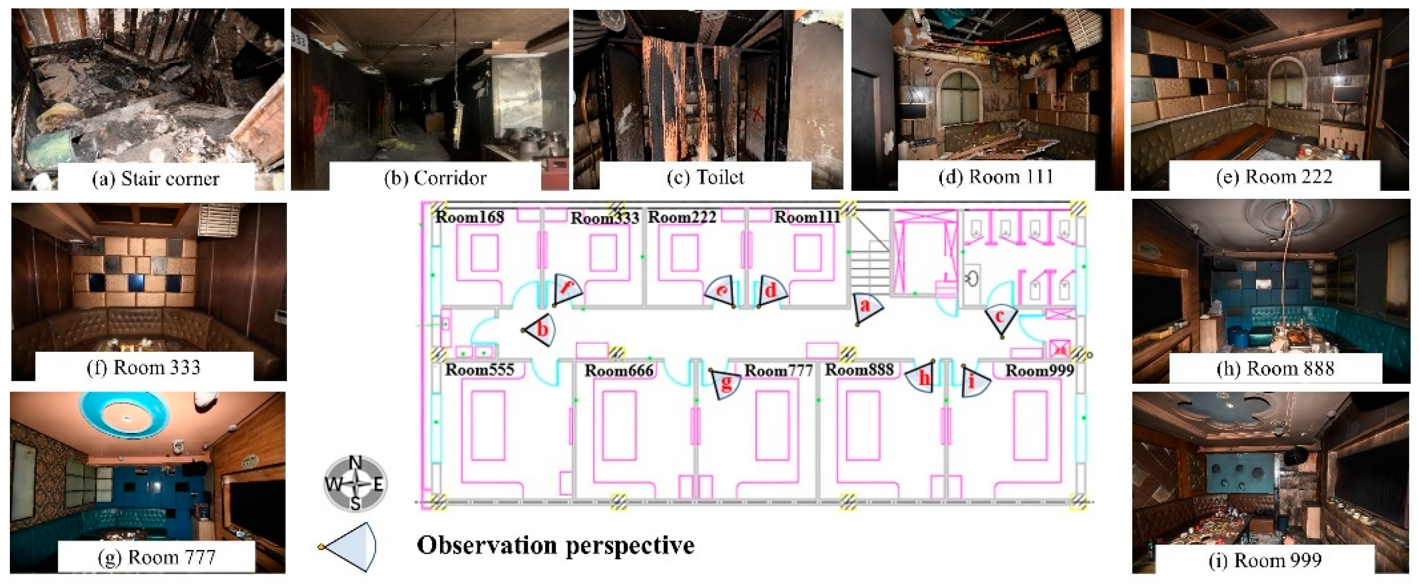
2.1.1. Accident Damage Consequences
2.1.2. Statistics of the Number of Deaths at the Scene
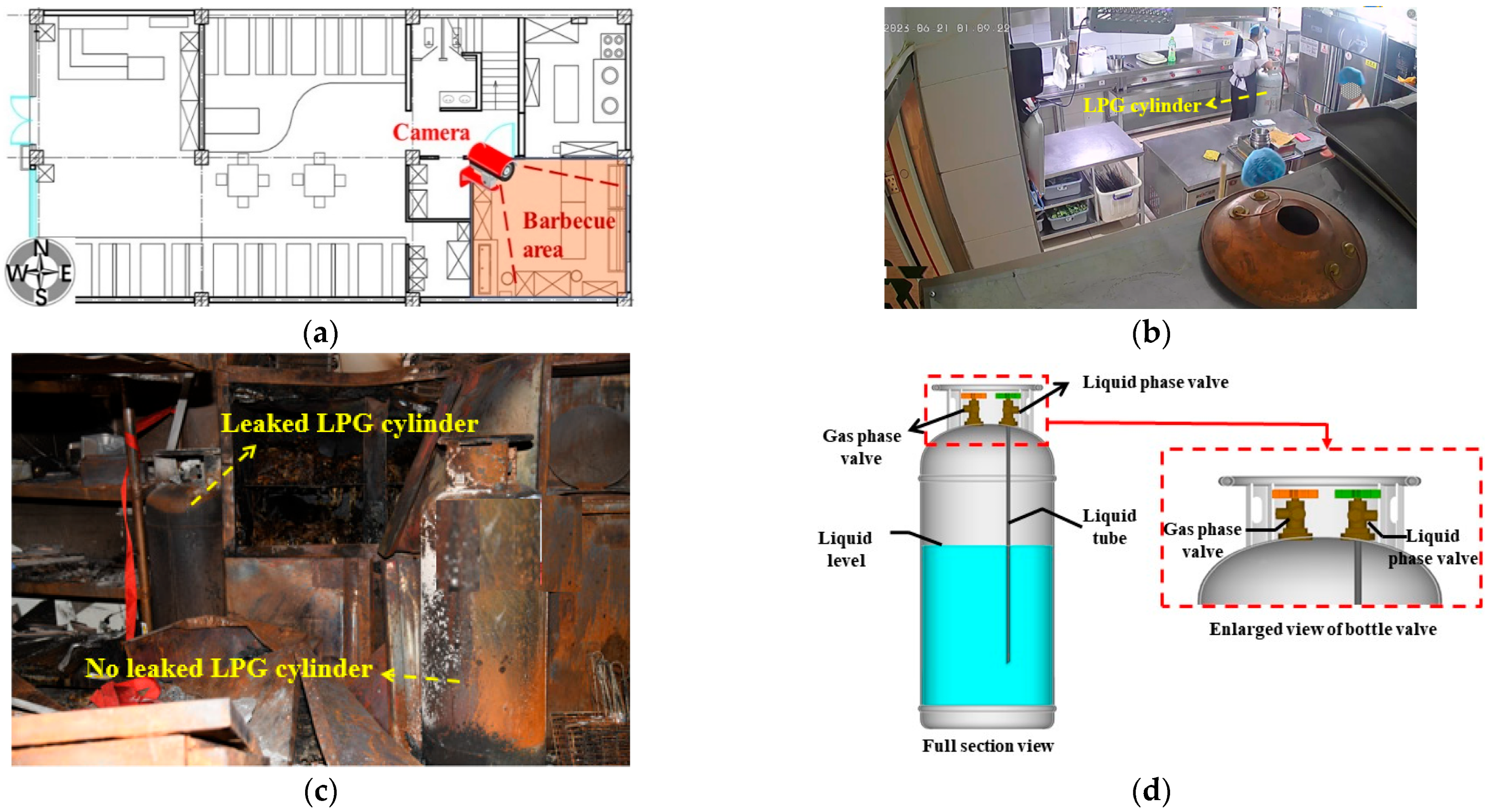
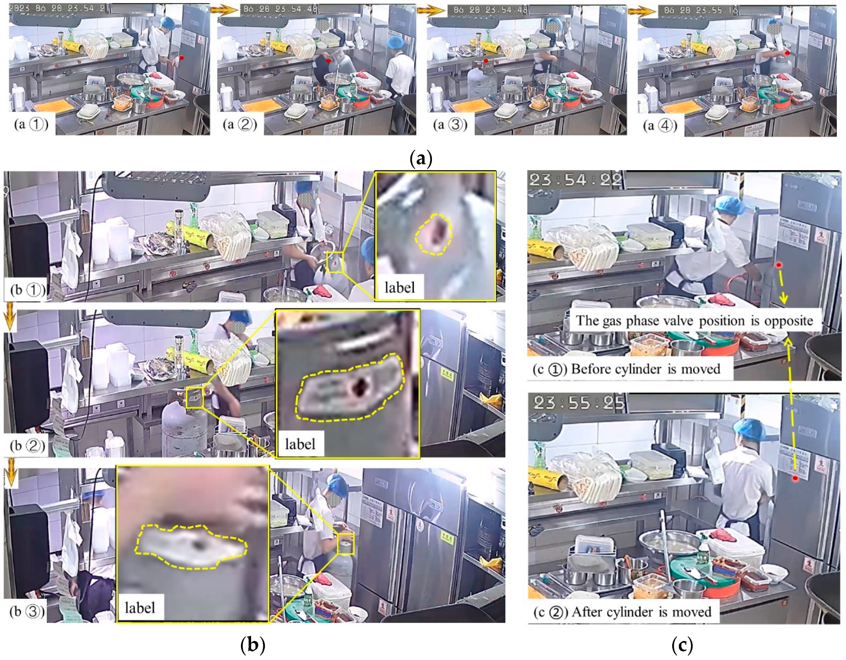
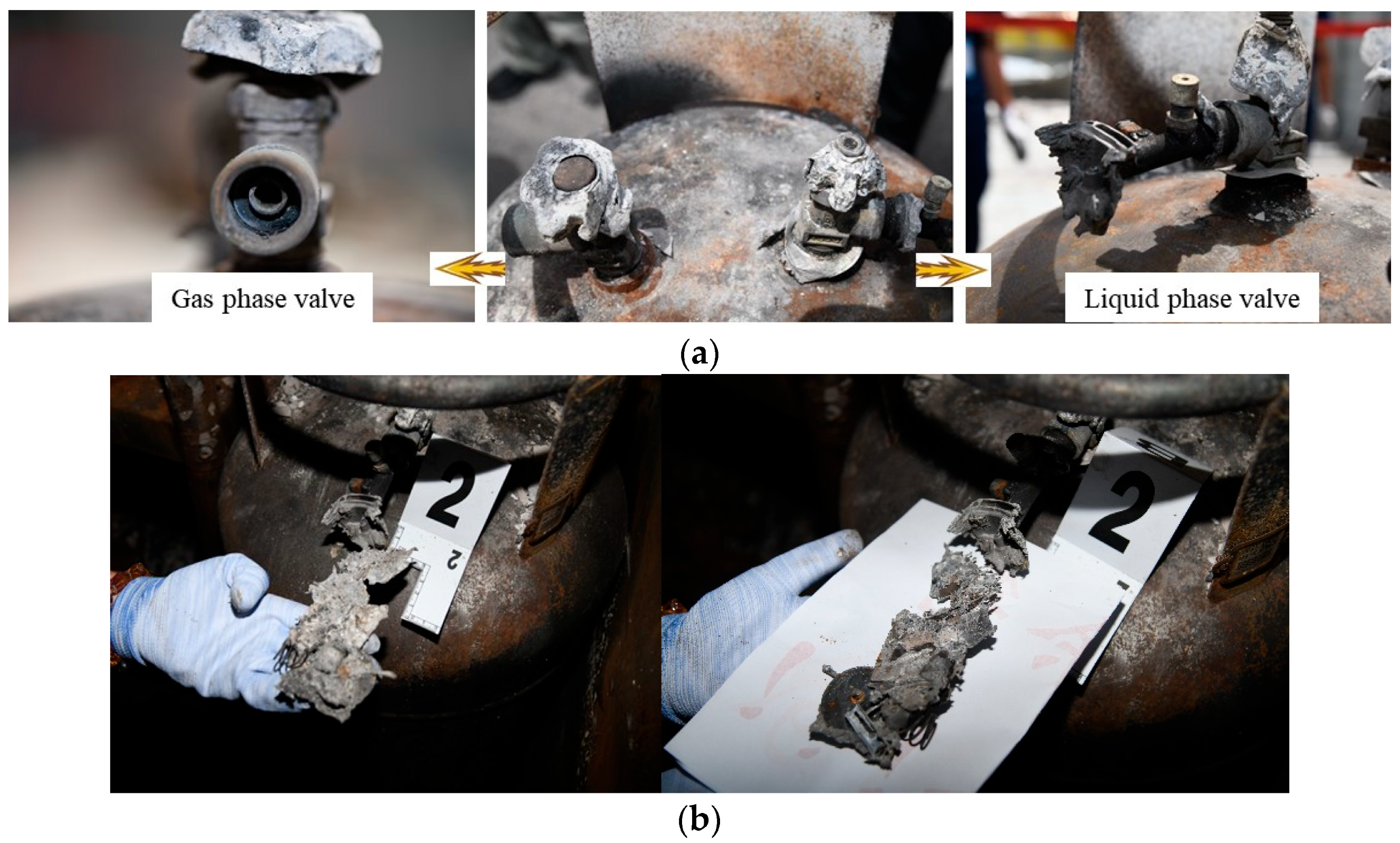
2.1.3. Fuel Leakage Caused by Human Error
2.1.4. Accidental Ignition of Gas Stoves
2.2. Explosion Modeling
2.2.1. Physical Model and Initial Condition
2.2.2. Pressure Relief Boundary
2.2.3. Fuel Filling Settings
3. Results
3.1. Evolution of Explosion Accident Consequences
3.2. Explosion Consequences at Key Locations
4. Discussion of the Accident Cause and Prevention Suggestions
5. Conclusions
- (1)
- The causes of the accident were summarized as follows: The gas company illegally distributed double-valve liquefied petroleum gas cylinders with a gas phase valve and a liquid phase valve to the restaurant involved in the accident. A clerk mistakenly connected the gas phase valve regulator to the liquid phase valve. Upon discovering the error, the regulator was disassembled and reinstalled without proper authorization, leading to the leakage of LPG. Subsequently, the valve was mistakenly opened during disposal, resulting in a significant gas leak. The leaked gas mixed with air, reaching the explosion limit, and ignited from the open flame of the cooking area in the kitchen, causing the explosion. As the only stairway was severely blocked by the collapsed wall and the second-floor windows were also blocked, the escape of people was seriously impeded, resulting in an increase in casualties.
- (2)
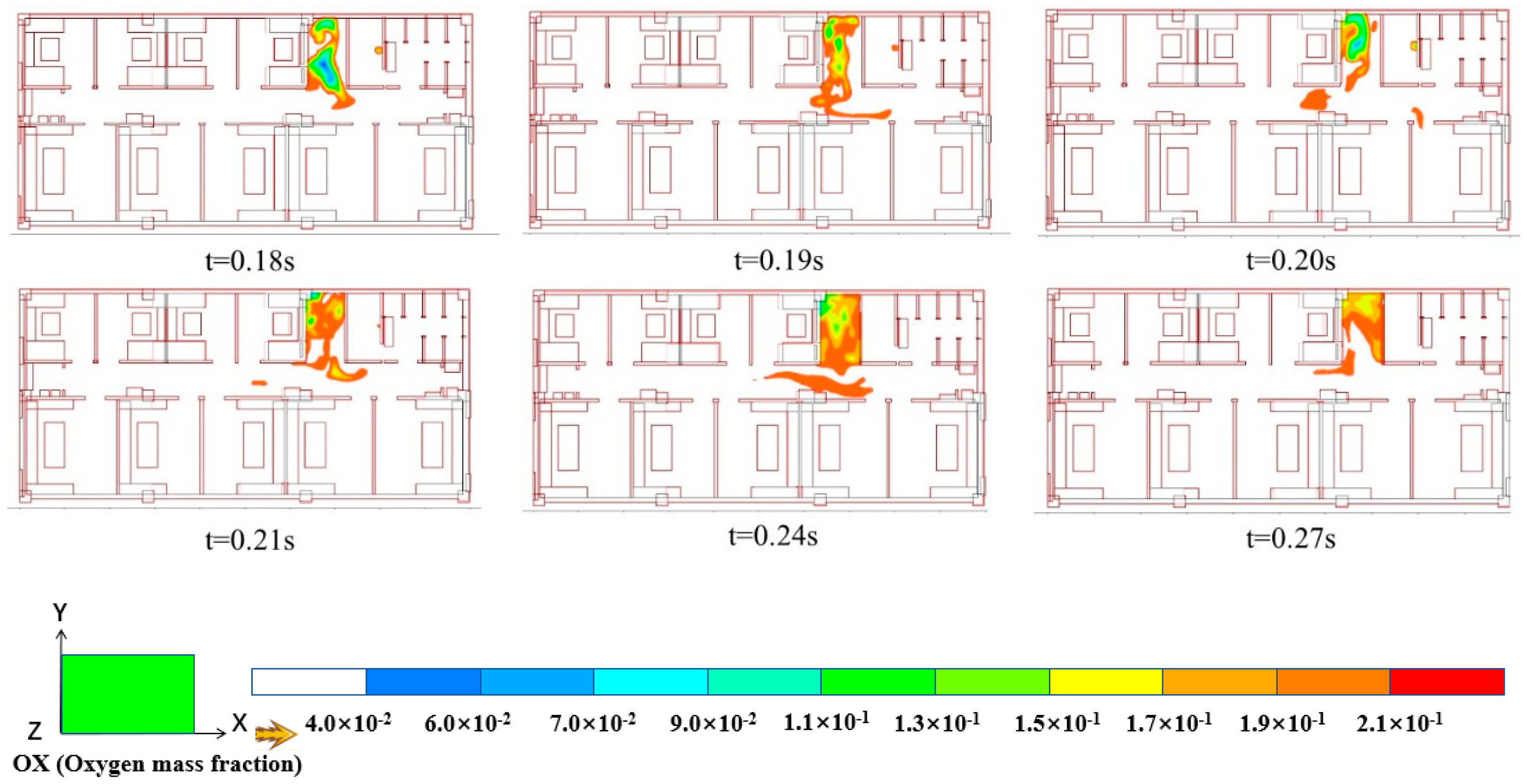
- The maximum explosion overpressure in the building was observed in the barbecue area of the kitchen. The overpressure and temperature levels experienced by the three individuals on the first floor exceeded 70 kPa and 1700 K, respectively, indicating the potential for severe shock-wave injuries and burns. On the second floor, the maximum explosion overpressure in the corridor and Room 111 was measured at 41 kPa and 39.2 kPa, respectively, resulting in moderate damage to the personnel in those areas. In contrast, the overpressure in other rooms only caused slight damage to the personnel. The oxygen content (volume fraction) in a small section of the corridor decreased from 21% to 16%, posing a risk of asphyxiation due to the reduced oxygen levels.
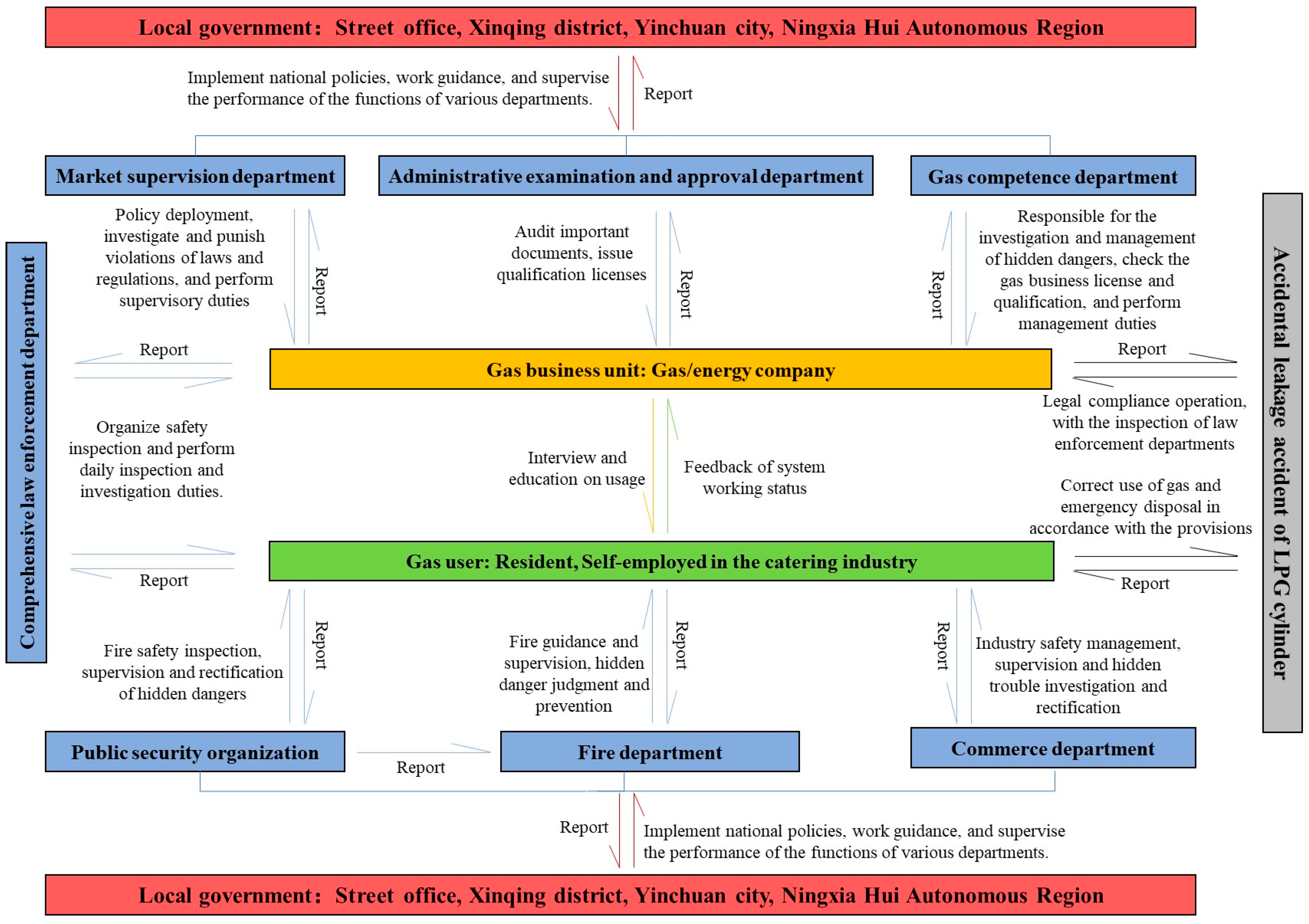
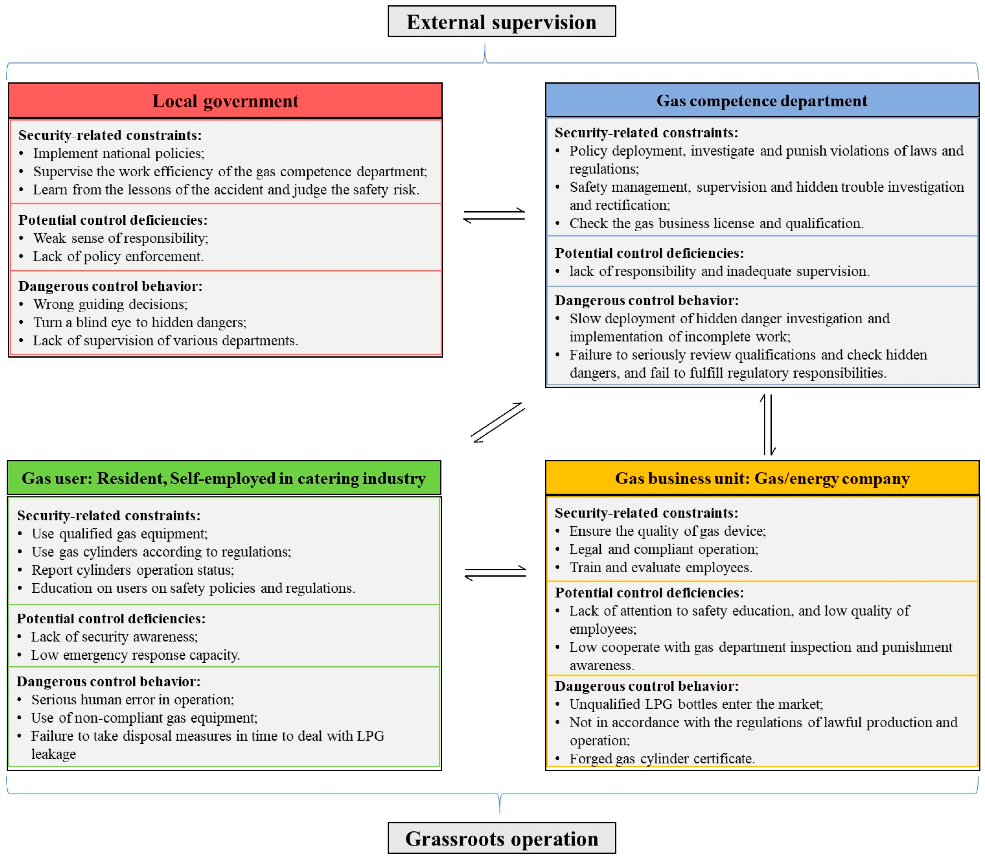
- (3)
- Using the STAMP, the main responsibilities of the four control levels—local government, gas management department, gas companies, and users—were clearly defined. As a part of external supervision, the local government and the gas management department should monitor the department’s functions and ensure that the investigation and rectification of potential risks were carried out effectively. Gas companies and users at the grassroots level should operate and use gas in compliance with regulations, and in the event of a leak, they should promptly and correctly address the issue. The accident was a result of a series of risk control behaviors that significantly deviated from the safety constraints that should have been enforced by each control level. This deviation ultimately led to the tragic incident.
Author Contributions
Funding
Institutional Review Board Statement
Informed Consent Statement
Data Availability Statement
Conflicts of Interest
References
- Meng, X.; Liu, Q.; Luo, X.; Zhou, X. Risk assessment of the unsafe behaviours of humans in fatal gas explosion accidents in China’s underground coal mines. J. Clean. Prod. 2019, 210, 970–976. [Google Scholar] [CrossRef]
- Zhou, G.; Kong, Y.; Yu, J.; Zhang, Q.; Li, R.; Wang, D.; Fan, T.; Cui, Y.; Li, Z. Experimental study on the flame-dual field overpressure coupling evolution characteristics of LPG/DME blended gas explosion venting. J. Clean. Prod. 2024, 444, 141220. [Google Scholar] [CrossRef]
- Kim, M.Y.; Lee, J.H.; Lee, C.S. Combustion characteristics and NOx emissions of a dimethyl-ether-fueled premixed charge compression ignition engine. Energy Fuels 2008, 22, 4206–4212. [Google Scholar] [CrossRef]
- Planas, E.; Pastor, E.; Casal, J.; Bonilla, J.M. Analysis of the boiling liquid expanding vapor explosion (BLEVE) of a liquefied natural gas road tanker: The Zarzalico accident. J. Loss Prevent. Proc. 2015, 34, 127–138. [Google Scholar] [CrossRef]
- Li, X.; Ma, J. Investigation of urban natural gas pipeline leak and resulting dispersion in a semi-closed space: A case of accident in Shiyan, China. Process Saf. Environ. 2024, 183, 459–475. [Google Scholar] [CrossRef]
- Pang, L.; Li, W.; Yang, K.; Meng, L.; Wu, J.; Li, J.; Ma, L.; Chen, S.; Liang, Y. Civil gas energy accidents in China from 2012–2021. J. Saf. Sci. Resil. 2023, 4, 348–357. [Google Scholar] [CrossRef]
- Tian, B.; Zhao, Z.; Cui, X.; Zhu, J. Characteristics of malignant urban gas accidents in China from 2013 to 2022. Heliyon 2024, 10, 34568. [Google Scholar] [CrossRef]
- Cen, K.; Song, B.; Jiao, W.; Yu, W.; Liu, T.; Zhang, H.; Du, J. Quantitative risk assessment of gas leakage and explosion accidents and its security measures in open kitchens. Eng. Fail. Anal. 2021, 130, 105763. [Google Scholar] [CrossRef]
- Mccann, D.P.J.; Thomas, G.O.; Edwards, D.H. Gas dynamics of vented explosions part 1: Experimental studies. Combust. Flame 1985, 59, 233–250. [Google Scholar] [CrossRef]
- Poli, M.; Grätz, R.; Schröder, V. An experimental study on safety-relevant parameters of turbulent gas explosion venting at elevated initial pressure. Procedia Eng. 2012, 42, 90–99. [Google Scholar] [CrossRef]
- Bao, Q.; Fang, Q.; Zhang, Y.; Chen, L.; Yang, S.; Li, Z. Effects of gas concentration and venting pressure on overpressure transients during vented explosion of methane-air mixtures. Fuel 2016, 175, 40–48. [Google Scholar] [CrossRef]
- Bauwens, C.R.; Chao, J.; Dorofeev, S.B. Effect of hydrogen concentration on vented explosion overpressures from lean hydrogen-air deflagrations. Int. J. Hydrogen Energy 2012, 37, 17599–17605. [Google Scholar] [CrossRef]
- Carcassi, M.N.; Fineschi, F. Deflagrations of H2-air and CH4-air lean mixtures in a vented multi-compartment environment. Energy 2005, 30, 1439–1451. [Google Scholar] [CrossRef]
- Chow, S.K.; Cleaver, R.P.; Fairweather, M.; Walker, D.G. An experimental study of vented explosions in a 3:1 aspect ratio cylindrical vessel. Process Saf. Environ. 2000, 78, 425–433. [Google Scholar] [CrossRef]
- Di Sarli, V.; Di Benedetto, A.; Russo, G. Sub-grid scale combustion models for large eddy simulation of unsteady premixed flame propagation around obstacles. J. Hazard. Mater. 2010, 180, 71–78. [Google Scholar] [CrossRef]
- Diakow, P.A.; Thomas, J.K.; Vivanco, E. Comparison of large-scale vented deflagration tests to CFD simulations for partially congested enclosures. J. Loss Prevent. Proc. 2018, 56, 147–154. [Google Scholar] [CrossRef]
- Ding, Y.; Yu, D. Estimation of failure probability of oil and gas transmission pipelines by fuzzy fault tree analysis. J. Loss Prevent. Proc. 2005, 18, 83–88. [Google Scholar]
- Aalirezaei, A.; Kabir, G.; Khan, M.S.A. Dynamic predictive analysis of the consequences of gas pipeline failures using a Bayesian network. Int. J. Crit. Infr. Prot. 2023, 43, 100638. [Google Scholar]
- Zhou, G.; Kong, Y.; Zhang, Q.; Li, R.; Qian, X.; Zhao, H.; Ding, J.; Li, Y.; Yang, S.; Liu, Y. Effect of dimensionless vent ratio on the flame-shock wave evolution dynamics of blended LPG/DME gas explosion venting. Fuel 2024, 358, 130205. [Google Scholar]
- Stein, J.E.; Heiss, K. The Swiss cheese model of adverse event occurrence—Closing the holes. Semin. Pediatr. Surg. 2015, 24, 278–282. [Google Scholar]
- Hansen, O.R.; Gavelli, F.; Ichard, M.; Davis, S.G. Validation of FLACS against experimental data sets from the model evaluation database for LNG vapor dispersion. J. Loss Prevent. Proc. 2010, 23, 857–877. [Google Scholar] [CrossRef]
- Hansen, O.R.; Johnson, D.M. Improved far-field blast predictions from fast deflagrations, DDTs and detonations of vapour clouds using FLACS CFD. J. Loss Prevent. Proc. 2015, 35, 293–306. [Google Scholar] [CrossRef]
- Hu, Q.; Shen, X.; Huang, Z.; Qian, X.; Jiang, J.; Yuan, M.; Pang, L. Shock wave dynamics and venting overpressure hazards induced by indoor premixed hydrogen/air explosion. Int. J. Hydrogen Energy 2014, 51, 830–847. [Google Scholar] [CrossRef]
- Zhang, Q.; Qian, X.; Li, R.; Zhou, G.; Sun, L.; Ma, Y.; Kong, Y. Explosion characteristics and chemical kinetics of blended LPG/DME clean fuel based on pyrolysis and oxidation mechanism model. Fuel 2022, 320, 123896. [Google Scholar] [CrossRef]
- Gong, Y.; Li, Y. STAMP-based causal analysis of China-Donghuang oil transportation pipeline leakage and explosion accident. J. Loss Prevent. Proc. 2018, 56, 402–413. [Google Scholar] [CrossRef]
- Zhang, Y.; Dong, C.; Guo, W.; Dai, J.; Zhao, Z. Systems theoretic accident model and process (STAMP): A literature review. Saf. Sci. 2022, 152, 105596. [Google Scholar] [CrossRef]
- Patriarca, R.; Chatzimichailidou, M.; Karanikas, N.; Di Gravio, G. The past and present of System-Theoretic Accident Model and Processes (STAMP) and its associated techniques: A scoping review. Saf. Sci. 2022, 146, 105566. [Google Scholar] [CrossRef]


| Time | Accident Province | Accident Description and Cause | Accident Consequence |
|---|---|---|---|
| 21 June 2023 | Yinchuan City, Ningxia Hui Autonomous Region | Incorrect operation caused gas leakage in the tank, resulting in an explosion when encountering an open flame. | 31 people died, and 7 people were injured. |
| 28 September 2022 | Changchun City, Jilin Province | Welding sparks caused methanol–air vapor deflagration, and a large amount of liquid methanol flowed onto the ground and caught fire. | 17 people died, and 3 people were injured. |
| 13 June 2021 | Shiyan City, Hubei Province | A gas pipeline was corroded and ruptured, and the leaked gas was ignited and exploded by the spark discharged by the exhaust fume pipeline. | 26 people died, and 138 people were injured. |
| 13 June 2020 | Wenling City, Zhejiang Province | After a tank was torn and disintegrated, gas rapidly ejected, vaporized, diffused, and exploded in the presence of sparks generated by vehicles. | 20 people died, and 175 people were injured. |
| 10 October 2015 | Wuhu City, Anhui Province | Improper operation caused the angle valve to fall off, and a large amount of gas was ejected and exploded after exposure to open fire. | 17 people died. |
| 11 June 2013 | Suzhou City, Jiangsu Province | A gas pipeline was not cut off, causing leakage, and an electrical spark caused an explosion. | 12 people died, and 8 people were injured. |
| 23 November 2012 | Jinzhong City, Shanxi Province | The corner valve of a cylinder was not closed, which led to gas leakage and an explosion in the case of a relay spark. | 14 people died, and 47 people were injured. |
| 14 November 2011 | Xian City, Shaanxi Province | Bottled gas leaked due to incomplete closure of the liquid phase valve. | 11 people died, and 31 people were injured. |
| Pressure Relief Plate | Opening Pressure (kPa) | Area (m2) | Area Mass (kg/m2) |
|---|---|---|---|
| Glass door on the 1st floor | 15 | 8.38 | 12.5 |
| Glass wall on the 1st floor | 15 | 13.4 | 12.5 |
| West wall of the cooking area | 70 | 15.41 | 252 |
| East wall of the barbecue area | 55 | 7.27 | 168 |
| Doors of all rooms on the 2nd floor | 3 | 3.1 | 30 |
| Location | Overpressure (kPa) | Temperature (K) | Description of Explosion Consequences |
|---|---|---|---|
| Cooking area | 80.5 | 1996 | Personnel: Severe shock-wave injury, severe burns. |
| Building: Complete destruction (Level 7). The adjacent walls of the stairs collapsed, and the north wall was seriously displaced. | |||
| Barbecue area | 92.0 | 2077 | Personnel: Severe shock-wave injury, severe burns. |
| Building: Complete destruction (Level 7). The east wall collapsed. | |||
| Toilet doorway | 70.8 | 1927 | Personnel: Severe shock-wave injury, severe burns. |
| Building: Serious damage (Level 6). | |||
| Store room | 67.4 | 1677 | Personnel: Severe shock-wave injury, severe burns. |
| Building: Serious damage (Level 6). The self-built non-load-bearing wall collapsed. | |||
| Dining hall | 32.0 | 220 | Personnel: Mild injury, may be damaged by debris. |
| Building: Moderate damage (Level 4). Wooden doors and windows were extensively damaged. | |||
| Restaurant entrance | 21.6 | 102 | Personnel: Mild injury, may be damaged by debris. |
| Building: Mild damage (Level 3). Glass shattered and debris flew out. |
| Location | Overpressure (kPa) | Temperature (K) | Description of Explosion Consequences |
|---|---|---|---|
| Stair | 78.0 | 1766 | Personnel: Severe shock-wave injury, severe burns. |
| Building: Serious damage (Level 6). The east wall of the stairs collapsed and the north wall moved. | |||
| Corridor | 41.0 | 1007 | Personnel: Moderate shock-wave injury, burns. |
| Building: Moderate damage (Level 4). Wall decorations were broken. | |||
| Room 111 | 39.2 | 580~880 | Personnel: Moderate shock-wave injury, minor burns. |
| Building: Moderate damage (Level 4). Wooden ceiling and decorations fell. | |||
| Other rooms | 20.0 | 350~400 | Personnel: Mild injury. |
| Building: Mild damage (Level 3). A small number of decorative pieces fell. | |||
| Toilet | 42.0 | 357 | Personnel: Moderate shock-wave injury. |
| Building: Moderate damage (Level 4). |
Disclaimer/Publisher’s Note: The statements, opinions and data contained in all publications are solely those of the individual author(s) and contributor(s) and not of MDPI and/or the editor(s). MDPI and/or the editor(s) disclaim responsibility for any injury to people or property resulting from any ideas, methods, instructions or products referred to in the content. |
© 2024 by the authors. Licensee MDPI, Basel, Switzerland. This article is an open access article distributed under the terms and conditions of the Creative Commons Attribution (CC BY) license (https://creativecommons.org/licenses/by/4.0/).
Share and Cite
Hu, Q.; Zhang, R.; Qian, X.; Yuan, M.; Li, P. Explosion Shock Dynamics and Hazards in Complex Civil Buildings: A Case Study of a Severe Fuel Explosion Accident in Yinchuan, China. Fire 2024, 7, 310. https://doi.org/10.3390/fire7090310
Hu Q, Zhang R, Qian X, Yuan M, Li P. Explosion Shock Dynamics and Hazards in Complex Civil Buildings: A Case Study of a Severe Fuel Explosion Accident in Yinchuan, China. Fire. 2024; 7(9):310. https://doi.org/10.3390/fire7090310
Chicago/Turabian StyleHu, Qianran, Ruoheng Zhang, Xinming Qian, Mengqi Yuan, and Pengliang Li. 2024. "Explosion Shock Dynamics and Hazards in Complex Civil Buildings: A Case Study of a Severe Fuel Explosion Accident in Yinchuan, China" Fire 7, no. 9: 310. https://doi.org/10.3390/fire7090310