


Intelligent Fire Suppression Devices Based on Microcapsules Linked to Sensor Internet of Things

Abstract
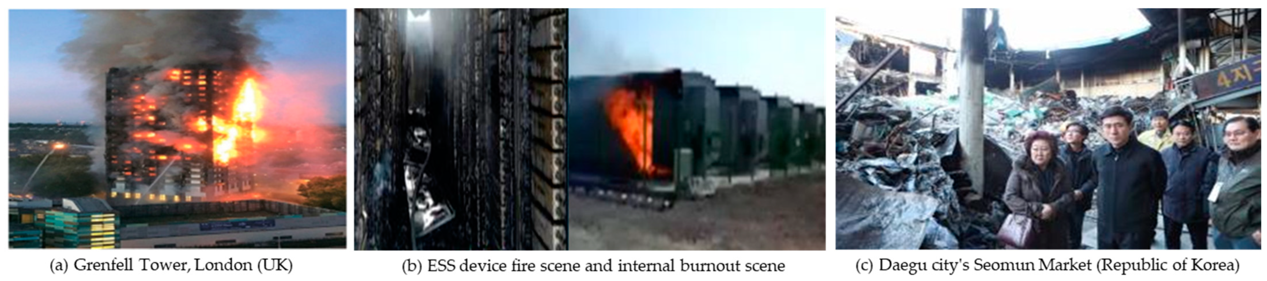
:1. Introduction
2. Implementation of IoT-Based Intelligent Microcapsule Composite Device
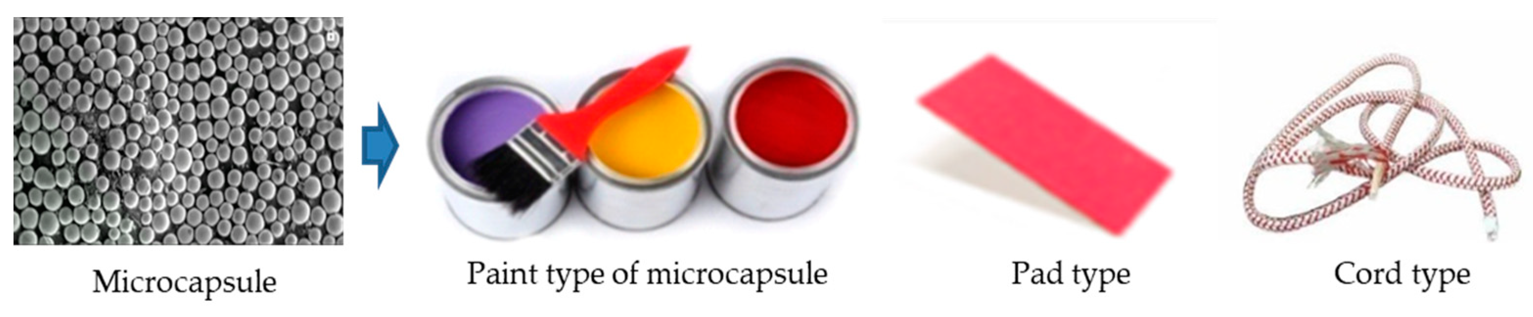
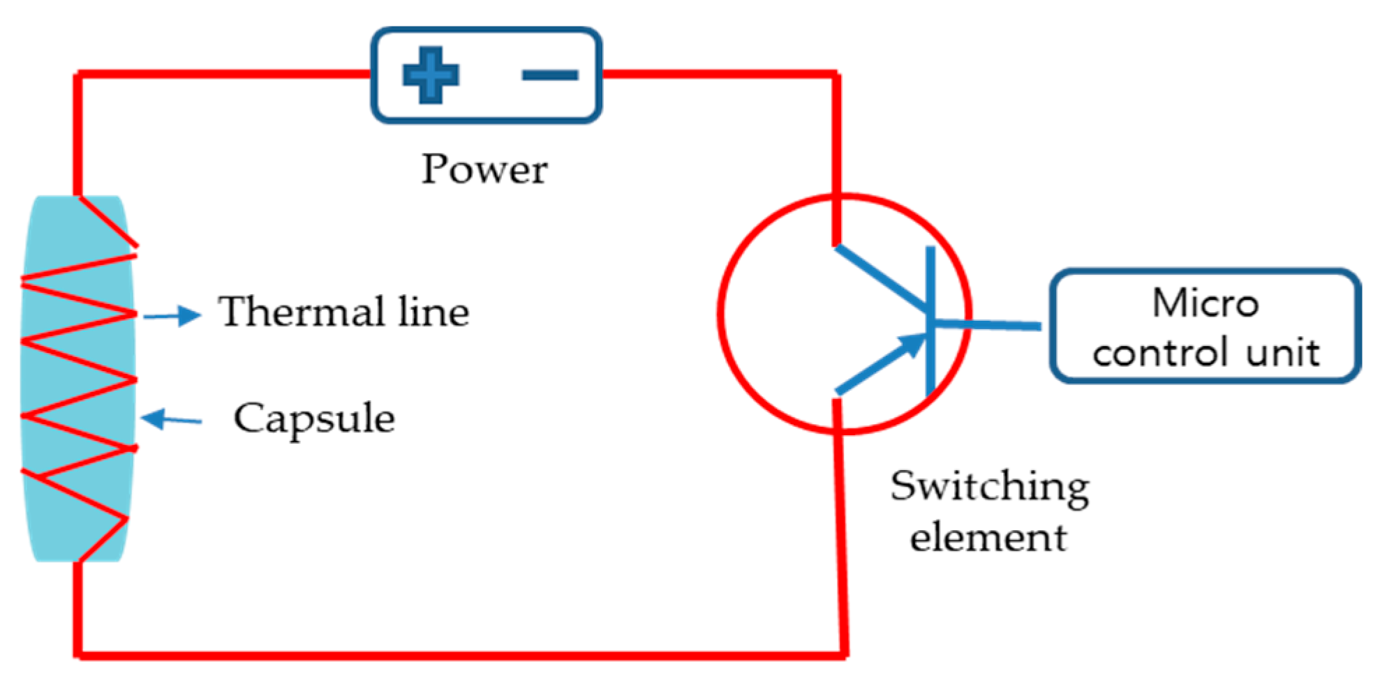
2.1. Microcapsule Composite Material
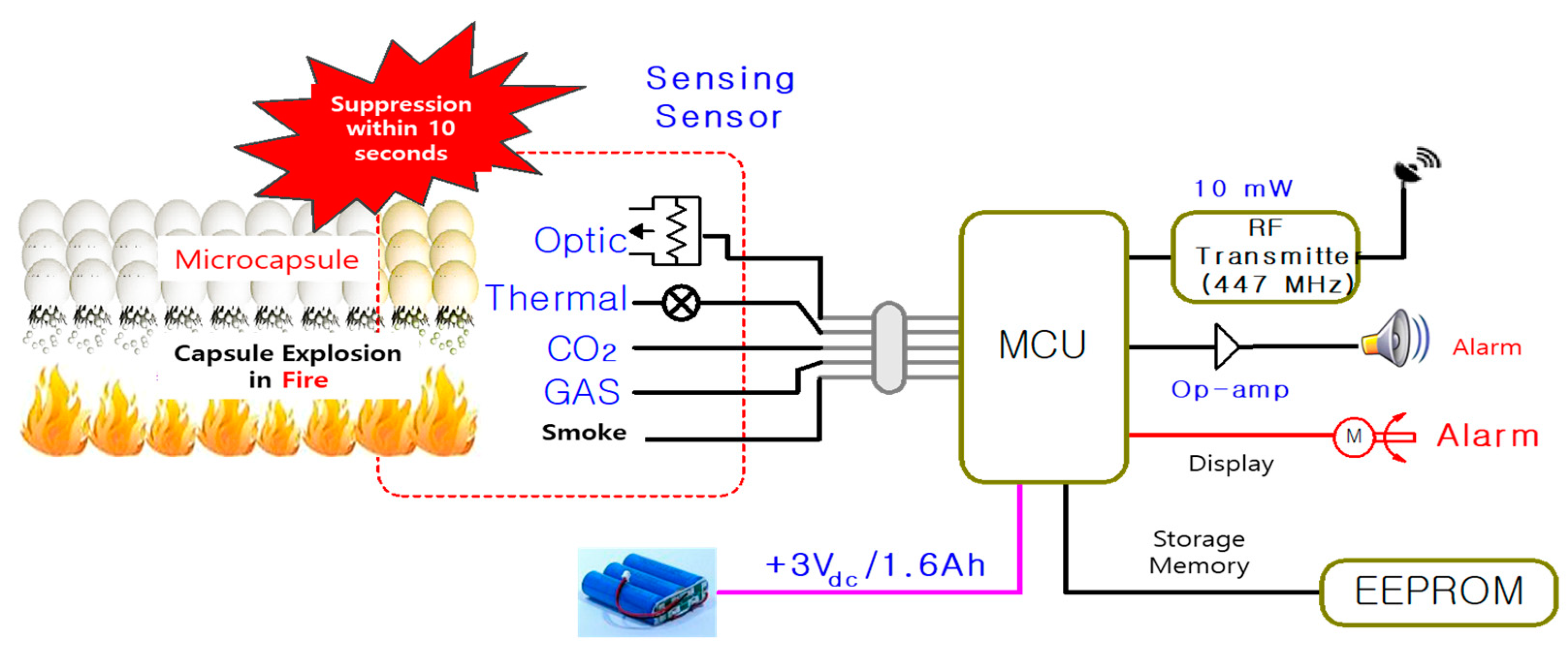
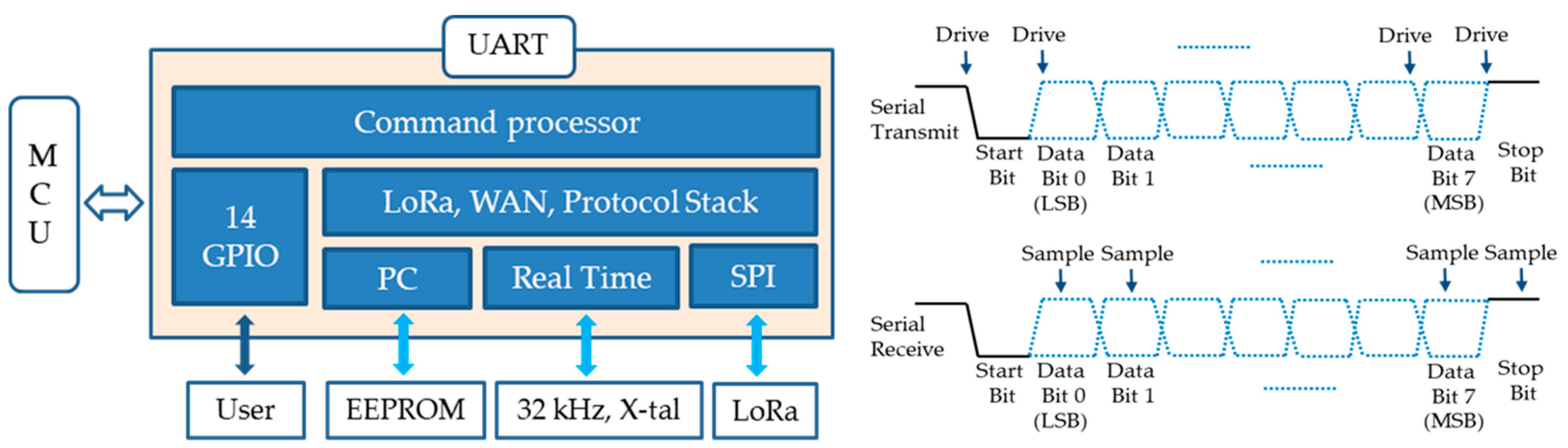
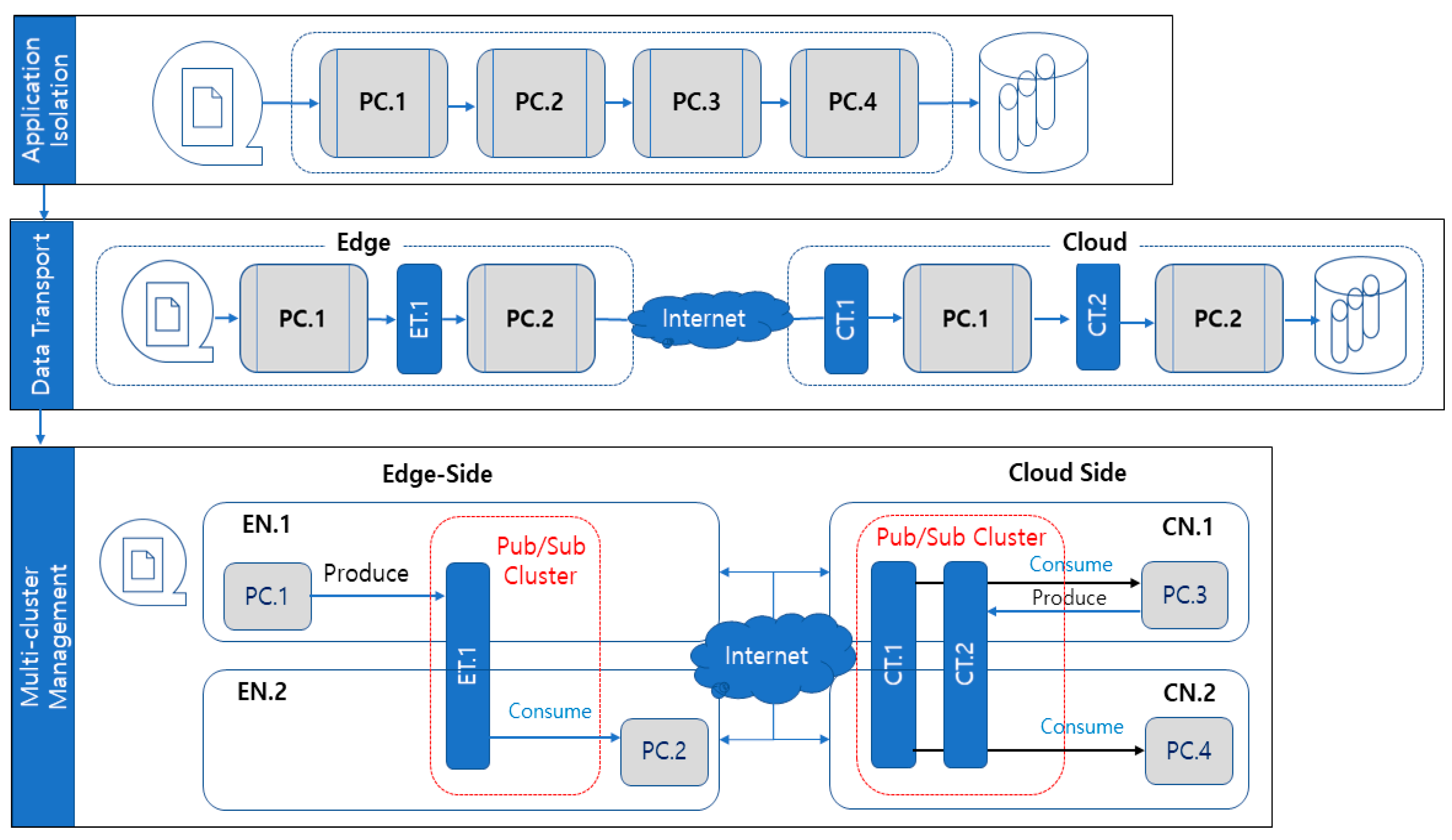
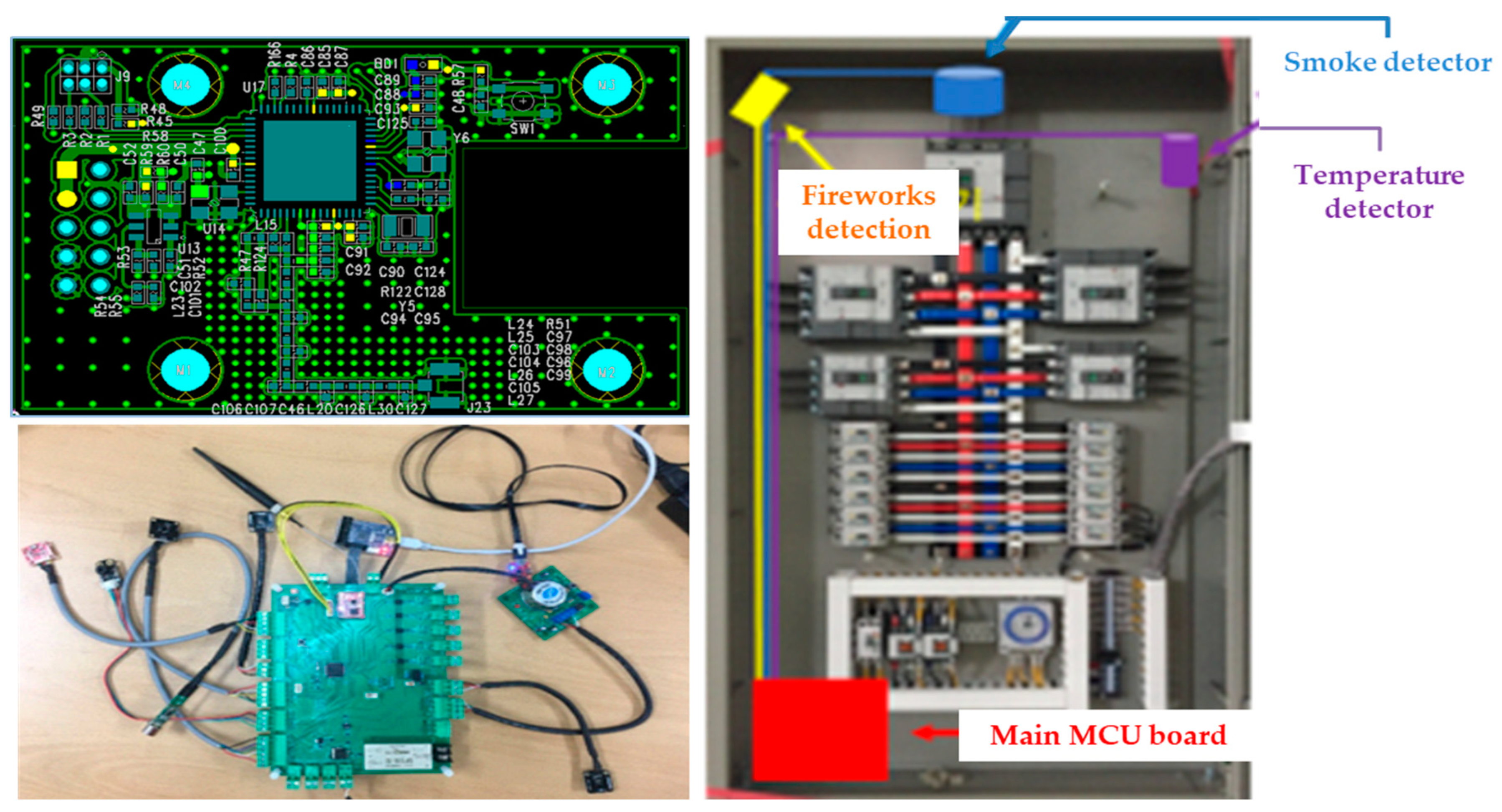
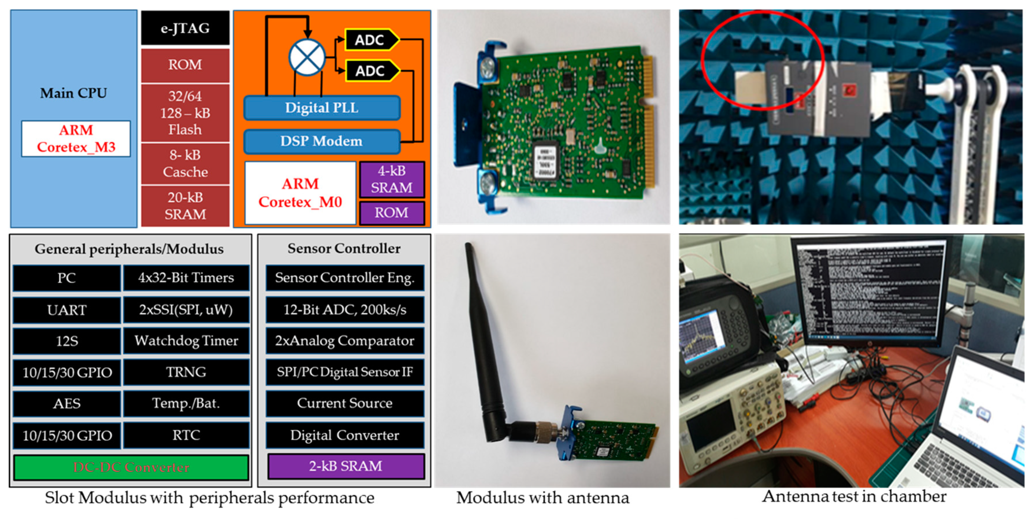
2.2. Sensor IoT Architecture and Gateway Communication Configuration
3. Experimental Results
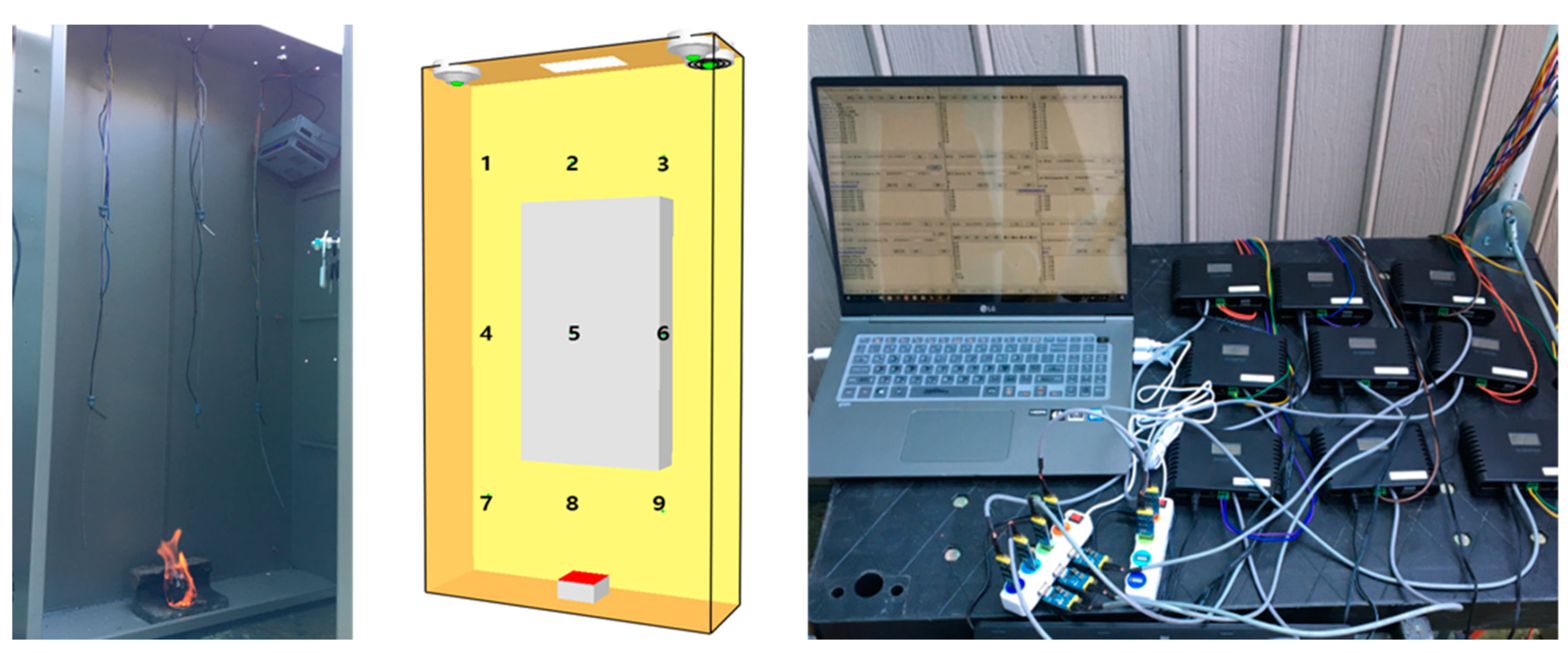
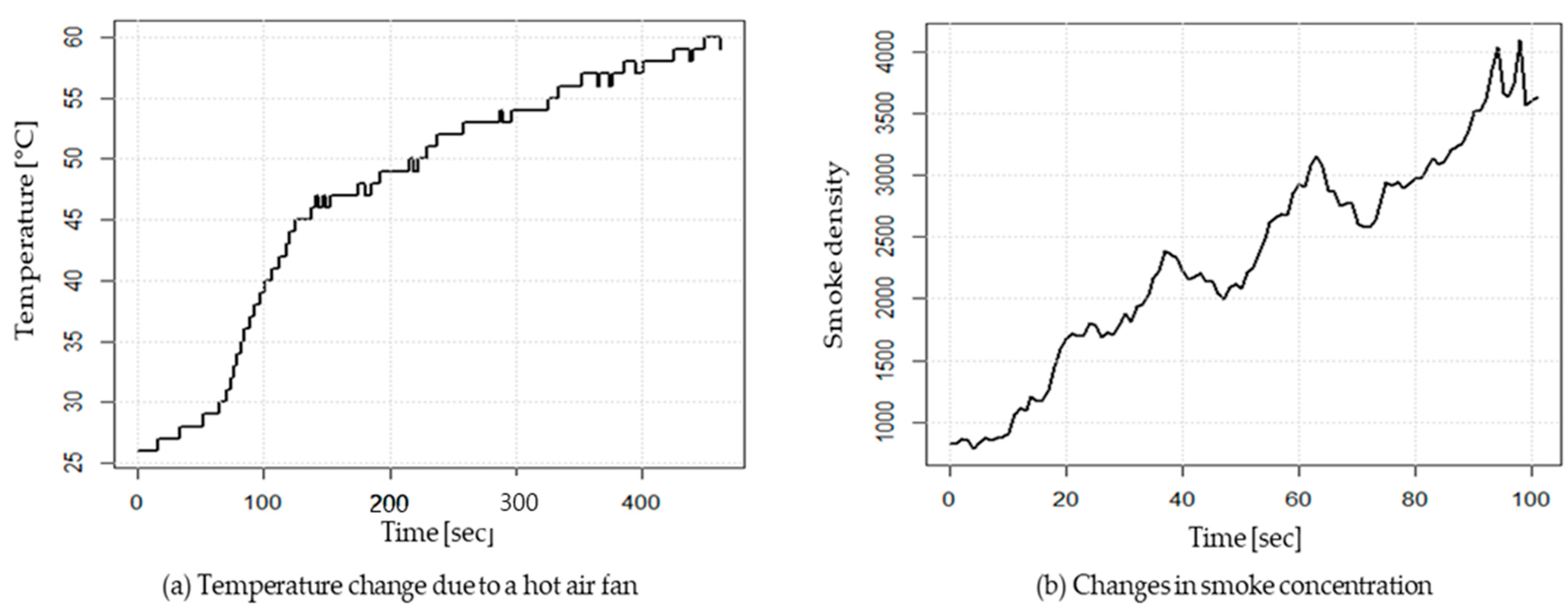
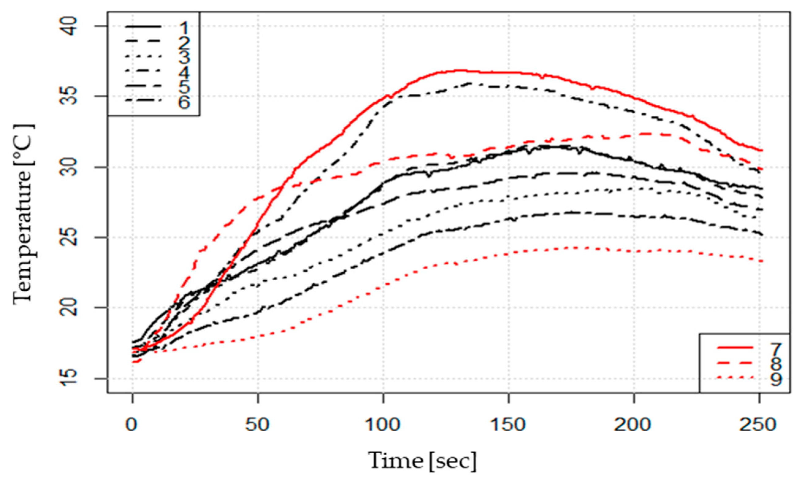
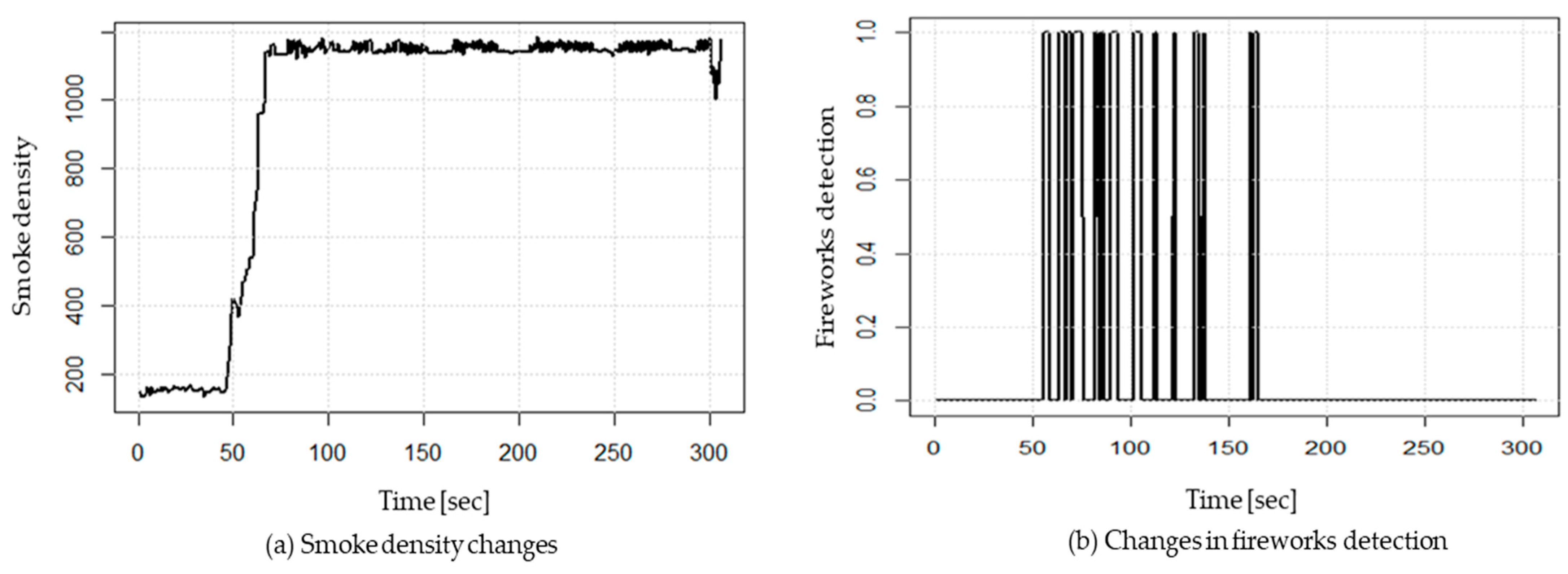
3.1. Smoke and Heat Sensing Performance Experiments
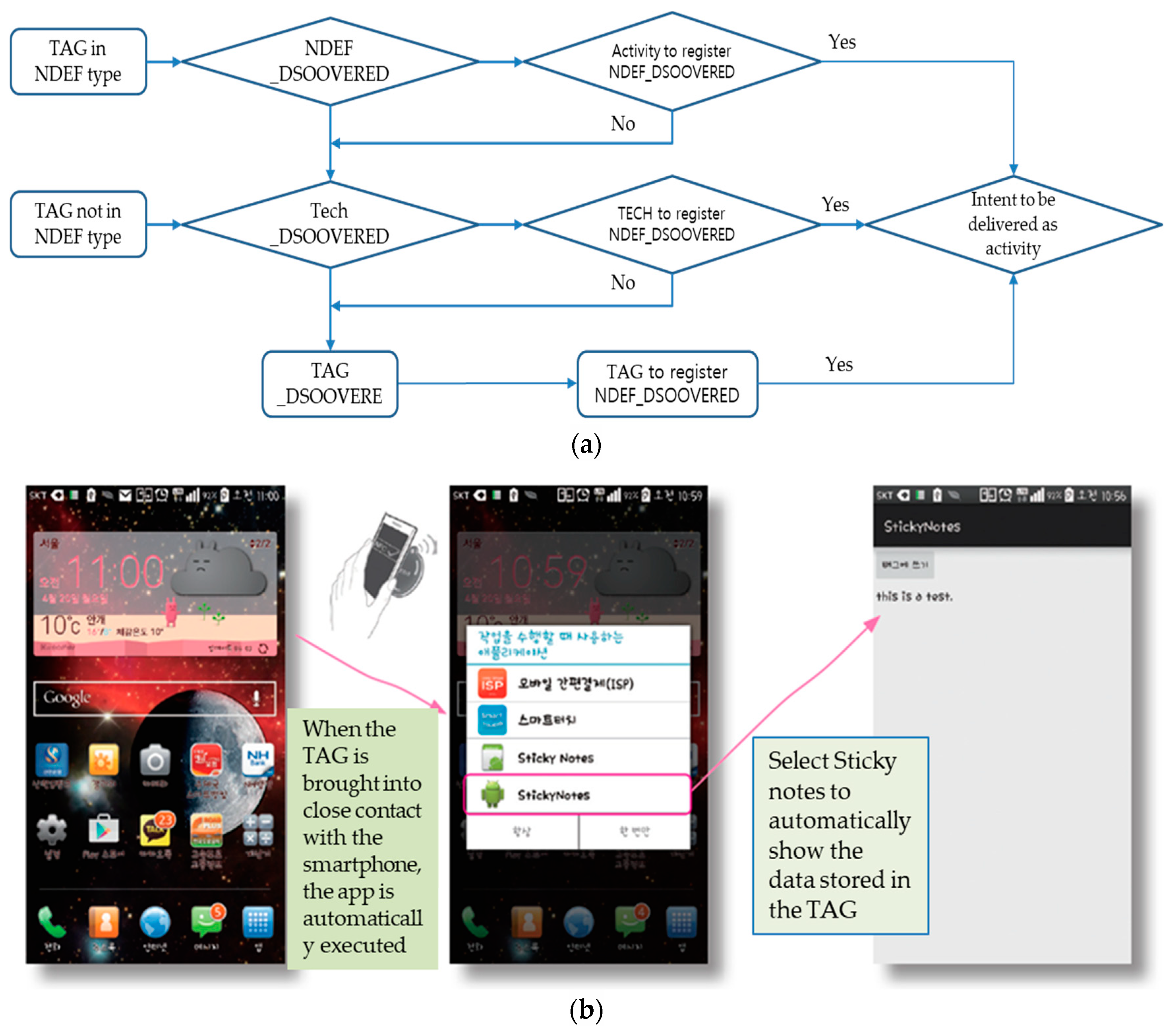
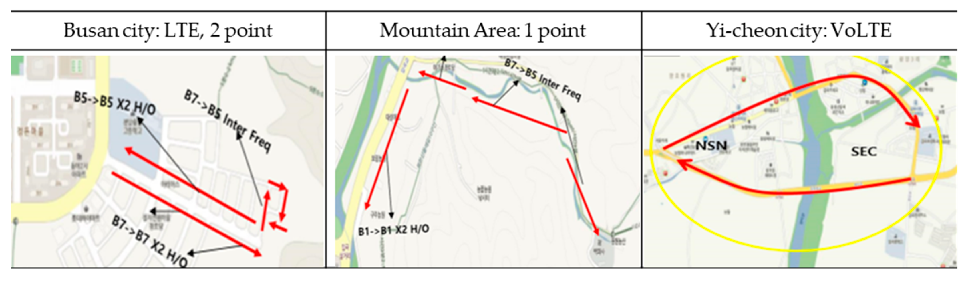
3.2. Mobile Performance Evaluation by Sensor Behavior
4. Conclusions
Author Contributions
Funding
Institutional Review Board Statement
Informed Consent Statement
Data Availability Statement
Conflicts of Interest
References
- National Fire Information System, Gyeonggi Disaster and Safety Headquarters National Fire System Analysis Data; Kyeonggi-Do Fire Services: Republic of Korea, 2016.
- Yoon, D.H.; Kim, S.H.; Yoon, J.H. Intellectual Fire Extinguisher using Micro Capsules based on IoT. Korean J. Saf. Cult. 2022, 15, 111–124. [Google Scholar] [CrossRef]
- Alkhatib, A. Review on Forest Fire Detection Techniques. Int. J. Distrib. Sens. Netw. 2014, 2014, 597368. [Google Scholar] [CrossRef]
- Udaya, D.; Lumini, B.; Ridma, W.; Kishanga, K.; Bathiya, J. Forest fire detection system using wireless sensor networks and machine learning. Sci. Rep. 2022, 12, 46. [Google Scholar]
- Lee, S.S.; Jeong, C.Y. Composition of Halogen-Based Gas Extinguishing Agent and Method of Manufacturing the Same. Patent 10-1733423, 28 May 2017. [Google Scholar]
- Fire Insurance Association, Webzine. 2018, Volume 84. Available online: https://www.kfpa.or.kr/webzine/201809/sub/disasters1.html (accessed on 7 May 2024).
- Yoon, D.H.; Lee, D.H.; Lee, D.W. Development of IoT Sensing Technology Convergence Intelligent Fire Extinguishing System Using Microcapsule Digestives. In Industrial Complex Corporation R&BD Capacity Building Project; Ecosense Co. Ltd.: Seoul, Republic of Korea, 2020. [Google Scholar]
- Go, B.C. IoT Technology for Forest Fire Disaster Monitoring. Broadcast Media Mag. 2015, 20, 91–98. [Google Scholar]
- Çelik, T. Fast and Efficient Method for Fire Detection using Image Processing. ETRI J. 2010, 32, 881–890. [Google Scholar] [CrossRef]
- Zang, J.; Li, W.; Han, N.; Kan, J. Forest Fire Detection System based on a ZigBee Wireless Sensor Network. Front. For. China 2008, 3, 369–374. [Google Scholar] [CrossRef]
- Kechar, B.; Houache, N.; Larbi, S. Using Wireless Sensor Networks for Reliable Forest Fires Detection. Procedia Comput. Sci. 2013, 19, 794–801. [Google Scholar]
- Evizal, A.K.; Hitoshi, I.; Sri, L.R. Modeling of Wireless Sensor Networks for Detection Land and Forest Fire Hotspot. In Proceedings of the 2019 International Conference on Electronics, Information, and Communication (ICEIC), Auckland, New Zealand, 22–25 January 2019; Volume 1, pp. 1–5. [Google Scholar]
- Zhang, J.; Li, W.; Yin, Z.; Liu, S.; Guo, X. Forest Fire Detection System based on Wireless Sensor Network. In Proceedings of the 2009 4th IEEE Conference on Industrial Electronics and Applications, Xi’an, China, 25–27 May 2009; pp. 520–523. [Google Scholar]
- Kim, J.J.; Kwak, D.K.; Lee, T.J.; Park, D.H.; Kim, J.H. A Study on the Current Status and Problem Analysis of Flame Detectors; A Paper Collection of the Electronics Conference of Electricity. In Proceedings of the KIPE Conference, Hoengseong/Gangwon, Republic of Korea, 4–6 July 2017; pp. 495–496. [Google Scholar]
- Rabinovich, M.; Xiao, Z.; Aggarwal, A. Computing on the Edge: A Platform for Replicating Internet Applications in Web Content Caching and Distribution; Springer: Berlin/Heidelberg, Germany, 2024; pp. 57–77. ISBN 1-4020-2257. [Google Scholar]
- Yoon, J.H.; Yoon, D.H. ECO-KICOX-03-SW Response Speed Self-Performance Evaluation. Ecosense Co. Ltd.: Seoul, Repbulic of Korea, 2020. [Google Scholar]
- Kim, K.H.; Yoo, S.W.; Kim, K.M.; Rim, C.S.; Park, J.S. IEEE 802.15.4-based Ubiquitous Sensor Network Technology. J. Korean Electron. Soc. 2004, 31, 74–84. [Google Scholar]
- Verstockt, S.; Lambert, P.; Van de Walle, R.; Merci, B.; Sette, B. State of the art in vision-based fire and smoke detection. In Proceedings of the 14th International Conference on Automatic Fire Detection, Duisburg, Germany, 8–10 September 2009; University of Duisburg-Essen, Department of Communication Systems: Duisburg, Germany, 2009; Volume 2, pp. 285–292. [Google Scholar]
- Toreyin, B.U.; Dedeoglu, Y.; Cetin, A.E. Flame Detection in Video using Hidden Markov Models. In Proceedings of the IEEE International Conference on Image Processing, Genova, Italy, 14 September 2005; Volume 2, p. II-1230. [Google Scholar]
- Çelik, T.; Ozkaramanlı, H.; Demirel, H. Fire and Smoke Detection Without Sensors: Image Processing-based Approach. In Proceedings of the 2007 15th European Signal Processing Conference, Poznan, Poland, 3–7 September 2007; pp. 1794–1798. [Google Scholar]
- Kim, D.S.; Prak, H.M.; Hwang, T.H.; Won, G.H. Research on the Development of Hardware Location Recognition Engine Using the Maximum Likelihood Method for Location Recognition in IoT Network. J. Korean Electron. Eng. Assoc. 2016, 53, 32–49. [Google Scholar]
- Won, J.S. Electrical Fire (II)—Identification of Causes of Electrical Fire. J. Korean Fire Fire Soc. 1988, 2, 65–70. [Google Scholar]
- Yoon, D.H. Intelligent Type Fire Suppression System and Method Using Internet of Things Sensing Technology Convergence. Patent 10-2230217, 15 March 2021. [Google Scholar]


| Sortation | Pad | Cord | Tube |
|---|---|---|---|
| Material quantity | 2.5~40 g | 25 g | 10 g |
| Protective volume | 3~60 L | 150 L | 2000 L |
| Storage temperature | 50~80 °C | ||
| Activation temperature | 120 °C | 180 °C | 120 °C |
| Test Items | Test Results | Performance Requirements | ||
|---|---|---|---|---|
| Fire detection capability (Sensitivity test) | Temperature | Operation test | 3 s | Operation within 34 s |
| Nonoperatopn test | Inoperative within 10 min | Inoperative within 10 min | ||
| Smoke | Operation test | 9 s | Operation within 30 s | |
| Nonoperatopn test | Inoperative within 5 min | Inoperative within 5 min | ||
| Notice time | Temperature | 3 s | Notification within 20 s | |
| Smoke | 9 s | |||
| Items | Design Specification | Remarks |
|---|---|---|
| Frequency used and Channel | 447.2625~447.5625, 25 h | |
| Physical hierarchy (FHY) | IEEE 802.15.4.4 g | |
| Modulation methods | FSK, 4FSK, MSK, OOK | |
| Chip set | Silicon, Labs, EZR32LG | 32 bit core |
| Maximin Power | 10 dBm below | |
| Maximum reception sensitivity | 133 dBm above |
| Symbol | Minimum | Type | Maximum | Unit |
|---|---|---|---|---|
| VCC | 2.7 | 3.0 | 3.6 | V |
| Leakage current | 0.3 | - | 3.0 | µA |
| Evaluation Items | Evaluation Methods | Experimental Results |
|---|---|---|
| Fire detection capability | Temperature and smoke detection time | Temp.: 3 s, smoke: 9 s. |
| Temperature resistance | Fire-free holding temperature time | −10~50 °C |
| Time to reach the operating temperature of the microcapsule | Fire reaction time of microcapsules after fire breaks out | 4 s or less |
| Wireless test distance | Open field test | More than 500 m |
| Software Response Speed | Measuring the software’s response speed at the same time as fire detection | 1.12 s or less |
Disclaimer/Publisher’s Note: The statements, opinions and data contained in all publications are solely those of the individual author(s) and contributor(s) and not of MDPI and/or the editor(s). MDPI and/or the editor(s) disclaim responsibility for any injury to people or property resulting from any ideas, methods, instructions or products referred to in the content. |
© 2024 by the authors. Licensee MDPI, Basel, Switzerland. This article is an open access article distributed under the terms and conditions of the Creative Commons Attribution (CC BY) license (https://creativecommons.org/licenses/by/4.0/).
Share and Cite
Yoon, J.-H.; Zhao, X.; Yoon, D.-H. Intelligent Fire Suppression Devices Based on Microcapsules Linked to Sensor Internet of Things. Fire 2024, 7, 323. https://doi.org/10.3390/fire7090323
Yoon J-H, Zhao X, Yoon D-H. Intelligent Fire Suppression Devices Based on Microcapsules Linked to Sensor Internet of Things. Fire. 2024; 7(9):323. https://doi.org/10.3390/fire7090323
Chicago/Turabian StyleYoon, Jong-Hwa, Xiang Zhao, and Dal-Hwan Yoon. 2024. "Intelligent Fire Suppression Devices Based on Microcapsules Linked to Sensor Internet of Things" Fire 7, no. 9: 323. https://doi.org/10.3390/fire7090323
APA StyleYoon, J.-H., Zhao, X., & Yoon, D.-H. (2024). Intelligent Fire Suppression Devices Based on Microcapsules Linked to Sensor Internet of Things. Fire, 7(9), 323. https://doi.org/10.3390/fire7090323