Article

Thermomechanical Treatment of SRF for Enhanced Fuel Properties

1
ENET Centre, Centre for Energy and Environmental Technologies, VSB—Technical University of Ostrava, 17. listopadu 2172/15, 708 00 Ostrava, Czech Republic
2
Department of Mining Engineering and Safety, Faculty of Mining and Geology, VSB—Technical University of Ostrava, 17. listopadu 2172/15, 708 00 Ostrava, Czech Republic
3
Energy Research Centre, Centre for Energy and Environmental Technologies, VSB—Technical University of Ostrava, 17. listopadu 2172/15, 708 00 Ostrava, Czech Republic
4
Department of Civil, Environmental and Mechanical Engineering, University of Trento, Via Calepina 14, 38122 Trento, Italy
5
Department of Energy Conversion Engineering, Faculty of Mechanical and Power Engineering, Wroclaw University of Science and Technology, Wybrzeże Stanisława Wyspiańskiego 27, 50-370 Wrocław, Poland
6
Research Center in Technologies, Energy and Industrial Processes, Grupo de Tecnología Energética (GTE), Universidade de Vigo, Lagoas-Marcosende s/n, 36310 Vigo, Spain
7
Department of Thermal and Fluid Flow Machines, Faculty of Energy and Fuels, AGH University of Krakow, Al. Mickiewicza 30, 40-053 Kraków, Poland
8
Department of Energy and Refrigerating Air-Conditioning Engineering, National Taipei University of Technology, No. 1, Section 3, Zhongxiao East Road, Taipei 10608, Taiwan
9
Research Centre of Energy Conservation for New Generation of Residential, Commercial, and Industrial Sectors, National Taipei University of Technology, No. 1, Section 3, Zhongxiao East Road, Taipei 10608, Taiwan
*
Author to whom correspondence should be addressed.
Submission received: 2 January 2025 / Revised: 23 January 2025 / Accepted: 28 January 2025 / Published: 29 January 2025
(This article belongs to the Special Issue Thermochemical Conversion Systems)

Abstract

:
Solid recovered fuel (SRF) is highly suited for thermal treatment, but its low bulk density and other physical properties limit the number of compatible energy systems that can effectively process it. This study presents the findings on SRF energy utilisation, focusing on mechanical treatment and a novel approach to its small-scale co-combustion with certified softwood (SW) pellets and catalytic flue gas control. In this study, the processes of certified SRF feedstock characterisation and mechanical treatment were thoroughly examined. Unique SRF pellets of proper mechanical properties were experimentally prepared for real-scale experiments. Mechanical and chemical properties, such as mechanical resilience, toughness, moisture and heating value, were examined and compared with standard SW A1 class pellets. The prepared SRF pellets possessed an energy density of 30.5 MJ∙kg−1, meeting the strict requirements from multiple perspectives. The influence of pelletisation temperature on pellet quality was investigated. It was found that increased resilience and a water content of 1.59% were achieved at a process temperature equal to 75 °C. Moreover, the moisture resilience was found to be significantly better (0.5 vs. 14.23%) compared with commercial SW pellets, while the hardness and durability values were reasonably similar: 40.7 vs. 45.2 kg and 98.74 vs. 98.99%, respectively. This study demonstrates that SRF pellets, with their improved mechanical and energy properties, are a viable alternative fuel, from a technical standpoint, which can be fully utilised in existing combustion units.

Graphical Abstract

1. Introduction

As a by-product of a highly urbanised population, industrialisation, and development growth, billions of tonnes of municipal solid waste (MSW) are produced every year [1]. Actual trends in environmental sustainability create waste management systems to recover materials from MSW, and importantly, to reduce landfilling [2]. MSW contains a reasonable amount of non-recyclable materials that diminish its energetical potential. Therefore, fractions of MSW, such as plastics, textiles, rubbers, and paper, are being separated and further processed into solid recovered fuel (SRF). SRF refers to a certified, high-quality alternative fuel produced from non-hazardous waste, often including both municipal and industrial waste streams [3]. The advantages of SRF are its excellent combustibility, considerably high heating value, low and relatively stable moisture content, and relatively low ash content [2]. Such properties make SRF suitable not only for combustion, but also for other thermochemical conversion processes such as gasification [4], pyrolysis [5], torrefaction [6], hydrothermal carbonisation [7] or carbonaceous sorbents [8], and liquid hydrocarbon production [9]. This also makes the fuel logistics relatively easy in comparison to commonly used types of biomass. The downside is its heterogeneous composition, which may vary not only by supplier, but even by the place of origin or season [1].
Pelletisation is one of the recent trends in the environmental sustainability framework [10] and is a tool for the production of reliable and cost-efficient solid fuels. Pelletisation enables material densification to reduce or utterly eliminate the problems associated with direct SRF utilisation in conventional technologies. Moreover, densification reduces the transportation demands and storage space requirements, which are important from the point of view of the logistics of such fuels, especially when small- and medium-scale customers are considered. Overall, the improvements for SRF feedstock after pelletisation lie in enhanced energy density, increased homogeneity, lower moisture content, and the possibility of thermal pre-treatment [11]. All of these properties make the utilisation of SRF pellets technically feasible in stationary combustion appliances, which are available on the market [12].
Although the technical complexity of SRF pellet combustion is high, many European countries are interested in developing and using SRFs, which could subsequently be used for the generation of electricity and heat [13]. The combustion of SRFs might create some doubt regarding the associated emissions of dioxins and furans. However, the strict control of emission limits below the value of 0.1 ng·Nm−3, as advised by the WHO [14], could limit its influence on the environment and human health. In fact, in 2018, only 26.7% of the global dioxin and furan emissions came from waste incineration, while 31.2% came from open burning processes [15]. For comparison, for regions with a well-developed waste incineration infrastructure, the contribution of incineration to the total emissions of dioxin and furans was even lower, being 17.4% and 0.4% for Western Europe and the USA, respectively [15]. This indicates that a proper waste management system, along with well-managed waste incineration, can reduce the problem of dioxins and furans. Nonetheless, the termination of the declining trend in global dioxin is worrying and requires a comprehensive response, especially in developing countries.
Overall, the effectiveness of SRF pelletisation varies considerably, depending on input variables such as the temperature, moisture content, particle size distribution, additives, and type of chosen output diameter and compression matrix dimensions [16]. The study by Del Zotto et al. [13] showed that it was not economically feasible to pelletise SRF material and then pulverise it to co-combust the same way as pulverised coal. Published studies have been aimed at the SRF pelletisation process, however, the crucial process details as well as the proper pellet characterisation are missing [17]. Some pelletisation processes use high temperatures to ensure the melting of PE and PP plastics [1]. In the study by Ridout et al. [18], SRF pellet sizes from 3 to 6 mm were tested in order to find the best pyrolytic behaviour. As predicted, a smaller size increased the heat transfer rate and favoured vapour formation. Evaluating the economic feasibility of preparing bulk material for pelletisation is crucial, as the comminution process is complex and requires an optimised balance between the particle size, material dosage, and equipment operating conditions [19]. Velis et al. [20] recommended achieving a moisture content lower than 10% when trying to process SRF into hard pellets. The same information was validated by De la Torre-Bayo et al. [21]. To improve pellet quality, implementing a cooling system is essential to prevent degradation during the cooling process [22]. The lowest pelletisation temperature for SRF was 29 °C [21] and 40 °C for co-pelletisation with pine dust [23].
SRF classification and specification were researched and developed by the European Committee for Standardisation [24]. The findings were described in the form of a technical report [25]. Class codes were developed to identify SRF quality, but they are considerably simplified and the classification cannot predict the actual behaviour of the material in the energetical units. Furthermore, SRF research is mainly concerned with combustion, and in particular, co-combustion, often with coal [26] or biomass [27]. The process of the production and utilisation of SRF should be examined from the environmental, economic, and social perspectives. However, to appropriately characterise SRF, chemical, biological and physical-mechanical descriptors should be identified [20].
There is a gap in the research with regard to a description of the least energy intensive but still feasible SRF pelletisation method, ensuring its good mechanical-physical properties for proper handling, transportation, and storage. The pellet production of SRF represents an option that contributes to resource recovery and efficient waste management as an alternative to waste disposal in landfills.
The hereby presented study demonstrates the feasibility of high-quality SRF pellet production out of non-hazardous feedstock and its subsequent application in a small-scale combustion unit. The novelty and originality of the hereby presented paper lie in the innovative approach of using the experimentally prepared pellets from solid waste (municipal/industrial)-derived non-woody SRF as a feedstock for a commercial rotary burner initially designed for certified wooden pellets, which was additionally equipped with an oxidation catalyst for the flue gas pollutants’ mass concentration reduction. The main objectives were to prevent waste landfilling and improve energy and resource efficiency. Similar studies utilising this specific scientific approach do not currently exist.
In this study, the pelletisation process including a detailed description of the input and output material in comparison to the certified softwood (SW) pellets, was experimentally examined. The importance of this study lies in the delivery of crucial analyses necessary for the subsequent handling of the feedstock and its utilisation in thermochemical processes.

2. Materials and Methods
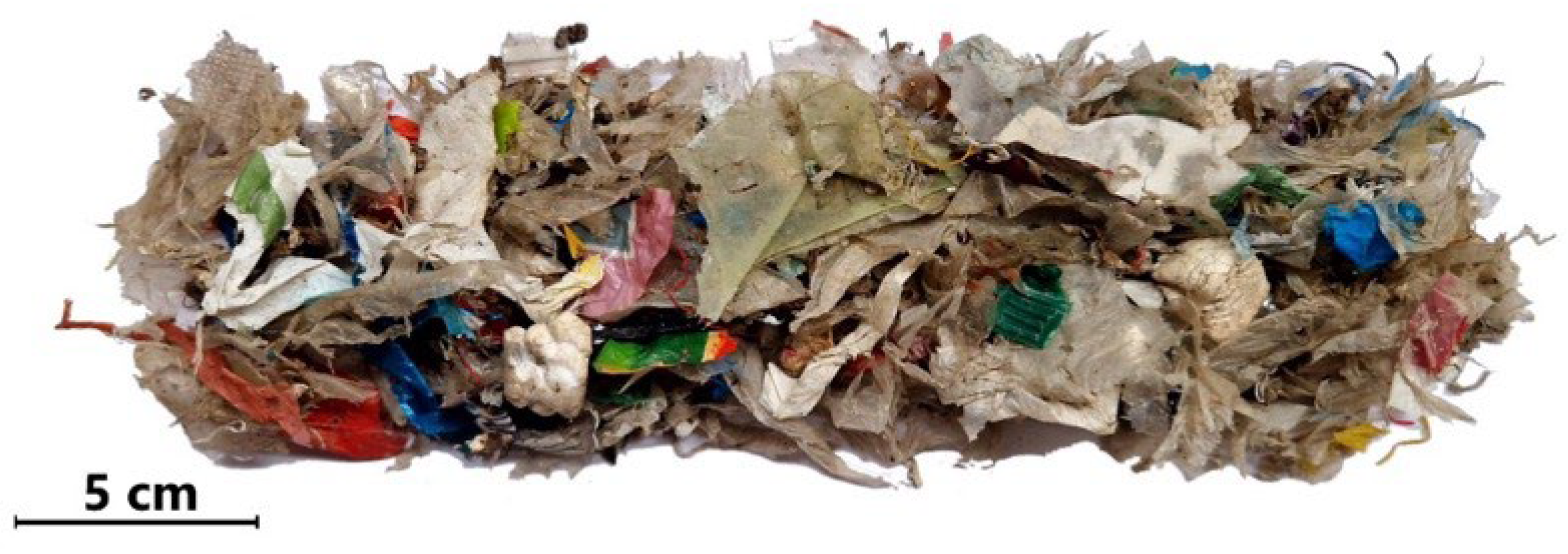
The experimental section describes the input SRF material and the process of the modification of properties through a binder-free pelletisation process. The experiments were carried out in the experimental laboratories of the ENET Centre, Centre for Energy and Environmental Technologies, and in the laboratory of Bulk Materials Centre, Department of Mining Engineering and Safety, Faculty of Mining and Geology, VSB—Technical University of Ostrava, Ostrava, Czech Republic.

2.1. Input Material

The fuel used for the purpose of this study was based on a SRF delivered by the OZO Ostrava s.r.o. waste-managing company situated in Ostrava, Czech Republic. This waste collection and utilisation company operates across the region of Moravia-Silesia, where industrial and municipal waste fractions including separated biowaste are collected and delivered to the sorting and processing line. The description and environmental impact of this modern and advanced line are described in the study of Výtisk et al. [28]. The final product is sold mainly to cement producers, while the capacity of incineration power plants is negligible nowadays.
Following the specific demand, wood-free SRF was delivered in a fluff form for further processing, analyses, and utilisation in a combustion unit. Granulometry of the input feedstock was in the range of 1 to 25 mm. The material composition was estimated to consist of approximately 60 wt.% of plastics, 20 wt.% of paper including cardboard, 15 wt.% of textiles, and 2 wt.% of inert fractions such as non-ferrous metals, glass, etc., according to the producer’s information (Figure 1).

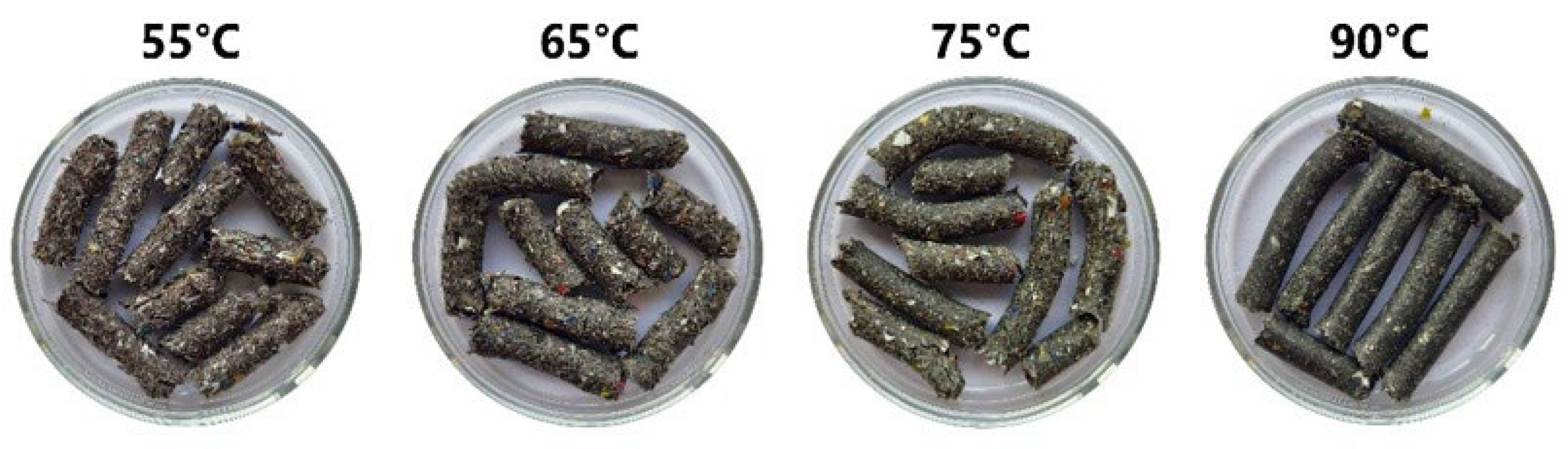
2.2. Pelletisation Process Description

The main objective of the mechanical treatment, specifically the pelletisation process, is to increase the energy density of materials and improve their thermochemical properties for subsequent processes [29]. As a suitable material for pelletisation, the following thermochemical conversion could be considered: biomass (including the alternative biomass), SRF and various other waste materials, or sewage sludge. This process has several advantages, but there are also a few concerns that are important to consider. The drawbacks of pelletising are mainly related to the intensive energy consumption of the process itself. High temperatures and pressures must be applied to achieve the desired pellet properties. If such energy is generated from fossil resources, the environmental aspects of the process are impacted [30]. The energy consumption of pelletising depends on many factors such as the type of input material, particle size, moisture content of the raw material, and the desired properties of the resulting pellets. In general, it is estimated that the pelletisation process requires approximately 16–49 kWh of energy per tonne of pellets produced [12]. Such an energy demand is significant, which is important to consider when planning the production process and optimising the energy efficiency.
In this study, pelletisation was carried out on a 14–175 flat-bed pelletising press (Amandus Kahl, Reinbek, Germany). This laboratory pellet press combines a robust design with advanced technology, a power of 3 kW, and a capacity of 10–50 kg·h−1, depending on the material used. The energy consumption of 0.06–0.3 kWh·kg−1 can be considered reasonable. However, industrial applications of larger scale possess with increased cost-effectiveness. This pelletising press has two cylindrical rolls with a diameter of 130 mm, width of 29 mm, matrix with an outer diameter of 175 mm, and hole diameter of 6 mm. Together, they enable the compression of raw feedstock into pellets under high pressure. The advantage of this equipment is the control system for setting the speed of the rolls and determining the temperature of the die. The die temperature was measured with a thermocouple, which was placed at the side of the die. The resulting pelletisation temperatures were in the range of 50–95 °C.

2.3. Determination of the Physical Properties

2.3.1. Particle Size Distribution and Particle Shape

The CAMSIZER 3D (Microtrac Retsch GmbH, Haan, Germany) is a particle analyser and a digital image analysis tool that is used to characterise the morphological features of dry, bulk materials ranging in size from 20 μm to 3000 μm. The CAMSIZER 3D was used not only for the particle size analysis, but also for the quantification of the particle shape. By employing two digital cameras, images of particles are captured during their free fall. Two cameras and a dynamic procedure prevent particles from being captured solely in one orientation. As the particle falls, it creates a particle track that is used by software to determine the width and the length of each particle projection. This method eliminates the need for subjective image editing to eliminate overlapping particles. The largest value of all length measurements within a particle track is the “3D length”, the largest value of all width measurements is the “3D width”, and the smallest value of all width measurements is the “3D thickness” of the particle. The measured parameters are shown in Figure 2. Moreover, the CAMSIZER 3D adheres to a standardised approach for quantifying the particle shape set forth by the International Organization for Standardisation (ISO 9276-6, 2006; ISO 13322-2, 2008) [31,32].
The CAMSIZER 3D offers both quantitative and qualitative insights. Its dynamic image analysis technology provides detailed visual data, enabling comprehensive qualitative assessments of particle shapes such as circularity, sphericity, and aspect ratio b/l. The shape factors show the differences and deviations between the spherical and non-spherical particles. The particle shape is crucial for particle transportation, storage, and interactions with fluid or chemical reactions [33].
The individual particle shape parameters are indicators of the shape of the particles. For example, the sphericity parameter SPHT shows the proximity to a perfect circle. The sphericity indicates the roundness of the particle and is determined by Equation (1) [33,34].
S P H T = 4 π A p 2
A—area of the particle;
p—particle perimeter.
The spherical particles have SPHT equal to 1, however, most particles in the industry have SPHT < 1 [33].
Similarly, the circularity C tries to describe the proximity to roundness and is determined from the particle area A and perimeter p. For the sphericity, the circularity also has a spherical particle C equal to 1, and for those non-spherical, the values are smaller C > 1 [34].
C = 4 π A p 2
A—area of the particle;
p—particle perimeter.
A very useful and often used particle shape parameter is the aspect ratio b/l. It shows the ratio of a particle, which, in the case of elongated particles, such as pellets, is a very good indicator. As shown in Equation (3), the aspect ratio b/l is the ratio of the minimum length (a particle width) b to the maximum Feret diameter (a particle length) l [35].
b l = X C ,   m i n X F e ,   m a x = W i d t h L e n g t h
Spherical or cubical particles incline toward the aspect ratio b/l equal to 1, while an elongated particle, such as a needle-like or rectangular particle morphology, inclines to lower the aspect ratio b/l below 1 [35].
Individual particle shape parameters were measured for 20 particles from each material as a representative sample, and the mean and standard deviation were then determined from the resulting values.

2.3.2. Ultimate and Proximate Analysis

Standardised ultimate and proximate analyses were performed by using the CHNS628 device (determination of Cr, Hr, Nr) with the CHNS628S module (Sr) (both Leco, St. Joseph, MI, USA). The content of water (Wr) was determined gravimetrically using a VF110 electric furnace (Memmert, Schwabach, Germany), and the content of ash (Ar) using a LEO 5/11 furnace (LAC, Topolová, Czech Republic). The mass concentration of Or was calculated following the EN ISO 16993 standard [36]. The definition of lower heating value (LHVr) was performed in accordance with the ISO 18125 standard [37] by determining the higher heating value and consequent recalculation. The chlorine (Clr), fluorine (Fr), and mercury (Hgr) mass concentration contents were determined by a ContrAA 700 atomic absorption spectrometer (Analytik Jena, Jena, Germany), which allows for the sequential analysis of traces of metals and other elements. Air and N2O were used as oxidising agents, while acetylene was used as the fuel gas.

2.3.3. Wettability Index Determination

Moisture resistance, referred to as the wettability index (WI), characterises the ability of pellets to absorb water or other liquids in the context of pelletisation. This index is one of the factors used to evaluate pellet quality and compare the influence of the material used and the pelletisation process. Pellets with high WI tend to absorb liquids, which leads to degradation and disintegration; therefore, it is essential to store such pellets in dry, well-ventilated areas. On the contrary, a low WI indicates that the pellets are resistant toward soaking liquids, reducing the stringent storage requirements. WI was performed according to Equation (4), defined by Mahadeo et al. [38] as:
WI = m 2 m 1 m 1 × 100
m1—weight of the pellet before the test;
m2—weight of the pellet after the test.
The performed test consisted of immersing a selected pellet in distilled water for 60 s. The average value was subsequently calculated from the results. The WI value (in [%]) was determined as the average value of ten tests of one sample.

2.3.4. Pellet Durability Index

The pellet durability index (PDI) is a crucial factor in industrial pelletisation processes, providing essential feedback on the quality of the resulting pellets. The PDI is measured through a mechanical test that typically involves rotating the pellets in a drum or using another mechanism that simulates the real conditions to which the pellets are exposed during storage, transportation, and handling. A higher PDI value indicates that the pellets have greater resistance to the simulated forces, and their resistance to withstand disintegration or crushing is better.
In this research, the PDI was measured on an NHP 100 (Holmen, Stockholm, Sweden) device [39], which is designed to measure the strength of pellets in accordance with ISO 17831-1 [40]. Its use principle is that a sample of pellets is placed in a chamber with perforated walls, and due to an air flow of 70 mbar, the pellets are buoyant and bump against each other and the walls of the chamber, causing crumbling. The sample is then sieved through a 3.15 mm sieve. The PDI value is defined by Equation (5).
PDI = m 2 m 1 × 100
m1—weight of the pellet before the test;
m2—weight of the pellet after the test.
The test was run for 30 s. According to EN ISO 17225-6 [41], the minimum resistance value of bio-pellets and non-wood pellets is set at 96%. The PDI value (in [%]) was determined as the average value of ten tests of one sample.

2.3.5. Hardness

The hardness of pellets is another factor determining the resistance of a pellet to mechanical effects. The hardness of the pellets was measured using a Hercules L (Amandus Kahl, Germany) device. The test determines the weight load in [kg] at which the tested pellet will break or crush. The hardness value was determined as the average of ten tests on one sample. This test simulated the compressive stress on the pellets during storage in silos and crushing during transportation and handling. The pellet hardness value was determined as the average value of ten tests of one sample.

2.3.6. Bulk Density

Bulk density is the physical property of a material that indicates the weight of the material per unit volume when the material is loosely packed (i.e., not externally compressed), and represents how tightly or loosely the particles of the material are arranged in a volume. In our case, this factor allowed us to compare the volume of the raw SRF material with its pelletised form and evaluate the impact of the process. The bulk density value was determined as the average value of ten tests of one sample.

2.3.7. Particle Density

Particle density in pelletisation is defined as the weight of a pellet per unit volume. It is influenced by the input material and the pelletisation process. Higher values may indicate pellet compactness and bulk compressibility. Particle density was determined by gravimetric measurement using the Archimedes principle (buoyancy method) on a JEW-DNY-43 (Mettler Toledo, Columbus, OH, USA) device with an accuracy of 0.001 g·cm−3. Particle density was determined as the average value of ten tests of one sample.

3. Results

3.1. Characterisation of Raw Input Material and Pelletisation Process

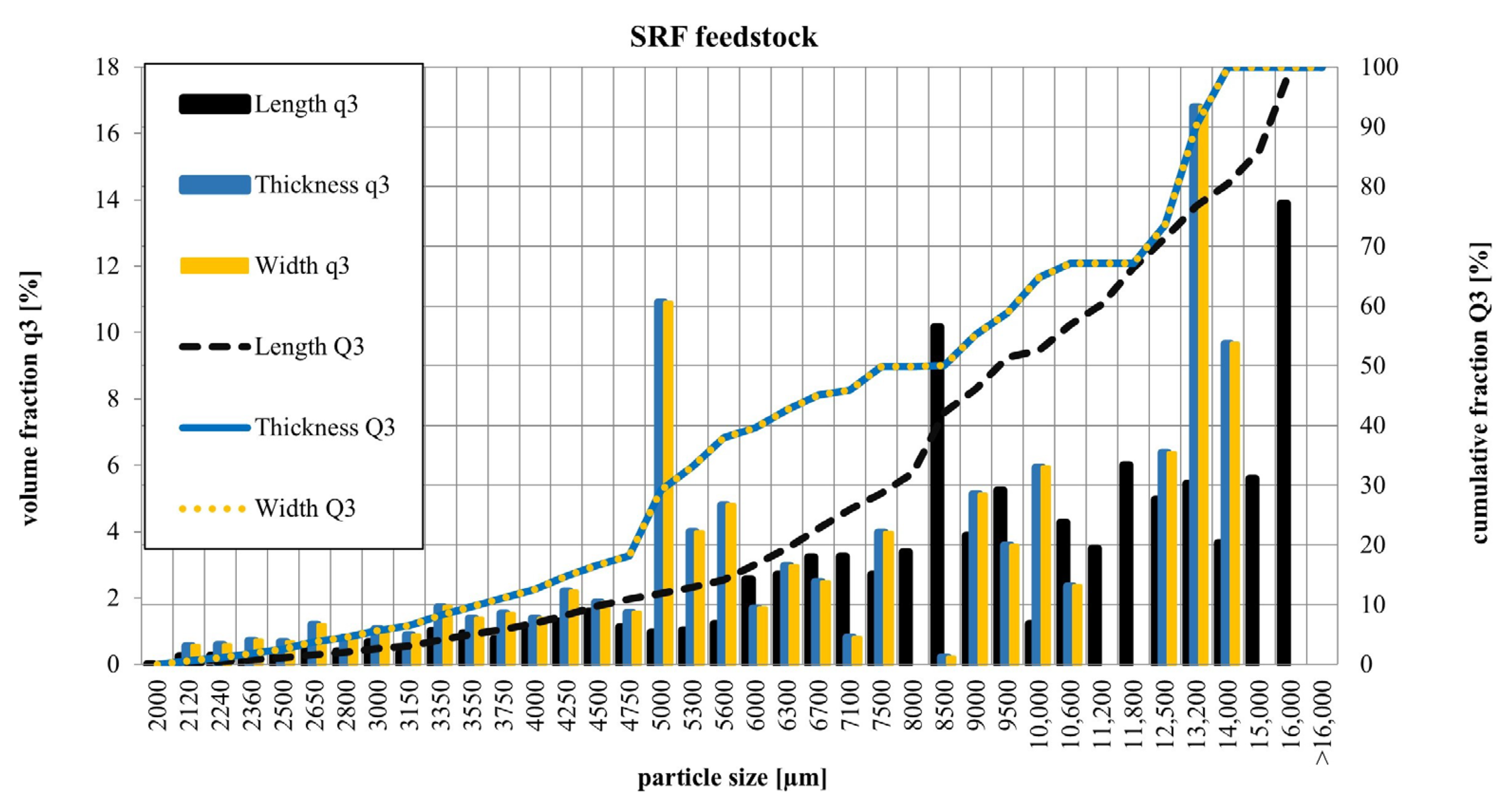
3.1.1. Particle Size Distribution of SRF

The particle size distribution characterisation values are shown in Table 1, showing d10, d50, and d90, respectively. The volume q3 and cumulative Q3 fractions were measured for the length, width, and thickness of the SRF material. The values of d10, d50, and d90 provide information regarding the particle sizes. The dimensions at which 10, 50, and 90% of a sample’s mass is comprised of smaller particles are indicated by d10, d50, and d90, respectively.

3.1.2. The Ultimate and Proximate Analysis

The results of the ultimate and proximate analysis of the pelletised SRF and certified SW pellets are presented in Table 2.
The results of the ultimate and proximate analysis of the SRF pellets and certified SW pellets showed a significant LHV difference of more than 13 MJ·kg−1 in favour of the SRF pellets. This also indicates a higher Cr and reduced Wr in the material. The disadvantage of the SRF material compared with SW pellets was the higher Ar content (nearly fiftyfold). The higher Ar is given mainly by the inert fraction in the input material. The increased value of volatile matter in the case of SRF pellets may mean a necessity of slightly different requirements for the combustion chamber dimensions [50]. A significant difference was observed in the Or content, where the SRF value was 10.42 wt.% compared with 39.7 wt.% for the SW pellets. Pelleted fuels with higher Or content offer several advantages, such as enhanced combustion efficiency, usually resulting in better energy release and reduced emissions. Additionally, the increased Or supports faster ignition, improving the overall combustion efficiency. However, there are also disadvantages including an increased risk of oxidation during storage and the potential for spontaneous combustion if not properly managed. Additionally, their stability over extended periods is diminished, making them unsuitable for long-term storage [51].
The Nr content for both materials was relatively low (not exceeding 0.6 wt.%), while in the case of the SRF pellets, the Nr was about three times higher than in the case of SW pellets, which could cause a more intense formation of fuel NOx during the combustion process, as was presented in previous studies with alternative fuels [29]. Moreover, the significantly higher LHV in the case of SRF pellets could cause a completely different combustion process course connected with local temperature peaks, resulting in the higher presence of thermal NOx in the flue gas [52].
Quite similar energy values to our study were achieved by Tokmurzin et al. [1], who utilised SRF material of the following composition: 80 wt.% mixed plastics from packaging, 10 wt.% wastepaper and woody biomass, and 10 wt.% HDPE. The LHV of this material was 24.7 MJ·kg−1, and the Cr and Ar contents were 68.86 wt.% and 9.21 wt.%, respectively. Notably lower LHV of 20.86 MJ·kg−1 for the SRF, composed mainly of wastepaper, plastic, and wood at undefined ratios, was presented in the study by Wu et al. [53]. This was mainly caused by a higher Wr (5.2 wt.%) and significantly lower Cr (58.0 wt.%). In the study of Čespiva et al. [54], an SRF feedstock of 40 wt.% wood, 30 wt.% plastics, 15 wt.% paper, 10 wt.% textile, and 5 wt.% defined as other, was used in a fixed-bed gasification reactor with outstanding results. Taking the diversity of the SRF compositions into consideration, which differ according to the input feedstock quality and composition, sorting technique, etc., it is very difficult to directly compare these fuels with each other.
The Clr content in the SRF was relatively high and originated from the PVC, being one of the main components. The reached value was in the range of previously presented studies aimed at SRF, such as the studies by Daouk et al. [55] (0.3 and 1.1 wt.%), Sarc et al. [56] (1.08 to 1.38 wt.%), and Edo-Alcón et al. [57] (0.64 to 1.71 wt.%). Moreover, it was completely in accordance with the previous study by Dziok et al. [58], representing the Cl analysis for different SRF batches. The Cl in coal usually ranges between 0.005 and 1 wt.%, while the increased values are mainly represented by British, American, and Indian coals [59]. The Cl content could be a source of potential problems when it comes to combustion, with special emphasis on two issues. One is connected to the potential formation of deposits on the heat exchanging surfaces of appliances (boilers), which is caused by the formation of salts such as NaCl or KCl [60]. The other is related to formation of polychlorinated dibenzodioxin and polychlorinated dibenzofuran (PCDD/F) [61]. However, a correlation between the Cl content and PCDD/F is not straightforward, and the formation of the carbon–Cl bond is a complex process, related to the conditions of the combustion process and fly ash characteristics.
Fr was detected in the SRF pellets. Hgr was also found in an amount of 0.1 mg·kg−1. This value is in line with the previously presented studies by Bury et al. [62] (up to 0.85 mg·kg−1), Hilber et al. [63] (0.1 to 0.16 mg·kg−1), and Stogiannis et al. [64] (0.322 to 0.548 mg·kg−1). The Hg content in coal ranges between 0.003 and 1 mg·kg−1, while the mean values of the analyses of wide pallet of fuels from different sources, were taken into account in the study by Zhao et al. [65].

3.1.3. Pelletisation Process

No further mechanical treatment or additives were required for the pelletisation process, which supports our objective of SRF pellet production without an added production cost. During the pelletisation of SRF material using a laboratory pellet press, 21 kg of pellets were produced per hour with an energy consumption of 1.9 kWh. After conversion, the consumed energy amounted to 90.48 kW per tonne of SRF pellets. The particle size distribution of the raw SRF material clearly exceeded the standard size range of SW used for pellet production, which has consequences for the pelletisation itself. At the beginning of the process, at a low matric temperature equal to 45 °C, the quality of the pellets did not meet the requested hardness, and obvious particle degradation occurred. As the temperature of the matrix was gradually increased, the pellets became harder, and the quality of the material plasticised. The die temperature was measured using a thermocouple sensor installed on the pellet press. To find the best pellet quality with various temperatures used for pelletisation, three temperatures were selected, at which samples were taken for testing. By increasing the temperature to 55, 65, and 75 °C, the material heated up, the plasticisation permeated the whole pellet, and the pellet structure changed, as shown in Figure 3.
When the temperature reached 90 °C, full plasticisation occurred, the material melted, and pelletisation was interrupted. The pellets at this temperature showed the best structure and quality, however, due to the interruption of the pelletisation process, the pellet quantity was not sufficient nor suitable for high volume production. The physical properties were measured for pellets at temperatures of 55, 65, and 75 °C.
The outputs of the pelletisation were four batches of SRF pellets with a diameter of 6 mm, produced in four different temperature settings. The resulting SRF pellets (75 °C) are shown in Figure 4 (left). The commercial EN plus A1 certified SW pellets are shown in Figure 4 (right).

3.2. Physical Properties of Pellets

The measured physical properties of the produced pellets were a crucial aspect for the selection of the pellet variant that was considered for the following studies on the combustion process evaluation.
Particle size distribution graphs show the undersieved fractions, where the particle size is shown on the x-axis and either the cumulative percentage or volume fraction on the y-axis. The cumulative curve Q3 indicates the percentage of undersieved particles smaller than a specific size, while the volume fraction curve q3 shows the proportion of total particle volume within the size range. The particle size distribution of the raw SRF is shown in Figure 5.

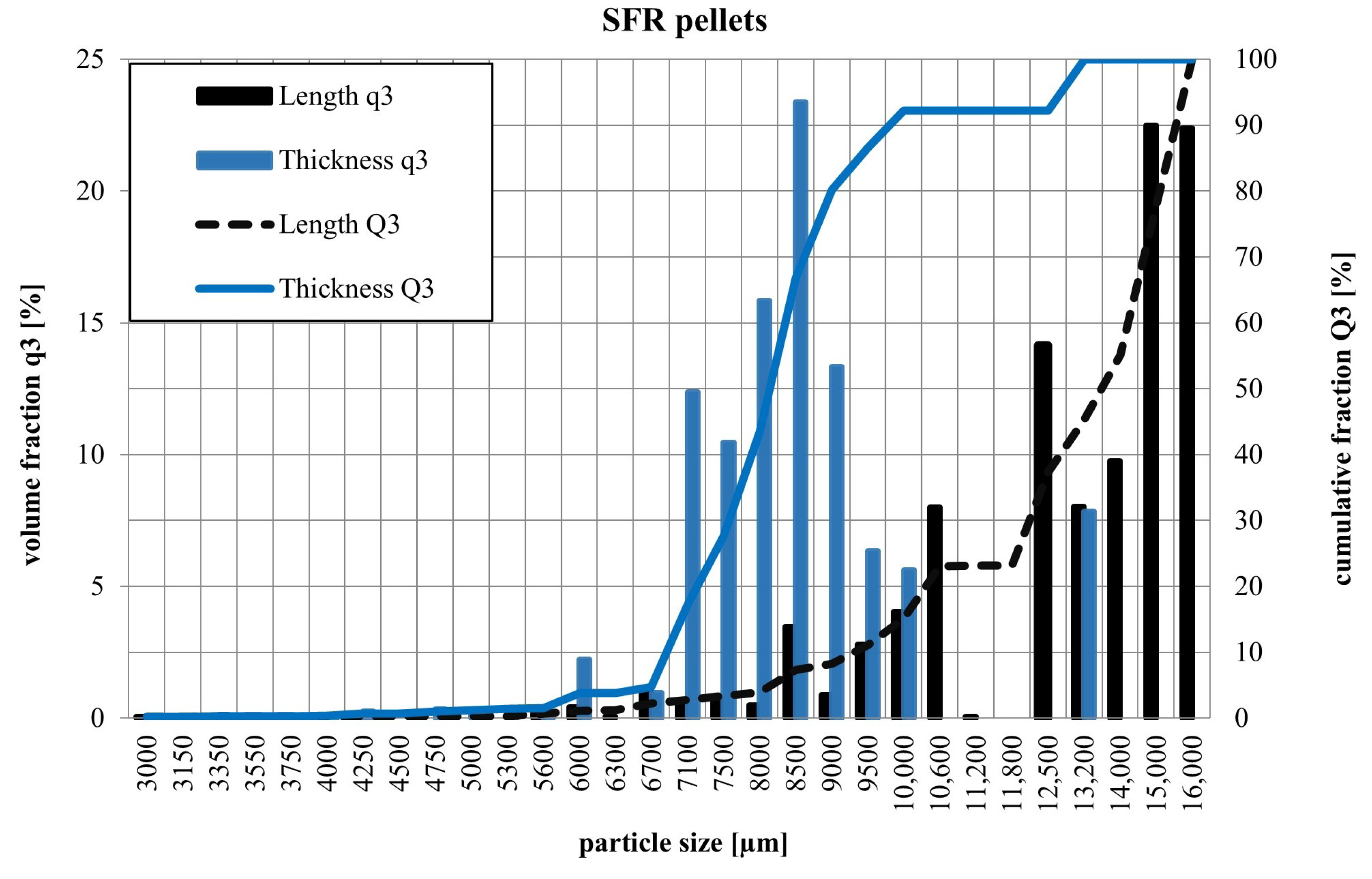
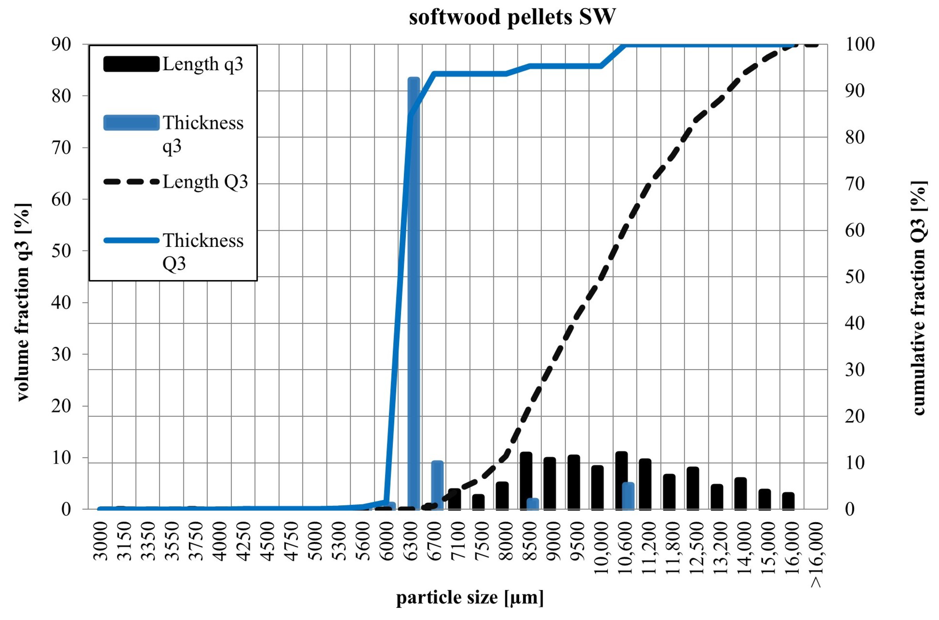
3.2.1. Particle Size Distribution of Pellets

The particle size distributions of the SRF and SW pellets are shown in Figure 6 and Figure 7. The volume q3 and cumulative Q3 fractions were measured for the length, width, and thickness of the pellets. Figure 6 and Figure 7 only present the q3 and cumulative Q3 curves for the length and thickness, as the width and thickness measurements were identical due to the shape of the pellets. This uniformity is a result of the characteristic elongated shape of the pellets, which is inherent to their production process.
Both the SRF and SW pellets exhibited identical width and thickness measurements, attributed to their characteristic elongated shape. This distinctive shape makes it challenging to fully describe the pellets using a single set of volume and cumulative distribution curves. The d10, d50, and d90 values for the respected measurements are provided in Table 3.
The SW pellets were slightly larger in diameter, which was due to the commercial production technology, which is probably different from the machine used for SRF production. The purchase of the SW pellets was associated with their original packaging and transport. This handling degraded the pellets, which can be seen in the particle size distribution curves. Although the SW pellets had a similar appearance to the experimentally-produced SRF pellets, their length was shorter due to breakage during handling.
The SRF pellets were longer than the commercial SW pellets and had a regular cylindrical shape. The cylindrical shape was caused by the production technology, where the pellet is forced through a hole of the following diameter of the pellet. This produces a uniform width and thickness of the pellets, which is given by the diameter size.

3.2.2. Particle Shape

The particle shape parameters of sphericity SPHT, circularity C, and aspect ratio b/l were measured on a CAMSIZER 3D. Twenty particles of each material, SRF pellets and SW pellets, were selected as a representative sample, and their mean values and relative deviations are given in Table 4. To calculate the shape parameters, Equations (1)–(3) were used, and the standard deviation was calculated in Excel software.
The SW pellets were gathered as EN plus A1 certified SW in a bulk. Their particle shape parameters showed less spherical particles in comparison to the SRF pellets (Table 4). This is due to the fact that their delivery was subjected to packaging and transport. The SRF pellets were produced in the laboratory and were thus not subjected to such significant degradation during transport.

3.2.3. Wettability Index

The results of the wettability index are shown in Figure 8. The test was performed for the pellets produced at 55 °C, 65 °C, and 75 °C and for the certified SW pellets.
The data revealed significant differences between the certified SW and SRF pellets. The presence of plastic material in the SRF pellets provided undeniable advantages, with the lowest temperature resulting in nearly half the SW value. The most notable effect of pelletising temperature on WI occurred between 55 °C and 65 °C, where even a 10 °C increase notably improved the quality of the SRF pellets. Pellets produced at 75 °C achieved the best WI results, reaching 0.5%. For the wood pellets, water adsorption is a critical limiting factor from a storage perspective. While the WI of wood pellets can be significantly reduced through aftertreatments like torrefaction—as demonstrated in the study by Grycová et al. [66] where the WI reached 0.59%—it is important to consider the substantial weight loss and reduced energy density associated with torrefaction as well as its impact on combustion behaviour [63]. Additionally, the study by Sykorova et al. [67] highlighted the positive influence of binders, such as lignosulfonate and flour, on improving the WI of hay pellets.

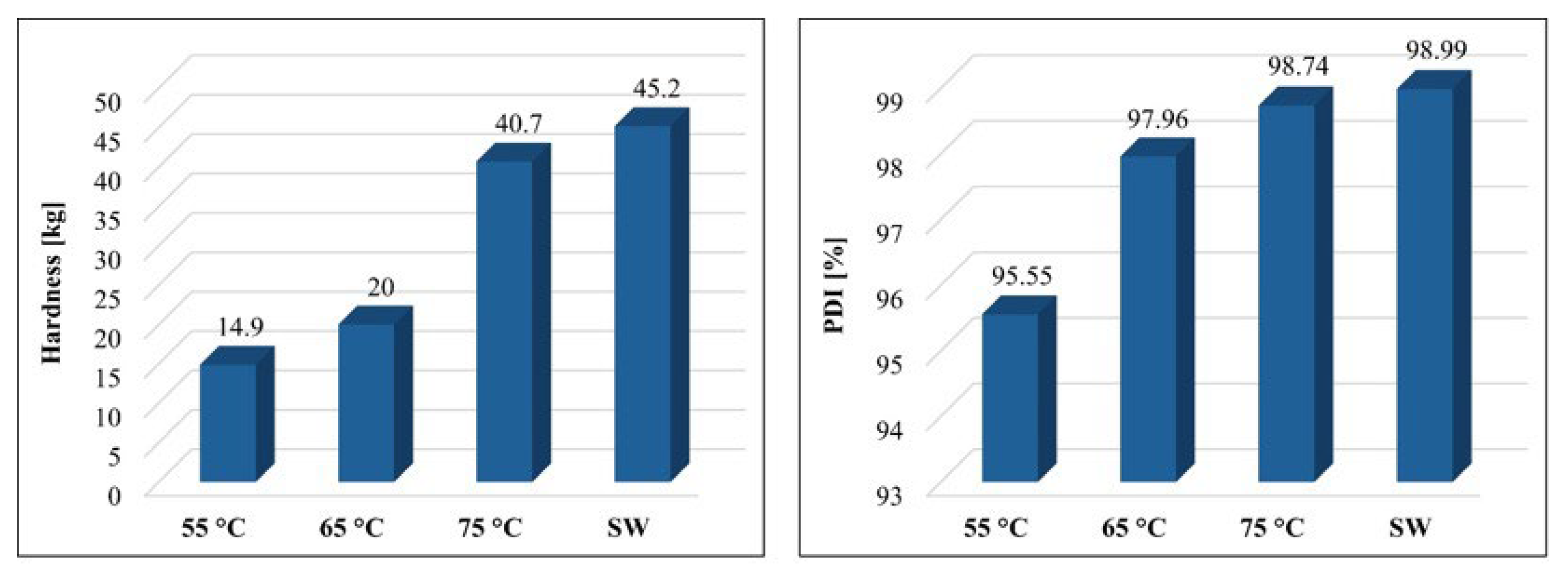
3.2.4. Hardness and Pellet Durability Index

The resistance of pellets to mechanical wear is one of the basic indicators of pellet quality. The graphs in Figure 9 show the results of pellet hardness and the PDI measurements.
Similarly to the WI data, there were again differences between the SRF pellet production temperatures. As the pelletisation temperature increased, the pellet hardness also increased. This course also continued above 75 °C in the case of Khaya senegalensis biomass, however, for the used SRF, it was impossible to hold the higher pelletising temperature as aforementioned [65]. While the WI showed the greatest change between the values obtained from pellets produced at temperatures of 55 °C and 65 °C for the hardness test, there was the most notable change between the temperatures of 65 °C and 75 °C when the pellet hardened significantly. The value reached at 75 °C was very similar to the SW commercial pellets.
As can be seen from the graphs in Figure 9, the hardness of the pellets did not correspond to the PDI, which shows the effect of mechanical wear on the formation of particles below 3 mm in size. According to EN ISO 17225-6 [39], the minimum value of pellet resistance was set at 96% PDI. This value was reached by the SW pellets and SRF pellets produced at 65 °C and 75 °C, and mathematically, would be met approximately above 57 °C (considering even less favourable linear dependency).

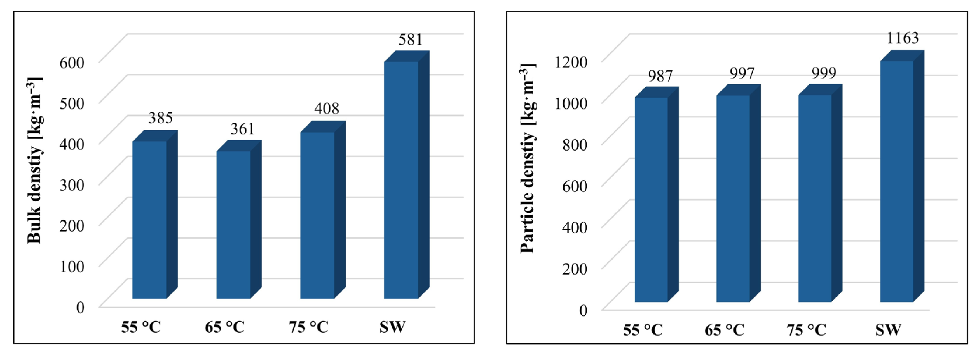
3.2.5. Bulk Density and Particle Density

The effect of pelletisation on the volume reduction in the input raw SRF material and the effect of pelletisation temperature on the bulk density and particle density are shown in Figure 10.
In a comparison of the bulk density SRF material and formed SRF pellets, there was a clear difference (Figure 10). By pelletising the SRF material, a tenfold reduction in bulk density could be achieved, from an input material value of 40 kg·m−3 to a value higher than 360 kg·m−3. Compared with the above results for the hardness and water absorption resistance, the effect of changing the pelletisation temperature on bulk density was not as reasonable. In this case, it was mainly the length and shape of the pellets and the arrangement of the particles during storage that were affected. The influence of particle density became noticeable when we compared the SRF pellets with the certified SW pellets. In these comparisons, a higher particle density led to an increase in bulk density. The difference in the particle density values of the SRF pellets and SW pellets was due to the specific weight of the input materials. Similar particle densities were reported for the pellets made using the raw and torrefied sawdust. Wang et al. [68] reported pellet densities ranging between 1050 and 1098 kg·m−3 for the raw sawdust pellets and between 951 and 992 kg·m−3 for pellets made of torrefied wood, depending on the process conditions of torrefaction. Luo et al. [69] obtained lower densities for torrefied sawdust, ranging between 700 and 900 kg·m−3, but for higher temperatures of torrefaction.

4. Conclusions

In this study, a comparative analysis was conducted based on the chemical and physical properties of EN plus A1 certified pellets against the experimentally-produced pellets from solid recovered fuel. The feasibility and effectiveness of producing high-quality SRF pellets from non-hazardous waste feedstock was explored. The chemical properties revealed notable differences, especially in the LHV parameter with a 13 MJ·kg−1 difference, favouring SRF pellets over the SW ones as well as a higher Cr mass concentration (42.0% increase) and lower Or (73.8% drop) and Wr (77.7% drop) fractions. On the contrary, the SRF pellets suffered a higher Ar mass concentration equal to 10.27 wt.%.
The subsequently investigated pelletisation process was performed under different operational forming temperature conditions. The forming temperature had a significant impact on the pellet hardness and PDI, which was found to exceed 96% for the SRF pellets produced at both 65 °C and 75 °C. It was found that a higher temperature sufficed, and even increased the mechanical resilience, while ensuring a very low mass fraction of water. However, the application at 90 °C led to intensive plasticisation and structural disruption. Thus, the optimal process temperature determined was 75 °C, as a suitable balance between outstanding material properties and a reliable process. Generally, it was found that a higher temperature made slightly denser pellets. This finding further supports production in elevated temperature regimes.
Compared with the EN plus A1 certified SW pellets, the SRF pellets showed a significant improvement in the energy content and mechanical properties, although they had a higher Ar content. Overall, the pellet hardness, PDI, and density (bulk and particle) were the mechanical-physical parameters that indicated better properties compared with the unprocessed SRF. The pelletised SRF possessed better transportability, energy density, easier handling, and better feeding into the combustion unit. This was based on the PDI, indicating pellet robustness for handling and transportation. Additionally, the pelletisation process resulted in a tenfold reduction in bulk density, significantly improving the transportability and storage aspects of the fuel material. The water resistance of the SRF pellets was also enhanced with elevated temperatures, reducing the risk of degradation during storage and handling. Under the appropriate conditions, the utilisation of SRF pellets could be beneficial. No further mechanical treatments or additives were required for the production of the SRF pellets, which supports the environmental and economic objectives.
The study confirms that the SRF pellets, with their improved mechanical and energy properties, meet the strict market requirements and can be fully utilised in existing combustion units without any modifications.
Future work should focus on optimising the production process further, exploring regulatory support, ensuring the reliable sourcing of high-quality waste materials, and addressing the high demand for alternative fuels. Moreover, the experimental approach of novel pellets testing in real combustion units will greatly broaden their usability. Furthermore, both environmental and economic sustainability should be comprehensively assessed by means of life cycle assessment and techno-economic analysis, respectively.

Author Contributions

Conceptualisation: R.P., J.D., L.J., J.R. and J.Č.; Data curation: R.P., J.D., L.J., and D.Ž. Formal analysis: R.P., J.D., J.R., J.Č., Ł.N., W.-M.Y. and D.P.V.; Funding acquisition: L.J., J.Č., and J.R. Investigation: J.D., R.P., and L.J.; Methodology: J.D., R.P., L.J. and D.Ž.; Project administration: L.J. and J.R.; Resources: L.J.; Supervision: L.J. and J.Č.; Validation: L.J. and J.Č.; Writing—original draft: R.P., J.D., J.Č. and J.R.; Writing—review and editing: D.P.V., Ł.N., K.M., A.M.-M. and W.-M.Y. All authors have read and agreed to the published version of the manuscript.

Funding

This publication is supported by the ESF in “Waste as an alternative source of energy” project, reg. nr. CZ.02.01.01/00/23_021/0008590 within the Programme Jahannes Amos Comenius, and by Technology Agency of the Czech Republic through the project “Recyclable Waste-derived Sorbents for Sustainable Process GHG Emissions Control”, TQ16000072. The European Just Transition Fund supported this work within the Operational Programme Just Transition under the aegis of the Ministry of the Environment of the Czech Republic, project CirkArena, number CZ.10.03.01/00/22_003/0000045. This paper was created as part of the project No. CZ.02.01.01/00/22_008/0004631 Materials and technologies for sustainable development within the Jan Amos Komensky Operational Program financed by the European Union and from the state budget of the Czech Republic.

Informed Consent Statement

Not applicable.

Data Availability Statement

The data presented in this study “Thermomechanical Treatment of SRF for Enhanced Fuel Properties [Data set]. In Fire (Version 1, s. 3434035)” are available on Zenodo. https://doi.org/10.5281/zenodo.14752769.

Conflicts of Interest

The authors declare no conflicts of interest.

List of Abbreviations

HDPEHigh density polyethylene
LHVLower heating value
MSWMunicipal solid waste
PCDD/FPolychlorinated dibenzodioxins/polychlorinated dibenzofurans
PDIPellet durability index
PEPolyethylene
PPPolypropylene
PVCPolyvinyl chloride
q3Volume fraction
Q3Cumulative fraction
SPHTSphericity
SRFSolid recovered fuel
SWSoftwood
WHOWorld Health Organisation
WIWettability index

References

  1. Tokmurzin, D.; Nam, J.Y.; Lee, T.R.; Park, S.J.; Nam, H.; Yoon, S.J.; Mun, T.-Y.; Yoon, S.M.; Moon, J.H.; Lee, J.G.; et al. High Temperature Flash Pyrolysis Characteristics of Waste Plastics (SRF) in a Bubbling Fluidized Bed: Effect of Temperature and Pelletizing. Fuel 2022, 326, 125022. [Google Scholar] [CrossRef]
  2. Kumar, A.; Samadder, S.R. A Review on Technological Options of Waste to Energy for Effective Management of Municipal Solid Waste. Waste Manag. 2017, 69, 407–422. [Google Scholar] [CrossRef]
  3. Nasrullah, M.; Vainikka, P.; Hannula, J.; Hurme, M. Elemental Balance of SRF Production Process: Solid Recovered Fuel Produced from Commercial and Industrial Waste. Fuel 2015, 145, 1–11. [Google Scholar] [CrossRef]
  4. Valin, S.; Ravel, S.; Pons de Vincent, P.; Thiery, S.; Miller, H. Fluidized Bed Air Gasification of Solid Recovered Fuel and Woody Biomass: Influence of Experimental Conditions on Product Gas and Pollutant Release. Fuel 2019, 242, 664–672. [Google Scholar] [CrossRef]
  5. Jerzak, W.; Mlonka-Mędrala, A.; Gao, N.; Magdziarz, A. Potential of Products from High-Temperature Pyrolysis of Biomass and Refuse-Derived Fuel Pellets. Biomass Bioenergy 2024, 183, 107159. [Google Scholar] [CrossRef]
  6. Recari, J.; Berrueco, C.; Puy, N.; Alier, S.; Bartrolí, J.; Farriol, X. Torrefaction of a Solid Recovered Fuel (SRF) to Improve the Fuel Properties for Gasification Processes. Appl. Energy 2017, 203, 177–188. [Google Scholar] [CrossRef]
  7. Aragon-Briceño, C.; Pożarlik, A.; Bramer, E.; Brem, G.; Wang, S.; Wen, Y.; Yang, W.; Pawlak-Kruczek, H.; Niedźwiecki, Ł.; Urbanowska, A.; et al. Integration of Hydrothermal Carbonization Treatment for Water and Energy Recovery from Organic Fraction of Municipal Solid Waste Digestate. Renew. Energy 2022, 184, 577–591. [Google Scholar] [CrossRef]
  8. Čespiva, J.; Jadlovec, M.; Výtisk, J.; Serenčíšová, J.; Ochodek, T.; Honus, S. Softwood and Srf Gasification Residual Chars as Sorbents for Flue Gas Mercury Capture. SSRN Electron. J. 2022, 29, 1–16. [Google Scholar] [CrossRef]
  9. Čespiva, J.; Wnukowski, M.; Skřínský, J.; Perestrelo, R.; Jadlovec, M.; Výtisk, J.; Trojek, M.; Câmara, J.S. Production Efficiency and Safety Assessment of the Solid Waste-Derived Liquid Hydrocarbons. Environ. Res. 2024, 244, 117915. [Google Scholar] [CrossRef]
  10. Sikkema, R.; Steiner, M.; Junginger, M.; Hiegl, W.; Hansen, M.T.; Faaij, A. The European Wood Pellet Markets: Current Status and Prospects for 2020. Biofuels Bioprod. Biorefining 2011, 5, 250–278. [Google Scholar] [CrossRef]
  11. Ibitoye, S.E.; Jen, T.-C.; Mahamood, R.M.; Akinlabi, E.T. Densification of Agro-Residues for Sustainable Energy Generation: An Overview. Bioresour. Bioprocess. 2021, 8, 75. [Google Scholar] [CrossRef] [PubMed]
  12. Stelte, W.; Sanadi, A.R.; Shang, L.; Holm, J.K.; Ahrenfeldt, J.; Henriksen, U.B. Recent Developments in Biomass Pelletization—A Review. Bioresources 2012, 7, 4451–4490. [Google Scholar] [CrossRef]
  13. Del Zotto, L.; Tallini, A.; Di Simone, G.; Molinari, G.; Cedola, L. Energy Enhancement of Solid Recovered Fuel within Systems of Conventional Thermal Power Generation. Energy Procedia 2015, 81, 319–338. [Google Scholar] [CrossRef]
  14. Lei, R.; Xu, Z.; Xing, Y.; Liu, W.; Wu, X.; Jia, T.; Sun, S.; He, Y. Global Status of Dioxin Emission and China’s Role in Reducing the Emission. J. Hazard. Mater. 2021, 418, 126265. [Google Scholar] [CrossRef]
  15. Song, S.; Chen, K.; Huang, T.; Ma, J.; Wang, J.; Mao, X.; Gao, H.; Zhao, Y.; Zhou, Z. New Emission Inventory Reveals Termination of Global Dioxin Declining Trend. J. Hazard. Mater. 2023, 443, 130357. [Google Scholar] [CrossRef]
  16. Garcia-Maraver, A.; Rodriguez, M.L.; Serrano-Bernardo, F.; Diaz, L.F.; Zamorano, M. Factors Affecting the Quality of Pellets Made from Residual Biomass of Olive Trees. Fuel Process. Technol. 2015, 129, 1–7. [Google Scholar] [CrossRef]
  17. Lorber, K.E.; Sarc, R.; Aldrian, A. Design and Quality Assurance for Solid Recovered Fuel. Waste Manag. Res. J. A Sustain. Circ. Econ. 2012, 30, 370–380. [Google Scholar] [CrossRef]
  18. Ridout, A.J.; Carrier, M.; Görgens, J. Fast Pyrolysis of Low and High Ash Paper Waste Sludge: Influence of Reactor Temperature and Pellet Size. J. Anal. Appl. Pyrolysis 2015, 111, 64–75. [Google Scholar] [CrossRef]
  19. Kruszelnicka, W.; Hlosta, J.; Diviš, J.; Gierz, Ł. Study of the Relationships between Multi-Hole, Multi-Disc Mill Performance Parameters and Comminution Indicators. Sustainability 2021, 13, 8260. [Google Scholar] [CrossRef]
  20. Velis, C.A.; Longhurst, P.J.; Drew, G.H.; Smith, R.; Pollard, S.J.T. Production and Quality Assurance of Solid Recovered Fuels Using Mechanical—Biological Treatment (MBT) of Waste: A Comprehensive Assessment. Crit. Rev. Environ. Sci. Technol. 2010, 40, 979–1105. [Google Scholar] [CrossRef]
  21. De la Torre-Bayo, J.J.; Zamorano, M.; Torres-Rojo, J.C.; Rodríguez, M.L.; Martín-Pascual, J. Analyzing the Production, Quality, and Potential Uses of Solid Recovered Fuel from Screening Waste of Municipal Wastewater Treatment Plants. Process Saf. Environ. Prot. 2023, 172, 950–970. [Google Scholar] [CrossRef]
  22. Žurovec, D.; Jezerská, L.; Nečas, J.; Hlosta, J.; Diviš, J.; Zegzulka, J. Spiral Vibration Cooler for Continual Cooling of Biomass Pellets. Processes 2021, 9, 1060. [Google Scholar] [CrossRef]
  23. García, R.; González-Vázquez, M.P.; Rubiera, F.; Pevida, C.; Gil, M.V. Co-Pelletization of Pine Sawdust and Refused Derived Fuel (RDF) to High-Quality Waste-Derived Pellets. J. Clean. Prod. 2021, 328, 129635. [Google Scholar] [CrossRef]
  24. DD CEN/TS 15359:2006; Solid Recovered Fuels—Specifications and Classes. European Commission, European Committee for Standardisation: Brussels, Belgium, 2006.
  25. PD CEN/TR 15508:2006; Key Properties on Solid Recovered Fuels to Be Used for Establishing a Classification System. European Commission, European Committee for Standardisation: Brussels, Belgium, 2006.
  26. Prismantoko, A.; Karuana, F.; Ghazidin, H.; Ruhiyat, A.S.; Adelia, N.; Prayoga Moch, Z.E.; Romelan, R.; Utomo, S.M.; Cahyo, N.; Hartono, J.; et al. Ash Deposition Behavior during Co-Combustion of Solid Recovered Fuel with Different Coals. Therm. Sci. Eng. Prog. 2024, 48, 102404. [Google Scholar] [CrossRef]
  27. Ramos Casado, R.; Arenales Rivera, J.; Borjabad García, E.; Escalada Cuadrado, R.; Fernández Llorente, M.; Bados Sevillano, R.; Pascual Delgado, A. Classification and Characterisation of SRF Produced from Different Flows of Processed MSW in the Navarra Region and Its Co-Combustion Performance with Olive Tree Pruning Residues. Waste Manag. 2016, 47, 206–216. [Google Scholar] [CrossRef]
  28. Výtisk, J.; Čespiva, J.; Jadlovec, M.; Kočí, V.; Honus, S.; Ochodek, T. Life Cycle Assessment Applied on Alternative Production of Carbon-Based Sorbents—A Comparative Study. Sustain. Mater. Technol. 2023, 35, e00563. [Google Scholar] [CrossRef]
  29. Ryšavý, J.; Horák, J.; Kuboňová, L.; Jaroch, M.; Hopan, F.; Krpec, K.; Kubesa, P. Beech Leaves Briquettes’ and Standard Briquettes’ Combustion: Comparison of Flue Gas Composition. Int. J. Energy Prod. Manag. 2021, 6, 32–44. [Google Scholar] [CrossRef]
  30. Zhou, C.; Zhang, Q.; Arnold, L.; Yang, W.; Blasiak, W. A Study of the Pyrolysis Behaviors of Pelletized Recovered Municipal Solid Waste Fuels. Appl. Energy 2013, 107, 173–182. [Google Scholar] [CrossRef]
  31. ISO 9276-6:2008; Representation of Results of Particle Size Analysis—Part 6: Descriptive and Quantitative Representation of Particle Shape and Morphology. International Organization for Standardization: Geneva, Switzerland, 2008. Available online: https://www.iso.org/standard/39389.html (accessed on 30 December 2024).
  32. ISO 13322-2:2021; Particle Size Analysis—Image Analysis Methods—Part 2: Dynamic Image Analysis Methods. International Organization for Standardization: Geneva, Switzerland, 2021. Available online: https://www.iso.org/standard/72566.html (accessed on 30 December 2024).
  33. Brown, D.J.; Vickers, G.T.; Collier, A.P.; Reynolds, G.K. Measurement of the Size, Shape and Orientation of Convex Bodies. Chem. Eng. Sci. 2005, 60, 289–292. [Google Scholar] [CrossRef]
  34. Patchigolla, K.; Wilkinson, D. Crystal Shape Characterisation of Dry Samples Using Microscopic and Dynamic Image Analysis. Part. Part. Syst. Charact. 2009, 26, 171–178. [Google Scholar] [CrossRef]
  35. Islam, S.F.; Hawkins, S.M.; Meyer, J.L.L.; Sharman, A.R.C. Evaluation of Different Particle Size Distribution and Morphology Characterization Techniques. Addit. Manuf. Lett. 2022, 3, 100077. [Google Scholar] [CrossRef]
  36. ISO 16993:2016; Solid Biofuels—Conversion of Analytical Results from one Basis to Another. International Organization for Standardization: Geneva, Switzerland, 2016. Available online: https://www.iso.org/standard/70098.html (accessed on 30 December 2024).
  37. ISO 18125:2017; Solid Biofuels—Determination of Calorific Value. International Organization for Standardization: Geneva, Switzerland, 2017. Available online: https://www.iso.org/standard/61517.html (accessed on 30 December 2024).
  38. Mahadeo, K. Study on Physical and Chemical Properties of Crop Residues Briquettes for Gasification. Am. J. Energy Eng. 2014, 2, 51. [Google Scholar] [CrossRef]
  39. Knarr, L.E.; Bowen, K.M.; Ferrel, J.; Moritz, J.S. Azomite, a Dacitic (Rhyolitic) Tuff Breccia, Included at 0.25% in Feed Manufactured with 32, 38, and 45 Mm Pellet Die Thicknesses Increased Pellet Production Rate by 5.0, 7.9, and 11.8%, Respectively. J. Appl. Poult. Res. 2024, 33, 100389. [Google Scholar] [CrossRef]
  40. ISO 17831-1:2015; Solid Biofuels—Determination of Mechanical Durability of Pellets and Briquettes. International Organization for Standardization: Geneva, Switzerland, 2015. Available online: https://www.iso.org/standard/60695.html (accessed on 30 December 2024).
  41. ISO 17225-6:2021; Solid Biofuels—Fuel Specifications and Classes Part 6: Graded Non-Woody Pellets. International Organization for Standardization: Geneva, Switzerland, 2021. Available online: https://www.iso.org/standard/76093.html (accessed on 30 December 2024).
  42. ISO 22167:2021; Solid Recovered Fuels—Determination of Content of Volatile Matter. International Organization for Standardization: Geneva, Switzerland, 2021. Available online: https://www.iso.org/standard/72716.html (accessed on 30 December 2024).
  43. ISO 18134-2:2024; Solid Biofuels—Determination of Moisture Content Part 2: Simplified Method. International Organization for Standardization: Geneva, Switzerland, 2024. Available online: https://www.iso.org/standard/86024.html (accessed on 30 December 2024).
  44. ISO 18122:2022; Solid Biofuels—Determination of Ash Content. International Organization for Standardization: Geneva, Switzerland, 2022. Available online: https://www.iso.org/standard/83190.html (accessed on 30 December 2024).
  45. ISO 16948:2015; Solid Biofuels—Determination of Total Content of Carbon, Hydrogen and Nitrogen. International Organization for Standardization: Geneva, Switzerland, 2015. Available online: https://www.iso.org/standard/58004.html (accessed on 30 December 2024).
  46. ISO 16994:2016; Solid Biofuels—Determination of Total Content of Sulfur and Chlorine. International Organization for Standardization: Geneva, Switzerland, 2016. Available online: https://www.iso.org/standard/70097.html (accessed on 30 December 2024).
  47. ISO 11724:2019; Solid Mineral Fuels—Determination of Total Fluorine in Coal, Coke and Fly Ash. International Organization for Standardization: Geneva, Switzerland, 2019. Available online: https://www.iso.org/standard/75881.html (accessed on 30 December 2024).
  48. ISO 18806:2019; Solid Mineral Fuels—Determination of Chlorine Content. International Organization for Standardization: Geneva, Switzerland, 2019. Available online: https://www.iso.org/standard/75466.html (accessed on 30 December 2024).
  49. ISO 15237:2016; Solid Mineral Fuels—Determination of Total Mercury Content of Coal. International Organization for Standardization: Geneva, Switzerland, 2016. Available online: https://www.iso.org/standard/70207.html (accessed on 30 December 2024).
  50. Koppejan, J.; van Ioo, S. The Handbook of Biomass Combustion and Co-Firing; Earthscan: Oxford, UK, 2008. [Google Scholar]
  51. Alakoski, E.; Jämsén, M.; Agar, D.; Tampio, E.; Wihersaari, M. From Wood Pellets to Wood Chips, Risks of Degradation and Emissions from the Storage of Woody Biomass—A Short Review. Renew. Sustain. Energy Rev. 2016, 54, 376–383. [Google Scholar] [CrossRef]
  52. Zhang, H.; Ye, X.; Cheng, T.; Chen, J.; Yang, X.; Wang, L.; Zhang, R. A Laboratory Study of Agricultural Crop Residue Combustion in China: Emission Factors and Emission Inventory. Atmos. Environ. 2008, 42, 8432–8441. [Google Scholar] [CrossRef]
  53. Wu, H.; Glarborg, P.; Frandsen, F.J.; Dam-Johansen, K.; Jensen, P.A.; Sander, B. Trace Elements in Co-Combustion of Solid Recovered Fuel and Coal. Fuel Process. Technol. 2013, 105, 212–221. [Google Scholar] [CrossRef]
  54. Čespiva, J.; Skřínský, J.; Vereš, J.; Wnukowski, M.; Serenčíšová, J.; Ochodek, T. Solid Recovered Fuel Gasification in Sliding Bed Reactor. Energy 2023, 278, 127830. [Google Scholar] [CrossRef]
  55. Daouk, E.; Sani, R.; Pham Minh, D.; Nzihou, A. Thermo-Conversion of Solid Recovered Fuels under Inert and Oxidative Atmospheres: Gas Composition and Chlorine Distribution. Fuel 2018, 225, 54–61. [Google Scholar] [CrossRef]
  56. Sarc, R.; Lorber, K.; Pomberger, R.; Rogetzer, M.; Sipple, E. Design, Quality, and Quality Assurance of Solid Recovered Fuels for the Substitution of Fossil Feedstock in the Cement Industry. Waste Manag. Res. J. A Sustain. Circ. Econ. 2014, 32, 565–585. [Google Scholar] [CrossRef]
  57. Edo-Alcón, N.; Gallardo, A.; Colomer-Mendoza, F.J. Characterization of SRF from MBT Plants: Influence of the Input Waste and of the Processing Technologies. Fuel Process. Technol. 2016, 153, 19–27. [Google Scholar] [CrossRef]
  58. Dziok, T.; Bury, M.; Burmistrz, P. Mercury Release from Municipal Solid Waste in the Thermal Treatment Process. Fuel 2022, 329, 125528. [Google Scholar] [CrossRef]
  59. Mazurek, I.; Skawińska, A.; Sajdak, M. Analysis of Chlorine Forms in Hard Coal and the Impact of Leaching Conditions on Chlorine Removal. J. Energy Inst. 2021, 94, 337–351. [Google Scholar] [CrossRef]
  60. Hardy, T.; Arora, A.; Pawlak-Kruczek, H.; Rafajłowicz, W.; Wietrzych, J.; Niedźwiecki, Ł.; Vishwajeet Mościcki, K. Non-Destructive Diagnostic Methods for Fire-Side Corrosion Risk Assessment of Industrial Scale Boilers, Burning Low Quality Solid Biofuels—A Mini Review. Energies 2021, 14, 7132. [Google Scholar] [CrossRef]
  61. Gullett, B.K.; Sarofim, A.F.; Smith, K.A.; Procaccini, C. The Role of Chlorine in Dioxin Formation. Process Saf. Environ. Prot. 2000, 78, 47–52. [Google Scholar] [CrossRef]
  62. Bury, M.; Dziok, T.; Borovec, K.; Burmistrz, P. Influence of RDF Composition on Mercury Release during Thermal Pretreatment. Energies 2023, 16, 772. [Google Scholar] [CrossRef]
  63. Hilber, T.; Thorwarth, H.; Stack-Lara, V.; Schneider, M.; Maier, J.; Scheffknecht, G. Fate of Mercury and Chlorine during SRF Co-Combustion. Fuel 2007, 86, 1935–1946. [Google Scholar] [CrossRef]
  64. Stogiannis, P.; Triantafillidis, A.; Amarantos, P.; Kontodimos, I.; Ketikidis, C.; Grammelis, P. Measuring the Concentration of Mercury for Automotive Shredded Residues Using the Direct Mercury Analyser. Eng. Proc. 2023, 56, 253. [Google Scholar] [CrossRef]
  65. Zhao, S.; Pudasainee, D.; Duan, Y.; Gupta, R.; Liu, M.; Lu, J. A Review on Mercury in Coal Combustion Process: Content and Occurrence Forms in Coal, Transformation, Sampling Methods, Emission and Control Technologies. Prog. Energy Combust. Sci. 2019, 73, 26–64. [Google Scholar] [CrossRef]
  66. Grycova, B.; Klemencova, K.; Jezerska, L.; Zidek, M.; Lestinsky, P. Effect of Torrefaction on Pellet Quality Parameters. Biomass Convers. Biorefinery 2023, 13, 13235–13243. [Google Scholar] [CrossRef]
  67. Sykorova, V.; Jezerska, L.; Sassmanova, V.; Honus, S.; Peikertova, P.; Kielar, J.; Zidek, M. Biomass Pellets with Organic Binders—Before and after Torrefaction. Renew. Energy 2024, 221, 119771. [Google Scholar] [CrossRef]
  68. Wang, C.; Peng, J.; Li, H.; Bi, X.T.; Legros, R.; Lim, C.J.; Sokhansanj, S. Oxidative Torrefaction of Biomass Residues and Densification of Torrefied Sawdust to Pellets. Bioresour. Technol. 2013, 127, 318–325. [Google Scholar] [CrossRef]
  69. Luo, H.; Niedzwiecki, L.; Arora, A.; Mościcki, K.; Pawlak-Kruczek, H.; Krochmalny, K.; Baranowski, M.; Tiwari, M.; Sharma, A.; Sharma, T.; et al. Influence of Torrefaction and Pelletizing of Sawdust on the Design Parameters of a Fixed Bed Gasifier. Energies 2020, 13, 3018. [Google Scholar] [CrossRef]
Figure 1. Input raw SRF material.
Fire 08 00057 g001
Figure 2. CAMSIZER 3D images capturing different particle dimensions during its free fall.
Fire 08 00057 g002
Figure 3. The produced SRF pellets for pelletising temperatures of 55 °C, 65 °C, 75 °C, and 90 °C.
Fire 08 00057 g003
Figure 4. Pellet materials—(left) SRF pellets, (right) SW pellets.
Fire 08 00057 g004
Figure 5. The particle size distribution (volume q3 and cumulative Q3) for the SRF feedstock’s length, thickness, and width.
Fire 08 00057 g005
Figure 6. The particle size distribution (volume q3 and cumulative Q3) for the SRF pellets’ length and thickness.
Fire 08 00057 g006
Figure 7. The particle size distribution (volume q3 and cumulative Q3) for the SW pellets’ length and thickness.
Fire 08 00057 g007
Figure 8. WI for the pellets formed at temperatures 55 °C, 65 °C, and 75 °C and for the certified SW pellets.
Fire 08 00057 g008
Figure 9. Hardness (left) and PDI (right) for the pellets formed at temperatures 55 °C, 65 °C, and 75 °C and for the certified SW pellets.
Fire 08 00057 g009
Figure 10. Bulk density (left) and particle density (right) for the pellets formed at temperatures of 55 °C, 65 °C, and 75 °C and for the certified SW pellets.
Fire 08 00057 g010
Table 1. Particle size distribution characterisation values of d10, d50, and d90 for the SRF pellets (ISO 13322-2) [32].
d10Standard
Deviation
d50Standard
Deviation
d90Standard Deviation
[µm][µm][µm][µm][µm][µm]
Length4541341938972415,7491716
Width3588265849466212,8081063
Thickness3588265849466212,8081063
Table 2. Ultimate and proximate analysis of the used fuels.
ParameterUnitSWSRFStandardUncertainty
Lower heating value (LHVr)[MJ·kg−1]17.4130.5EN 18125 [35]3.0%
Volatile matter (Vr)[wt.%]75.7583.13EN ISO 22167 [42]1.9%
Water (Wr)[wt.%]7.121.59EN ISO 18134-2 [43]3.1%
Ash (Ar)[wt.%]0.2410.27EN ISO 18122 [44]9.0%
Carbon (Cr)[wt.%]47.0966.9EN ISO 16948 [45]4.6%
Oxygen (Or)[wt.%]39.7010.42EN ISO 16993 [36]-
Hydrogen (Hr)[wt.%]5.638.61EN ISO 16948 [45]3.1%
Nitrogen (Nr)[wt.%]0.200.57EN ISO 16948 [45]6.1%
Total sulphur (Sr)[wt.%]<0.020.09EN ISO 16994 [46]6.4%
Chlorine (Clr)[wt.%]<0.011.18ISO 11724:2019 [47]37%
Fluorine (Fr)[wt.%]<0.02<0.02ISO 18806:2019 [48]-
Mercury (Hgr)[mg·kg−1]<0.10.1ISO 15237:2016 [49]0.01%
Table 3. Particle size distribution characterisation values of d10, d50, and d90 for the SRF and SW pellets (ISO 13322-2) [32].
d10Standard Deviationd50Standard Deviationd90Standard Deviation
[µm][µm][µm][µm][µm][µm]
SW
pellets
Length789249710,00471013,4331236
Thickness606973618269634984
Width606973618269634984
SRF
pellets
Length926472313,911114115,5381461
Thickness68268981621719641231
Width68268981621719641231
Table 4. The particle shape parameters of sphericity SPHT, circularity C, and aspect ratio b/l for the SRF and SW pellets.
Sphericity SPHT [–]Circularity C [–]Aspect Ratio b/l [–]
MeanStandard DeviationMeanStandard DeviationMeanStandard Deviation
SRF pellets0.370.060.610.050.670.06
SW pellets0.680.090.820.060.700.07
Disclaimer/Publisher’s Note: The statements, opinions and data contained in all publications are solely those of the individual author(s) and contributor(s) and not of MDPI and/or the editor(s). MDPI and/or the editor(s) disclaim responsibility for any injury to people or property resulting from any ideas, methods, instructions or products referred to in the content.

