
Improvement of the Performance of an Earth to Air Heat Exchanger for Greenhouse Cooling by the Incorporation of Water Finned Tubes—A Theoretical Approach

 , and
, and
Abstract
:1. Introduction
2. Materials and Methods
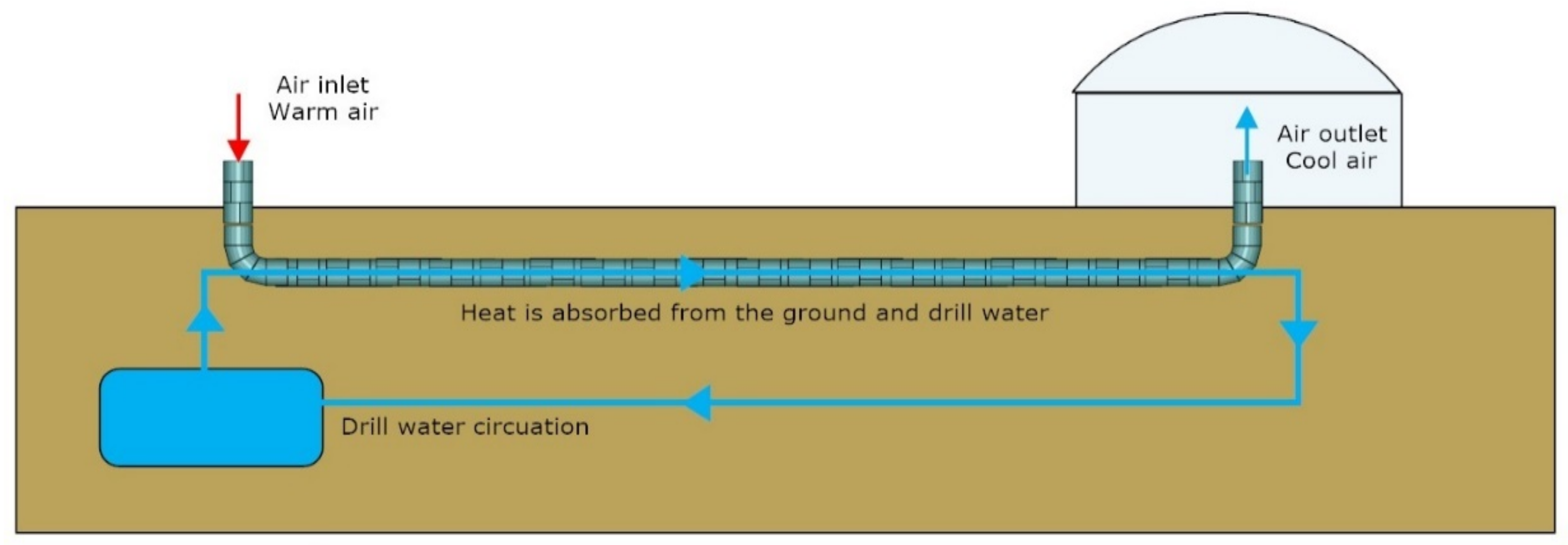
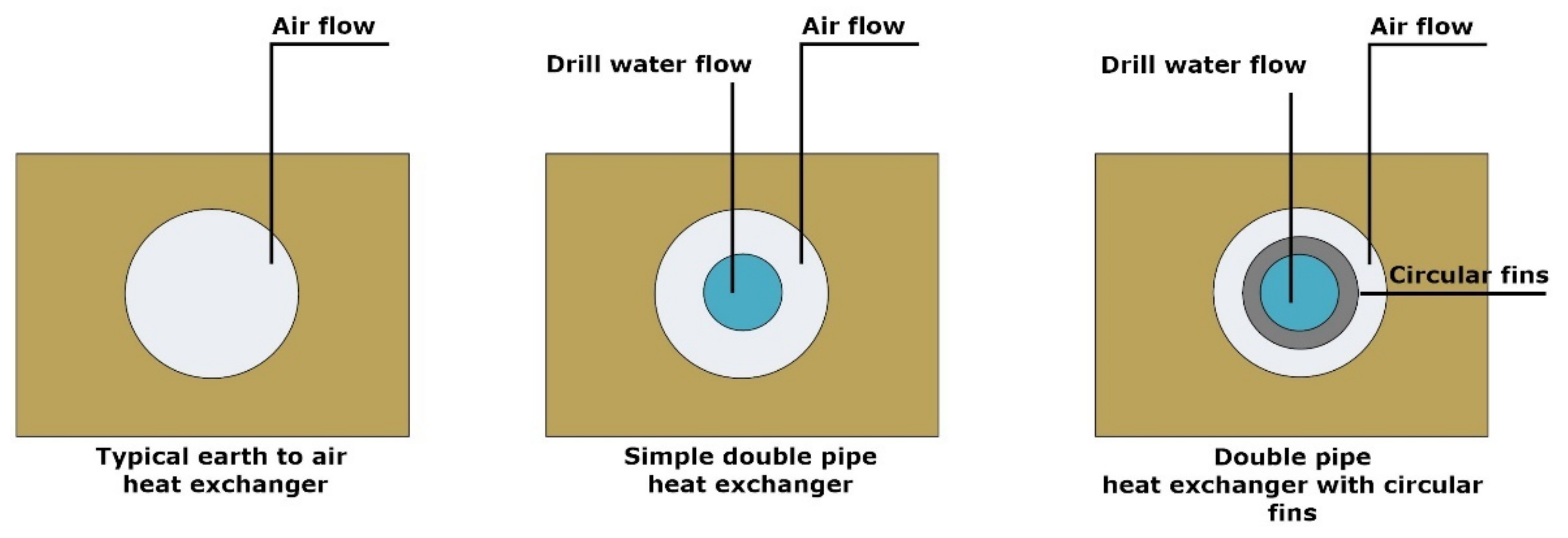
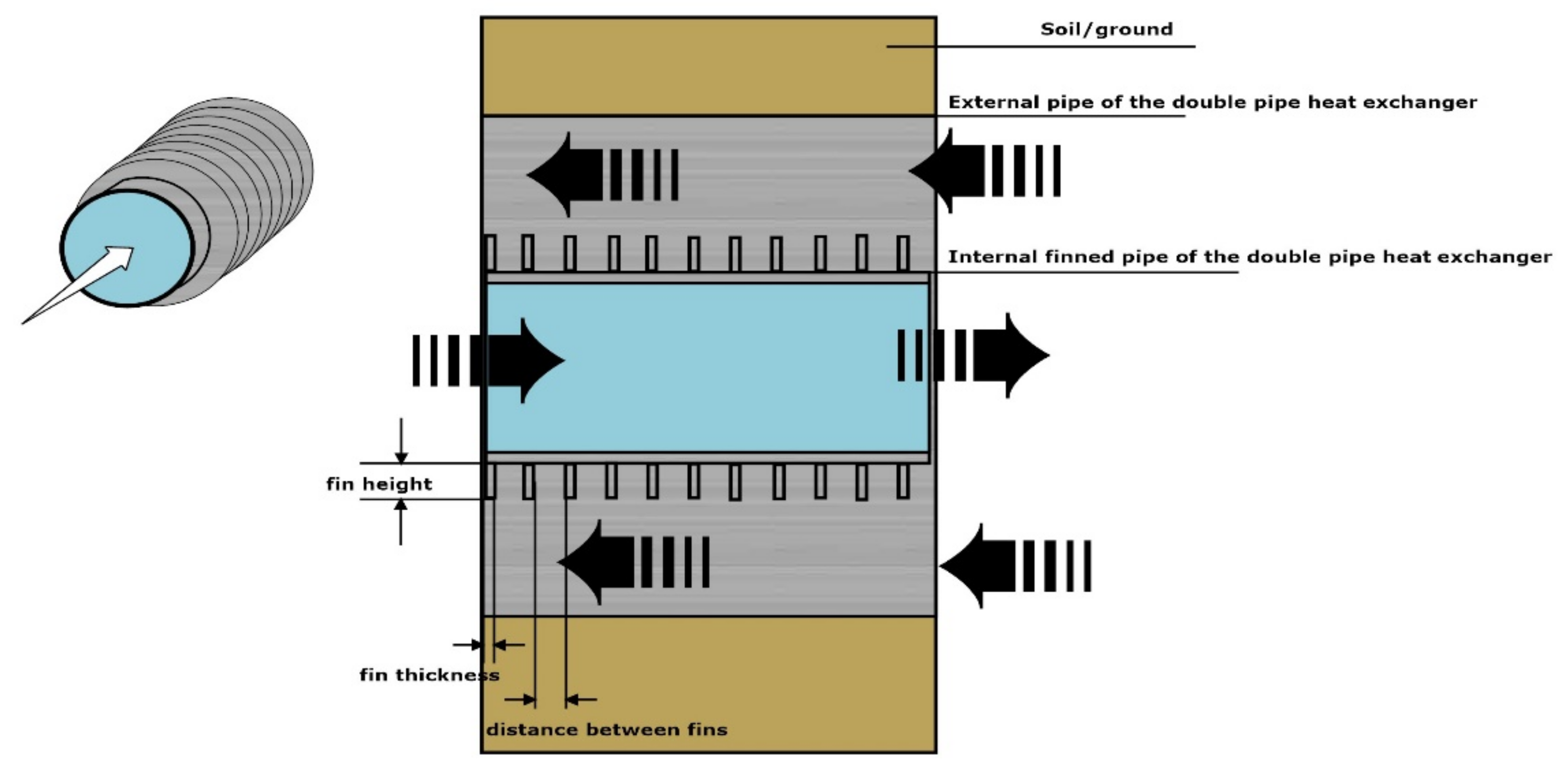
2.1. Theoretical Case Study Description
2.2. Mathematical Model
2.3. Assumptions and Initial Design Parameters Selection
3. Results
3.1. Energy Balance Calculations
3.2. Evaporative Heat Transfer Coefficient Caclulation
4. Discussion
5. Conclusions
Author Contributions
Funding
Data Availability Statement
Conflicts of Interest
Nomenclature
| A | heat transfer surface area (m2) |
| a | initial convection heat transfer coefficient for the pipe (W m−2 K−1) |
| ai | internal flow convection heat transfer coefficient (W m−2 K−1) |
| an | convection heat transfer coefficient (W m−2 K−1) |
| ao | external flow convection heat transfer coefficient (W m−2 K−1) |
| aR | adjusted convection heat transfer coefficient (W m−2 K−1) |
| modified convection heat transfer coefficient after the application of the fins (Wm−2 K−1) | |
| specific heat for the cold mean at average operation temperature (kJ kg−1 K−1) | |
| specific heat for the cold mean at average operation temperature (kJ kg−1 K−1) | |
| d | diameter (m) |
| db | depth of buried pipe (m) |
| dch | characteristic linear dimension (m) |
| dh | hydraulic diameter (m) |
| di | internal diameter of the annular cross section (m) |
| din | pipe internal diameter (m) |
| do | external diameter of the annular cross section (m) |
| f | friction factor |
| Gzd | Graetz number |
| h | overall heat transfer coefficient (W m−2 K−1) |
| kg | ground thermal conductivity (W m−1 K−1) |
| L | pipe length (m) |
| Lch | characteristic length of solid element in convective heat transfer |
| cold mean (water) flow rate (kg s−1) | |
| warm mean (air) flow rate (kg s−1) | |
| m | fin adjustment value |
| Nu | Nusselt number |
| Nud | Nusselt number for pipe with characteristic diameter d |
| Pr | Prandtl number |
| heat flow (W) | |
| Qg | heat loss to the ground (W) |
| rp | radius of pipe (m) |
| Re | Reynolds number |
| s | thickness of the internal pipe wall (m) |
| Τp | average pipe temperature (°C) |
| Tg | average ground temperature (°C) |
| u | velocity (m/s) |
| v | kinematic viscosity (m2/s−1) |
| ΔP | pressure drop (Pa) |
| temperature difference for the cold mean inlet and outlet (°C) | |
| temperature difference for the warm mean inlet and outlet (°C) | |
| ΔΤlog | logarithmic mean temperature difference (K) |
| δR | fin thickness (m) |
| δ1 | fin allocation (m) |
| η | dynamic viscosity (kg m−1 s−1) |
| λ | thermal conductivity (W m−1 K−1) |
| ξ | friction coefficient |
| ρ | air density (kg/m3) |
References
- Bucklin, R.A.; Henley, R.W.; McConnell, D.B. Fan and Pad Greenhouse Evaporative Cooling Systems—CIR1135; Department of Agricultural and Biological Engineering, University of Florida/Institute of Food and Agricultural Sciences Extension: Gainesville, FL, USA, 1993. [Google Scholar]
- Sapounas, A.A.; Nikita-Martzopoulou, C.H.; Bartzanas, T.; Kittas, C. Fan and Pad Evaporative Cooling System for Greenhouses: Evaluation of a Numerical and Analytical Model. Acta Hortic. 2008, 797, 131–137. [Google Scholar] [CrossRef] [Green Version]
- Öztürk, H.H. Evaporative Cooling Efficiency of a Fogging System for Greenhouses. Turk. J. Agric. For. 2003, 27, 49–57. [Google Scholar]
- Teitel, M.; Gahali, Y.; Barak, M.; Lemcoff, H.; Antler, A.; Wenger, E.; Amir, R.; Gantz, S.; Harhel, D. The effect of shading nets on greenhouse microclimate. Acta Hortic. 2012, 952, 731–738. [Google Scholar] [CrossRef]
- Abdel-Ghany, A.M.; Al-Helal, I.M.; Alzahrani, S.M.; Alsadon, A.A.; Ali, I.M.; Elleithy, R.M. Covering materials incorporating radiation-preventing techniques to meet greenhouse cooling challenges in arid regions: A review. Sci. World J. 2012, 2012, 906360. [Google Scholar] [CrossRef] [PubMed]
- Bojic, M.; Trifunovic, N.; Papadakis, G.; Kyritsis, S. Numerical simulation, technical and economic evaluation of air-to-earth heat exchanger coupled to a building. Energy 1997, 22, 1151–1158. [Google Scholar] [CrossRef]
- Mongkon, S.; Thepa, S.; Namprakai, P.; Pratinthong, N. Cooling performance and condensation evaluation of horizontal earth tube system for the tropical greenhouse. Energy Build. 2013, 66, 104–111. [Google Scholar] [CrossRef]
- Tiwari, G.N.; Akhtar, M.A.; Shukla, A.; Khan, M.E. Annual thermal performance of greenhouse with an earth–air heat exchanger: An experimental validation. Renew. Energy 2006, 31, 2432–2446. [Google Scholar] [CrossRef]
- Ozgener, O.; Ozgener, L.; Goswami, D.Y. Experimental prediction of total thermal resistance of a closed loop EAHE for greenhouse cooling system. Int. Commun. Heat Mass Transf. 2011, 38, 711–716. [Google Scholar] [CrossRef]
- Sakhri, N.; Menni, Y.; Ameur, H. Effect of the pipe material and burying depth on the thermal efficiency of earth-to-air heat exchangers. Case Stud. Chem. Environ. Eng. 2020, 2, 100013. [Google Scholar] [CrossRef]
- Bisoniya, T.S. Design of earth–air heat exchanger system. Geotherm. Energy 2015, 3, 1–10. [Google Scholar]
- Zhang, C.; Wang, J.; Li, L.; Wang, F.; Gang, W. Utilization of Earth-to-Air Heat Exchanger to Pre-Cool/Heat Ventilation Air and Its Annual Energy Performance Evaluation: A Case Study. Sustainability 2020, 12, 8330. [Google Scholar] [CrossRef]
- Qi, D.; Zhao, C.; Li, S.; Chen, R.; Li, A. Numerical Assessment of Earth to Air Heat Exchanger with Variable Humidity Conditions in Greenhouses. Energies 2021, 14, 1368. [Google Scholar] [CrossRef]
- Muehleisen, R.T. Simple design tools for earth-air heat exchangers. In Proceedings of the Fifth National Conference of IBPSA-USA, SimBuild, Madison, WI, USA, 1–3 August 2012. [Google Scholar]
- Vakakis, F.; Nikita-Martzopoulou, C. Technologies description and evaluation in terms of development. In Techno Economical Estimatition of Available Passive Solar and Hybrid Technologies for Livestock Building Heating and Cooling; Center of Renewable Energy Sources and Saving: Athens, Greece, 1991. [Google Scholar]
- Pakari, A.; Ghani, S. Energy Savings Resulting from Using a Near-Surface Earth-to-Air Heat Exchanger for Precooling in Hot Desert Climates. Energies 2021, 14, 8044. [Google Scholar] [CrossRef]
- Amanowicz, Ł.; Wojtkowiak, J. Thermal performance of multi-pipe earth-to-air heat exchangers considering the non-uniform distribution of air between parallel pipes. Geothermics 2020, 88, 101896. [Google Scholar] [CrossRef]
- Amanowicz, Ł.; Wojtkowiak, J. Comparison of Single and Multipipe Earth-to-Air Heat Exchangers in Terms of Energy Gains and Electricity Consumption: A Case Study for the Temperate Climate of Central Europe. Energies 2021, 14, 8217. [Google Scholar] [CrossRef]
- Jakhar, S.; Soni, M.S.; Gakkhar, N. Performance Analysis of Earth Water Heat Exchanger for Concentrating Photovoltaic Cooling. Energy Procedia 2016, 90, 145–153. [Google Scholar] [CrossRef]
- Yang, L.-H.; Huang, B.-H.; Hsu, C.-Y.; Chen, S.-L. Performance analysis of an earth–air heat exchanger integrated into an agricultural irrigation system for a greenhouse environmental temperature-control system. Energy Build. 2019, 202, 109381. [Google Scholar] [CrossRef]
- Bansal, V.; Mathur, J. Performance enhancement of earth air tunnel heat exchanger using evaporative cooling. Int. J. Low-Carbon Technol. 2009, 4, 150–158. [Google Scholar] [CrossRef]
- Wang, W.; Zhang, Y.; Lee, K.-S.; Li, B. Optimal design of a double pipe heat exchanger based on the outward helically corrugated tube. Int. J. Heat Mass Transf. 2019, 135, 706–716. [Google Scholar] [CrossRef]
- Mehrabian, M.A.; Mansouri, S.H.; Sheikhzadeh, G.A. The overall heat transfer characteristics of a double pipe heat exchanger: Comparison of experimental data with predictions of standard correlations. Int. J. Eng. Trans. B Appl. 2002, 15, 395–406. [Google Scholar]
- Mokheimer, E.M. Heat transfer from extended surfaces subject to variable heat transfer coefficient. Heat Mass Transf. 2003, 39, 131–138. [Google Scholar] [CrossRef]
- European Commission. Photovoltaic Geographical Information System (PVGIS), EU Science Hub-The European Commission’s Science and Knowledge Service. Available online: https://ec.europa.eu/jrc/en/pvgis (accessed on 10 October 2021).
- Watson, A.; Gómez, C.; Buffington, D.E.; Bucklin, R.A.; Henley, R.W.; McConnell, D.B. Greenhouse Ventilation, AE-10; Department of Agricultural and Biological Engineering, University of Florida/Institute of Food and Agricultural Sciences Extension: Gainesville, FL, USA, 1987. [Google Scholar]
- Kusuda, T. Heat Transfer Analysis of Underground Heat and Chilled-Water Distribution Systems; Department of Commerce/National Bureau of Standards/National Engineering Laboratory/Center for Building Technology: Washington, DC, USA, 1981.
- Nemati, H.; Moghimi, M.A.; Sapin, P.; Markides, C. Shape optimisation of air-cooled finned-tube heat exchangers. Int. J. Therm. Sci. 2020, 150, 106233. [Google Scholar] [CrossRef]
- Paspalas, K.G. Heat Exchanges; Tziolas Publications: Thessaloniki, Greece, 2014. [Google Scholar]
- Shah, R.K.; Sekulic, D.P. Fundamentals of Heat Exchanger Design; John Wiley & Sons, Inc. Publications: Hoboken, NJ, USA, 2003. [Google Scholar]
- Mousiopoulos, N.S. Introduction to Heat Transfer, 2nd ed.; Giahoudi Publications: Thessaloniki, Greece, 2006. [Google Scholar]
- Lienhard, J.H., IV; Lienhard, J.H., V. A Heat Transfer Textbook, 5th ed.; Dover Publications: Mineola, NY, USA, 2019; ISBN 978-0-48683-735-2. [Google Scholar]
- Lee, H.J.; Ryu, J.; Lee, S.H. Influence of Perforated Fin on Flow Characteristics and Thermal Performance in Spiral Finned-Tube Heat Exchanger. Energies 2019, 12, 556. [Google Scholar] [CrossRef] [Green Version]
- Carvill, J. Chapter 3: Thermodynamics and heat transfer. In Mechanical Engineer’s Data Handbook; Elsevier: Amsterdam, The Netherlands, 1993. [Google Scholar]
- Sarfraz, O.; Bach, C. A Literature Review on Heat Exchanger Air Side Fouling in Heating, Ventilation and Air conditioning (HVAC) Applications. In Proceedings of the International Refrigeration and Air Conditioning Conference, Purdue, IN, USA, 11 –14 July 2016; Available online: http://docs.lib.purdue.edu/iracc/1663 (accessed on 10 October 2021).
- Nel, H.J.; Lombaard, I.; Liebenberg, L.; Meyer, J.P. Fouling of an air-cooled heat exchanger, and alternative design approach. In Proceedings of the 14th IAHR Cooling Tower and Air-Cooled Heat Exchanger Conference, Stellenbosch, South Africa, 1–3 December 2009. [Google Scholar]


| Location Description | |
|---|---|
| Latitude | 40.350° |
| Longitude | 21.880° |
| Elevation | 821 m |
| Average max temperature | 35.4 °C |
| Average RH during for max temperature days | 23.4% |
| Greenhouse description | |
| Length | 50 m |
| Width | 9 m |
| Gutter height | 2.80 m |
| Ridge height | 4.20 m |
| Greenhouse surface | 450 m2 |
| Greenhouse volume | 1721.6 m3 |
| Initial Design Parameters | ||
|---|---|---|
| Parameter | Value | Explanation |
| External pipe diameter | 0.3 m | Based on the literature as the average diameter for optimum EAHE operation [14] |
| Air inlet temperature | 35.4 °C | Based on climatic data of the region this is the highest average ambient temperature for the examined region as it occurred by the climatic data/Table 1 |
| Air outlet temperature | 28 °C | This is the desired temperature entering the greenhouse, to cool down the indoor greenhouse temperature in levels acceptable for the crop |
| Air inlet volumetric flow | 10,000 m3/h | 1 exchanges/hour with windows closed |
| Internal pipe diameter | 0.2 m | Assumed, based on available space (External diameter is 0.3 m) |
| Internal pipe thickness | 0.01 m | Based on data of commercial pipes for diameter 0.2 m |
| Water inlet temperature | 15 °C | Assumed/Based on previous experimental measurements |
| Water outlet temperature | Calculations’ variable (Occur by the calculations) | |
| Water inlet volumetric flow | - | Calculations’ variable (Parameter that needs to be clarified to propose the suitable equipment for the application/pump) |
| Pipes material | λ = 25 W m−1K−1 | Steel will be evaluated as fins are easy to be manufactured on steel pipes. Thermal conductivity value taken by the literature [34] |
| Fins material | λ = 25 W m−1 K−1 | Steel will be chosen for the reason described above. Thermal conductivity value taken by the literature [34] |
| Fins allocation | Calculations’ variable (Parameter that needs to be clarified to propose the design of the finned tube as an outcome of the research) | |
| Fins thickness | - | Calculations’ variable (Parameter that needs to be clarified to propose the design of the finned tube as an outcome of the research) |
| Fins height | - | Calculations’ variable (Parameter that needs to be clarified to propose the design of the finned tube as an outcome of the research) |
| Scenario | Water Outlet (Tc-out) | Average Water Temperature (°C) | |
|---|---|---|---|
| A | 17 °C | 16 °C | 8.8 m3/h |
| B | 19 °C | 17 °C | 4.4 m3/h |
| C | 21 °C | 18 °C | 2.9 m3/h |
| Water | |||||
|---|---|---|---|---|---|
| Scenario | Average Water Temperature (°C) | η (kg m−1 sec−1) | Pr | λ (W m−1 K−1) | ρ (kg m−3) |
| A | 16 °C | 1214.8 × 10−6 | 8.76 | 0.591 | 998 |
| B | 17 °C | 1178.7 × 10−6 | 8.47 | 0.593 | 998 |
| C | 18 °C | 1142.6 × 10−6 | 8.17 | 0.595 | 998 |
| Air | |||||
| Case study | Average air temperature (°C) | η (kg m−1 sec−1) | Pr | λ (W m−1 K−1) | ρ (kg m−3) |
| - | 31.7 °C | 18.784 × 10⁻⁶ | 0.70 | 0.026 | 1.14 |
| Case Study | Fin Height | Fin Thickness | Fin Allocation |
|---|---|---|---|
| F1 | 15 mm | 2 mm | 30 mm |
| F2 | 15 mm | 2 mm | 20 mm |
| Case Study | |||||||
|---|---|---|---|---|---|---|---|
| Inner Pipe Water Flow | Re | Flow Type | Nud | ai | ao | aR | |
| CS1/A | 13,082 | Turb. | 346 | 1023 | - | - | - |
| CS1/B | 6741 | Turb. | 201 | 597 | - | - | - |
| CS1/C | 4636 | Turb. | 147 | 435 | - | - | - |
| CS2/A/F1 | 13,082 | Turb. | 346 | 1023 | - | 8481 | 1520 |
| CS2/B/F1 | 6741 | Turb. | 201 | 597 | - | 6739 | 1006 |
| CS2/C/F1 | 4636 | Turb. | 147 | 435 | - | 5616 | 780 |
| CS2/A/F2 | 13,082 | Turb. | 346 | 1023 | - | 8481 | 1803 |
| CS2/B/F2 | 6741 | Turb. | 201 | 597 | - | 6739 | 1231 |
| CS2/C/F2 | 4636 | Turb. | 147 | 435 | - | 5616 | 967 |
| Annual pipe cross section air flow | 1.88 × 10⁹ | Turb. | 703,471 | - | - | - | |
| Case Study | |||
|---|---|---|---|
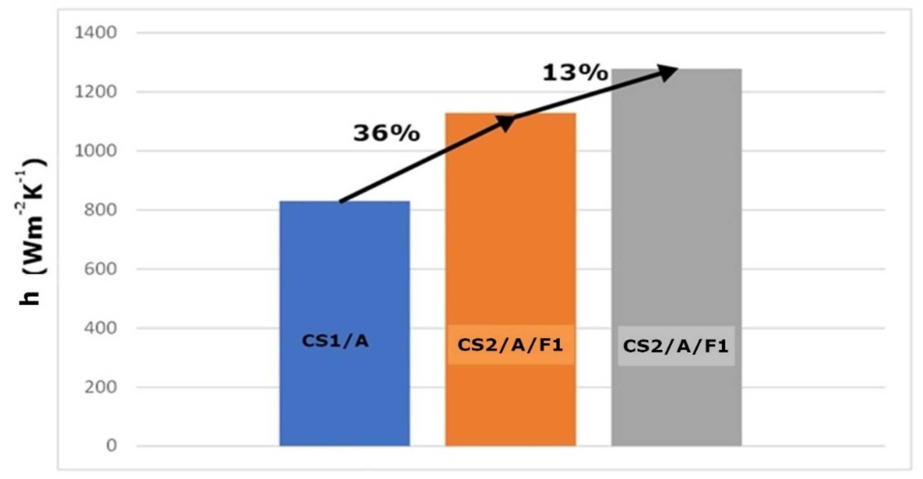
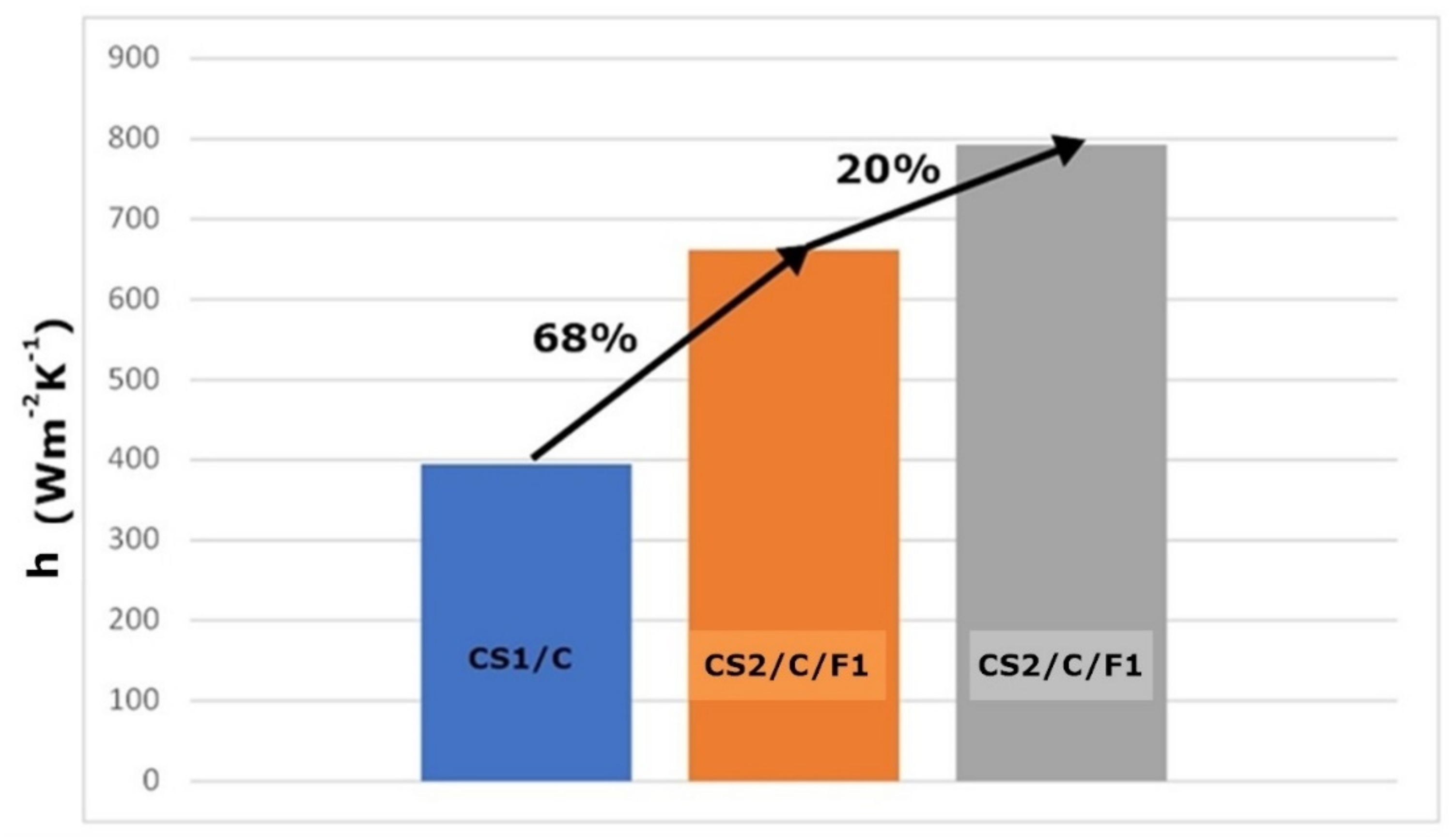
| Inner Pipe Water Flow | h (W m−2 K−1) | A (m2) | Estimated Length (m) |
| CS1/A | 830 | 1.6 | 51.1 |
| CS1/B | 526 | 2.7 | 85.6 |
| CS1/C | 395 | 3.8 | 121.7 |
| CS2/A/F1 | 1129 | 1.2 | 37.5 |
| CS2/B/F1 | 819 | 1.7 | 54.9 |
| CS2/C/F1 | 662 | 2.3 | 72.6 |
| CS2/A/F2 | 1278 | 1.0 | 33.1 |
| CS2/B/F2 | 962 | 1.5 | 46.8 |
| CS2/C/F2 | 793 | 1.9 | 60.7 |
| Case Study | ||
|---|---|---|
| Inner Pipe Water Flow | Estimated Length (m) | ΔP (Pa) |
| CS1/A | 51.1 | 35,799 |
| CS1/B | 85.6 | 59,969 |
| CS1/C | 121.7 | 85,260 |
| CS2/A/F1 | 37.5 | 26,272 |
| CS2/B/F1 | 54.9 | 38,462 |
| CS2/C/F1 | 72.6 | 50,862 |
| CS2/A/F2 | 33.1 | 23,189 |
| CS2/B/F2 | 46.8 | 32,787 |
| CS2/C/F2 | 60.7 | 42,525 |
Publisher’s Note: MDPI stays neutral with regard to jurisdictional claims in published maps and institutional affiliations. |
© 2022 by the authors. Licensee MDPI, Basel, Switzerland. This article is an open access article distributed under the terms and conditions of the Creative Commons Attribution (CC BY) license (https://creativecommons.org/licenses/by/4.0/).
Share and Cite
Firfiris, V.K.; Kalamaras, S.D.; Martzopoulou, A.G.; Fragos, V.P.; Kotsopoulos, T.A. Improvement of the Performance of an Earth to Air Heat Exchanger for Greenhouse Cooling by the Incorporation of Water Finned Tubes—A Theoretical Approach. AgriEngineering 2022, 4, 190-206. https://doi.org/10.3390/agriengineering4010014
Firfiris VK, Kalamaras SD, Martzopoulou AG, Fragos VP, Kotsopoulos TA. Improvement of the Performance of an Earth to Air Heat Exchanger for Greenhouse Cooling by the Incorporation of Water Finned Tubes—A Theoretical Approach. AgriEngineering. 2022; 4(1):190-206. https://doi.org/10.3390/agriengineering4010014
Chicago/Turabian StyleFirfiris, Vasileios K., Sotirios D. Kalamaras, Anastasia G. Martzopoulou, Vassilios P. Fragos, and Thomas A. Kotsopoulos. 2022. "Improvement of the Performance of an Earth to Air Heat Exchanger for Greenhouse Cooling by the Incorporation of Water Finned Tubes—A Theoretical Approach" AgriEngineering 4, no. 1: 190-206. https://doi.org/10.3390/agriengineering4010014
APA StyleFirfiris, V. K., Kalamaras, S. D., Martzopoulou, A. G., Fragos, V. P., & Kotsopoulos, T. A. (2022). Improvement of the Performance of an Earth to Air Heat Exchanger for Greenhouse Cooling by the Incorporation of Water Finned Tubes—A Theoretical Approach. AgriEngineering, 4(1), 190-206. https://doi.org/10.3390/agriengineering4010014