Article

Concept for an Electromechanical Connection and Steering Joint for a Small Off-Road Electric Vehicle

Faculty of Mechanical Engineering, University of Žilina, 010 26 Žilina, Slovakia
*
Authors to whom correspondence should be addressed.
Vehicles 2025, 7(2), 30; https://doi.org/10.3390/vehicles7020030
Submission received: 17 February 2025 / Revised: 18 March 2025 / Accepted: 24 March 2025 / Published: 27 March 2025

Abstract

:
Electrification and modularity are emerging as key trends in off-road vehicle development, prompting the need for innovative solutions in steering and modular coupling. This study presents an electromechanical connection and steering joint, conceived to replace traditional hydraulic systems and offer enhanced steering precision, modular adaptability, and system efficiency. By eliminating hydraulic components, the design reduces fluid leakage risks, lowers maintenance requirements, and improves energy integration with the vehicle’s electric drivetrain. The joint enables independent module articulation, including steering and controlled tilting, to optimize vehicle stability across diverse terrains. A prototype was built and tested under real-world conditions, assessing functional reliability, ease of integration, and operational performance. The findings demonstrate that electromechanical steering substantially boosts system flexibility compared to conventional hydraulic setups.

1. Introduction

Electric vehicles (EVs) deliver significant environmental benefits by reducing greenhouse gas (GHG) emissions, air pollution, and noise in urban and sensitive areas. With a potential CO2 emission reduction of 30–50% compared to internal combustion engine vehicles (ICEVs)—especially when powered by renewable energy—EVs also decrease fossil fuel dependence and enhance energy efficiency. Their zero-emission operation mitigates health risks and improves the overall operational performance. In off-road applications such as construction and agriculture, precise control of electric drivetrains and regenerative braking systems [1,2,3] boosts productivity and adaptability, although the total environmental impact depends on the electricity mix and the full vehicle lifecycle, including battery production and recycling [4,5,6,7].
Despite these advantages, off-road electrification introduces technical challenges. Traction motors and batteries must be robust enough to withstand vibrations, impacts, water, and dust [8,9,10], while variable loads and harsh terrains impose high demands on system reliability [1]. Furthermore, limited battery life and the need for advanced battery management escalate operational expenses and complicate maintenance [3,11,12,13].
The design of electromechanical steering systems is crucial for overcoming these challenges. Optimized steering enhances energy efficiency and reduces emissions in construction machinery [14,15,16] while improving maneuverability and safety in demanding work environments. In off-road conditions, precise electric steering combined with regenerative braking provides notable control advantages [9,10,14,17]. Recent research has demonstrated that steering shaft parameters, such as the universal joint’s phase angle and initial steering shaft inclination, significantly influence vehicle handling and stability. The optimization of these parameters can markedly improve steering responsiveness, reduce vibrations, and enhance overall maneuverability, especially in challenging off-road conditions [18]. The latest research findings indicate that adjusting the steering axis inclination can enhance dynamic stability and significantly reduce the “snaking effect,” characterized by unwanted oscillations between articulated vehicle modules. The optimal design of this parameter, thus, contributes to improved handling and safety in challenging off-road conditions [19].
Moreover, recent studies emphasize the benefits of integrating human intervention into autonomous steering systems through reinforcement learning methods. Incorporating inputs from experienced drivers accelerates model convergence, overcomes local optima, and enhances overall vehicle safety, especially in complex and demanding off-road scenarios [20].
Articulated vehicles, which employ a central joint mechanism for steering, offer exceptional maneuverability and traction—making them ideal for construction, forestry, and mining applications [21,22]. Various articulated joint technologies exist: hydraulically controlled joints [22,23] offer high force transmission but can suffer from instability at high speeds; electro-hydraulic systems [21] integrate sensors for enhanced precision; and mechanical joints with fixed damping [24] provide reduced wear and greater flexibility. Current research addresses issues such as dynamic instability, the “snaking effect,” hydraulic pressure losses, and weight reduction [21,22,23,25,26].
Modularity further enhances vehicle design by enabling component interchangeability across battery-electric, hybrid, and fuel cell platforms, thereby reducing manufacturing costs and improving sustainability [27,28,29]. Standardized interfaces are essential for compatibility, though additional testing may extend development cycles [30]. In summary, integrating advanced electric drivetrains, robust steering systems, and modular design principles offers a promising path toward cleaner, more efficient, and adaptable vehicles. Addressing the remaining technical challenges through focused research and innovation is essential for unlocking the full potential of these technologies in both urban and off-road environments.
The project aims to design a universal, lightweight off-road vehicle with electric wheel drive, predominantly constructed from unconventional lightweight materials. Such a vehicle could serve mountain rescue units, firefighters, hunters, conservationists, farmers, vintners, and forest managers, potentially replacing the existing ATVs or UTVs powered primarily by combustion engines. The electric drivetrain provides quiet operation, which benefits both the driver and the surrounding environment, especially relevant in natural areas such as national parks or conservation zones. The vehicle’s universality is rooted in its modular design, allowing configuration according to end-user needs.

2. Materials and Methods

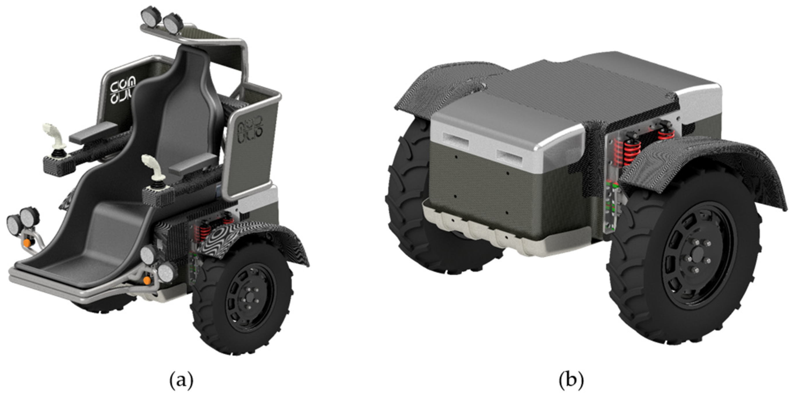
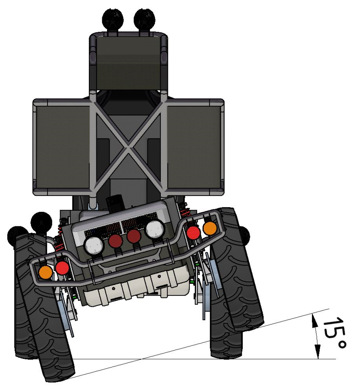
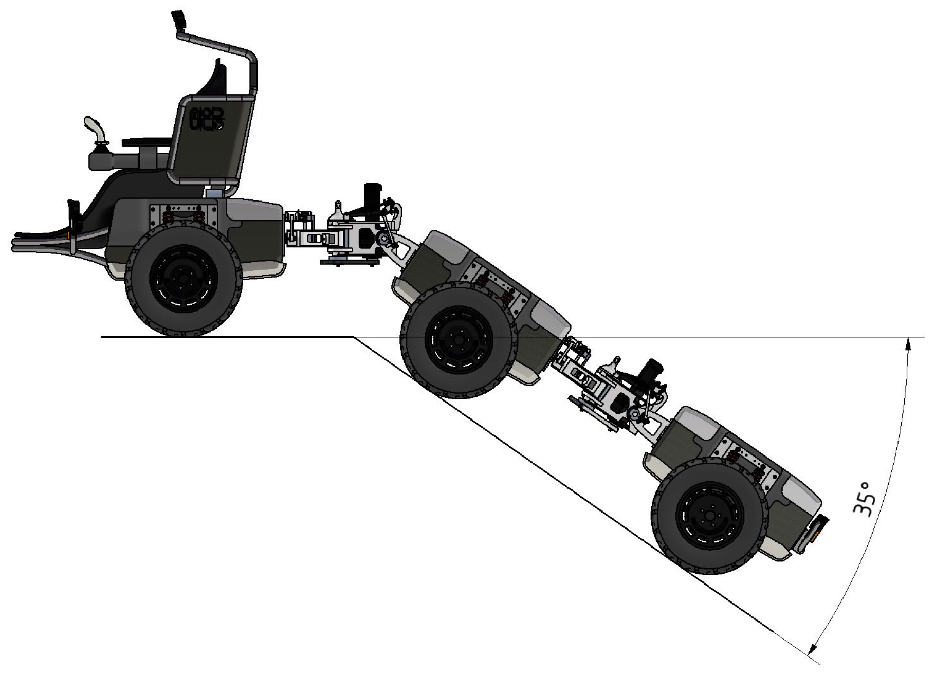
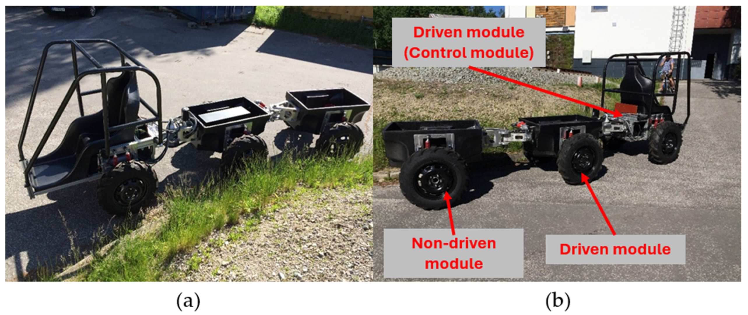
2.1. Design of a Small Off-Road Electric Vehicle

The small off-road electric vehicle MODULO consists of three main components called modules. By combining these modules, various vehicle configurations with four to six wheels can be created depending on their intended use. The basic modules are mechanically and electrically compatible with each other and can be combined in different ways to meet the needs of the end user.
The first main component is the control module shown in Figure 1a. The control module is designed as a monocoque made of carbon composite. This module includes the driver’s seat along with steering components (joysticks for controlling the vehicle’s direction), a protective driver frame, lighting, and two drive axles with wheels, which house the wheel motors. The interior of the module is equipped with control electronics, a traction battery, and inverters. Although the control module contains the driver’s seat and components for operating the vehicle, the vehicle can also be controlled remotely. This method of operation is particularly suitable when the vehicle is working in extremely challenging or sloped terrain where the driver’s safety could potentially be at risk.
The second main component is the standard module (Figure 1b). This module can function as either a powered (driven) unit or a passive (non-driven) unit. In the non-driven configuration, the carbon monocoque includes wheel axles and wheels on both sides but contains no motors. For the driven configuration, traction batteries, inverters, and control electronics are integrated inside the module, and the axles are fitted with electric wheel motors.
The third main component is the electromechanical connection and steering joint, whose design and arrangement variants are described in the following text.

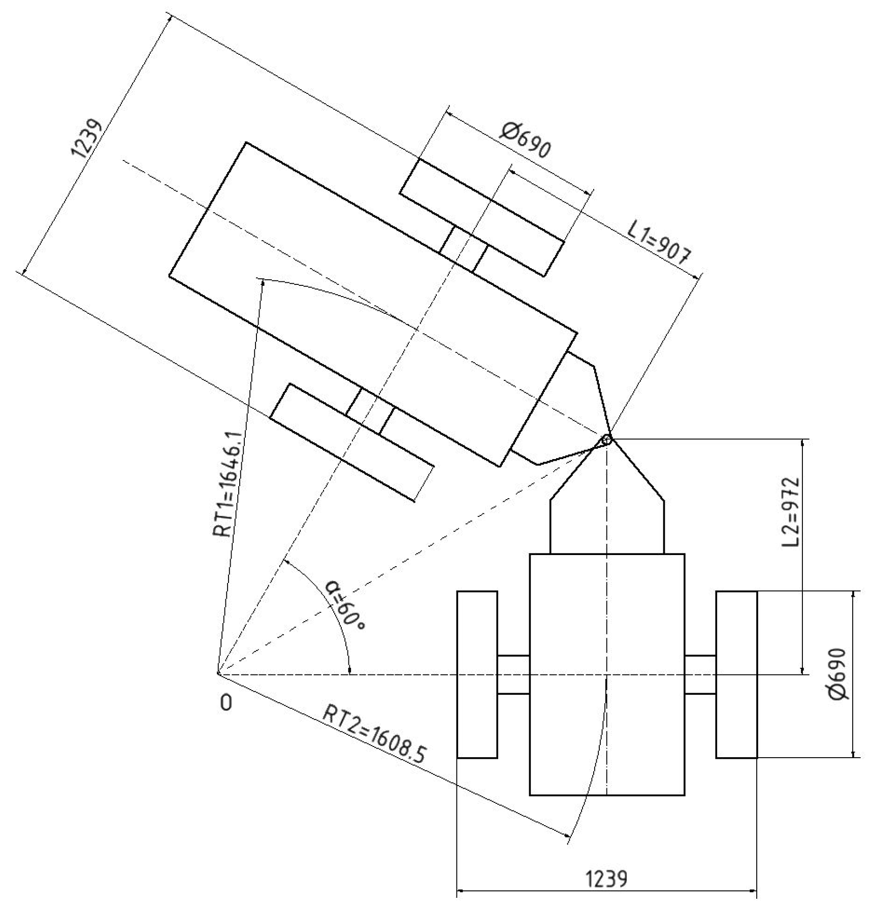
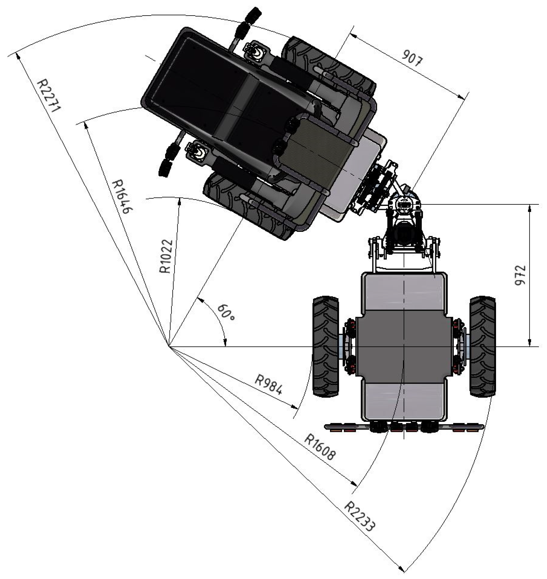
2.2. Requirements for the Design of the Electromechanical Connection and Steering Joint

The proposed electromechanical connection and steering joint are primarily intended for the small off-road electric vehicle MODULO. The most important structural and functional requirements for this steering joint are as follows:
  • Mechanical connection of two standard modules or the connection of a control module and a standard module;
  • Steering the vehicle’s direction by rotating the joint. The joint rotation must be achieved electrically using a servo drive and additional reduction gears;
  • Powering the steering servo drive from the vehicle’s traction batteries;
  • Ensuring sufficient space in the proposed design for housing the steering servo drive and routing electrical cables to the servo drive;
  • Enabling the mutual lateral tilt of two connected modules;
  • Enabling the mutual longitudinal tilt of two connected modules;
  • Modular construction, allowing the arrangement of the connection and steering joint to be customized according to the needs of the end user.
Despite the numerous advantages of hydraulic steering systems, it was decided that an electric system would be used for steering actuation. For a modular electric vehicle, the use of a unified power system for all the components offers significant benefits. The absence of hydraulic systems allows the saved space to be utilized for increasing battery capacity or reducing the overall size of the module. Additionally, this design choice eliminates the risk of hydraulic fluid leaks, which can have negative environmental impacts [31,32,33,34].

2.3. Concept Development

As part of the project aimed at developing a universal lightweight off-road vehicle with electric wheel drive, it was necessary to design a system for steering control and a coupling mechanism between vehicle modules. Based on the requirements summarized in Section 2.2, four conceptual design variants were developed.
The first variant was inspired by a simple, widely used mechanical connection method typically employed between a vehicle and a trailer. It utilized a standard towing coupling, where one module featured a tow ball and the other a tow bar with a matching ball coupling. The primary advantages of this approach included the use of standardized components and a relatively large range of motion between the connected modules. However, this variant did not address vehicle steering control or electrical interconnection between modules; it merely provided a passive connection, with one module effectively being towed as a trailer.
A second coupling variant utilizing a joint system interconnected by pivot pins was designed (Figure 2). This system enabled rotational freedom around all three axes, with the option to lock the pivots to restrict movement as needed. Unlike the first variant, it allowed for the controlled limitation of rotation in specific directions. However, similarly to the first variant, it did not include steering functionality or electrical interconnection between modules, functioning solely as a mechanical coupling with the added advantage of selectively locking rotations.
The third proposed variant involved using a slewing bearing mounted atop the vehicle modules (Figure 3), with modules connected through their superstructures. Steering would be provided by a servomotor, transferring torque via a geared transmission onto the slewing bearing. However, this design had several notable drawbacks, including significantly increased vehicle height, considerable additional weight due to the bearing, inability for mutual transverse and longitudinal tilting between connected modules, and overall mechanical complexity. These limitations negatively affected the suitability of this variant for demanding off-road applications.
The fourth variant, presented in this article, involves a modular steering and connection joint designed to link two vehicle modules and control their steering using a servomotor and gearing mechanism. The primary functions of steering and module coupling were enhanced by additional transverse and longitudinal tilting capabilities, improving vehicle stability, traction, and terrain adaptability by ensuring continuous wheel-ground contact. This solution is described in detail in the following sections.
All the proposed variants were evaluated according to various functional, structural, and operational criteria. The detailed results of this evaluation are summarized in the table provided in Supplementary Material.

2.4. Reflection on Developed Concepts

Among the four proposed module connection concepts, two focused solely on basic mechanical coupling—Concept 1 and Concept 2.
Concept 1 offered the clear advantage of simplicity and the use of standardized components. However, as previously mentioned, this concept addressed only the mechanical linkage between modules, with one module effectively being towed as a trailer. Within the MODULO vehicle project, this solution would be suitable for mechanically attaching a third non-driven standard module, where electrical connections and inter-module steering are unnecessary.
The ball joint connection used in this design would provide significant benefits in rough terrain, allowing the attached module to effectively adapt to surface irregularities in both transverse and longitudinal directions [35,36]. However, in highly uneven terrain with unstable surfaces such as mud, wet grass, or snow, these advantages could turn into drawbacks. If the attached module lost wheel traction, it could uncontrollably slide, potentially leading to collisions with other modules or negatively impacting the stability of the entire vehicle.
Concept 2 (Figure 2) utilizes a joint system with rotatable pivot pins, which can be locked to restrict movement. This partially mitigates the drawbacks of Concept 1, as locking the joints prevents the uncontrolled movement of the attached module in cases where its wheels lose traction on unstable terrain.
However, this approach has a notable disadvantage—locking any of the three tilting axes reduces the module’s ability to adapt to terrain irregularities, potentially resulting in worsened handling and reduced off-road capability. Another drawback is that the locking mechanism must be activated in advance before entering unstable terrain, placing higher operational demands on the vehicle’s operator.
Concept 3 features a slewing bearing mounted at the top of the module, differing from the first two concepts by actively addressing vehicle steering. Its primary advantage is the ability to control the driving direction via a servo motor. However, this concept presents several major drawbacks. The most critical limitation is the need to connect two modules through their superstructures, which eliminates the possibility of transverse or longitudinal tilting between the connected modules. As a result, the two modules function as a single rigid unit with both axles steering simultaneously, making this design unsuitable for off-road applications. It could be viable for vehicles operating on relatively flat surfaces, such as AGV transport systems, where module articulation is not required [37,38].
Another significant drawback for the MODULO vehicle is the considerable increase in the overall vehicle height due to the placement of the slewing bearing. This height increase would negatively affect the vehicle’s center of gravity, reducing stability when driving on steep lateral inclines.
The fourth steering concept relocates the entire steering mechanism between the modules, providing both mechanical coupling and directional control. This design is based on the conventional articulated steering system, commonly used in off-road machinery such as dump trucks and front loaders [24].
For the MODULO vehicle, this concept has been enhanced with transverse and longitudinal tilting capabilities between modules. Unlike Concept 3, this eliminates the need for superstructure connections, preserving modular flexibility. Additionally, this approach does not significantly increase vehicle height; on the contrary, its design lowers the vehicle’s center of gravity, improving stability.
The end-stop locking mechanism for tilting movement allows the modules to adapt to terrain variations while preventing uncontrolled module movement in difficult conditions, such as rough terrain with unstable surfaces. This ensures that the vehicle maintains optimal stability and traction control in demanding off-road environments.
The proposed module connection and steering concepts for the MODULO vehicle were developed progressively, starting from the simplest alternatives and evolving into more advanced solutions. Each subsequent concept aimed to eliminate the shortcomings identified in the previous designs. This iterative approach led to the fourth and final concept, which successfully addressed all the previously observed limitations, resulting in a comprehensive and optimized solution.

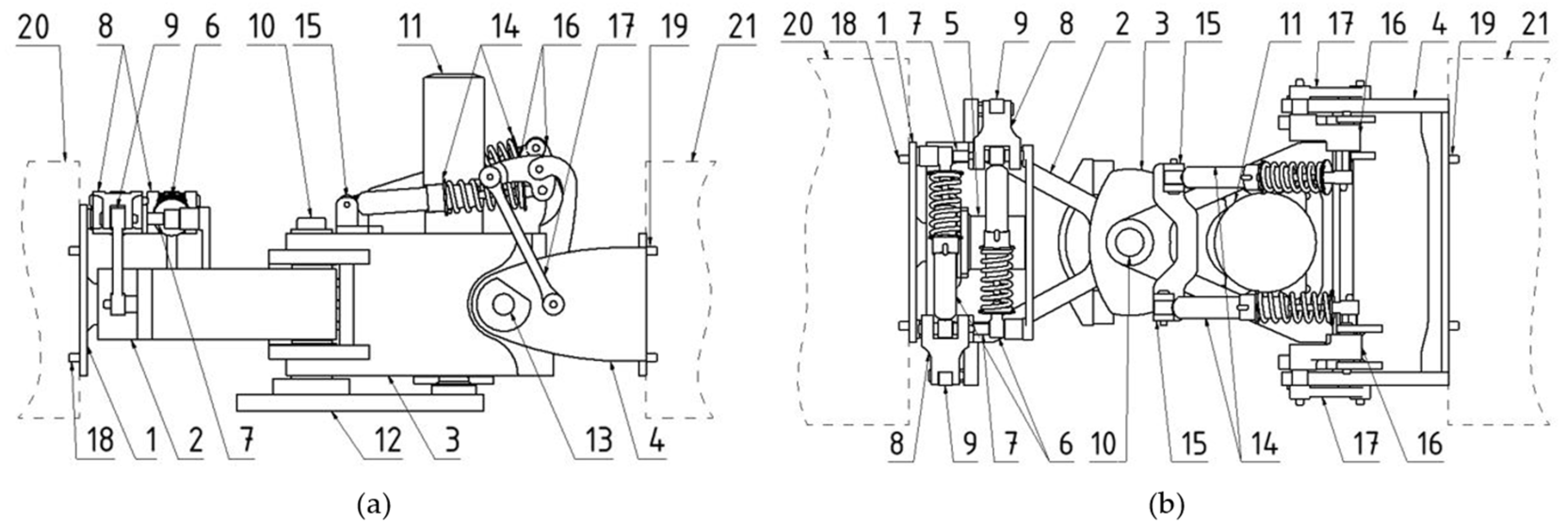
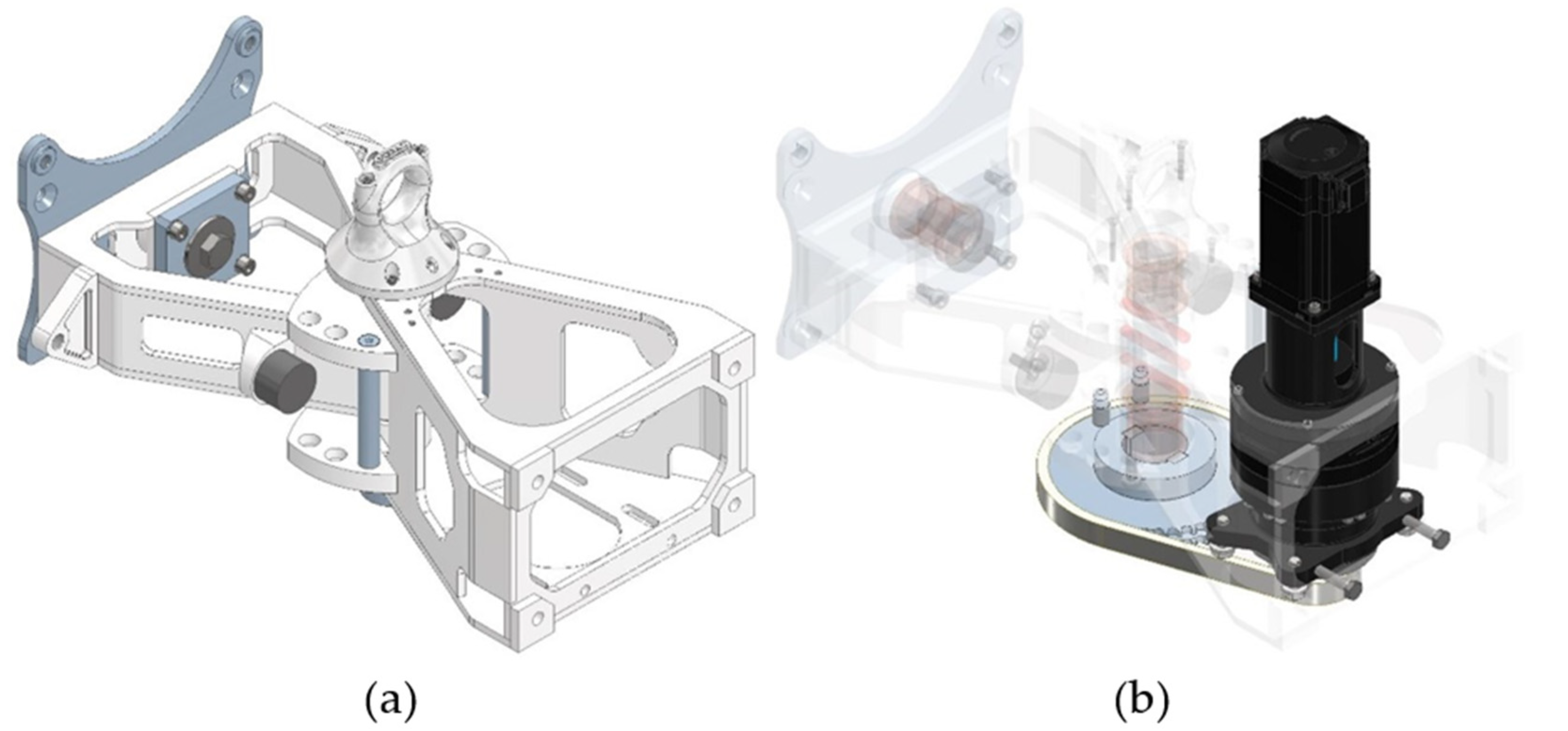
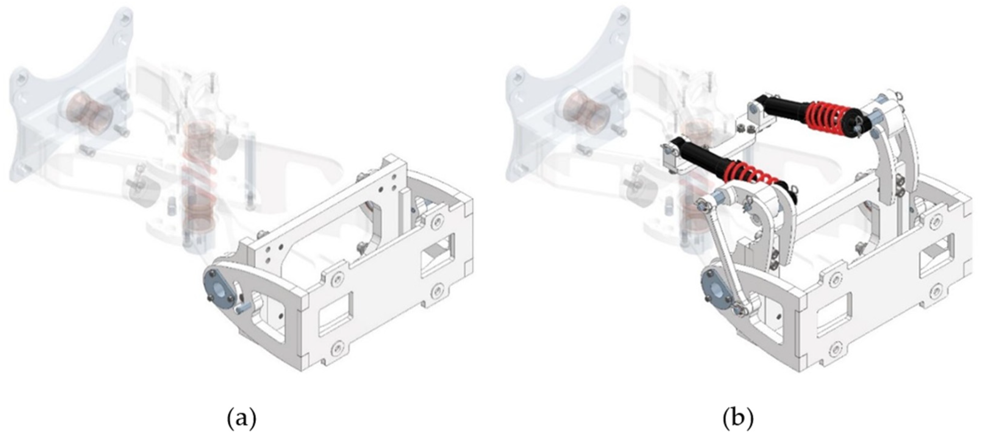
2.5. Design of the Electromechanical Connection and Steering Joint

Figure 4 shows a schematic representation of the connection and steering joint in both side and top views, with numerical labels indicating the main components.
The electromechanical connection and steering joint with tilting in two planes consists of a rotating plate (1) with a pin (5), a towing frame (2), a steering frame (3), and a tilting frame (4). The rotating plate (1) is connected to the control module (20) using screw joints (18), while the tilting frame (4) is attached to the standard module (21) using screw joints (19). The rotating plate (1) is pivotally connected to the towing frame (2) through a pin (5), enabling the mutual lateral tilting of these two components. The damping and suspension of the lateral tilting are provided by a system of two spring-dampers (6), mounted at one end on pins (7) of the rotating plate and at the other end on rockers (8) of the linkage (9) connected to the towing frame (2). The towing frame (2) houses a central pin (10), which is pivotally mounted in the steering frame (3). Steering is performed by an electric motor with a gearbox (11) located in the steering frame (3). The electric motor with the gearbox (11) rotates the central pin (10) via a chain drive (12), enabling mutual rotation between the towing frame (2) and the steering frame (3). The connection between the steering frame (3) and the tilting frame (4) is realized through a pivot pin (13), which is fixed in the tilting frame (4) and rotates in the steering frame (3). This connection allows mutual longitudinal tilting of these two components. The damping and suspension of the longitudinal tilting are ensured by a system of two spring-dampers (14), mounted at one end on brackets (15) of the steering frame (3) and at the other end on rockers (16) of the linkage (17) connected to the tilting frame (4).
The majority of the components in the electromechanical connection and steering joint are made from aluminum alloy EN AW 6060. The rotating plate, pins, and other highly stressed parts of the structure are manufactured from various types of alloyed steels.
The steering system utilizes a Leadshine CS-M234120 (Made by Shenzhen Leadshine Technology Co., Shenzhen, China) stepper motor, which is connected to a Spinea DS-140-115 (Made by Spinea s.r.o., Prešov, Slovakia) cycloidal gearbox. The Spinea cycloidal gearbox was selected due to its compact dimensions (diameter: 150 mm, length: 85 mm) and high gear ratio of iCp = 115. Another crucial parameter was the backlash, which for this gearbox is less than 1 arcmin. The gearbox operates with an efficiency of ηCp = 0.86. The minimal backlash is a key factor in ensuring the necessary steering precision and rigidity [39,40,41,42,43]. The torque from the gearbox output is transmitted to the steering pin through a chain drive. The driving sprocket on the cycloidal gearbox has 19 teeth, while the driven sprocket on the steering pin has 50 teeth. The gear ratio of the chain drive is iRp = 2.632. The maximum torque of the stepper motor MM is 12 Nm.
The overall steering gear ratio iC:
iC = iCp × iRp
where iCp is the overall gear ratio of the cycloidal gearbox and iRp is the gear ratio of the chain drive. The value of the overall steering gear ratio is iC = 302.68.
Maximum steering torque MRmax:
MRmax = MM × iC × ηCp × ηRp
where MM (12 Nm) is the maximum torque of the motor, iC is the overall steering gear ratio, and ηCp (86%) is the efficiency of the Spinea cycloidal gearbox, while ηRp (98%) is the efficiency of the chain drive. The maximum steering torque MRmax is 3060 Nm.
The steering angle in the direction of the vehicle’s movement can reach up to ±60 degrees. This angle can be limited to ±42 degrees or ±21 degrees using adjustable stops. If necessary, the steering can additionally be locked in the neutral position either with fixed locking screws or flexibly using stop rubber mounts.
Calculation of the turning radius for the front (steering) module at the maximum steering angle of 60 degrees:
R T 1 = L 2 cos α + L 1 tan α = 972 cos 60 ° + 907 tan 60 ° = 1646.029   m m
Calculation of the turning radius for the rear (basic) module at the maximum steering angle of 60 degrees:
R T 1 = L 1 cos α + L 2 tan α = 907 cos 60 ° + 972 tan 60 ° = 1608.498   m m
Both calculated radii are depicted in the schematic shown in Figure 5.
Figure 6 illustrates the vehicle at its maximum steering angle of 60 degrees. The diagram includes the dimensioning of the axle distances from the turning axis and the fundamental turning radii of individual wheels in the 4 × 4 configuration.
The mutual lateral tilt of two consecutive modules can reach a maximum value of ±15 degrees, or it can be limited to ±7 degrees using an adjustable stop. If necessary, the lateral tilt mechanism can be locked in the neutral position. The lateral tilt can operate with suspension using spring-dampers or without this suspension. The application of additional damping is anticipated when driving at higher speeds on uneven terrain.
Figure 7 depicts and dimensions the maximum transverse tilt between two modules (in this case, the steering and standard modules).
The longitudinal tilt of two consecutive modules can reach a maximum value of ±35 degrees, or it can be limited to ±17 degrees using an adjustable stop. If necessary, the longitudinal tilt mechanism can be locked in the neutral position. The longitudinal tilt can operate with suspension using spring-dampers or without this suspension. The application of additional damping is anticipated when driving at higher speeds on uneven terrain.
Figure 8 illustrates and dimensions the maximum achievable longitudinal tilt. In this case, the vehicle is configured as a 6 × 4 version with one steering module and two standard modules. The steering and standard modules are connected using suspension variant 12 (Table 1), while the standard modules are linked by suspension variant 7 (Table 1).
Just like the MODULO vehicle itself, the electromechanical connection and steering joint consist of several interchangeable modules that can be combined in various ways. By configuring these modules, up to sixteen different arrangements of the electromechanical steering and coupling joint can be achieved (Table 1). The final configuration depends on the intended application of the vehicle and the specific requirements of the end user.
The electromechanical connection and steering joint consists of the following modules:
  • Base Module: It is the main connecting element of two standard vehicle modules. It is also the supporting module to which all the other modules are attached.
  • Steering Module: Composed of a motor assembly with a cycloidal gearbox and a chain drive. It serves to control the direction of the vehicle.
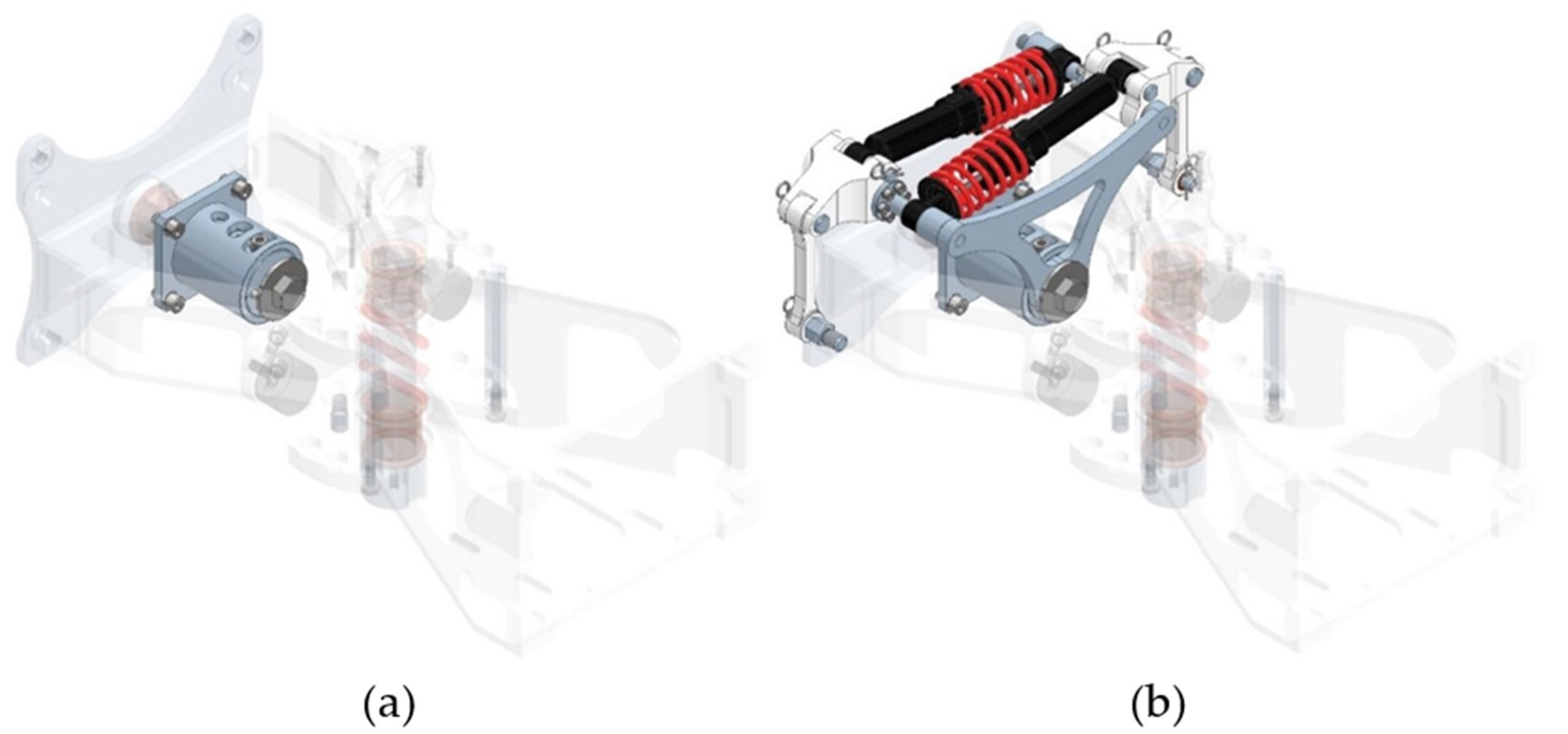
  • Lateral Tilt Module: Allows the mutual lateral tilting of two consecutive standard vehicle modules.
  • Lateral Tilt Damping Module: An additional module for the lateral tilt module. It serves to dampen shocks from lateral tilting. Its use is particularly beneficial when driving at higher speeds on uneven terrain.
  • Longitudinal Tilt Module: Allows the mutual longitudinal tilting of two consecutive standard vehicle modules.
  • Longitudinal Tilt Damping Module: An additional module for the longitudinal tilt module. It serves to dampen shocks from longitudinal tilting. Its use is particularly beneficial when driving at higher speeds on uneven terrain.
Figure 9, Figure 10 and Figure 11 illustrate the individual modules of the electromechanical coupling and steering joint along with their position relative to the adjacent modules.
Figure 9a shows the basic module, while Figure 9b depicts the steering module and its positioning relative to the basic module.
Figure 10a shows the lateral tilting module, while Figure 10b illustrates the lateral tilting modules and their positioning relative to the basic module.
Figure 11a presents the longitudinal tilting module, while Figure 11b illustrates the longitudinal tilting damping module along with their placements in relation to the basic module. The real prototype from Figure 11b can be seen in Figure 12b.

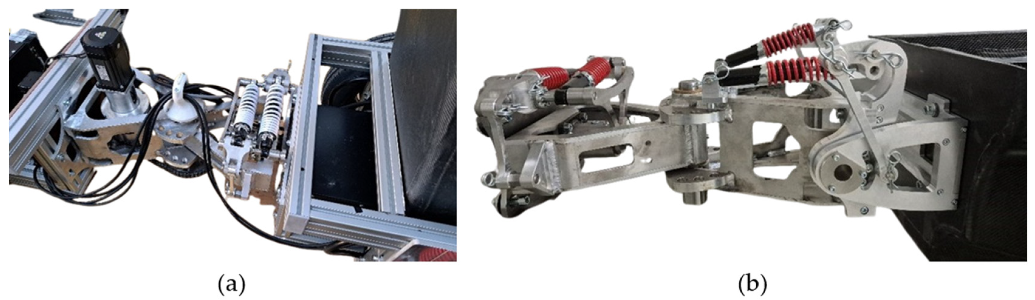
3. Prototype Manufacturing
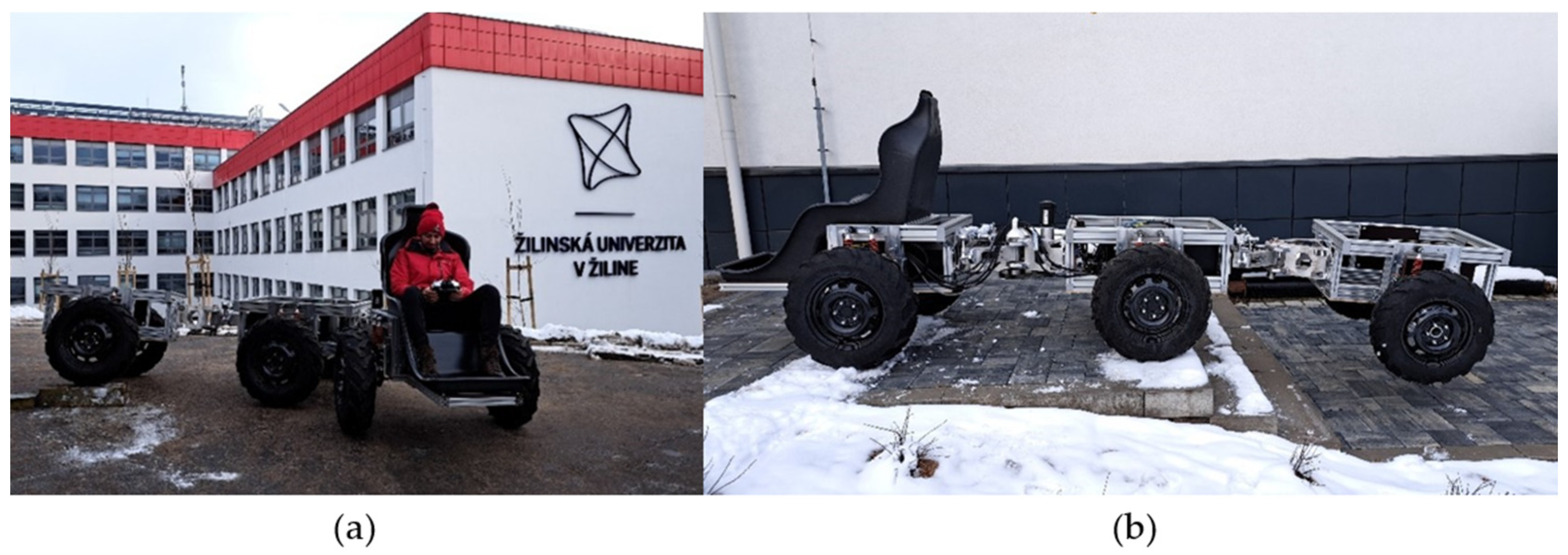
Based on the aforementioned design, developed in a CAD system, manufacturing documentation was created, leading to the production of a prototype electromechanical connecting and steering joint. As part of the prototype manufacturing process, the following components were produced: two basic modules, one steering module, two transverse tilting modules, two transverse tilting damping modules, one longitudinal tilting module, and one longitudinal tilting damping module. These modules were then assembled into variant 8 and variant 7 (Table 1).
The assembled prototype electromechanical coupling and steering joints (Figure 12a) were used to connect the first prototype vehicle modules. Configuration 8 connected a steering module to a standard module, while Configuration 7 connected two standard modules. This assembly resulted in a vehicle featuring a 6 × 4 wheel configuration.
Later, the prototype standard vehicle modules were replaced with monocoques made of composite materials. In this version, variant 8 was used to connect the steering module to a standard module, while variant 11 was implemented to link two standard modules. This setup maintained the 6×4 drivetrain layout, ensuring optimal performance and stability.

4. Driving Tests

The driving tests were conducted within the premises of the University of Žilina in Žilina. During the tests, performed on both paved roads and uneven, unpaved terrain, the functionality of the individual modules of the electromechanical coupling and steering joint was evaluated. Figure 13 presents footage from the first driving tests.
The initial driving tests were carried out using a prototype steering module and two prototype standard vehicle modules. The vehicle configuration and module connections are described in the Prototype Manufacturing Section.
During these tests, the functionality and structural integrity of the individual modules of the electromechanical connecting and steering joint were evaluated. Adjustments were made to the steering angle settings and the transverse tilting angles. The locking mechanisms of individual modules were also tested, with a particular focus on the accessibility of adjustment and locking components. The tests provided insights into when and under what conditions it is appropriate—or inappropriate—to modify the tilt angle settings.
Subsequently, the two prototype standard modules were replaced with composite monocoque modules. At this stage of the project, electromechanical connecting joints were implemented in variant 8 and variant 11. Variant 8 connected the steering module to a standard module, while variant 11 linked two standard modules. The second test runs are shown in Figure 14.
The tests also revealed minor issues in ergonomics and modularity, where certain components could not be disassembled or reassembled onto the joint as quickly as expected. This was particularly evident in the pin securing the outer damper in the rocker arm of the transverse tilting damping module, which could not be removed due to a collision between the pin head and the rotating plate during extraction. Another issue arose during the disassembly of the transverse tilting module, where an overly long bolt was used for mounting, making its insertion into the opening inconvenient for the operator. These shortcomings are currently being addressed, and in the next design iteration of the electromechanical connection and steering joint, the identified issues will be resolved.

5. Discussion

As part of the MODULO small off-road electric vehicle project, it was necessary to develop a steering system. Given the vehicle’s fully electric concept, an electric servomotor with additional gearing was selected as the basis for the steering mechanism. This principle was implemented into the electromechanical connecting and steering joint, designed to fulfill two primary functions: connecting the vehicle modules (steering module to a standard module, or standard to standard) and enabling steering control. In addition to these core requirements, further demands arose, including transverse and longitudinal tilting between the modules and ensuring the modularity of the joint configuration to align with the modular concept of the entire vehicle.
Based on these specified requirements, a conceptual design of the electromechanical connection and steering joint was developed using the Inventor 2024 CAD software. This design was further refined into manufacturing documentation, which facilitated the production of the first prototype modules of the joint. Once manufactured, these modules were assembled into two separate electromechanical connections and steering joints, arranged in two different configurations. These joints were then installed on the MODULO prototype vehicle.
Following the assembly of the vehicle, initial tests of the electromechanical coupling and steering joints were conducted to validate their primary function—vehicle steering control. Additionally, other functionalities, such as transverse and longitudinal tilting, were tested. The results confirmed the overall functionality of the joint, while revealing minor shortcomings related to ergonomics during adjustment and disassembly, as well as modularity. However, these issues did not affect the joint’s overall performance.
The next phase of the project will focus on eliminating the identified assembly issues. The development of a new prototype will aim to reduce the weight and dimensions of the joint by utilizing motion and structural simulations, as well as topological optimization. As shown in Figure 12a, the electrical cables are currently exposed, posing a risk of damage or entanglement with obstacles in off-road conditions. The new prototype must incorporate a secure cable routing system to prevent these issues. Additionally, the implementation of a flexible protective casing is recommended to shield the joint from external damage while also ensuring operator safety by preventing injuries from moving components. Following the completion of the improved prototype, more extensive and complex tests, primarily focused on driving performance under various operational and terrain conditions, will be conducted.

6. Conclusions

As a part of the MODULO small off-road electric vehicle project, a steering system had to be developed. Given the vehicle’s fully electric design, an electric servomotor with additional gearing was chosen as the foundation of the steering mechanism. This principle was implemented into the electromechanical coupling and steering joint, designed to fulfill two primary functions: connecting vehicle modules (steering module to a standard module, or standard to standard) and enabling steering control. Beyond these core requirements, additional demands emerged, including transverse and longitudinal tilting between modules and ensuring the modularity of the joint’s configuration in alignment with the vehicle’s modular design concept.
Based on these specified requirements, a conceptual design of the electromechanical coupling and steering joint was developed using the CAD software. This design was further refined into manufacturing documentation, enabling the production of the first prototype joint modules. After fabrication, two separate electromechanical coupling and steering joints were assembled in two different configurations and subsequently installed on the MODULO prototype vehicle.

7. Patents and Utility Models

The proposed solution for the electromechanical coupling and steering joint is protected by Utility Model No. 153-2022: Electromechanical Steering Joint with Tilting in Two Planes.

Supplementary Materials

The following supporting materials can be downloaded at: https://www.mdpi.com/article/10.3390/vehicles7020030/s1, Table S1: Device for interconnecting individual vehicle modules.

Author Contributions

Conceptualization, T.G. and I.G.; methodology, I.G.; software, R.M.; validation, I.G., R.M., and M.V.; formal analysis, M.V.; investigation, M.V.; resources, M.V.; data curation, M.V.; writing—original draft preparation, T.G.; writing—review and editing, T.G. and M.V.; visualization, T.G.; supervision, T.G.; project administration, I.G.; funding acquisition, T.G. All authors have read and agreed to the published version of the manuscript.

Funding

This research was funded by the Slovak Research and Development Agency, grant numbers APVV-18-0457 and APVV-22-0423.

Data Availability Statement

The data presented in this study are available upon request from the corresponding author due to privacy restrictions.

Acknowledgments

This article was created in the context of the project KEGA 027ŽU-4/2024 supported by the Ministry of Education, Research, Development and Youth of the Slovak Republic.

Conflicts of Interest

The authors declare no conflicts of interest.

References

  1. Wu, J.; Wang, G.; Zhao, H.; Sun, K. Study on electromechanical performance of steering of the electric articulated tracked vehicles. J. Mech. Sci. Technol. 2019, 33, 3171–3185. [Google Scholar]
  2. Trancossi, M.; Pascoa, J.; Xisto, C. Design of an innovative off road hybrid vehicle by energy efficiency criteria. Int. J. Heat Technol. 2016, 34, S387–S395. [Google Scholar]
  3. Tong, Z.-M.; Miao, J.-Z.; Li, Y.-S.; Tong, S.-G.; Zhang, Q.; Tan, G.-R. Development of electric construction machinery in China: A review of key technologies and future directions. J. Zhejiang Univ. Sci. A 2021, 22, 245–264. [Google Scholar]
  4. Wei, F.; Walls, W.; Zheng, X.; Li, G. Evaluating environmental benefits from driving electric vehicles: The case of Shanghai, China. Transp. Res. Part D Transp. Environ. 2023, 119, 103749. [Google Scholar] [CrossRef]
  5. Ajanovic, A.; Haas, R. On the environmental benignity of electric vehicles. J. Sustain. Dev. Energy Water Environ. Syst. 2019, 7, 416–431. [Google Scholar] [CrossRef]
  6. Ivković, N. An Analysis of the Environmental Impact of Electric Vehicles. Put I Saobraćaj 2022, 68, 43–50. [Google Scholar]
  7. Hawkins, T.R.; Gausen, O.M.; Strømman, A.H. Environmental impacts of hybrid and electric vehicles—A review. Int. J. Life Cycle Assess. 2012, 17, 997–1014. [Google Scholar]
  8. Hernandez, M.; Messagie, M.; Hegazy, O.; Marengo, L.; Winter, O.; Van Mierlo, J. Environmental impact of traction electric motors for electric vehicles applications. Int. J. Life Cycle Assess. 2017, 22, 54–65. [Google Scholar]
  9. Ghobadpour, A.; Monsalve, G.; Cardenas, A.; Mousazadeh, H. Off-road electric vehicles and autonomous robots in agricultural sector: Trends, challenges, and opportunities. Vehicles 2022, 4, 843–864. [Google Scholar] [CrossRef]
  10. Un-Noor, F.; Wu, G.; Perugu, H.; Collier, S.; Yoon, S.; Barth, M.; Boriboonsomsin, K. Off-road construction and agricultural equipment electrification: Review, challenges, and opportunities. Vehicles 2022, 4, 780–807. [Google Scholar] [CrossRef]
  11. Poullikkas, A. Sustainable options for electric vehicle technologies. Renew. Sustain. Energy Rev. 2015, 41, 1277–1287. [Google Scholar]
  12. Kim, Y.-H. Study on Modularization of Components for Cost Reduction of Sail Yacht Steering System. J. Ocean Eng. Technol. 2020, 34, 469–474. [Google Scholar] [CrossRef]
  13. He, X.; Jiang, Y. Review of hybrid electric systems for construction machinery. Autom. Constr. 2018, 92, 286–296. [Google Scholar]
  14. Huang, X.; Huang, Q.; Cao, H.; Yan, W.; Cao, L.; Zhang, Q. Optimal design for improving operation performance of electric construction machinery collaborative system: Method and application. Energy 2023, 263, 125629. [Google Scholar] [CrossRef]
  15. Lin, T.; Lin, Y.; Ren, H.; Chen, H.; Chen, Q.; Li, Z. Development and key technologies of pure electric construction machinery. Renew. Sustain. Energy Rev. 2020, 132, 110080. [Google Scholar]
  16. Quan, Z.; Ge, L.; Wei, Z.; Li, Y.W.; Quan, L. A survey of powertrain technologies for energy-efficient heavy-duty machinery. Proc. IEEE 2021, 109, 279–308. [Google Scholar]
  17. Huang, X.; Yan, W.; Cao, H.; Chen, S.; Tao, G.; Zhang, J. Prospects for purely electric construction machinery: Mechanical components, control strategies and typical machines. Autom. Constr. 2024, 164, 105477. [Google Scholar]
  18. Gao, J.; Qi, X. Handling performance analysis and optimization of a vehicle with considering the influence of steering shaft parameters. J. Mech. Sci. Technol. 2023, 37, 569–582. [Google Scholar]
  19. Skurjat, A. The effect of steering axis inclination on the dynamic stability of vehicles with an articulated steering. Sci. Rep. 2025, 15, 676. [Google Scholar]
  20. Shi, G.; Zhao, Q.; Wang, J.; Dong, X. Research on reinforcement learning based on PPO algorithm for human-machine intervention in autonomous driving. Electron. Res. Arch. 2024, 32. [Google Scholar] [CrossRef]
  21. Łopatka, M.J.; Rubiec, A. Concept and preliminary simulations of a driver-aid system for transport tasks of articulated vehicles with a hydrostatic steering system. Appl. Sci. 2020, 10, 5747. [Google Scholar] [CrossRef]
  22. Xu, T.; Shen, Y.; Huang, Y.; Khajepour, A. Study of hydraulic steering process for articulated heavy vehicles based on the principle of the least resistance. IEEE ASME Trans. Mechatron. 2019, 24, 1662–1673. [Google Scholar]
  23. Zhang, Q.; Wang, X.; Tong, Z.; Cheng, Z.; Liu, X. Experimental Study on Structure Optimization and Dynamic Characteristics of Articulated Steering for Hydrogen Fuel Cell Engineering Vehicles. World Electr. Veh. J. 2024, 15, 306. [Google Scholar] [CrossRef]
  24. Tesar, J.S.; Cohen, C.J.; Obermark, J. Articulated joint for a high-mobility modular vehicle. In Unmanned Ground Vehicle Technology III; SPIE: Bellingham, WA, USA, 2001; pp. 97–104. [Google Scholar]
  25. Yanda, S.; Murali, G.B.; Raju, S.S.; Duckworth, B.J.; Sen, C.; Chadha, S.S. Design optimization of universal joints for all-terrain vehicles. In IOP Conference Series: Materials Science and Engineering; IOP Publishing: Bristol, UK, 2021; p. 012012. [Google Scholar]
  26. Spofford, J.R.; Herron, J.B.; Anhalt, D.J.; Morgenthaler, M.K.; DeHerrera, C. Off-road perception testbed vehicle design and evaluation. In Unmanned Ground Vehicle Technology V; SPIE: Bellingham, WA, USA, 2003; pp. 347–357. [Google Scholar]
  27. Christensen, T.B. Modularised eco-innovation in the auto industry. J. Clean. Prod. 2011, 19, 212–220. [Google Scholar] [CrossRef]
  28. Rushton, G.J.; Zakarian, A. Modular vehicle architectures: A systems approach. Insight 2000, 3, 23–27. [Google Scholar]
  29. Martin, L.; Dominik, M.; Russo, S.P. Impact of electromobility on automotive architectures. In Proceedings of the 2013 World Electric Vehicle Symposium and Exhibition (EVS27), IEEE, Barcelona, Spain, 17–20 November 2013; pp. 1–8. [Google Scholar]
  30. Stopka, M.; Kohar, R.; Weis, P.; Šteininger, J. Concept of modular 3D printer construction. In IOP Conference Series: Materials Science and Engineering; IOP Publishing: Bristol, UK, 2018; p. 012092. [Google Scholar]
  31. Cecutti, C.; Agius, D. Ecotoxicity and biodegradability in soil and aqueous media of lubricants used in forestry applications. Bioresour. Technol. 2008, 99, 8492–8496. [Google Scholar]
  32. Müller-Zermini, B.; Gaule, G. Environmental approach to hydraulic fluids. Lubr. Sci. 2013, 25, 287–296. [Google Scholar]
  33. Morledge, R.; Jackson, F. Reducing environmental pollution caused by construction plant. Environ. Manag. Health 2001, 12, 191–206. [Google Scholar] [CrossRef]
  34. Mobarak, H.; Mohamad, E.N.; Masjuki, H.; Kalam, M.; Al Mahmud, K.; Habibullah, M.; Ashraful, A. The prospects of biolubricants as alternatives in automotive applications. Renew. Sustain. Energy Rev. 2014, 33, 34–43. [Google Scholar]
  35. Xin, Z.; Jiang, Q.; Zhu, Z.; Shao, M. Design and optimization of a new terrain-adaptive hitch mechanism for hilly tractors. Int. J. Agric. Biol. Eng. 2023, 16, 134–144. [Google Scholar]
  36. Adebayo, R.; Ogundipe, O.B.; Bolarinwa, O.G. Development of a motorcycle trailer hitch for commercial purposes. Int. J. Eng. Appl. Sci. Technol. 2021, 6, 17–23. [Google Scholar] [CrossRef]
  37. Skyba, R.; Hrček, S.; Smetánka, L.; Majchrák, M. Strength analysis of slewing bearings. Transp. Res. Procedia 2019, 40, 891–897. [Google Scholar] [CrossRef]
  38. Zhao, J.; Huang, G.; Cheng, F.; Miao, Z.; Zhou, S. Design and optimization of the steering system of transport vehicle for large-scale wind turbine blade. In Proceedings of the 2011 International Conference on Fluid Power and Mechatronics, IEEE, Beijing, China, 17–20 August 2011; pp. 1–5. [Google Scholar]
  39. García, P.L.; Crispel, S.; Saerens, E.; Verstraten, T.; Lefeber, D. Compact gearboxes for modern robotics: A review. Front. Robot. AI 2020, 7, 103. [Google Scholar] [CrossRef]
  40. Majchrák, M.; Kohár, R.; Hrček, S.; Brumerčík, F. The comparison of the amount of backlash of a harmonic gear system. Teh. Vjesn. 2021, 28, 771–778. [Google Scholar]
  41. Semjon, J.; Hajduk, M.; Jánoš, R.; Tuleja, P. Procedure selection bearing reducer twinspin for robotic arm. Appl. Mech. Mater. 2013, 245, 261–266. [Google Scholar] [CrossRef]
  42. Kočiško, M.; Baron, P.; Paulišin, D. Research of Dynamic Characteristics of Bearing Reducers of the TwinSpin Class in the Start-Up Phase and in the Initial Operating Hours. Machines 2023, 11, 595. [Google Scholar] [CrossRef]
  43. Belorit, M.; Hrcek, S.; Gajdosik, T.; Steininger, J. Description of the bearing check program for countershaft gearboxes. In Proceedings of the 58th International Conference of Machine Design Departmens (ICDM), Prague, Czech Republic, 6–8 September 2017; pp. 32–35. [Google Scholar]
Figure 1. The two main components of the MODULO small off-road electric vehicle: (a) control module; (b) standard module.
Vehicles 07 00030 g001
Figure 2. Concept of proposed locking hinge variant.
Vehicles 07 00030 g002
Figure 3. Early concepts of the slewing bearing variant.
Vehicles 07 00030 g003
Figure 4. Basic parts of the electromechanical connecting and steering joint: (a) side view; (b) top view.
Vehicles 07 00030 g004
Figure 5. Schematic representation of the calculation of turning radii.
Vehicles 07 00030 g005
Figure 6. The maximum steering angle of the vehicle in a 4 × 4 configuration.
Vehicles 07 00030 g006
Figure 7. The maximum angle of mutual transverse tilt between two consecutive modules.
Vehicles 07 00030 g007
Figure 8. The maximum angle of longitudinal tilt between two consecutive modules.
Vehicles 07 00030 g008
Figure 9. Basic module (a) and steering module (b).
Vehicles 07 00030 g009
Figure 10. Lateral tilting module (a) and lateral tilting damping module (b).
Vehicles 07 00030 g010
Figure 11. Longitudinal tilting module (a) and longitudinal tilting damping module (b).
Vehicles 07 00030 g011
Figure 12. Connection of vehicle modules using prototype electromechanical coupling and steering joints: variant 9 (a) and variant 11 (b).
Vehicles 07 00030 g012
Figure 13. Driving tests of the first prototype of the MODULO vehicle, assembled from a prototype steering module and two prototype standard modules: driving test on a flat surface (a); testing of variant 7 on an overhang (b).
Vehicles 07 00030 g013
Figure 14. Driving tests of the second prototype of the MODULO vehicle assembled from a prototype steering module and two standard modules. Top view of the second prototype (a) and rear view of the second prototype during driving tests (b).
Vehicles 07 00030 g014
Table 1. List of all the possible configurations of the electronic coupling and steering joint modules.
Layout VariantBasic
Module
Steering ModuleLateral
Tilting
Module
Lateral
Tilting
Damping Module
Longitudinal Tilting
Module
Longitudinal Tilting
Damping Module
1YesXXXXX
2YesYesXXXX
3YesXYesXXX
4YesYesYesXXX
5YesXYesXYesX
6YesYesYesXYesX
7YesXYesYesXX
8YesYesYesYesXX
9YesXYesYesYesX
10YesYesYesYesYesX
11YesXYesYesYesYes
12YesYesYesYesYesYes
13YesXXXYesX
14YesYesXXYesX
15YesXXXYesYes
16YesYesXXYesYes
X—the module is not used in the variant
Disclaimer/Publisher’s Note: The statements, opinions and data contained in all publications are solely those of the individual author(s) and contributor(s) and not of MDPI and/or the editor(s). MDPI and/or the editor(s) disclaim responsibility for any injury to people or property resulting from any ideas, methods, instructions or products referred to in the content.

