In our recent review [1], we outlined the 3-dimensional (3D) computer-aided design (CAD) reconstructions of the first “Iron Hand” of German knight Götz von Berlichingen (1480–1562), a historical hand prosthesis of the Renaissance replacing the knight’s right hand, which he, at the age of 24, had lost during the Landshut War of Succession due to a cannon ball splinter injury in 1504 [2,3].
In this piece, we focus on the second “Iron Hand”. The hand prosthesis was built around 1530 by an unknown armorer, probably from the Franconian region, and still can be viewed in a glass showcase in the Castle Museum of Jagsthausen, Germany.
In 1815, the Basel-born engraver Christian von Mechel (1737–1817) illustrated and described the second “Iron Hand” and its elaborate mechanics in a short book of 10 pages that includes two detailed copper etchings (Figure 1 and Figure 2) of the hand prosthesis at a scale of 1:1 (they are called Tabula I and Tabula II in the book) [4]. Mechel was given permission by the von Berlichingen family to dismantle the hand for this purpose.
In illustration 5 (with extended finger) and illustration 6 (with flexed finger) of Tabula II (see the two drawings on the lower left in Figure 2), the mechanism of the fingers is shown: after actuation of a locking lever in the chassis, a chain reaction is triggered in which an oblique hook jumps out of its opening by shooting up the proximal phalanx, thus releasing the locking of the medial phalanx; the medial phalanx then also jumps up and, by ejecting its oblique hook, in turn releases the locking of the distal phalanx (Figure 3).
In 1982, Günter Quasigroch was the second to inspect the original second “Iron Hand” [5], but this time he was not allowed to disassemble it. He noted that the overall mechanics were slightly coarser than those seen in Mechels’ drawings. Quasigroch tested the functionality of this prosthesis in various everyday situations. The prosthesis did not seem very robust for heavy loads—the grip of the prosthesis was quite weak and loose, which probably did not allow the knight to wield a sword or a lance with this hand, since the mechanically very weak locking mechanism of the wrist did not allow this. In contrast, playing cards could be held effortlessly, and an attempt to write with a quill pen made from a swan feather was successful at first attempt.
Many designs and mechanisms of artificial hand prostheses still resemble those of the second “Iron Hand” of Götz von Berlichingen. Without the meticulous reconstruction of the copper engraver Christian von Mechel, this would probably not have been possible.
Figure 1.
Götz von Berlichingen’s second “Iron Hand”, external hand and forend: two-piece, round, slightly conical bracer (forend) for attaching the prosthesis to the forearm. Hinged flap closed with two leather straps and buckles. Four individual fingers movable in three joints, thumb movable in only one joint (the base joint of the thumb is firmly connected to the body of the hand). Two buttons were used to return the thumb or the four remaining fingers to the normal position (open hand) by spring force.
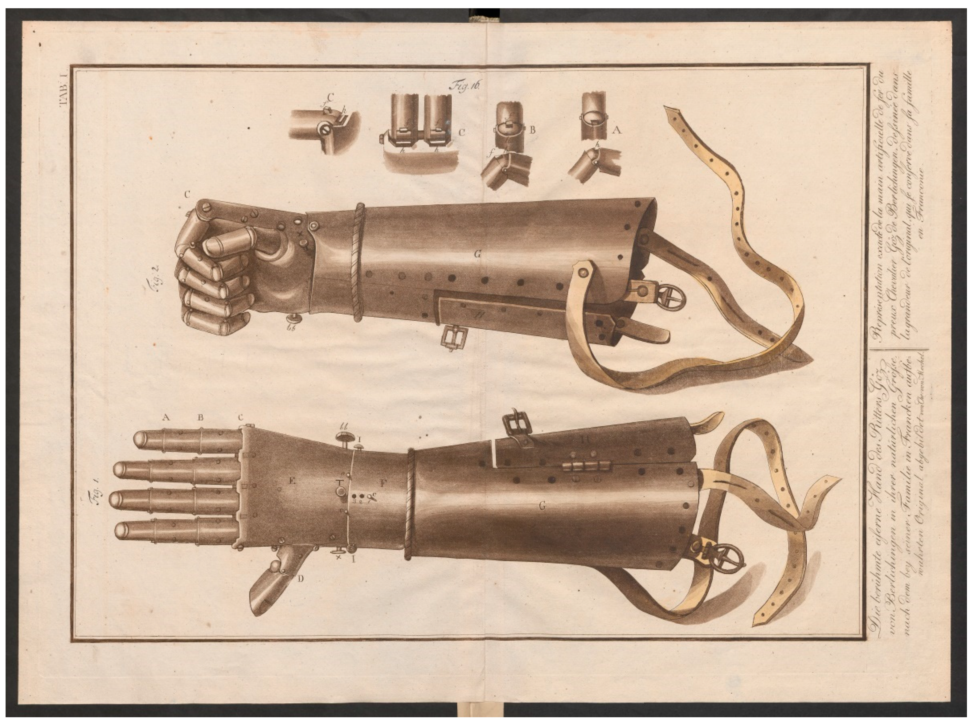
Picture credit: Tabula I from Christian von Mechel’s book, 1815 [3], entitled: “Die berühmte eiserne Hand des Ritters Göz von Berlichingen in ihrer natürlichen Größe, nach dem bey seiner Familie in Francken aufbewahrten Original abgebildet von Chr. von Mechel”. [“The famous iron hand of the knight Götz von Berlichingen in its natural size, illustrated by Chr. von Mechel after the original kept with his family in Franconia”]. Picture credit: Mechel, Christian von: Die eiserne Hand des tapfern deutschen Ritters Götz von Berlichingen: wie selbige noch bei seiner Familie in Franken aufbewahrt wird, sowohl von Aussen als von Innen dargestellt: nebst der Erklärung ihres für jene Zeiten […]. Berlin: gedruckt bei Georg Decker…, 1815. ETH-Bibliothek Zürich, Rar 2224, https://doi.org/10.3931/e-rara-14841 (accessed on 8 March 2021) (Public Domain Mark 1.0).
Figure 2.
Götz von Berlichingen’s second “Iron Hand”—overview of the mechanism of the fingers.
Figure 2.
Götz von Berlichingen’s second “Iron Hand”—overview of the mechanism of the fingers.
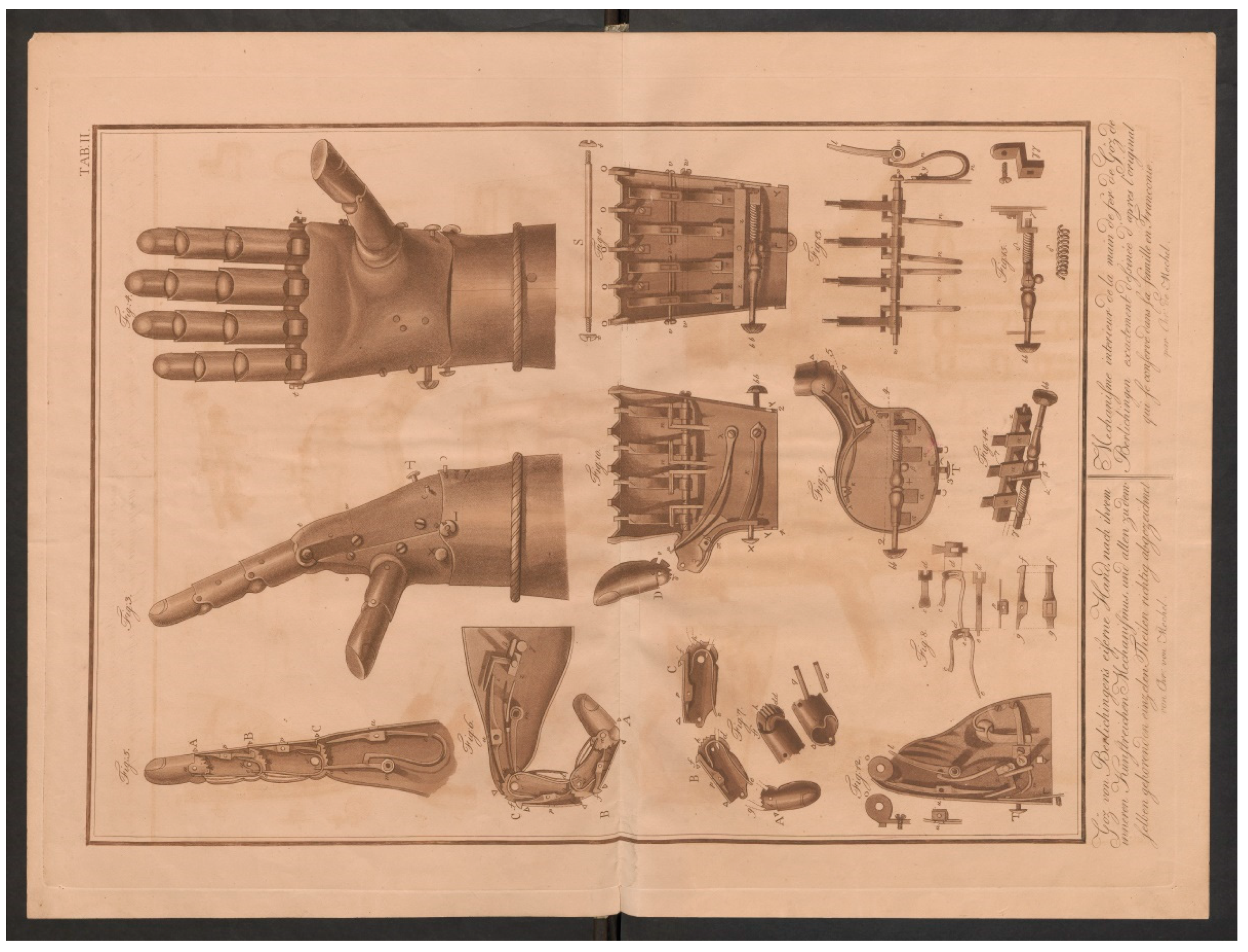
Picture credit: Tabula II from Christian von Mechel’s book, 1815 [3], entitled: “Göz von Berlichingen’s eiserne Hand, nach dem inneren kunstreichen Mechanismus, und allen zu demselben gehörenden Theilen richtig abgezeichnet von Chr. von Mechel”. [“Götz von Berlichingen’s iron hand, after the inner elaborate mechanism, and all parts belonging to the same correctly drawn by Chr. von Mechel”]. Picture credit: Mechel, Christian von: Die eiserne Hand des tapfern deutschen Ritters Götz von Berlichingen: wie selbige noch bei seiner Familie in Franken aufbewahrt wird, sowohl von Aussen als von Innen dargestellt: nebst der Erklärung ihres für jene Zeiten […]. Berlin: gedruckt bei Georg Decker…, 1815. ETH-Bibliothek Zürich, Rar 2224, https://doi.org/10.3931/e-rara-14841 (accessed on 8 March 2021) (Public Domain Mark 1.0).
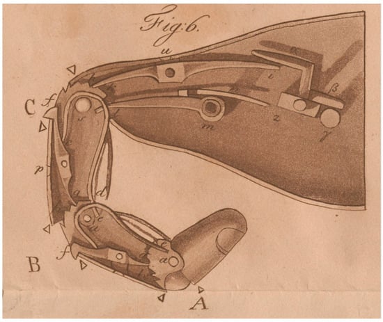
Figure 3.
Götz von Berlichingen’s second “Iron Hand”—detail of the finger mechanism: A–C: phalanges. A is hollow and closed on all sides. B and C are hollow but open on one side to accommodate articular vertebrae. a: Pins. The pins unite the phalanges. In addition, the two springs e are placed around them and the pin S. At d, the springs e are provided with an opening Δ into which the lower part of the spring of the abutting link engages. f, g: Locking lever. p: Hinge head. h: Teeth. i, k: Locking lever in hand body. In i, the locking lever is still connected to other levers. u: hinge head. l, m: tension hook. n: Spring. α, β: lever. γ: pusher. z: shaft.
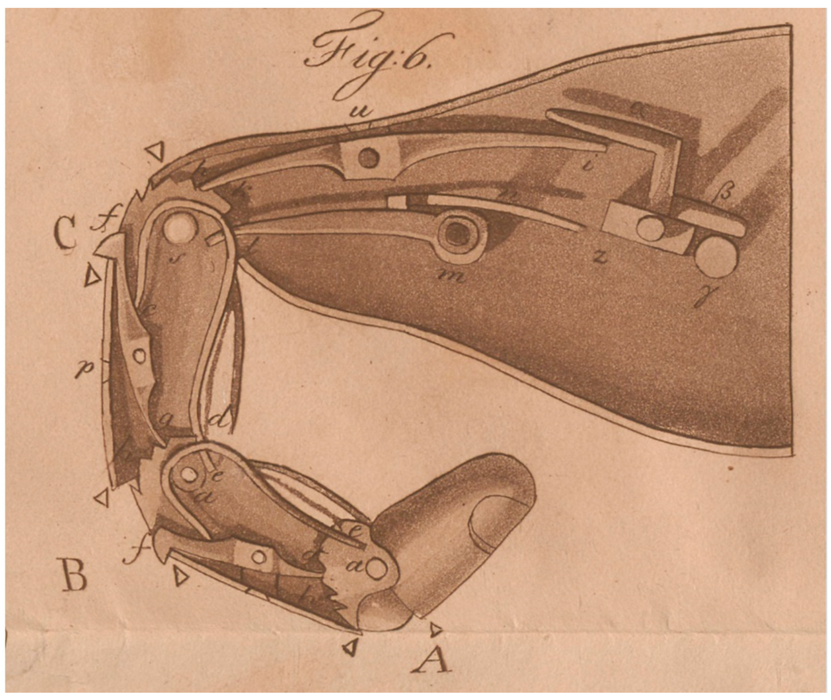
Picture credit: Illustration 6 (entitled “Figure 6”) enlarged from Tabula II (see Figure 2) of Christian von Mechel’s book, 1815 [3], entitled: “Die berühmte eiserne Hand des Ritters Göz von Berlichingen in ihrer natürlichen Größe, nach dem bey seiner Familie in Francken aufbewahrten Original abgebildet von Chr. von Mechel”. [“The famous iron hand of the knight Götz von Berlichingen in its natural size, illustrated by Chr. von Mechel after the original kept with his family in Franconia.”]. Picture credit: Mechel, Christian von: Die eiserne Hand des tapfern deutschen Ritters Götz von Berlichingen: wie selbige noch bei seiner Familie in Franken aufbewahrt wird, sowohl von Aussen als von Innen dargestellt: nebst der Erklärung ihres für jene Zeiten […]. Berlin: gedruckt bei Georg Decker…, 1815. ETH-Bibliothek Zürich, Rar 2224, https://doi.org/10.3931/e-rara-14841 (accessed on 8 March 2021) (Public Domain Mark 1.0).
Funding
This research received no external funding.
Institutional Review Board Statement
Not applicable.
Informed Consent Statement
Not applicable.
Conflicts of Interest
The author declares no conflict of interest.
References
- Otte, A. 3D Computer-Aided Design Reconstructions and 3D Multi-Material Polymer Replica Printings of the First “Iron Hand” of Franconian Knight Gottfried (Götz) von Berlichingen (1480–1562): An Overview. Prosthesis 2020, 2, 304–312. [Google Scholar] [CrossRef]
- Quasigroch, G. Die Handprothesen des fränkischen Reichsritters Götz von Berlichingen—Der Landshuter Unfall [The hand prostheses of the Franconian imperial knight Götz von Berlichingen–The Landshut accident]. Zeitschrift der Gesellschaft für Historische Waffen-und Kostümkunde 1980, 24, 108–112. [Google Scholar]
- Otte, A. Letter to the Editor: ArtiFacts: Gottfried “Götz” von Berlichingen-The “Iron Hand” of the Renaissance. Clin. Orthop. Relat. Res. 2021, 479, 210–211. [Google Scholar] [CrossRef] [PubMed]
- von Mechel, C. Die Eiserne Hand des Tapfern Deutschen Ritters Götz von Berlichingen [The Iron Hand of the Brave German Knight Götz von Berlichingen]; Georg Decker: Berlin, Germany, 1815. [Google Scholar] [CrossRef]
- Quasigroch, G. Die Handprothesen des fränkischen Reichsritters Götz von Berlichingen. 2. Fortsetzung: Die Zweithand [The hand prostheses of the Franconian imperial knight Götz von Berlichingen. 2nd continuation: The second hand]. Zeitschrift der Gesellschaft für Historische Waffen-und Kostümkunde 1983, 25, 103–120. [Google Scholar]
Publisher’s Note: MDPI stays neutral with regard to jurisdictional claims in published maps and institutional affiliations. |
© 2021 by the author. Licensee MDPI, Basel, Switzerland. This article is an open access article distributed under the terms and conditions of the Creative Commons Attribution (CC BY) license (http://creativecommons.org/licenses/by/4.0/).
