Article

Conductive Coatings on PDMS, PMMA, and Glass: Comparative Study of Graphene, Graphene Oxide, and Silver Nanoparticle Composites

1
Department of Applied Science, School of Science and Technology, Hong Kong Metropolitan University, Homantin, Kowloon, Hong Kong SAR, China
2
State Key Laboratory of Marine Pollution, City University of Hong Kong, Tat Chee Avenue, Kowloon, Hong Kong SAR, China
3
Shenzhen Research Institute of City University of Hong Kong, Shenzhen 518057, China
4
School of Environmental Science and Engineering, Tianjin University, Tianjin 300350, China
5
Department of Chemistry, City University of Hong Kong, Tat Chee Avenue, Kowloon, Hong Kong SAR, China
*
Author to whom correspondence should be addressed.
Electrochem 2024, 5(3), 380-392; https://doi.org/10.3390/electrochem5030025
Submission received: 16 July 2024 / Revised: 29 August 2024 / Accepted: 10 September 2024 / Published: 20 September 2024

Abstract

:
The development of conductive coatings has significant implications for microelectronics and electrochemistry. However, conductive coatings may exhibit different electrochemical properties when prepared on different substrate materials. This research explores the comparative performance of graphene, graphene oxide (GO), and silver nanoparticle (Ag NP) composites as conductive coatings on diverse substrate materials, including polydimethylsiloxane (PDMS), polymethyl methacrylate (PMMA), and glass. The study employed various preparation methods, such as mixing conductive materials with substrate materials and preparing copolymer composite materials. The conductive coating approach was found to be the most straightforward and convenient, with broader development prospects and fewer restrictive conditions. The results indicate that the distinct surface characteristics of the substrate materials influence the conductive properties of coating materials. Consequently, results show that graphene exhibits the highest conductivity on all three substrates, while GO is more conductive than Ag NPs on PMMA and PDMS but less conductive than Ag NPs on glass. That offers valuable insights into the selection of substrate materials and coating materials for the preparation of conductive materials.

Graphical Abstract

1. Introduction

The development of conductive composite materials by combining non-conductive polymers, glass, and other substrates with conductive nano-scale additives has garnered significant interest in the fields of microelectronics and electrochemistry [1]. This approach offers the potential to enhance the electrical properties of conventional materials, enabling their use in a wide range of applications, such as flexible electronics, energy storage devices, and sensors.
Various fabrication methods have been explored, including the deposition of conductive coatings on substrate materials [2], the blending of conductive fillers with substrate materials to create composite materials [3], and the synthesis of copolymer composite materials through the integration of conductive additives and polymerized monomers [4]. Among these approaches, the conductive coating method is the most straightforward and convenient, as it allows for the selective deposition of conductive materials on the surface of the substrate, offering broader prospects for development and fewer restrictive conditions.
Carbon-based conductive nanomaterials, such as carbon nanotubes, nanofibers, graphene, graphene oxide (GO), and reduced graphene oxide (rGO), have been identified as promising candidates for the fabrication of high-performance electrodes [5]. Graphene and its derivatives, such as GO and rGO, exhibit desirable material properties, including a large specific surface area, excellent electrical and thermal conductivity, high mechanical strength, and exceptional tensile characteristics [6,7,8,9,10]. These advantageous properties make graphene-based materials highly effective as conductive coatings, contributing to their widespread attention in the field. Building upon the beneficial properties of graphene-based materials, recent studies have explored novel methods for enhancing the conductive properties of composite materials. Kang et al. developed a novel approach for modifying polydimethylsiloxane (PDMS) with electronegative characteristics by incorporating GO and sodium dodecyl sulfate (SDS) surfactants [11]. The resulting porous PDMS@GO@SDS composite triboelectric nanogenerator demonstrated impressive voltage and current output, reaching 438 V and 11 μA/cm−2, respectively. This exceptional performance can be attributed to the synergistic effects of the anionic head group of SDS, the oxygen functional groups of GO, and the resulting enhanced negative charge on the PDMS substrate.
In a related study, Seo et al. reported the development of a sensitive electrochemical sensor for enzyme detection using a three-dimensional (3D) graphene structure [12]. The researchers utilized PDMS as the substrate and modified its surface with 3-aminopropyltriethoxysilane. Subsequently, the negatively charged graphene oxide flakes were electrostatically adsorbed onto the PDMS microcolumn surface. The amperometric response was employed to monitor the catalytic reaction process of the enzyme, and the sensor exhibited a low detection limit of 50 nM for phenol. These findings suggest that the 3D graphene micropillar structure not only increases the immobilization surface area of the enzyme but also enhances the biosensing capability through the high conductivity of graphene.
In addition to carbon-based materials, noble metal nanoparticles, such as silver nanoparticles (Ag NPs), have also been widely explored for their applications in conductive composite materials. Noble metal nanoparticles exhibit desirable characteristics, including good electrical conductivity, a high surface-to-volume ratio, a wide range of optical properties, and ease of synthesis with the ability for surface functionalization and modification [13]. Consequently, these nanomaterials have played a pivotal role in various fields, including biomedicine, biophysics research, and biosensors. Among the diverse noble metal nanoparticles, silver nanoparticles (Ag NPs) have garnered extensive attention due to their unique properties, such as non-toxicity, biocompatibility, and thermal conductivity [14,15,16,17]. Building upon the advantages of Ag NPs, Therriault et al. developed Ag NP-filled nanocomposites and utilized them as conductive coatings for aerospace composite structures [18]. This innovative approach demonstrates the potential of these nanomaterials in enhancing the conductivity of advanced materials, paving the way for their widespread application in various industries.
Most of the existing literature has focused on the development and optimization of individual conductive coating systems, without extensively comparing the electrochemical characteristics of the same conductive materials deposited on different substrate materials and, specifically, the influence of the substrate material type on the performance of the conductive coatings has not been thoroughly examined. Understanding the interplay between the substrate properties and the conductive coating performance is crucial for the rational design and selection of appropriate substrate–coating combinations to achieve desired electrochemical properties. By addressing this research gap, the present study investigated the preparation of composite conductive materials through the combination of various conductive coatings applied to diverse substrate materials. The distinct surface characteristics of the substrate materials may potentially influence the conductive properties of the coating materials. Consequently, a comparative analysis of the conductive properties of the composite materials was conducted, with the types of substrate materials and coating materials serving as the variables. The findings from this comprehensive investigation are expected to provide valuable insights into the selection of appropriate substrate materials and conductive coating materials for the fabrication of high-performance composite conductive materials with desirable electrochemical properties. It is undeniable that conductive coated composites have the potential to supplant traditional conductive materials and pave the way for a revolutionary manufacturing process for low-cost, thinner, lightweight, and more flexible electronic devices [10].

2. Materials and Methods

2.1. Chemicals and Apparatus

This study used (3-aminopropyl)triethoxysilane (APTES), colloidal silver nanoparticle solutions, and glass slides from Sigma Aldrich (St. Louis, MO, USA), as well as graphene and GO purchased from Suzhou Tanfeng Technology Co., Ltd. (Suzhou, China). The reagents used are all analytical grade and no further purification is required. The PDMS kit (SylgardTM 184) and polymethyl methacrylate (PMMA) were procured from Dow Co., Ltd. (Midland, MI, USA). The crystal structure of the materials was analyzed using an X-ray diffractometer (Rigaku, Tokyo, Japan), while the microstructure and morphology were studied using a Hitachi S-4800 scanning electron microscope (SEM). The spectral characteristics were analyzed using Raman spectroscopy using a Renishaw Invia Raman spectrometer, using a 532 nm laser source focused through a 20× microscope objective. Deionized water (18 MΩ/cm) was obtained from a Milli-Q water purification system.

2.2. Preparation of Composite Materials

PMMA/PDMS/Glass Sheet Preparation: The PMMA, PDMS, and glass substrates were first cut into uniform 1 cm × 1 cm pieces using a precision cutting tool. This ensured that all the samples had the same dimensions, which is crucial for maintaining consistency throughout the experimental procedures. The substrates were then thoroughly cleaned to remove any surface impurities that could interfere with the subsequent surface modifications. The cleaning process involved rinsing the substrates with deionized water and ethanol. Deionized water was used to remove any water-soluble contaminants, while ethanol effectively dissolved and removed any organic impurities on the surface. After the initial cleaning, the substrates were placed in a plasma cleaning system and subjected to a 1 min plasma treatment. The plasma cleaning process further enhanced the surface cleanliness by utilizing the reactive species generated in the plasma to remove any remaining contaminants and activate the surface. Following the plasma cleaning, the substrates were transferred to a preheated oven and dried at 60 °C for 30 min. This drying step was crucial to remove any residual moisture from the surface before proceeding with the next stage of the experiment.
Plasma Surface Modification: The dried substrates were then placed back into the plasma cleaning system, and plasma surface modification was performed for 3 min. This step aimed to introduce specific functional groups on the substrate surfaces, which would facilitate the subsequent APTES functionalization and the deposition of the conductive materials.
APTES Functionalization: A 5% aqueous solution of 3-aminopropyltriethoxysilane (APTES) was prepared. The plasma-modified substrates were then immersed in the APTES solution and stirred for 2 h at room temperature [16], allowing the silane molecules to react with the activated surface groups and form a self-assembled monolayer. After the APTES treatment, the substrates were removed from the solution and thoroughly washed with deionized water and ethanol to remove any residual APTES. Finally, the APTES-functionalized substrates were dried at 60 °C for an additional 30 min.
Conductive Material Coating: To prepare the conductive coatings, three separate aqueous dispersions were created: graphene (ethanol and Milli-Q water were mixed in a volume ratio of 1:1, 5 mg/mL), GO (5 mg/mL), and Ag NPs (0.02 mg/mL). A volume of 100 μL of each conductive material dispersion was then drop-coated onto the surface of the prepared substrates. The coated substrates were then dried at 60 °C for 2 h to evaporate the water and form the conductive coatings.
Coating Thickness Variation: After the initial conductive coating was completely dry, another 100 μL of the same conductive material dispersion was drop-coated onto the coated surface. The sample was then dried at 60 °C for 2 h to obtain a two-layer coating. This process was repeated to prepare coatings with one to five layers of thickness, allowing for the investigation of the effect of coating thickness on the electrochemical performance of the samples.

2.3. Electrochemical Test

Three-Electrode System Setup: The electrochemical measurements were conducted using a three-electrode system, which is a standard configuration for evaluating the electrochemical performance of materials. A platinum electrode clip was utilized as the working electrode, responsible for hosting the electrochemical reactions of interest. A platinum electrode was employed as the counter electrode, which completes the electrical circuit and allows the flow of current during the measurements. An Ag/AgCl electrode was selected as the reference electrode, providing a stable and well-defined potential against which the working electrode potential could be referenced. Careful consideration was given to the placement of the three electrodes, ensuring a consistent inter-electrode distance of 2 cm to maintain a stable and reproducible electrochemical environment.
Electrochemical Workstation Preparation: An electrochemical workstation, specifically the Zahner XC model, was used to perform the cyclic voltammetry (CV) and electrochemical impedance spectroscopy (EIS) measurements. This versatile instrument is capable of precisely controlling the applied potentials, monitoring the resulting currents, and recording the electrochemical data. To prepare the workstation for the experiments, the three-electrode system was connected to the appropriate ports on the workstation, and the relevant software was configured to manage the data acquisition and analysis.
Electrolyte Preparation: The electrochemical tests were conducted in an electrolyte solution composed of 0.1 M potassium chloride (KCl) and 2.5 mM potassium ferricyanide (K3Fe(CN)6) and potassium ferrocyanide (K4Fe(CN)6) [19]. This redox couple serves as a standard electrochemical probe, providing well-defined electrochemical responses that can be used to evaluate the performance of the conductive coatings. The electrolyte solution was freshly prepared and thoroughly mixed to ensure homogeneity
Cyclic Voltammetry (CV) Test: Using the three-electrode system immersed in the prepared electrolyte, CV measurements were performed. The working electrode potential was scanned over a predefined voltage range, and the resulting current response was recorded. The CV data provided insights into the redox reactions, charge transfer kinetics, and electrochemical reversibility of the conductive coatings.
Electrochemical Impedance Spectroscopy (EIS) Test: Complementing the CV measurements, electrochemical impedance spectroscopy (EIS) was conducted using the same three-electrode system and electrolyte. EIS involved applying a small-amplitude alternating current (AC) signal across a range of frequencies and measuring the system’s impedance response. The EIS data allowed for the evaluation of the charge transfer resistance, double-layer capacitance, and other electrochemical properties of the conductive coatings.
Data Processing: The acquired CV and EIS data were analyzed using the dedicated software provided by the electrochemical workstation. This software enabled the processing, visualization, and interpretation of the electrochemical measurements, allowing to extract relevant parameters and insights to understand the electrochemical performance of the conductive coatings.

3. Results and Discussion

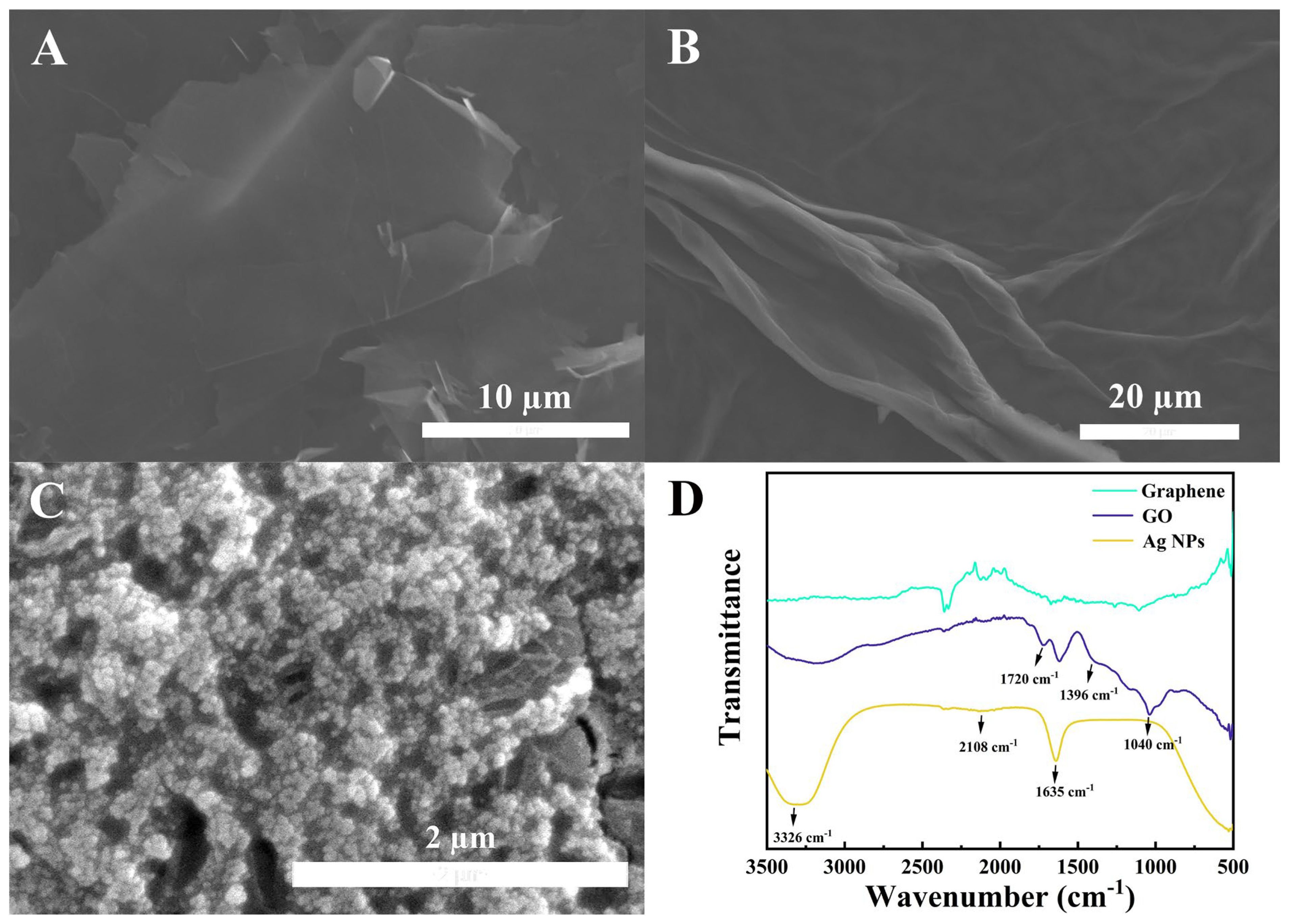
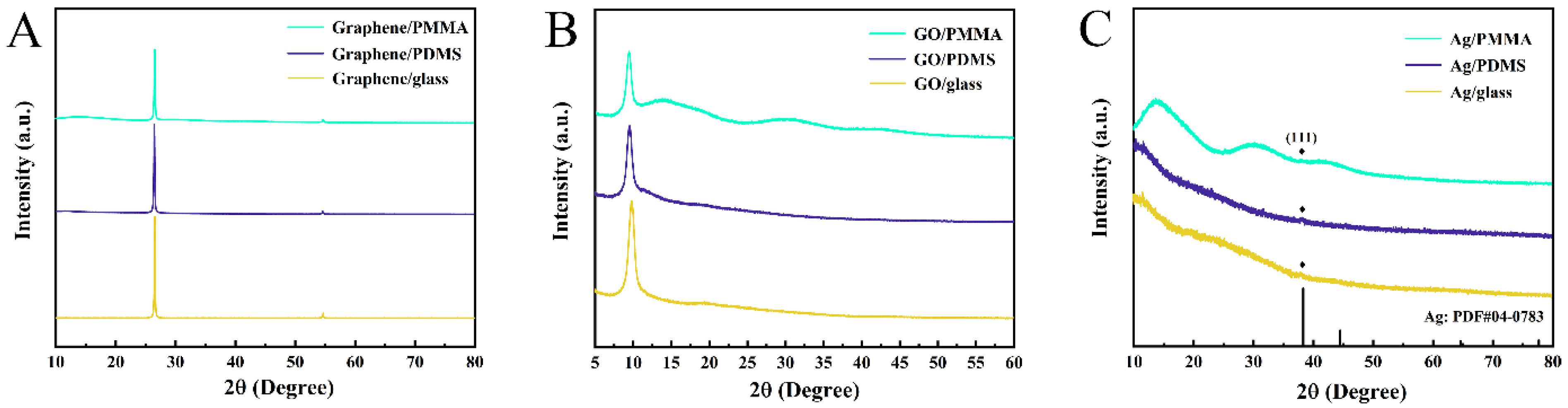
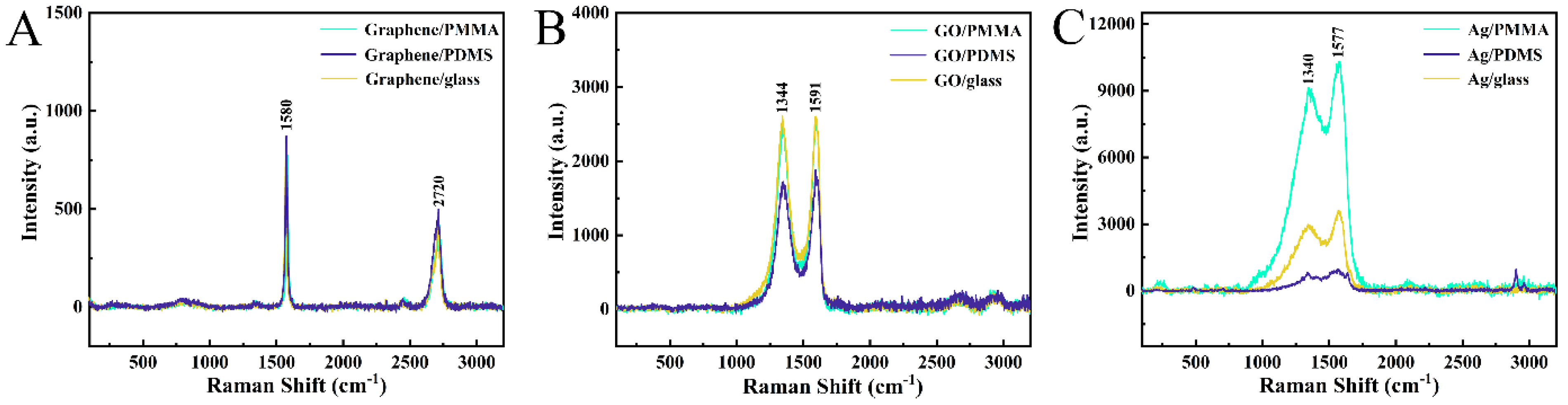
3.1. Physical Characterization of Coatings

The scanning electron microscope (SEM) images provide valuable insights into the morphological characteristics of the graphene, GO, and Ag NP coatings (prepared on PMMA). The graphene coating exhibits a distinct lamellar morphology, as shown in Figure 1A. The high-magnification SEM image reveals that the graphene sheets have a relatively large size, with a length and width of approximately 20 μm. This laminar structure is a result of the inherent two-dimensional nature of graphene, where the carbon atoms are arranged in a honeycomb-like lattice. The large lateral dimensions of the graphene sheets can contribute to enhanced electrical percolation pathways and improved charge transport within the coating.
In contrast, the GO coating displays a film-like structure with visible wrinkles, as depicted in Figure 1B. The high-magnification SEM image confirms that the film structure remains intact, without any apparent cracks near the folds. This observation suggests that the GO coating possesses superior mechanical strength and fracture resistance compared to the graphene coating. The wrinkled morphology of the GO coating can also create additional surface area, potentially leading to improved interactions with the substrate and enhanced adhesion.
In Figure 1C, the morphology of the silver nanoparticle coating is depicted. It is evident from the figure that the silver nanoparticles exhibit significant agglomeration when the coating is prepared using the drop-coating method. This agglomeration negatively impacts the uniformity and conductive properties of the coating [20].
The dispersion behavior of the materials in solution is a crucial factor for their application in coating preparation. Pristine graphene tends to exhibit poor dispersion due to the strong π–π stacking and van der Waals interactions, leading to agglomeration [21,22]. This can compromise the homogeneity and coverage of the graphene coating, potentially impacting its overall performance. In comparison, GO contains various oxygen-containing functional groups, such as carbonyl (C-O-C), hydroxyl (-OH), carbonyl (C=O), and carboxyl (-COOH) groups [23]. These functional groups enhance the dispersibility of GO by preventing agglomeration, making it a more suitable candidate for coating preparation compared to pristine graphene.
The superior mechanical properties and improved dispersibility of GO, as evidenced by the SEM analysis and the discussion of its functional groups, suggest that GO is a more favorable choice for the development of high-performance conductive coatings compared to pristine graphene. The wrinkled morphology and enhanced adhesion of the GO coating can contribute to improved interfacial interactions with the substrate, while the uniform dispersion of GO can lead to the formation of a more continuous and homogeneous conductive layer. By comparing the SEM images and photos of the graphene coating and the GO coating (Supporting Information, Figures S1 and S2), it can be clearly seen that due to the overlapping structure between the graphene layers, the coating has obvious fracture and shedding after being placed for a period of time, while the graphene oxide coating presents a good film morphology on the substrate material and does not fall off. Therefore, the graphene oxide coating has better mechanical properties and fracture resistance. The possible reason for this phenomenon is that the hydrophilicity of graphene is poor, and the dispersion is poor during the coating preparation process, resulting in agglomeration, which shows that the mechanical properties of the formed coating are poor.
Figure 1D shows the Fourier-transform infrared spectroscopy (FTIR) spectra of graphene, GO, and Ag NPs. Compared with the FTIR spectrum of graphene, in the FTIR spectrum of GO, there is a carboxyl C=O stretching vibration band at 1720 cm−1, an O–H deformation vibration band at 1396 cm−1, and a C=O stretching vibration band at 1040 cm−1 [24]. On the FTIR spectrum of Ag NPs, the band at 3326 cm−1 corresponds to O–H stretching vibration, and 1634 and 2108 cm−1 are consistent with C=C and C≡C, respectively. The peak at 1634 cm−1 is also assigned to the C=O stretching vibration of the amino acid tertiary amine. These are believed to be the chemical bonds and groups contained in the flavonoids and phenolics used to prepare Ag NPs [25].
The X-ray diffraction (XRD) analysis presented in Figure 2 provides valuable insights into the crystal structures of the prepared coatings on different substrate materials, confirming the successful incorporation of the desired conductive components.
Figure 2A presents the XRD patterns of the graphene coatings. The characteristic peaks observed at diffraction angles of 26.5° and 54.6° are consistent with the reported values for graphene [26]. These peaks correspond to the (002) and (004) crystal planes of graphene, respectively, indicating the successful deposition of the graphene material on the substrate surfaces.
In Figure 2B, the XRD patterns of the GO coatings are shown. A prominent peak can be observed at a diffraction angle of 10.8°, which is a characteristic signature of the GO material [27]. This peak corresponds to the (001) crystal plane of GO and confirms the successful incorporation of GO into the coatings on different substrate materials.
Additionally, a faint diffraction peak appears at a diffraction angle of 38.2° in the XRD patterns. This peak corresponds to the (111) crystal plane of Ag NPs, as confirmed by the standard PDF card (PDF#04-0783) [28]. Although the intensity of this peak is relatively low compared to the substrate materials, its presence confirms that the prepared coating contains the expected Ag NP component, even at a low concentration.
The XRD analysis provides convincing evidence that the prepared coatings successfully incorporate the desired materials, including graphene, GO, and Ag NPs, on various substrate surfaces. The characteristic diffraction peaks observed for each component validate the successful synthesis and deposition of the composite coatings, which is a crucial step in the development of high-performance conductive materials.
The Raman spectroscopy analysis presented in Figure 3 provides comprehensive insights into the structural and chemical characteristics of the different conductive coatings on various substrate materials.
Figure 3A showcases the Raman spectra of the graphene coatings. The characteristic Raman vibration peaks observed at 1580 cm−1 and 2720 cm−1 are consistent with the reported values for graphene [29]. Importantly, no Raman shift is observed in the samples with different substrate materials, indicating that the selected substrate material has a strong effect on the graphene coating, while matrix scattering has a negligible impact. This suggests that the graphene coating maintains its structural integrity and chemical properties regardless of the underlying substrate.
In Figure 3B, the Raman spectra of the GO coatings are presented. The D-band at 1344 cm−1 represents the sp2 lattice disorder due to structural defects in the GO material [30]. The G-band at 1591 cm−1 corresponds to the first-order scattering of E2g phonons by sp2 carbon and C–C stretching vibrations. Notably, the Raman peak intensity of the GO coating on PDMS is significantly lower compared to those on PMMA and glass. This suggests that the hydrogen bond strength between GO and PMMA or glass is higher than that of PDMS, resulting in a stronger interaction and closer combination of the coating with the PMMA and glass substrates [31].
Figure 3C presents the Raman spectra of the Ag NP coatings. The Raman vibration peaks observed at 1340 cm−1 and 1577 cm−1 are characteristic of Ag NPs [19]. Interestingly, the Raman peak intensities of the Ag NP coatings show a specific order: PMMA > glass > PDMS. This observation indicates that PMMA substrate has a potential Raman enhancement effect on Ag NPs [32], and we speculate that this is because plasma etching has a better surface modification effect on PMMA than on PDMS and glass. This observation indicates that the PMMA substrate has a potential Raman enhancement effect on the Ag NPs, likely due to the favorable interactions between the coating and the PMMA surface.
The Raman spectroscopy analysis highlights the structural differences between the graphene, GO, and Ag NP coatings, as well as their unique interactions with the various substrate materials. These insights are crucial for understanding the performance and optimization of the conductive coatings in practical applications. The findings suggest that the substrate material plays a significant role in influencing the structural and chemical characteristics of the conductive coatings. The stronger interactions between the coatings and the PMMA or glass substrates, as indicated by the Raman spectra, may contribute to improved adhesion, stability, and overall electrochemical performance of the composite materials.

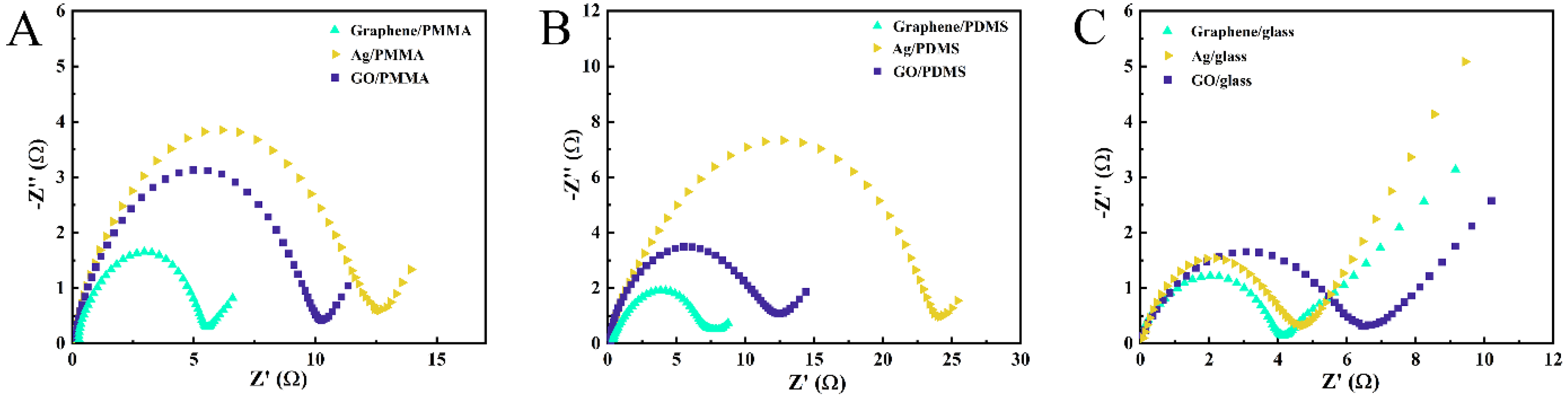
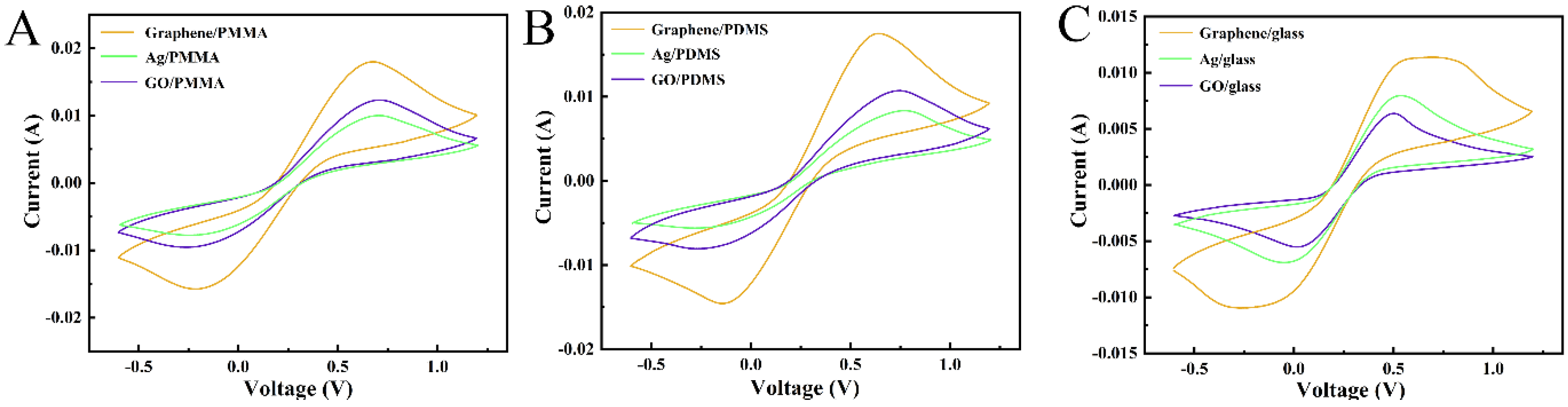
3.2. Electrochemical Characterization of Coatings

The electrochemical impedance spectroscopy (EIS) analysis presented in Figure 4 provides crucial insights into the conductive properties of the composite coatings on different substrate materials.
Figure 4A shows the EIS results for the composite coatings on the PMMA substrate. The impedance values follow the order: graphene/PMMA (5.5 Ω) < GO/PMMA (10.2 Ω) < Ag/PMMA (12.5 Ω). These results indicate that when PMMA is the substrate material, the graphene/PMMA composite demonstrates the lowest impedance and the highest conductivity.
Similarly, Figure 4B presents the EIS results for the composite coatings on the PDMS substrate. The impedance values follow the order: graphene/PDMS (7.5 Ω) < GO/PDMS (12.5 Ω) < Ag/PDMS (23.8 Ω). These findings suggest that when PDMS is used as the substrate material, the graphene/PDMS composite exhibits the lowest impedance and, consequently, the best conductivity among the tested materials.
In contrast, when glass is used as the substrate material, the impedance values exhibit a slightly different trend, as shown in Figure 4C. The impedance values follow the order: graphene/glass (4.2 Ω) < Ag/glass (4.6 Ω) < GO/glass (6.5 Ω). These results suggest that for the glass substrate, the graphene/glass composite has the lowest impedance and the highest conductivity among the tested materials.
The comprehensive EIS analysis reveals that the choice of substrate material significantly influences the conductive properties of the composite coatings. Specifically, the graphene-based composites exhibit the lowest impedance and the highest conductivity, regardless of the substrate material. These findings highlight the superior conductive performance of graphene-based materials, which can be effectively leveraged in various applications requiring high-performance conductive coatings.
The observed differences in the conductive properties across the substrate materials can be attributed to the specific interactions and interfacial characteristics between the conductive coatings and the substrate surfaces. The stronger adhesion and compatibility between the graphene coatings and the substrate materials, as suggested by the Raman spectroscopy analysis, may contribute to the enhanced conductive performance of the graphene-based composites.
The cyclic voltammetry (CV) analysis presented in Figure 5 provides additional confirmation of the conductive properties of the composite coatings on different substrate materials, complementing the insights obtained from the electrochemical impedance spectroscopy (EIS) results. In the CV technique, a larger anodic peak current value indicates better conductivity of the tested sample [33].
Figure 5A shows the CV spectra for the composite coatings on the PMMA substrate. The order of the anodic peak current values is consistent with the impedance values observed in Figure 4A, where the graphene/PMMA composite had the lowest impedance and the highest conductivity among the tested materials.
Similarly, in Figure 5B, which depicts the CV results for the composite coatings on the PMMA substrate, the order of the anodic peak current values is: graphene/PDMS > GO/PDMS > Ag/PDMS. This order aligns with the impedance values observed in Figure 4B, where the graphene/PMMA composite had the lowest impedance and the highest conductivity among the tested materials.
Meanwhile, Figure 5C presents the CV spectra for the composite coatings on the glass substrate. The order of the anodic peak current values is: graphene/glass > Ag/glass > GO/glass. This order is also consistent with the impedance results shown in Figure 4C, where the graphene/glass composite had the lowest impedance and the highest conductivity.
The CV test results corroborate the findings from the EIS analysis, further reinforcing the superior conductive performance of the graphene-based composite coatings, regardless of the substrate material. This comprehensive electrochemical characterization provides a robust evaluation of the conductive properties of the different composite materials, enabling informed decision making for their practical applications.
The alignment between the EIS and CV results underscores the reliability and consistency of the findings, strengthening the confidence in the comparative assessment of the conductive properties of the composite coatings. The superiority of the graphene-based composites in terms of low impedance and high conductivity, across various substrate materials, highlights the versatility and potential of graphene as a high-performance conductive coating material. Based on the above results and discussions, the comparison of the conductive properties of graphene, GO, and silver nanoparticle coatings on PMMA, PDMS, and glass is summarized in Table 1.

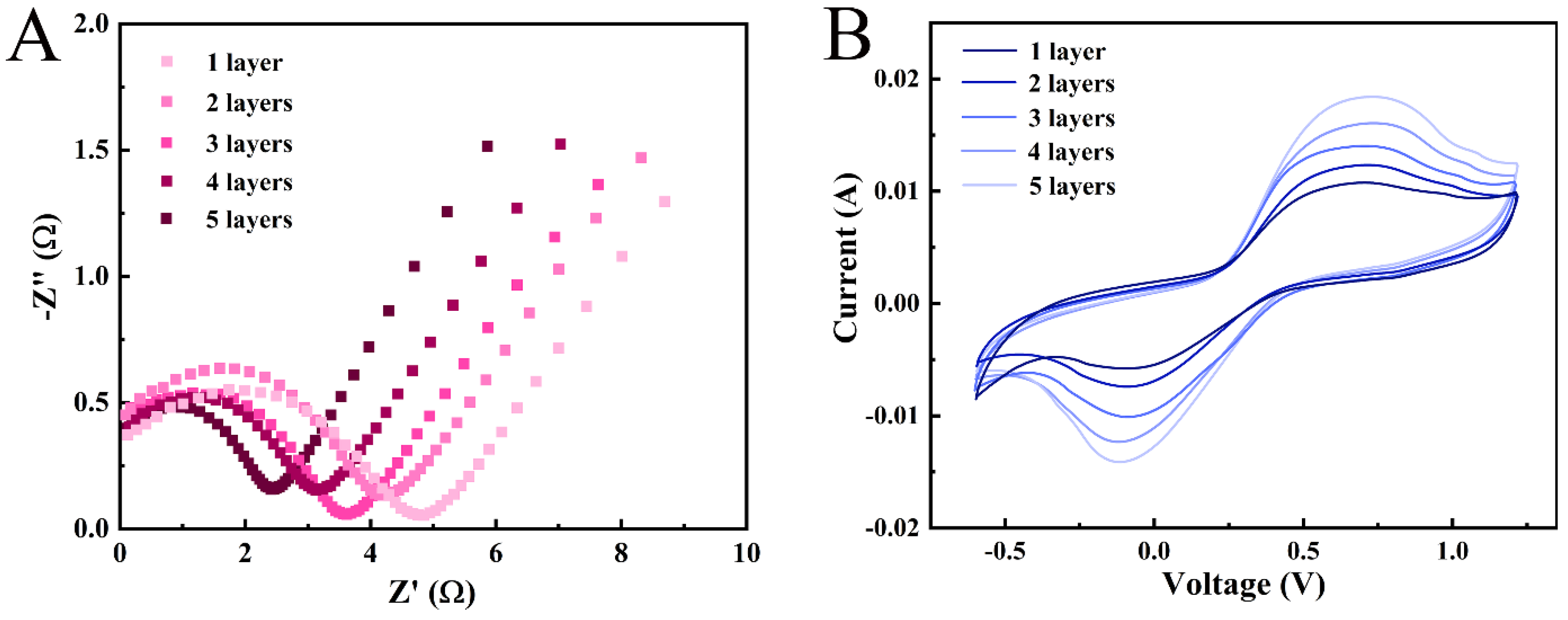
3.3. Multilayers of Graphene

In order to explore the effect of coating thickness on conductivity, graphene was drop-coated on PMMA for different times to represent graphene coatings at different thicknesses. The results presented in Figure 6 highlight the crucial importance of optimizing the coating thickness to achieve the desired conductive performance in the graphene/PMMA composite material.
The EIS analysis in Figure 6A demonstrates that as the number of graphene coating layers increases, the surface impedance of the composite gradually decreases. This inverse relationship between the coating thickness and the impedance indicates that thicker graphene coatings result in higher conductivity. The CV results presented in Figure 6B further corroborate this observation. The peak current value, which is positively correlated with the conductivity of the sample, increases with the increase in the number of graphene coating layers. This finding aligns with the EIS results and confirms that the conductivity of the graphene/PMMA composite is directly proportional to the thickness of the graphene coating.
The relationship between the coating thickness and the conductivity can be explained by the resistivity formula:
R = ρ × l s
where R is resistance, ρ is resistivity, l is material length, and s is material cross-sectional area.
In the case of the conductive coating, the cross-sectional area of the coating is positively correlated with the thickness of the coating. Therefore, as the coating thickness increases, the cross-sectional area also increases, resulting in a lower resistance and, consequently, higher conductivity.
These results demonstrate the importance of optimizing the coating thickness to achieve the desired conductive performance. This knowledge can be crucial in the practical application of conductive coatings, as highlighted by the example of the fabric-based triboelectric nanogenerator (TENG) developed by Huang et al. [34]. The authors suggest that replacing the GO with graphene in the TENG could lead to even better performance, further emphasizing the significance of selecting the appropriate conductive coating material based on the substrate material and the specific application requirements.
By understanding the relationship between the coating thickness and the conductive properties, researchers and engineers can tailor the graphene coating thickness to meet the performance objectives of their target applications. This optimization process can involve balancing factors such as cost, ease of fabrication, and the desired level of conductivity to develop high-performance conductive coatings that are well-suited for a wide range of practical uses.

4. Conclusions

Based on the comprehensive electrochemical characterization and analysis presented in this study, the following key conclusions can be drawn:
  • Conductive coating performance is highly dependent on the choice of substrate material. The results from the EIS and CV tests show that the graphene-based composite coatings exhibit superior conductivity compared to the silver and graphene oxide coatings, regardless of the substrate material (PDMS, PMMA, or glass).
  • For the graphene/PMMA composite, the conductivity is directly proportional to the thickness of the graphene coating. As the number of graphene coating layers increases, the surface impedance decreases, and the anodic peak current value in the CV test increases, indicating higher conductivity.
  • The relationship between the coating thickness and conductivity can be explained by the resistivity formula, where the cross-sectional area of the coating is positively correlated with the coating thickness. Thicker coatings result in a larger cross-sectional area, leading to lower resistance and higher conductivity.
  • The superior conductive performance of graphene-based coatings highlights their potential for various applications, such as the fabric-based triboelectric nanogenerator (TENG) discussed in the text. Replacing the graphene oxide with graphene in the TENG could lead to even better performance, emphasizing the importance of selecting the appropriate conductive coating material based on the substrate and the application requirements.
Overall, these findings provide valuable insights into the factors that influence the conductivity of conductive coatings, which can guide the development and optimization of innovative materials and devices with enhanced performance.

Supplementary Materials

The following supporting information can be downloaded at: https://www.mdpi.com/article/10.3390/electrochem5030025/s1, Figure S1: Comparison of SEM images and photos of graphene and GO.; Figure S2: Photographs of graphene, GO and Ag NPs coatings on PMMA, PDMS and glass.

Author Contributions

Investigation, methodology, writing original draft preparation, J.S.; preparation of composite materials, Q.G.; characterization of materials, data curation, formal analysis, W.D.; software, resource, writing-reviewing and editing, J.L.C.; writing-reviewing, project administration, G.M.; writing-reviewing, project administration, Y.-K.P. All authors have read and agreed to the published version of the manuscript.

Funding

The work described in this paper was supported by a grant from the Research Grants Council of the Hong Kong Special Administrative Region, China (UGC/FDS16/M(P)05/21) and partially by a grant from the Shenzhen Fundamental Research Program (JCYJ20190808181607387), a grant from the State Key Laboratory of Marine Pollution (SKLMP) Seed Collaborative Research Fund (SKLMP/SCRF/0066), and a grant from Hong Kong Metropolitan University Research Grant (RD/2023/2.20).

Institutional Review Board Statement

Not applicable.

Informed Consent Statement

Not applicable.

Data Availability Statement

The raw data supporting the conclusions of this article will be made available by the authors on request.

Conflicts of Interest

The authors declare no conflict of interest.

References

  1. Kwon, J.; Evans, K.; Le, M.; Arnold, D.; Yildizdag, M.E.; Zohdi, T.; Ritchie, R.O.; Xu, T. Scalable Electrically Conductive Spray Coating Based on Block Copolymer Nanocomposites. ACS Appl. Mater. Interfaces 2020, 12, 8687–8694. [Google Scholar] [CrossRef] [PubMed]
  2. Wang, Y.; Huang, K.; Derré, A.; Puech, P.; Rouzière, S.; Launois, P.; Castro, C.; Monthioux, M.; Pénicaud, A. Conductive graphene coatings synthesized from graphenide solutions. Carbon 2017, 121, 217–225. [Google Scholar] [CrossRef]
  3. Cuttaz, E.; Goding, J.; Vallejo-Giraldo, C.; Aregueta-Robles, U.; Lovell, N.; Ghezzi, D.; Green, R.A. Conductive elastomer composites for fully polymeric, flexible bioelectronics. Biomater. Sci. 2019, 7, 1372–1385. [Google Scholar] [CrossRef] [PubMed]
  4. Cakmak, G.; Küçükyavuz, Z.; Küçükyavuz, S. Conductive copolymers of polyaniline, polypyrrole and poly(dimethylsiloxane). Synth. Met. 2005, 151, 10–18. [Google Scholar] [CrossRef]
  5. Eivazzadeh-Keihan, R.; Bahojb Noruzi, E.; Chidar, E.; Jafari, M.; Davoodi, F.; Kashtiaray, A.; Ghafori Gorab, M.; Masoud Hashemi, S.; Javanshir, S.; Ahangari Cohan, R.; et al. Applications of carbon-based conductive nanomaterials in biosensors. Chem. Eng. J. 2022, 442, 136183. [Google Scholar] [CrossRef]
  6. Roh, E.; Hwang, B.-U.; Kim, D.; Kim, B.-Y.; Lee, N.-E. Stretchable, Transparent, Ultrasensitive, and Patchable Strain Sensor for Human–Machine Interfaces Comprising a Nanohybrid of Carbon Nanotubes and Conductive Elastomers. ACS Nano 2015, 9, 6252–6261. [Google Scholar] [CrossRef]
  7. Seol, Y.G.; Trung, T.Q.; Yoon, O.-J.; Sohn, I.-Y.; Lee, N.-E. Nanocomposites of reduced graphene oxide nanosheets and conducting polymer for stretchable transparent conducting electrodes. J. Mater. Chem. 2012, 22, 23759–23766. [Google Scholar] [CrossRef]
  8. Amjadi, M.; Kyung, K.-U.; Park, I.; Sitti, M. Stretchable, Skin-Mountable, and Wearable Strain Sensors and Their Potential Applications: A Review. Adv. Funct. Mater. 2016, 26, 1678–1698. [Google Scholar] [CrossRef]
  9. Potts, J.R.; Dreyer, D.R.; Bielawski, C.W.; Ruoff, R.S. Graphene-based polymer nanocomposites. Polymer 2011, 52, 5–25. [Google Scholar] [CrossRef]
  10. Tran, T.S.; Dutta, N.K.; Choudhury, N.R. Graphene inks for printed flexible electronics: Graphene dispersions, ink formulations, printing techniques and applications. Adv. Colloid Interface Sci. 2018, 261, 41–61. [Google Scholar] [CrossRef]
  11. Harnchana, V.; Ngoc, H.V.; He, W.; Rasheed, A.; Park, H.; Amornkitbamrung, V.; Kang, D.J. Enhanced Power Output of a Triboelectric Nanogenerator using Poly(dimethylsiloxane) Modified with Graphene Oxide and Sodium Dodecyl Sulfate. ACS Appl. Mater. Interfaces 2018, 10, 25263–25272. [Google Scholar] [CrossRef] [PubMed]
  12. Liu, F.; Piao, Y.; Choi, J.S.; Seo, T.S. Three-dimensional graphene micropillar based electrochemical sensor for phenol detection. Biosens. Bioelectron. 2013, 50, 387–392. [Google Scholar] [CrossRef]
  13. Borah, B.; Dash, R.K. Improved dielectric properties of rGO/PDMS composites by incorporation of Ag nanoparticles. J. Mater. Sci. Mater. Electron. 2022, 33, 12334–12350. [Google Scholar] [CrossRef]
  14. Chernousova, S.; Epple, M. Silver as Antibacterial Agent: Ion, Nanoparticle, and Metal. Angew. Chem. Int. Ed. 2013, 52, 1636–1653. [Google Scholar] [CrossRef] [PubMed]
  15. Zhang, W.; Bi, E.; Li, M.; Gao, L. Synthesis of Ag/RGO composite as effective conductive ink filler for flexible inkjet printing electronics. Colloids Surf. A Physicochem. Eng. Asp. 2016, 490, 232–240. [Google Scholar] [CrossRef]
  16. Yang, W.; Wang, C.; Arrighi, V.; Vilela, F. One step synthesis of a hybrid Ag/rGO conductive ink using a complexation–covalent bonding based approach. J. Mater. Sci. Mater. Electron. 2017, 28, 8218–8230. [Google Scholar] [CrossRef]
  17. Darabdhara, G.; Das, M.R.; Singh, S.P.; Rengan, A.K.; Szunerits, S.; Boukherroub, R. Ag and Au nanoparticles/reduced graphene oxide composite materials: Synthesis and application in diagnostics and therapeutics. Adv. Colloid Interface Sci. 2019, 271, 101991. [Google Scholar] [CrossRef]
  18. Dermanaki Farahani, R.; Gagne, M.; Klemberg-Sapieha, J.E.; Therriault, D. Electrically Conductive Silver Nanoparticles-Filled Nanocomposite Materials as Surface Coatings of Composite Structures. Adv. Eng. Mater. 2016, 18, 1189–1199. [Google Scholar] [CrossRef]
  19. Butovsky, E.; Perelshtein, I.; Gedanken, A. Air stable core–shell multilayer metallic nanoparticles synthesized by RAPET: Fabrication, characterization and suggested applications. J. Mater. Chem. 2012, 22, 15025–15030. [Google Scholar] [CrossRef]
  20. Szuwarzyński, M.; Mazur, Ł.; Borkowski, M.; Maćkosz, K.; Giżyński, K.; Mazur, T. Enhanced Assembly of Ag Nanoparticles for Surface-Independent Fabrication of Conductive Patterns. ACS Appl. Nano Mater. 2022, 5, 12711–12719. [Google Scholar] [CrossRef]
  21. Smith, A.T.; LaChance, A.M.; Zeng, S.; Liu, B.; Sun, L. Synthesis, properties, and applications of graphene oxide/reduced graphene oxide and their nanocomposites. Nano Mater. Sci. 2019, 1, 31–47. [Google Scholar] [CrossRef]
  22. Guo, Y.; Yang, X.; Ruan, K.; Kong, J.; Dong, M.; Zhang, J.; Gu, J.; Guo, Z. Reduced Graphene Oxide Heterostructured Silver Nanoparticles Significantly Enhanced Thermal Conductivities in Hot-Pressed Electrospun Polyimide Nanocomposites. ACS Appl. Mater. Interfaces 2019, 11, 25465–25473. [Google Scholar] [CrossRef] [PubMed]
  23. Wang, Z.; Nelson, J.K.; Hillborg, H.; Zhao, S.; Schadler, L.S. Graphene Oxide Filled Nanocomposite with Novel Electrical and Dielectric Properties. Adv. Mater. 2012, 24, 3134–3137. [Google Scholar] [CrossRef] [PubMed]
  24. Çiplak, Z.; Yildiz, N.; Çalimli, A. Investigation of Graphene/Ag Nanocomposites Synthesis Parameters for Two Different Synthesis Methods. Fuller. Nanotub. Carbon Nanostruct. 2015, 23, 361–370. [Google Scholar] [CrossRef]
  25. Mehata, M.S. Green route synthesis of silver nanoparticles using plants/ginger extracts with enhanced surface plasmon resonance and degradation of textile dye. Mater. Sci. Eng. B 2021, 273, 115418. [Google Scholar] [CrossRef]
  26. Farbod, M.; Shojaeenezhad, S.S. A three-dimensional Ag nanoparticle/graphene hydrogel composite and its application as an improved supercapacitor’s electrode. J. Solid State Electrochem. 2019, 23, 3009–3017. [Google Scholar] [CrossRef]
  27. Yasin, G.; Arif, M.; Shakeel, M.; Dun, Y.; Zuo, Y.; Khan, W.Q.; Tang, Y.; Khan, A.; Nadeem, M. Exploring the Nickel–Graphene Nanocomposite Coatings for Superior Corrosion Resistance: Manipulating the Effect of Deposition Current Density on its Morphology, Mechanical Properties, and Erosion-Corrosion Performance. Adv. Eng. Mater. 2018, 20, 1701166. [Google Scholar] [CrossRef]
  28. Corsino, D.C.; Balela, M.D.L. Room temperature sintering of printer silver nanoparticle conductive ink. IOP Conf. Ser. Mater. Sci. Eng. 2017, 264, 012020. [Google Scholar] [CrossRef]
  29. Hafez, H.A.; Kovalev, S.; Deinert, J.-C.; Mics, Z.; Green, B.; Awari, N.; Chen, M.; Germanskiy, S.; Lehnert, U.; Teichert, J.; et al. Extremely efficient terahertz high-harmonic generation in graphene by hot Dirac fermions. Nature 2018, 561, 507–511. [Google Scholar] [CrossRef]
  30. Jiang, K.-C.; Xin, S.; Lee, J.-S.; Kim, J.; Xiao, X.-L.; Guo, Y.-G. Improved kinetics of LiNi1/3Mn1/3Co1/3O2 cathode material through reduced graphene oxide networks. Phys. Chem. Chem. Phys. 2012, 14, 2934–2939. [Google Scholar] [CrossRef]
  31. Hidayah, N.M.S.; Liu, W.-W.; Lai, C.-W.; Noriman, N.Z.; Khe, C.-S.; Hashim, U.; Lee, H.C. Comparison on graphite, graphene oxide and reduced graphene oxide: Synthesis and characterization. AIP Conf. Proc. 2017, 1892, 150002. [Google Scholar] [CrossRef]
  32. Bao, Y.; Lai, C.; Zhu, Z.; Fong, H.; Jiang, C. SERS-active silver nanoparticles on electrospun nanofibers facilitated via oxygen plasma etching. RSC Adv. 2013, 3, 8998–9004. [Google Scholar] [CrossRef]
  33. Xu, H.; Wang, X.; Chen, R.; Yu, Z. Voltammetric determination of epinephrine in the presence of uric acid based on aminated graphene and Ag NPs hybrid membrane modified electrode. Chem. Res. Chin. Univ. 2014, 30, 205–210. [Google Scholar] [CrossRef]
  34. Yang, C.-R.; Ko, C.-T.; Chang, S.-F.; Huang, M.-J. Study on fabric-based triboelectric nanogenerator using graphene oxide/porous PDMS as a compound friction layer. Nano Energy 2022, 92, 106791. [Google Scholar] [CrossRef]
Figure 1. The SEM images (AC) and FTIR spectra (D) of graphene, GO, and Ag NPs.
Electrochem 05 00025 g001
Figure 2. XRD patterns of graphene (A), GO (B), and Ag NP (C) coatings prepared on three different substrate materials.
Electrochem 05 00025 g002
Figure 3. Raman spectra of graphene (A), GO (B), and Ag NP (C) coatings prepared on 3 different substrate materials.
Electrochem 05 00025 g003
Figure 4. EIS of graphene, GO, and Ag NP coatings prepared on PMMA (A), PDMS, (B) and glass (C).
Electrochem 05 00025 g004
Figure 5. CV of graphene, GO, and Ag NP coatings prepared on PMMA (A), PDMS, (B) and glass (C).
Electrochem 05 00025 g005
Figure 6. EIS (A) and CV (B) of graphene/PMMA with different film thicknesses.
Electrochem 05 00025 g006
Table 1. Comparison of the conductive properties of graphene, GO, and silver nanoparticle coatings on PMMA, PDMS, and glass.
Sample on SubstrateConductive Performance Comparison
Graphene/PMMAGraphene/PMMA > GO/PMMA > Ag/PMMA
GO/PMMA
Ag NPs/PMMA
Graphene/PDMSGraphene/PDMS > GO/PDMS > Ag/PDMS
GO/PDMS
Ag NPs/PDMS
Graphene/glassGraphene/glass > Ag/glass > GO/glass
GO/glass
Ag NPs/glass
Disclaimer/Publisher’s Note: The statements, opinions and data contained in all publications are solely those of the individual author(s) and contributor(s) and not of MDPI and/or the editor(s). MDPI and/or the editor(s) disclaim responsibility for any injury to people or property resulting from any ideas, methods, instructions or products referred to in the content.

