Abstract
Due to climate concerns, most countries are looking for alternative ways to generate energy in a clean, efficient, and environmentally friendly way. Currently, a practical and technically feasible solution can be obtained by integrating a gas turbine and a solid oxide fuel cell to form a hybrid system. Experimental studies of the thermophysical, electrochemical, and other internal processes in solid oxide fuel cells are an expensive procedure, so theoretical tools such as simulations are very important in the analysis and design of solid oxide fuel cell stack systems. In this work, a 3D model of a planar fuel cell was studied. Numerical modeling was carried out, taking into account the flow channel design, the movement of thermal air, and fuel flows. A calculation of the thermodynamic parameters of a solid oxide fuel cell with hydrocarbon fuel has been carried out. In conclusion, some constructive perspectives and recommendations for future research are offered.
1. Introduction
Solid oxide fuel cells (SOFCs) are a promising energy and resource-efficient technology [1]. However, carrying out experimental studies of SOFCs under various operating conditions is not always possible due to technical and economic reasons. It is sometimes not possible to measure all flow characteristics such as the temperature, pressure, or distribution of flow rates through a fuel cell using experimental methods. SOFC numerical simulations reveal much more possibilities for researchers [2,3,4]. The accurate modeling of SOFCs is a complex task. The equations of mass, energy, charge, electron transport, and electrochemistry should be calculated simultaneously at the boundaries of liquid, solids, and porous media. This physico-electrochemical task with a large number of involved parameters can be solved by numerical simulations using commercial software packages [5,6].
The finite difference method (FDM), the finite volume method (FVM), and the finite element method (FEM) are the main applied numerical approaches for SOFC modeling [7]. There are many commercial CFD packages based on the FVM and the FEM that are used for simulations of fluid and gas flows. The ANSYS and COMSOL software systems are the most frequently presented in the scientific literature among all available programs for CFD, multiphysics, chemistry, and electrochemistry. There are fundamental differences between these software packages. For example, ANSYS is based on the FVM, while COMSOL is based on the FEM [8,9,10].
Tasks that can be solved by numerical methods include the modeling of electrochemical processes, collector design, performance modeling, studying the influence of the electrode microstructure, analyzing thermal stresses, and developing new structural elements.
Based on the literature data, eight areas related to the modeling and simulation of solid oxide fuel cells can be distinguished (Table 1) [11,12,13,14].

Table 1.
Current SOFC modeling areas.
An important advantage of SOFCs is the possibility of internal conversion of a hydrocarbon fuel into hydrogen. Therefore, it is possible to use methane and synthesis gas as fuel without a pre-reformer system. In the case of external fuel reforming, SOFCs can use complex hydrocarbons, biofuels, and industrial and social waste, but it is necessary to carry out purification from sulfur. For example, during oil refining, a hydrogen-containing gas is formed with hydrocarbons from C1 to C7, which can be converted by steam reforming to synthesis gas and then fed to the SOFC.
The issues of improving the environmental friendliness of industrial enterprises and reducing the negative impact of gas waste on the environment are relevant today. Therefore, the purpose of the paper is to study the possibility of SOFC operation on various fuels and to compare the parameters of operation on hydrogen and oil refining waste.
2. Materials and Methods
Numerical simulations were carried out on a personal computer with an Intel Xeon Gold processor, 512 GB of total RAM and a 1 TB SSD for more accurate and faster mathematical calculations.
The calculations were carried out in the COMSOL Multiphysics 2021 universal software system for finite element analyses.
The geometric 3D model was built according to the specification of the actual stack design. The model is based on a 1 kW anode-supported planar SOFC developed in China. The cell size of the SOFC is 16 × 16 cm2, with an active area of 10 × 10 cm2. Flows enter/exit the stack (fuel cells) through gas inlets/outlets (manifolds). Each fuel cell module block consists of a membrane–electrode complex cathode (positive electrode), an electrolyte, an anode (negative electrode), air and fuel channels, and interconnections. Thus, the electrochemical active area of the 30-element SOFC stack consists of 900 identical block modules. Due to the same geometry, a numerical simulation of one block of the SOFC cell was carried out. The dimensions and geometry of the block are presented in Table 2.
Table 2.
Geometry and materials of the SOFC cell block.
The input parameters and composition of the simulated gas flows are presented in Table 3. Hydrogen, methane, and synthesis gas were used as fuel. The composition of the synthesis gas, which was obtained from the gas waste of oil refining by steam reforming, was modeled in the Ansys Fluent 2021 software package at a temperature of 873 K and a pressure of 10 bar on a nickel catalyst.
Table 3.
Fuel cell inlet gas flow characteristics.
A mesh with hexahedral cells was chosen for numerical calculations. The number of cells was 2.2 million. The mesh quality indicator was close to 1.
The following assumptions and simplifications were used for calculations using the numerical model:
- Atmospheric inlet pressure;
- The flows are laminar;
- For carbonaceous fuels, only steam reforming and carbon dioxide reforming are permitted;
- The operating temperature range is 700–1000 °C;
- The seal between structural elements is assumed to be ideal;
- No leakage effect;
- Heat loss to the environment is based on radiation only;
- Joule heating is neglected;
- The installation works in a stationary mode;
- Chemical reactions occur in one stage.
The real processes in a fuel cell are a combination of matter transfer, heat transfer, electron transfer, and electrochemistry.
The velocity and pressure in stationary hydrodynamics do not depend on time and space. Therefore, for the distribution of velocity and pressure in the cell, the momentum conservation equations (Navier–Stokes equations) were used. The diffusion of chemicals in a laminar flow was modeled according to Fick’s law.
When modeling gas flows, the laws of conservation of mass, momentum, and energy of incompressible laminar flows were used. For a finite volume dV, the fundamental equations apply under stationary conditions 𝜕/𝜕t = 0.
The mass of all chemicals is constant, but the composition changes due to electrochemical reactions.
- —mass flow rate of chemicals, kg/m3·s;
- —stoichiometric coefficient of the i-th component in the k-th reaction;
- —k-th reaction rate.
Mass conservation equation:
ε—porosity and —density, kg/m3.
The total consumption of substances can be calculated using the following formula:
where the consumption of each i-th component is calculated as follows:
molar mass.
m = mH2 + mO2 + mH2O,
Due to the low Reynolds number and steady state, the conservation equation can be written as:
where is the permeability of the gas phase in m2 and is the gas viscosity in kg/(m·s)
The equation of substance transfer in a SOFC can be written as:
where is the mass fraction of the substance; is the effective diffusion coefficient between the i-th and j-th substances (m2/s); and xj is the mole fraction of the j-th substance. The energy conservation equation can be formulated as follows:
where is the specific heat capacity, J/kg·K; is the thermal conductivity coefficient, W/m·K; and is the heat flow, W/m3.
To solve the charge conservation equation, the transport of electrons and ions must be taken into account. An electronic charge occurs in the electrodes and connecting element, while an ionic charge exists only in the electrodes and electrolyte.
According to Ohm’s law, the electronic charge balance is calculated as follows:
- On the anode: ;
- On the cathode: .
According to Ohm’s law, the ionic charge balance is calculated as follows:
- In the electrolyte: ;
- On the anode: ;
- On the cathode: .
where ∅ is the exchange potential (i—ionic, e—electronic, el—electrolyte) in V; and are the electrical conductivities of the anode and cathode, respectively, in S/m; and are the current densities of the anode and cathode, respectively, in A/m2; and is the reaction area per unit volume in m2/m3.
The cell voltage can be calculated using the following equation:
where EN is the Nernst voltage (open circuit voltage) in V and ŋohm, ŋact, ŋcon are the ohmic, activation and concentration overvoltages, respectively.
Vcell = EN − ŋohm − ŋact − ŋcon,
The value of the Nernst voltage is related to the composition of the gas, operating pressure, and operating temperature and is determined by the equation:
where T is the temperature in K; P is the pressure in Pa; is the gas constant in J/mol·K; is the Faraday constant in C/mol; and is the Gibbs energy in J.
The activation voltage loss is calculated using the Butler–Volmer equation:
where is the current density on the electrodes in A/m2;
—exchange current density, A/m2;
—charge transfer coefficient;
—number of electrons.
The concentration voltage loss is determined by the equation:
where is the limiting current density in A/m2
Finally, the ohmic voltage loss is described as follows:
where , , and are the SOFC constant coefficients; δ and γ are the internal resistances; and r is the total resistance of the SOFC.
When using synthesis gas that contains methane or carbon monoxide, a rather low electrochemical CH4 conversion rate and a fast steam shift reaction at the SOFC operating temperature with the formation of CO/H2 and CO2/H2O are noted, which almost instantly come into equilibrium. Thus, the electrochemical conversion of CO is indirectly modeled by the additional electrochemical conversion of hydrogen and includes the rate of the carbon monoxide conversion reaction.
Since the steam reforming of methane is an endothermic reaction and the electrochemical oxidation of hydrogen is an exothermic reaction, this is the main reason for the temperature gradient within the stack. The model should include the corresponding homogeneous gaseous methane steam reforming and steam shift reactions. The steam reforming reaction proceeds as a direct bulk gas reaction with a reaction rate of ϑCH4.
where is the reaction rate constant and are the partial pressures of CH4, H2O, H2, and CO.
The Nernst potential in a gas mixture of equilibrium composition is equivalent for each oxidation reaction under consideration, since only the gradient matters for the partial pressure of oxygen between the electrodes.
As a consequence, the hydrogen oxidation reaction provides the same Nernst voltage as the oxidation of carbon monoxide in a gas mixture at equilibrium:
3. Results and Discussion
The predicted current density versus voltage (J–V) for the numerical model showed an acceptable accuracy with the manufacturer’s data, as shown in Figure 1. However, the simulations exhibited different current densities at lower voltages.
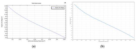
Figure 1.
Volt–ampere characteristics for hydrogen fuel. (a) SOFC model data; (b) manufacturer’s data.
The volt–ampere characteristics for methane and synthesis gas are shown in Figure 2a,b. At the same voltage, the maximum current density is reached for hydrogen fuel (0.22 A/cm2 at 0.6V), then it decreases slightly for synthesis gas (0.2 A/cm2 at 0.6V), and the lowest current density is observed for methane (0.17 A/cm2 at 0.6V). These obtained results are consistent with the data on the net calorific value of the fuel (Table 4).
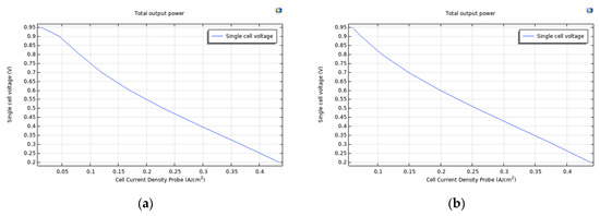
Figure 2.
Volt–ampere characteristics of the SOFC (a) for methane and (b) for synthesis gas.
Table 4.
The calculated parameters of the SOFC operation efficiency for various types of fuel.
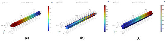
Figure 3.
Distribution of (a) hydrogen; (b) oxygen; and (c) water through the channels when hydrogen is supplied as a fuel.
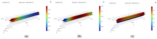
Figure 4.
Distribution of (a) methane; (b) hydrogen; and (c) water through the channels when methane is supplied as a fuel.
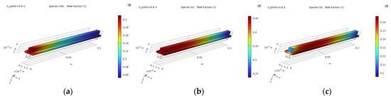
Figure 5.
Gas distribution of (a) methane; (b) hydrogen; and (c) carbon monoxide through the channels when synthesis gas is supplied as a fuel.
When methane is supplied as a fuel, a steam reforming reaction occurs. Hydrogen is formed at the anode, which increases towards the center of the channel and then is consumed in an electrochemical reaction with oxygen (Figure 4). Water is supplied together with methane. Therefore, there is a large amount of water at the beginning of the channel and at the end, as a product of the electrochemical reaction.
When synthesis gas is used as a fuel, the reactions of steam reforming, carbon monoxide oxidation, and the interaction of hydrogen with oxygen occur simultaneously.
Hydrogen is supplied in a sufficiently large amount in the fuel mixture, and is also formed as a result of steam reforming. Therefore, a large amount of hydrogen is observed up to the middle of the channel, then it begins to be consumed in the electrochemical reaction (Figure 5). Carbon monoxide also enters the fuel mixture and reacts with oxygen to form carbon dioxide.
Table 4 presents the calculated parameters of the SOFC operation efficiency on various types of fuel.
According to the results of the study, the highest electrical efficiency can be obtained when operating the SOFC with hydrogen. Synthesis gas obtained by reforming industrial waste also shows good results in terms of efficiency, fuel consumption, and reagent utilization due to its high content of hydrogen, methane, and carbon monoxide.
The ratio of steam to methane is 1.7. The obtained value is within the range of acceptable values indicated in the literature (1.7–2.5) in which no carbon deposits are observed. In the case of using synthesis gas, additional water is formed in the reaction of hydrogen with oxygen, which can also be used for methane reforming.
The heat generated by the fuel cell can be used for pre-reforming or for hybridization of the cycle with other power plants. The largest amount of heat can be obtained by using methane as a fuel.
4. Conclusions
The authors present a model of the SOFC membrane–electrode module, which takes into account the influence of hydro-gas dynamics and mass transfer and the effects of electrochemical and thermal transfers in the cell structure. The mathematical model includes interconnected equations of momentum, mass, heat, and charge transfers; electrochemical reactions; and reforming reactions. Model verification and validation are provided by experimental data. The numerical stability and simulation capabilities of this multiphysics model are provided by the computational grid, which consists of 2.2 million cells. The paper provides detailed information on the distribution of chemical flows, temperature, current density, etc. With the help of numerical simulations, the influence of various types of fuel on the efficiency of the SOFC was studied. It is shown that fuel from petrochemical waste has high electrical and thermal efficiencies with an average consumption of reagents and a high fuel utilization factor.
Author Contributions
Conceptualization, A.F. and I.B.; methodology, A.F.; software, A.P.; validation, A.V., A.G. and A.F.; formal analysis, A.F.; investigation, I.I.; resources, A.F. and I.I.; data curation, I.I.; writing—original draft preparation, A.F.; writing—review and editing, I.I.; visualization, A.V.; supervision, I.I.; project administration, A.F.; funding acquisition, A.F. All authors have read and agreed to the published version of the manuscript.
Funding
Ministry of Science and Higher Education of the Russian Federation “Study of processes in a fuel cell-gas turbine hybrid power plant” (project code: FZSW-2022-0001) by Grant No. BG05M2OP001-1.002-0011-C02 financed by the Science and Education for Smart Growth Operational Program (2014–2020) and co-financed by the European Union through the European Structural and Investment funds.
Institutional Review Board Statement
Not applicable.
Informed Consent Statement
Not applicable.
Data Availability Statement
Not applicable.
Acknowledgments
The results were obtained with the financial support of Ministry of Science and Higher Education of the Russian Federation “Study of processes in a fuel cell-gas turbine hybrid power plant” (project code: FZSW-2022-0001). This work was accomplished with financial support by grant no. BG05M2OP001-1.002-0011-C02 financed by the Science and Education for Smart Growth Operational Program (2014-2020) and co-financed by the European Union through the European Structural and Investment funds. This work has been accomplished with financial support by Grant No BG05M2OP001-1.002-0011-C02 financed by the Science and Education for Smart Growth Operational Program (2014-2020) and co-financed by the European Union through the European Structural and Investment funds.
Conflicts of Interest
The authors declare no conflict of interest.
References
- Iliev, I.K.; Filimonova, A.A.; Chichirov, A.A.; Chichirova, N.D.; Pechenkin, A.V.; Vinogradov, A.S. Theoretical and Experimental Studies of Combined Heat and Power Systems with SOFCs. Energies 2023, 16, 1898. [Google Scholar] [CrossRef]
- Hussain, J.; Ali, R.; Akhtar, N.; Jaffery, M.; Shakir, I.; Raza, R. Modeling and simulation of planar SOFC to study the electrochemical properties. Curr. Appl. Phys. 2020, 20, 660–672. [Google Scholar] [CrossRef]
- Andersson, M.; Yuan, J.; Sundén, B. SOFC modeling considering electrochemical reactions at the active three phase boundaries. Int. J. Heat Mass Transf. 2012, 55, 773–788. [Google Scholar] [CrossRef]
- Ilbas, M.; Kumuk, B. Numerical modelling of a cathode-supported solid oxide fuel cell (SOFC) in comparison with an electrolyte-supported model. J. Energy Inst. 2019, 92, 682–692. [Google Scholar] [CrossRef]
- İlbaş, M.; Kümük, B. Modeling and analysis of a model solid oxide fuel cell running on low calorific value coal gases. Int. J. Hydrogen Energy 2020, 45, 3577–3583. [Google Scholar] [CrossRef]
- Amedi, H.; Bazooyar, B.; Pishvaie, M. Control of anode supported SOFCs (solid oxide fuel cells): Part I. mathematical modeling and state estimation within one cell. Energy 2015, 90, 605–621. [Google Scholar] [CrossRef]
- Yang, B.; Wang, J.; Zhang, M.; Shu, H.; Yu, T.; Zhang, X.; Yao, W.; Sun, L. A state-of-the-art survey of solid oxide fuel cell parameter identification: Modelling, methodology, and perspectives. Energy Convers. Manag. 2020, 213, 112856. [Google Scholar] [CrossRef]
- Horr, S.; Mohcene, H.; Bouguettaia, H.; Moussa, H. Performance analysis of AS-SOFC fuel cell combining single and sinusoidal flow field: Numerical study. Renew. Energy Environ. Sustain. 2021, 6, 18. [Google Scholar] [CrossRef]
- Błesznowski, M.; Sikora, M.; Kupecki, J.; Makowski, Ł.; Orciuch, W. Mathematical approaches to modelling the mass transfer process in solid oxide fuel cell anode. Energy 2022, 239, 121878. [Google Scholar] [CrossRef]
- Pongratz, G.; Subotić, V.; Hochenauer, C.; Scharler, R.; Anca-Couce, A. Solid oxide fuel cell operation with biomass gasification product gases: Performance- and carbon deposition risk evaluation via a CFD modelling approach. Energy 2022, 244, 123085. [Google Scholar] [CrossRef]
- Kalra, P.; Garg, R.; Kumar, A. Parametric sensitivity analysis for a natural gas fueled high temperature tubular solid oxide fuel cell. Heliyon 2020, 6, e04450. [Google Scholar] [CrossRef] [PubMed]
- Kim, D.; Bae, Y.; Lee, S.; Son, J.; Shim, J.; Hong, J. Thermal analysis of a 1-kW hydrogen-fueled solid oxide fuel cell stack by three-dimensional numerical simulation. Energy Convers. Manag. 2020, 222, 113213. [Google Scholar] [CrossRef]
- Li, P.; Chyu, M. Simulation of the chemical/electrochemical reactions and heat/mass transfer for a tubular SOFC in a stack. J. Power Sources 2003, 124, 487–498. [Google Scholar] [CrossRef]
- Filimonova, A.; Chichirov, A.; Chichirova, N.; Pechenkin, A. Overview of design diagrams for solid oxide fuel cell and gas turbine hybrid systems for combined heat and power generation. J. Sib. Fed. Univ. Eng. Technol. 2022, 15, 812–834. [Google Scholar]


Disclaimer/Publisher’s Note: The statements, opinions and data contained in all publications are solely those of the individual author(s) and contributor(s) and not of MDPI and/or the editor(s). MDPI and/or the editor(s) disclaim responsibility for any injury to people or property resulting from any ideas, methods, instructions or products referred to in the content. |
© 2023 by the authors. Licensee MDPI, Basel, Switzerland. This article is an open access article distributed under the terms and conditions of the Creative Commons Attribution (CC BY) license (https://creativecommons.org/licenses/by/4.0/).