Abstract
This research presents a comparative analysis of the two important design methodologies involved in developing microelectromechanical system (MEMS) vibrating ring gyroscopes, namely, internal and external ring gyroscopes. Internal ring gyroscopes are constructed with the outside placement of support pillars connected with the semicircular beams that are attached to the vibrating ring structure. The design importance of this particular setting effectively isolates the vibrating ring structure from any external mechanical vibrations, significantly improving the gyroscope’s performance. The internal ring structure provides exceptional precession and reliability, making this design an ideal candidate for harsh conditions, as they can sustain substantial amounts of unwanted and external vibrations without degrading the performance of the gyroscope. On the other hand, external ring gyroscopes include the placement of the support pillars within the vibrating ring structure. This particular design setting is quite convenient in terms of fabrication and provides higher gyroscopic sensitivity. However, this design may lead to coupling of the vibrational modes and potentially compromise the performance of the gyroscope. This research discusses and compares the findings of a modal analysis of the two distinguished design approaches for the MEMS vibrating ring gyroscopes.
1. Introduction
Microelectromechanical system (MEMS) inertial sensors have emerged as essential components of inertial measurement units (IMUs) and have experienced substantial proliferation in the field of space applications. The utilisation of MEMS vibrating ring gyroscopes [1,2,3,4,5,6] has been the subject of substantial discourse in the realm of research and development, particularly in the context of space applications [7,8,9]. There are various other uses for MEMS vibrating ring gyroscopes in contemporary electrical systems. In the realm of smartphone technology, the utilisation of inertial sensors that rely on MEMS vibrating gyroscopes has become increasingly prevalent. The utilisation of this technology enhances the detection of angular movement in digital cameras, while also finding applications in other industries such as biomedical, missile technology, and rollover detections in automotive applications.
MEMS vibrating ring gyroscopes have favourable characteristics for their utilisation in IMUs within space applications due to their symmetrical configuration, exceptional precision, and resilience in challenging environmental conditions [10,11]. The gyroscope’s ring-shaped form, using semicircular springs, exhibits a symmetrical construction that enables it to withstand challenging environmental conditions and high-vibration industries [12,13]. This work aims to analyse a comparative design study on two different designs for MEMS vibrating ring gyroscope. This paper presents the comparative design methodology and early design modelling of the vibrating ring gyroscope. The present study focuses on the examination of modal analysis pertaining to the proposed vibrating ring gyroscope design.
2. Design Methodology
In order to improve performance and stability and decouple vibrational modes, the frame structures of MEMS vibrating ring gyroscopes are important design considerations. There are, in particular, two types of frame structures, the inner ring gyroscope design and the outer ring gyroscope design. Both of the mentioned design frames will be discussed in detail below.
2.1. Internal Ring Gyroscope
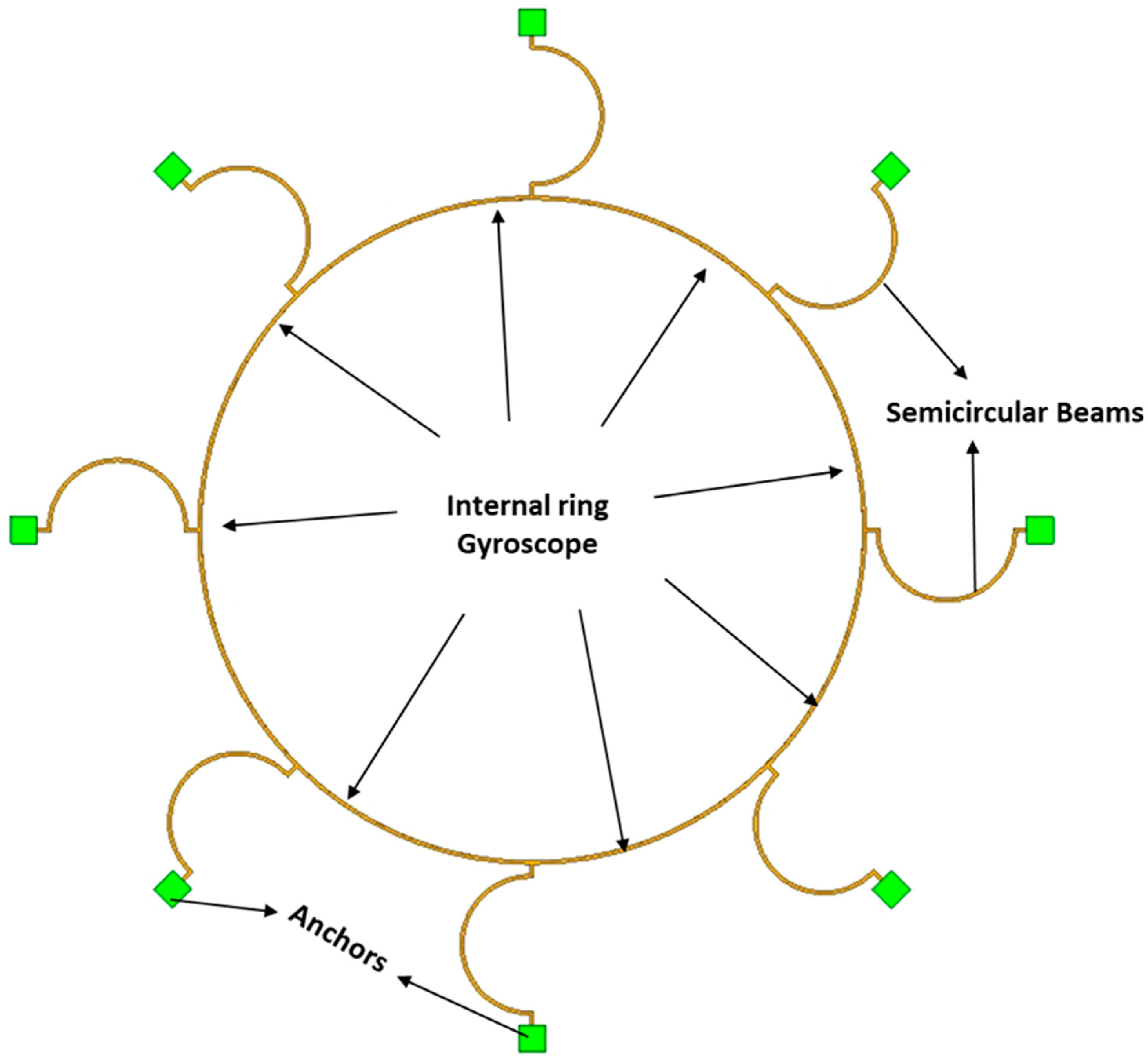
In this type of design frame, the anchor support is designed outside of the vibrating ring structure. The vibrating ring structure is attached with the semicircular beams and the whole vibrating structure is attached to the pillars placed outside. This design configuration of an interior ring has the ability to improve the performance of the gyroscope by protecting the vibrating structure from any disruptive external vibrations. Because of their symmetric structure, inertial sensors with internal vibrating ring gyroscopes are indispensable in extreme conditions. They can withstand extreme conditions and vibrations, making them ideal inertial sensors for use in spacecraft applications. A schematic depiction of the internal ring gyroscope structure is shown in Figure 1.
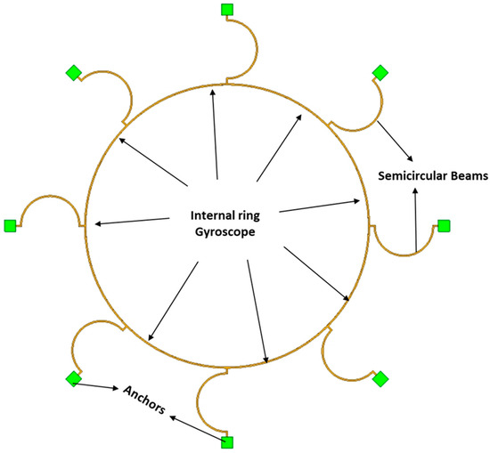
Figure 1.
A schematic representation of the internal ring gyroscope.
2.2. External Ring Gyroscope
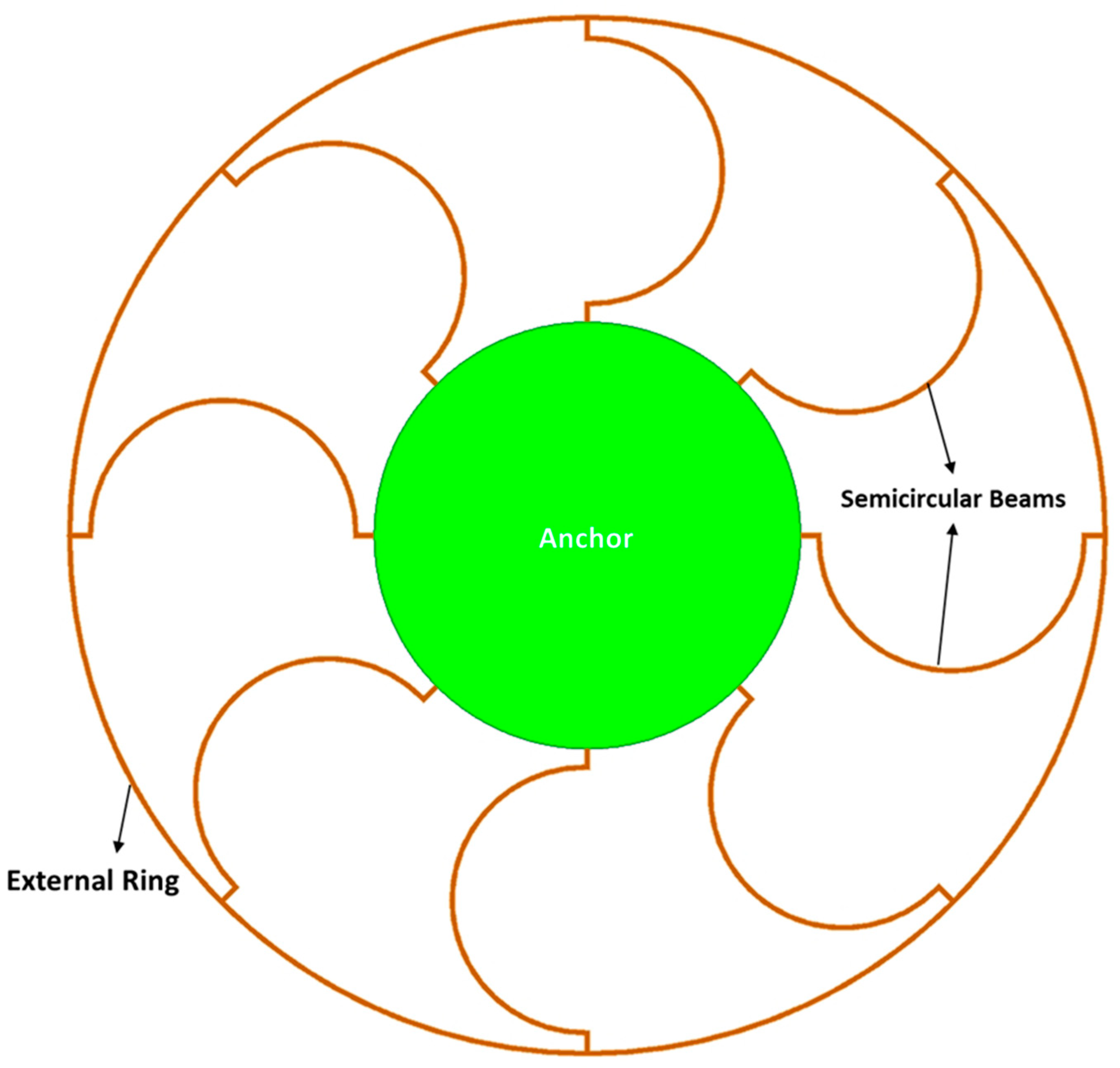
When designing and developing MEMS vibrating ring gyroscopes, it is usual practice to incorporate an external ring design structure. The external ring gyroscope is designed with the support anchor and semicircular beam construction integrated into its interior. This design strategy has the advantage of being able to handle bigger vibrating ring gyroscope structures, which significantly improves the gyroscope’s overall sensitivity. However, unlike the internal ring gyroscope design, this method of design has various difficulties, most notably in terms of its resilience under extreme conditions and its heightened sensitivity to unwanted external vibrations. The external ring gyroscope is shown in Figure 2.
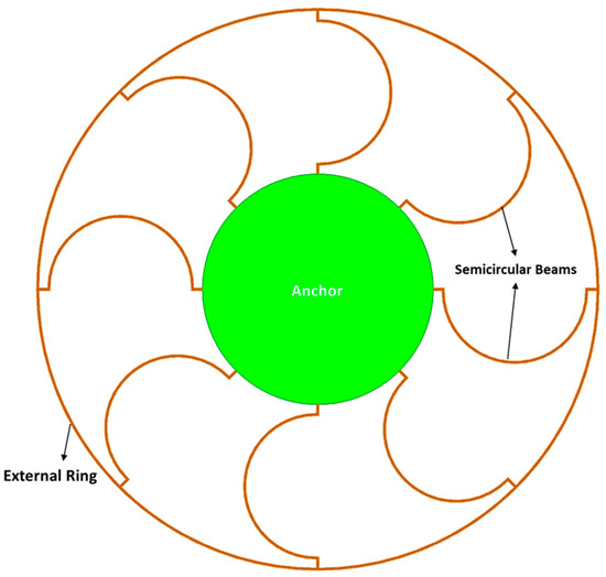
Figure 2.
A schematic representation of the external ring gyroscope.
Internal and external ring gyroscopes can be used in a wide variety of vibrating ring gyroscope configurations. A few examples of these design configurations are gyroscopes with one or more rings, resonator discs, cylinders, shells, and stars. The external ring gyroscope can fit any of these gyroscope designs due to its flexible construction. Single ring gyroscopes, on the other hand, provide many benefits due to their internal design structure. Internal space in the internal ring gyroscope could be utilised for the installation of extra tuning electrodes or the planning and implementation of a microscale inertial sensor.
3. Simulation Analyses
The utilisation of finite element method (FEM) modal analysis is of utmost importance in computational analyses, particularly in the determination of vibration characteristics pertaining to mechanical structures such as the MEMS vibrating ring gyroscope. This methodology facilitates a comprehensive analysis of the dynamics and modal characteristics shown by the vibrating ring gyroscope. The modal analysis offers a comprehensive understanding of the vibrational modes and frequencies of a vibrating ring gyroscope structure. This is achieved by discretising the structure into finite elements and solving the resulting equations. The modal analysis using the FEM based software AnsysTM has been conducted for both internal and external vibrating ring gyroscopes.
3.1. Modal Analysis of Internal Ring Gyroscope
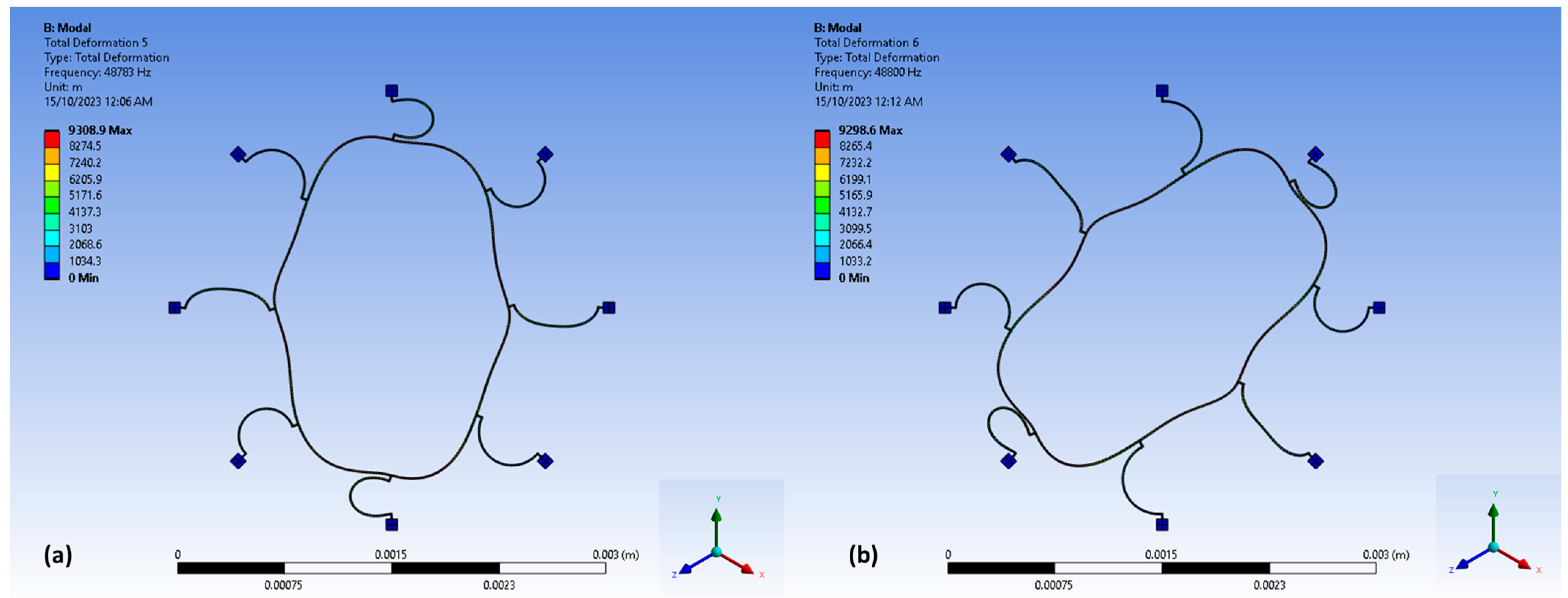
The modal analysis of the internal ring gyroscope is conducted based on its distinctive structural alteration. The design comprises a total of eight semicircular beams, all of which are connected to the internal ring resonator. The entirety of the vibrating ring structure is upheld by externally positioned support pillars around the vibrating structure. The presented design technique effectively implements measures to isolate the vibrating ring structure from potential external disturbances that may have adverse effects on the overall performance of the gyroscope. The design features comprise several key parameters. These include a ring radius of 1000 µm, a semicircular beam radius of 200 µm, a ring and beam thickness of 10 µm, and a structural height of 100 µm. The frequencies depicted in Figure 3 for the internal ring design are 48.78 kHz and 48.80 kHz for mode 1 and mode 2, respectively. The mode mismatch recorded only 17 Hz, which shows a good prospect of high sensitivity. The modal results are shown in Figure 3.
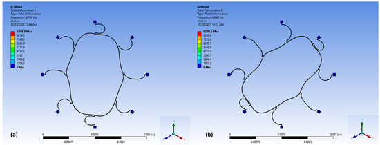
Figure 3.
The modal analysis for the internal ring gyroscope: (a) driving elliptical shape; (b) sensing elliptical shape.
3.2. Modal Analysis of External Ring Gyroscope
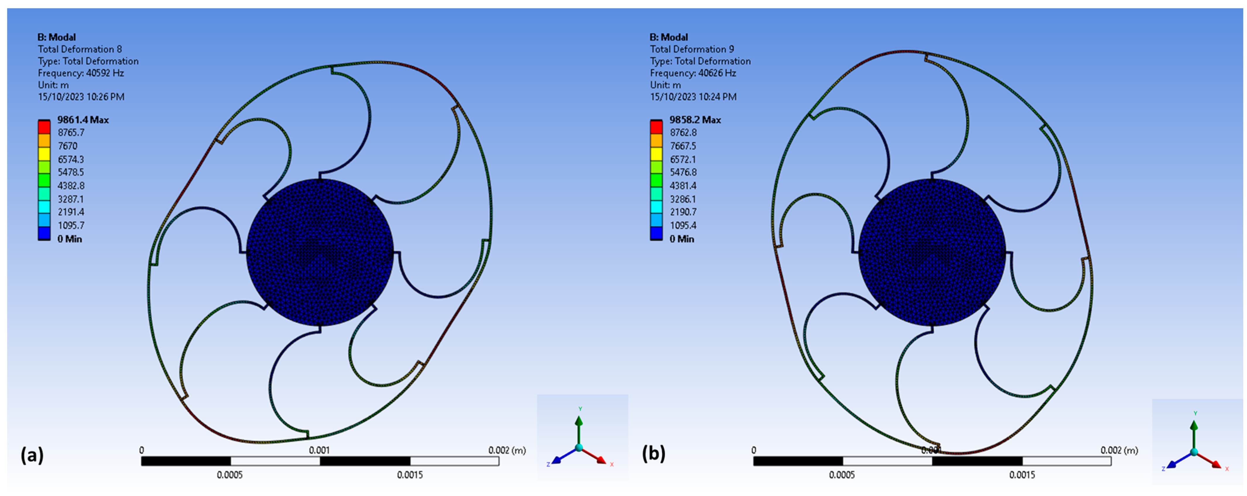
In contrast, the external ring gyroscope exemplifies a conventional methodology for the vibrating ring gyroscope design. The external ring gyroscope exhibits the presence of eight semicircular beams that are connected to the external ring resonator, and the entire vibrating structure is interconnected to the centrally positioned circular pillar. The design features include a ring radius measuring 1000 µm, a semicircular beam radius of 200 µm, thicknesses of 10 µm for both the ring and the beams, and the structure has a height of 100 µm. The modal resonance frequency results are illustrated in Figure 4, with mode 1 exhibiting a resonance frequency of 40.59 kHz and mode 2 displaying a resonance frequency of 40.63 kHz. The mode mismatch recorded 34 Hz, which is slightly higher than the internal ring gyroscope design.
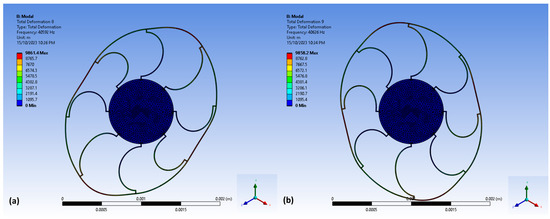
Figure 4.
The modal analysis for the external ring gyroscope: (a) driving elliptical shape; (b) sensing elliptical shape.
Both designs possess identical design characteristics, with the exception being the design geometry. The radii of the vibrating ring and the semicircular beams are same in both gyroscopes. However, it is observed that the internal ring gyroscope exhibited elliptical vibrations at a frequency of around 49 kHz, whereas the external ring gyroscope displayed elliptical vibrations at a frequency of 40 kHz. The mode mismatches for the internal and external ring gyroscopes are observed at frequencies of 17 Hz and 34 Hz, as seen in Table 1. The results indicate that the internal ring gyroscope exhibits higher sensitivity and low mode mismatch between elliptical shapes of vibrations, rendering it a preferable candidate over the external ring design for vibrating ring gyroscopes.

Table 1.
Modal analysis results for internal and external ring gyroscope.
4. Conclusions
We have successfully demonstrated two design types of MEMS vibrating ring gyroscopes, the internal ring and the external ring gyroscope. Comparatively, the internal ring vibrating gyroscope with its outer pillar support shows a good stability against harsh environments. This makes it notably suitable for spacecraft applications. On the other hand, the external ring gyroscope with its centrally positioned pillar offers higher flexibility in design structure but with reduced robustness against high-vibration environments. The FEM modal analysis shows differences in the vibrational mode frequencies of both designs. Despite having identical design features, the internal ring gyroscope demonstrated higher sensitivity with higher resonance frequency responses. The mode mismatch was observed to be just 17 Hz, in contrast to the 34 Hz for the external ring gyroscope. Therefore, the internal ring gyroscope emerges as the more favourable candidate for our further research on gyroscopes.
Author Contributions
The research idea was proposed by W.A.G. and subsequently examined in collaboration with K.M. and W.A.G. conducted all aspects of the research project, including data collection, analysis, and the creation of graphic representations. The manuscript was written by W.A.G. The final manuscript was edited and reviewed by I.H., I.M. and K.M. All authors have read and agreed to the published version of the manuscript.
Funding
This research received no external funding.
Institutional Review Board Statement
Not applicable.
Informed Consent Statement
Not applicable.
Data Availability Statement
Data are contained within the article.
Conflicts of Interest
The authors declare no conflicts of interest.
References
- Yoon, S.W.; Lee, S.; Najafi, K. Vibration sensitivity analysis of MEMS vibratory ring gyroscopes. Sens. Actuators A Phys. 2011, 171, 163–177. [Google Scholar] [CrossRef]
- Cao, H.; Liu, Y.; Kou, Z.; Zhang, Y.; Shao, X.; Gao, J.; Huang, K.; Shi, Y.; Tang, J.; Shen, C.; et al. Design, fabrication and experiment of double U-beam MEMS vibration ring gyroscope. Micromachines 2019, 10, 186. [Google Scholar] [CrossRef] [PubMed]
- Ayazi, F.; Najafi, K. A HARPSS polysilicon vibrating ring gyroscope. J. Microelectromech Syst. 2001, 10, 169–179. [Google Scholar] [CrossRef]
- Gill, W.A.; Howard, I.; Mazhar, I.; McKee, K. A Review of MEMS Vibrating Gyroscopes and Their Reliability Issues in Harsh Environments. Sensors 2022, 22, 7405. [Google Scholar] [CrossRef] [PubMed]
- Jia, J.; Ding, X.; Qin, Z.; Ruan, Z.; Li, W.; Liu, X.; Li, H. Overview and analysis of MEMS Coriolis vibratory ring gyroscope. Measurement 2021, 182, 109704. [Google Scholar] [CrossRef]
- Hyun An, B.; Gill, W.A.; Lee, J.S.; Han, S.; Chang, H.K.; Chatterjee, A.N.; Choi, D.S. Micro-electromechanical vibrating ring gyroscope with structural mode-matching in (100) silicon. Sens. Lett. 2018, 16, 548–551. [Google Scholar] [CrossRef]
- Kou, Z.; Liu, J.; Cao, H.; Han, Z.; Sun, Y.; Shi, Y.; Ren, S.; Zhang, Y. Investigation, modeling, and experiment of an MEMS S-springs vibrating ring gyroscope. J. Micro/Nanolithography MEMS MOEMS 2018, 17, 015001. [Google Scholar] [CrossRef]
- Gill, W.A.; Ali, D.; An, B.H.; Syed, W.U.; Saeed, N.; Al-shaibah, M.; Elfadel, I.M.; Al Dahmani, S.; Choi, D.S. MEMS multi-vibrating ring gyroscope for space applications. Microsyst. Technol. 2020, 26, 2527–2533. [Google Scholar] [CrossRef]
- Dussy, S.; Durrant, D.; Moy, A.; Perriault, N.; Celerier, B. (Eds.) MEMS gyros for space applications-overview of european activities. In Proceedings of the AIAA Guidance, Navigation, and Control Conference and Exhibit, San Francisco, CA, USA, 15–18 August 2015. [Google Scholar]
- Chikovani, V.V.; Tsiruk, H.V. Digital rate MEMS vibratory gyroscope modeling, tuning and simulation results. Comput. Sist. 2017, 21, 147–159. [Google Scholar] [CrossRef]
- Khan, I.; Ting, D.S.; Ahamed, M.J. Design and development of a MEMS vibrating ring resonator with inner rose petal spring supports. Microsyst. Technol. 2021, 27, 985–995. [Google Scholar] [CrossRef]
- Kou, Z.; Liu, J.; Cao, H.; Shi, Y.; Ren, J.; Zhang, Y. A novel MEMS S-springs vibrating ring gyroscope with atmosphere package. AIP Adv. 2017, 7, 125301. [Google Scholar] [CrossRef]
- Gill, W.A.; Howard, I.; Mazhar, I.; McKee, K. Design and Considerations: Microelectromechanical System (MEMS) Vibrating Ring Resonator Gyroscopes. Designs 2023, 7, 106. [Google Scholar]
Disclaimer/Publisher’s Note: The statements, opinions and data contained in all publications are solely those of the individual author(s) and contributor(s) and not of MDPI and/or the editor(s). MDPI and/or the editor(s) disclaim responsibility for any injury to people or property resulting from any ideas, methods, instructions or products referred to in the content. |
© 2023 by the authors. Licensee MDPI, Basel, Switzerland. This article is an open access article distributed under the terms and conditions of the Creative Commons Attribution (CC BY) license (https://creativecommons.org/licenses/by/4.0/).

