Abstract
Magnetic nanofibers can be fabricated by adding nanoparticles in polymer solution using electrospinning method. The advantages of such nanofibers include a large surface-to-volume ratio and high porosity, which makes them promising for sensing applications. In addition, carbonization of such nanofibers increases electrical conductivity. In this study, the chemical and morphological properties of magnetic nanofiber mats prepared from polyacrylonitrile (PAN)/magnetite and carbonized at 500 °C, 600 °C, 800 °C, and 1000 °C were measured. Resulting surface morphologies with some agglomerations are discussed. Addition of nanoparticles increased average fiber diameter and improved dimensional stability.
1. Introduction
Magnetic nanofibers are produced by introducing magnetic nanoparticles into a polymer solution using an electrospinning process, which is simple and cost-effective [1,2]. Due to their high surface-to-volume ratio and high porosity, nanofibers have excellent sensitivity and high sensing performance, which makes them attractive for sensing applications such as detection of various gases, strain sensors, etc. [3,4]. Electrospinning is a very efficient and versatile method for the manufacture of nanofibers on a large scale and at low cost [5,6,7]. Magnetic nanofibers are of great interest for basic research of their magnetic properties as well as for possible applications in spintronics or neuromorphic computing [8]. The nanofiber mats produced by electrospinning are widely applied in filtration, separation, sensors, catalyst support, energy storage, biomedicine, etc. Many chemoresistive detectors are prepared using electrospinning methods to obtain easy to produce micrometer-sized detectors with high sensitivity, increased detection rates, stability, and cross sensitivity [9,10,11]. Ali et al. presented the development of an immunosensor based on mesoporous zinc oxide nanofibers (ZnOnFs) for breast cancer screening [12]. Dutta et al. developed an impedimetric biosensor using polyaniline (PANI) nanofibers that were deposited on a gold (Au) electrode using the cyclic voltammetry technique for the detection of Escherichia coli O157:H7 bacteria [13]. Zhang et al. used graphene oxide (GO) nanofibers decorated with nickel oxide (NiO) for the electrochemical detection of glucose [14]. Yilun et al. reported a lateral flow immunosensor based on electrospun cellulose nitrate nanofibers and magnetic nanoparticles (γ-Fe2O3) to detect E.coli O157:H7 colonies [15].
This study deals with electrospun magnetic nanofiber mats of polyacrylonitrile (PAN) and magnetite nanoparticles using the low toxic solvent dimethyl sulfoxide (DMSO). The different nanofiber morphologies of the oxidatively stabilized and carbonized nanofiber mats at 500 °C, 600 °C, 800 °C, and 1000 °C were investigated using CLSM, AFM, and SEM/EDS, and are discussed below.
2. Materials and Methods
The polymer spinning solution contains 14 wt.% polyacrylonitrile (X-PAN, Dralon, Dormagen, Germany) dissolved in DMSO (min 99.9%, purchased from S3 chemicals, Bad Oeynhausen, Germany) and 20% magnetic nanoparticles Fe3O4 (magnetite, 50–10 nm diameter, Merck KGaA, Darmstadt, Germany). The polymer solution was stirred for 2 h on a magnetic stirrer and before electrospinning additionally treated in an ultrasonic bath for 40 min at 35 °C with a frequency of 37 kHz. The needleless electrospinning machine Nanospider Lab (Elmarco, Liberec, Czech Republic) was used. Optical investigations were made with a FlexAFM Axiom (Nanosurf, Liestal, Switzerland) and a confocal laser scanning microscope (CLSM), VK-8710 (Keyence). A Zeiss 1450VPSE scanning electron microscope (SEM) and energy-dispersive X-ray spectroscopy (EDS) were used for more detailed investigations. For Fourier-transform infrared (FTIR) spectroscopy, an Excalibur 3100 (Varian, Inc., Palo Alto, CA, USA) was used.
3. Results and Discussion
Figure 1 shows AFM images of magnetite nanofibers after electrospinning (Figure 1a), stabilization (Figure 1b), and carbonization (Figure 1c). After electrospinning the nanofibers are relatively straight, linked together and some beads are visibleAfter oxidative stabilization at 280 °C (Figure 1b) and carbonization at 600 °C (Figure 1c), the nanofibers exhibit shortening and contraction. In addition, the diameter of the nanofibers decreases and the beads do not disappear and are still visible.
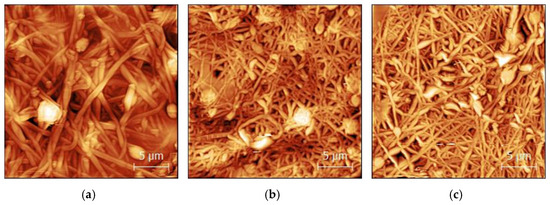
Figure 1.
AFM images of (a) PAN/magnetite nanofiber mat after electrospinning, (b) stabilized at 280 °C, and (c) carbonized at 600 °C. The scale bars indicate 5 μm.
Figure 2 shows the difference in fiber diameters distribution of PAN nanofibers and PAN/magnetite nanofibers.
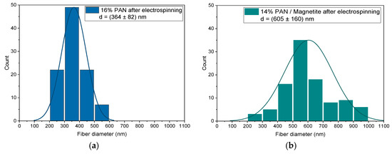
Figure 2.
Distributions of the fiber diameters of (a) pure PAN and (b) PAN/magnetite nanofibers.
The PAN/magnetite nanofiber mats (605 ± 160) nm (Figure 2b) showed a larger average as well as a wider distribution of nanofiber diameters compared to pure PAN (Figure 2a). At this stage, PAN showed a lower average fiber diameter (364 ± 82) nm as well as a narrow distribution of nanofiber diameters. This means that with the addition of magnetite, the nanofiber diameter has increased as is known from previous studies [16,17].
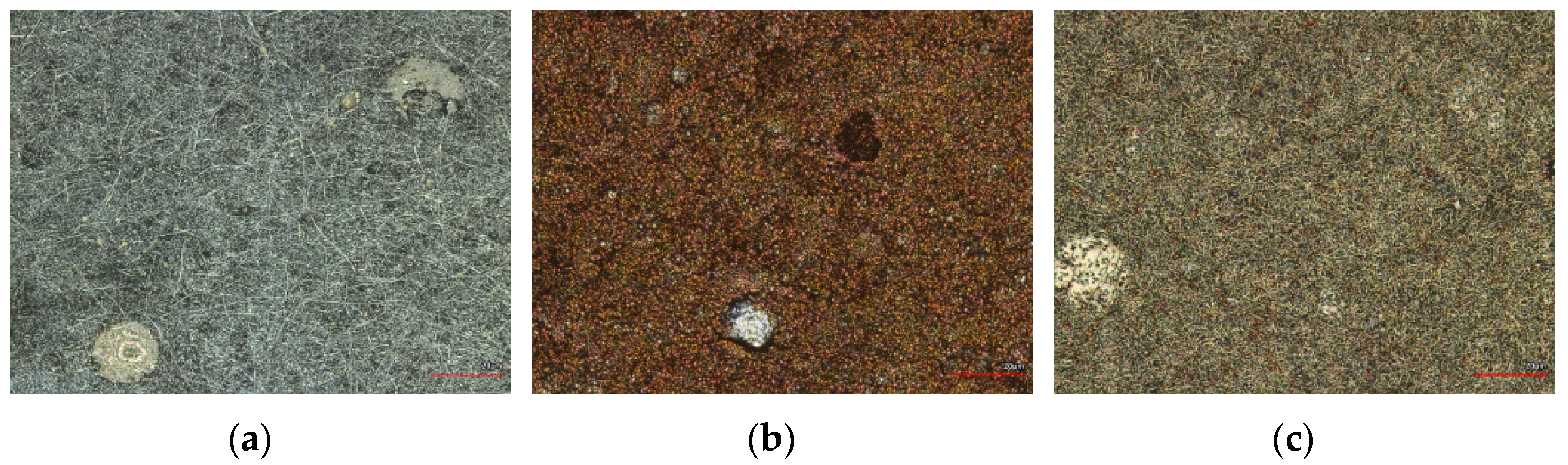
The morphologies of the studied nanofiber mats are shown in the CLSM images in Figure 3. The color change with the increase in temperature and brown color is well visible (see Figure 3b). According to our visual observations from previous studies [18] the color of nanofiber mats changes from white to brown during thermal treatment and to dark brown at 800 °C. In CLSM images, the color change looks different, from light gray (Figure 3a) to brown (Figure 3b) and carbonized nanofiber mats (Figure 3c) look gray with light brown again.
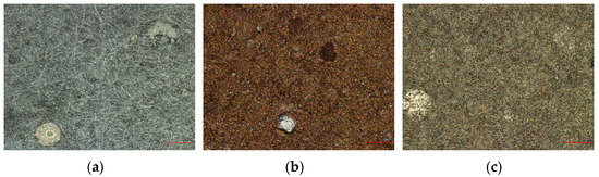
Figure 3.
CLSM images of PAN/magnetite nanofiber mats after electrospinning (a) and after thermal treatment at 600 °C (b) and 800 °C (c). The scale bars indicate 20 μm.
FTIR measurements were performed on the PAN/magnetite nanofiber mats after electrospinning, stabilization, and carbonization at 500 °C, 600 °C, 800 °C, and 1000 °C. The comparison of the spectra shows that the PAN/magnetite mats consists of the typical PAN peaks (not shown here). The significant changes in this region occur during the stabilization and carbonization processes and almost all the peaks disappear at carbonization higher than 800 °C. Below 800 °C, according to our previous studies [19], the carbonization is not complete and peaks are visible.
The SEM images and EDS spectrum clearly show that the highest concentration of particles is located in the beads (see Figure 4).
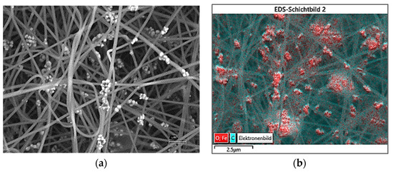
In addition, the EDS spectrum (not shown here) shows strong peaks of the element iron (Fe), confirming that the magnetite nanoparticles are agglomerated within the beads.
4. Conclusions
In this study, PAN/magnetite nanofiber mats were prepared by adding nanoparticles into a polymer solution by the needleless electrospinning method. Oxidative stabilization and carbonization at at 500 °C, 600 °C, 800 °C, and 1000 °C were performed, and the resulting surface morphologies of the nanofiber mats were studied and discussed. According to the study, the addition of nanoparticles increased the fiber average and improved the dimensional stability. Moreover, the agglomeration of magnetite nanoparticles was largely detected in beads by means of SEM and EDS spectra. The results show that more attention should be given to the aspects of the morphological studies, which deals with the effect of thermal treatment on the surface structure of nanofiber mats. The addition of nanoparticles changes the morphology of nanofiber mats. According to the study, agglomeration of magnetic particles are located on the surface and inside the nanofiber mats. New types of nanofiber mats can be manufactured from numerous polymers and different raw materials, which can lead to defined functions and different sensor capacities and still allow for much innovation in the field of sensor technology.
Institutional Review Board Statement
Not applicable.
Informed Consent Statement
Not applicable.
Data Availability Statement
The data created in this study are contained within the article.
Acknowledgments
The authors acknowledge personal funding from the internal PhD funds of Bielefeld University of Applied Sciences, Erasmus+ and the internal funds for female students in STEM programs at Bielefeld University of Applied Sciences.
References
- Storck, J.L.; Grothe, T.; Mamun, A.; Sabantina, L.; Klöcker, M.; Blachowicz, T.; Ehrmann, A. Orientation of Electrospun Magnetic Nanofibers Near Conductive Areas. Materials 2020, 13, 47. [Google Scholar] [CrossRef] [PubMed] [Green Version]
- Döpke, C.; Grothe, T.; Steblinski, P.; Klöcker, M.; Sabantina, L.; Kosmalska, D.; Blachowicz, T.; Ehrmann, A. Magnetic Nanofiber Mats for Data Storage and Transfer. Nanomaterials 2019, 9, 92. [Google Scholar] [CrossRef] [Green Version]
- Trabelsi, M.; Mamun, A.; Klöcker, M.; Sabantina, L.; Großerhode, C.; Blachowicz, T.; Ehrmann, A. Increased Mechanical Properties of Carbon Nanofiber Mats for Possible Medical Applications. Fibers 2019, 7, 98. [Google Scholar] [CrossRef] [Green Version]
- Yu, G.F.; Li, G.T.; Pan, W.; He, X.X.; Zhang, Y.J.; Gong, M.G.; Yu, M.; Zhang, Z.M.; Long, Y.Z. Electromagnetic function-alized ultrafine polymer/γ-Fe2O3 fibers prepared by magnetic-mechanical spinning and their application as strain sensors with ultrahigh stretchability. Compos. Sci. Technol. 2017, 139, 1–7. [Google Scholar] [CrossRef]
- Xue, J.; Wu, T.; Dai, Y.; Xia, Y. Electrospinning and electrospun nanofibers: Methods, materials, and applications. Chem. Rev. 2019, 119, 5298–5415. [Google Scholar] [CrossRef] [PubMed]
- Liu, Q.; Zhu, J.; Zhang, L.; Qiu, Y. Recent advances in energy materials by electrospinning. Renew. Sust. Energ. Rev. 2018, 81, 1825–1858. [Google Scholar] [CrossRef]
- Chen, S.X.; Li, R.Q.; Li, X.R.; Xie, J.W. Electrospinning: An enabling nanotechnology platform for drug delivery and re-generative medicine. Adv. Drug Deliv. Rev. 2018, 132, 188–213. [Google Scholar] [CrossRef] [PubMed]
- Trabelsi, M.; Mamun, A.; Klöcker, M.; Sabantina, L. Investigation of metallic nanoparticle distribution in PAN/magnetic nanocomposites fabricated with needleless electrospinning technique. Commun. Dev. Assem. Text. Prod. 2021, 2, 8–17. [Google Scholar] [CrossRef]
- Rothschild, A.; Komem, Y. The effect of grain size on the sensitivity of nanocrystalline metal-oxide gas sensors. J. Appl. Phys. 2004, 95, 6374–6380. [Google Scholar] [CrossRef]
- Wang, C.; Yin, L.; Zhang, L.; Xiang, D.; Gao, R. Metal oxide gas sensors: Sensitivity and influencing factors. Sensors 2010, 10, 2088–2106. [Google Scholar] [CrossRef] [PubMed] [Green Version]
- Barsan, N.; Weimar, U. Conduction model of metal oxide gas sensors. J. Electroceramics 2001, 7, 143–167. [Google Scholar] [CrossRef]
- Ali, M.A.; Mondal, K.; Singh, C.; Malhotra, B.D.; Sharma, A. Anti-epidermal growth factorreceptor conjugated meso-porous zinc oxide nanofibers for breast cancer diagnostics. Nanoscale 2015, 7, 7234–7245. [Google Scholar] [CrossRef] [PubMed] [Green Version]
- Chowdhury, A.D.; De, A.; Chaudhuri, C.R.; Bandyopadhyay, K.; Sen, P. Label free polyaniline based impedimetric bi-osensor for detection of E. coli O157: H7 Bacteria. Sens. Actuators B Chem. 2012, 171, 916–923. [Google Scholar] [CrossRef]
- Zhang, Y.; Wang, Y.; Jia, J.; Wang, J. Nonenzymatic glucose sensor based on graphene oxide and electrospun NiO nanofibers. Sens. Actuators B Chem. 2012, 171, 580–587. [Google Scholar] [CrossRef]
- Luo, Y.; Nartker, S.; Miller, H.; Hochhalter, D.; Wiederoder, M.; Wiederoder, S. Surface functionalization of electrospun nanofibers for detecting E. coli O157: H7 and BVDV cells in a direct-charge transfer biosensor. Biosens. Bioelectron. 2010, 26, 1612–1617. [Google Scholar] [CrossRef] [PubMed]
- Fokin, N.; Grothe, T.; Mamun, A.; Trabelsi, M.; Klöcker, M.; Sabantina, L.; Döpke, C.; Blachowicz, T.; Hütten, A.; Ehrmann, A. Magnetic Properties of Electrospun Magnetic Nanofiber Mats After Stabilization and Carbonization. Materials 2020, 13, 1552. [Google Scholar] [CrossRef] [PubMed] [Green Version]
- Sabantina, L.; Böttjer, R.; Wehlage, D.; Grothe, T.; Klöcker, M.; García Mateos, F.J.; Rodríguez-Mirasol, J.; Cordero, T.; Ehrmann, A. Morphological study of stabilization and carbonization of PAN/TiO2 nanofiber mats. J. Eng. Fibers Fabr. 2019, 14, 1558925019862242. [Google Scholar]
- Storck, J.L.; Brockhagen, B.; Grothe, T.; Sabantina, L.; Kaltschmidt, B.; Tuvshinbayar, K.; Braun, L.; Tanzli, E.; Hütten, A.; Ehrmann, A. Stabilization and Carbonization of PAN Nanofiber Mats Electrospun on Metal Substrates. C 2021, 7, 12. [Google Scholar] [CrossRef]
- Wortmann, M.; Frese, N.; Mamun, A.; Trabelsi, M.; Keil, W.; Büker, B.; Javed, A.; Tiemann, M.; Moritzer, E.; Ehrmann, A.; et al. Chemical and Morphological Transition of Poly(acrylonitrile)/Poly(vinylidene Fluoride) Blend Nanofibers during Oxidative Stabilization and Incipient Carbonization. Nanomaterials 2020, 10, 1210. [Google Scholar] [CrossRef] [PubMed]


Publisher’s Note: MDPI stays neutral with regard to jurisdictional claims in published maps and institutional affiliations. |
© 2021 by the authors. Licensee MDPI, Basel, Switzerland. This article is an open access article distributed under the terms and conditions of the Creative Commons Attribution (CC BY) license (https://creativecommons.org/licenses/by/4.0/).