Proceeding Paper

Water Tower Base Method for the Optimization of Expansion and Shear during Construction †

Department of Mechanics and Machine Elements, University of Varna, 9000 Varna, Bulgaria
*
Author to whom correspondence should be addressed.
Presented at the International Conference on Electronics, Engineering Physics and Earth Science (EEPES’24), Kavala, Greece, 19–21 June 2024.
Eng. Proc. 2024, 70(1), 4; https://doi.org/10.3390/engproc2024070004
Published: 23 July 2024

Abstract

:
The primary purpose of the present research is to analyze and determine the impact that expansion and shear exert on the production time, expenditures on materials and consumable items, i.e., production costs, and the cost of the manufactured sheet material details. An applied study was, accordingly, conducted to investigate the implications of different design features and shear on a sheet material workpiece, i.e., the base of a water tower, with respect to the shear line produced during surface segmentation. In order to determine in which direction and to what extent the dimensions of the constituent elements influence the expansion, a graphical experiment was performed with a smaller width of the elements than the surrounding surface, as well as with two different steps. Cases are presented and analyzed in which the surrounding surface is considered as composed of several composite belts in horizontal and vertical arrangements of the metal sheets. The research findings refer to the sheet material parameters (thickness, dimensions), production technology principles, and their effects on the technological process to optimize material costs and reduce waste in manufacturing. The study revealed that in order to achieve optimal shear outcomes, it is recommended to manufacture all the segments concurrently, and shorten the time of production by programming the process of shear to minimize the length of the shearing lines while segmenting the surfaces of the relevant details. This will be more suitable in the case of constructions executed along helical lines, applied with a small step, where the residual material is of more compact dimensions with a suitable cut.

1. Introduction

The advancement of information technology is clearly demonstrated in the field of construction, particularly in the utilization of CAD systems to design structures and intricate details. CAD systems play a crucial role in tasks that involve the creation of 3D models, generation of drawings, and documentation production [1]. Thus, in architecture and construction, the primary objective of CAD is to enhance the efficiency of engineering work by automating the process of design and streamlining the preparation of the details to be produced [2,3,4]. Of utmost importance, to that effect, is proficiency in professional decision making and the ability to design optimal solutions using the appropriate techniques and tools for optimal design outcomes embedded in CAD programs.
Sheet metal shearing is a fundamental process in the manufacturing industry, enabling the fabrication of specific shapes and sizes required for various products and components. From household appliances to industrial machinery and construction materials, sheet metal shearing plays a vital role in the production of a wide range of everyday objects [5,6]. Various techniques for expansion and shear offer distinct advantages and are appropriate for particular applications based on factors including precision, type of material, and volume of production. The proper understanding of these methods allows manufacturers to strategically determine the best approach for their individual requirements, thus maximizing efficiency, quality, and profitability [7]. To build a high-quality model, using two phases in each cycle is a good compromise [8,9].
The conversion of shapes into expandable surfaces is a complex and multifaceted endeavor encompassing a variety of methods for segmenting, expanding, and producing shapes with diverse geometry and topology, culminating in the complexity and intricacy of unfolding surfaces [10].
In most cases, shape segmentation is carried out without taking foldability into account [11]. As a result, the surface, generated by shape segmentation can be divided into multiple parts or approximated by multiple unfolding surfaces, leading to a loss of semantic meaning, and making folding and assembly less intuitive and more time-consuming [12]. Segmentation can also be performed to prevent overlapping in the parts [13]. According to Zhonghua Xi et al. [14], the proposed method generates segmentation directly from information obtained from edge unfolding, ensuring that each component in the segmentation can be unfolded into a single part while retaining its semantics.
Despite extensive research on the unfolding surfaces of sheet material products and the segmentation of surfaces in a geometrically optimized mesh [15,16,17,18,19], sufficiently practical and rational decisions for optimizing the workpiece shearing with minimal manufacturing waste have yet to be discovered, and comprehensive data for detailed study in this area are yet to be found.
In the manufacture of sheet material details for various purposes, such as transforming sections for dryers, steel elements in fire-fighting equipment, adaptors of the same shape but different size, different types of hoppers, auger housings, industrial cyclones, fans, pipelines of various cross-sections, parts of equipment and facilities for the needs of agricultural production related to the processing of agricultural produce, cyclones and water towers, determining the lines of mutual intersection of their component parts is a critical task during the design phase [20,21]. Determining the necessary amounts of production materials for machinery and equipment featuring predominantly sheet metal components is vital for single and small-scale production [22,23,24]. The shapes of these technical products are created by combining different geometric solids or parts thereof obtained by their mutual intersection. The intersection of these components of space (surfaces) with each other occurs in planar or spatial curves known as surface sections. Identifying them is crucial for the practical implementation of these products. To obtain them, it is necessary to locate the lines of intersection in order to derive the shapes and dimensions of the surfaces. This is accomplished by constructing the expansions of these products.

2. Material and Method

2.1. Intersection of Solids

Of special interest are the multiple instances of lines intersecting ribbed and rotary solids, as well as adaptors of the same shape and different sizes—particularly with respect to their expansions, as well as straight and conical helicoids, which defy easy classification. This is also applicable to cases where certain Platonic solids, for instance, dodecahedron and icosahedron, intersect with cylindrical and conical surfaces in structures such as water towers as an alternative to the conical and cylindrical segment depicted in Figure 1 or those of approximated spherical surfaces.
It is most efficient to construct the line of mutual intersection of the surfaces, regardless of the type and their mutual location in certain orthogonal projections, according to the following algorithm [24]:
  • Identify the type of the section;
  • Specify the method of constructing the section;
  • Select the type of auxiliary sectional surfaces;
  • Determine the visibility of the section segments and the projections of the intersecting surfaces.

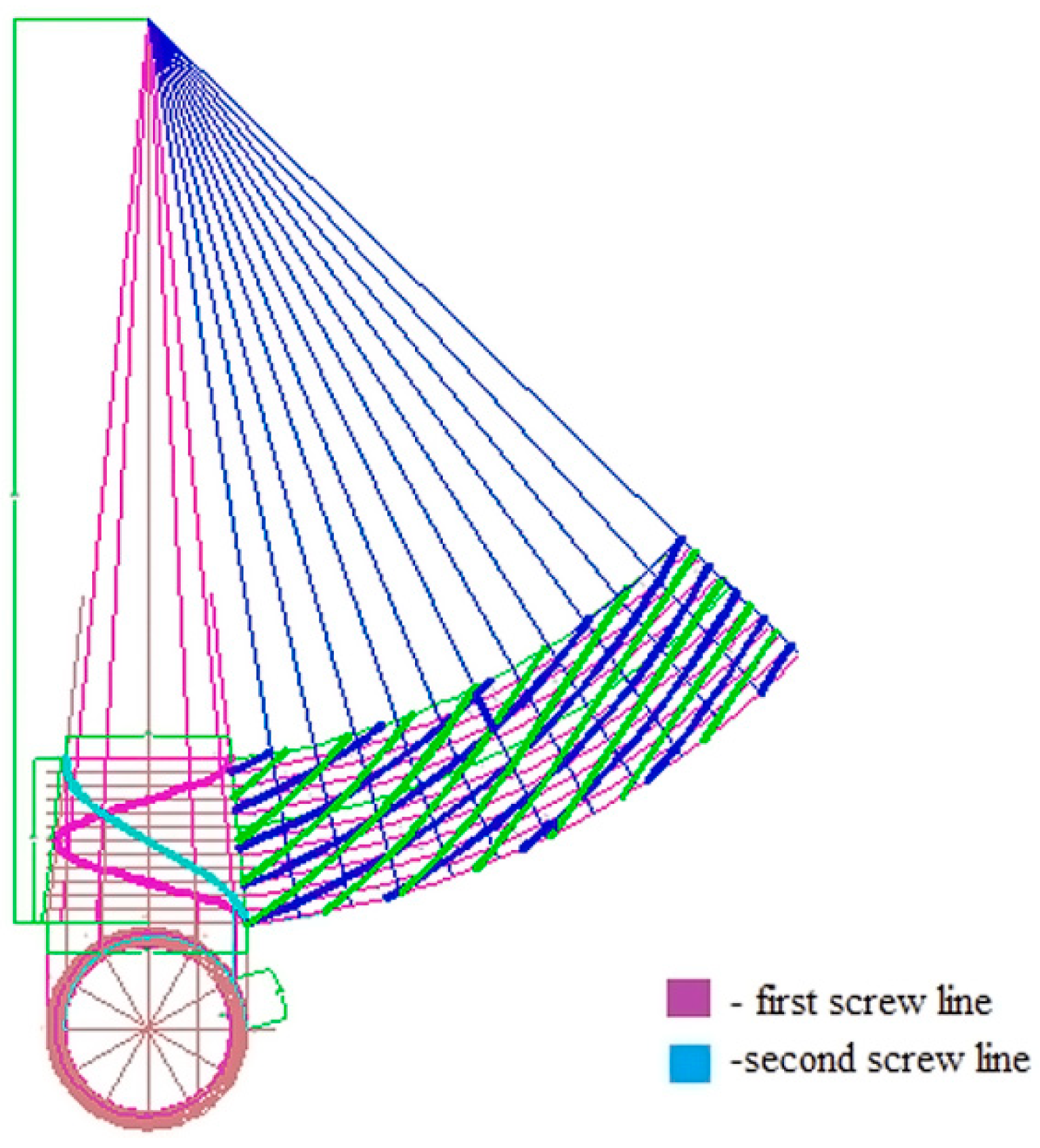
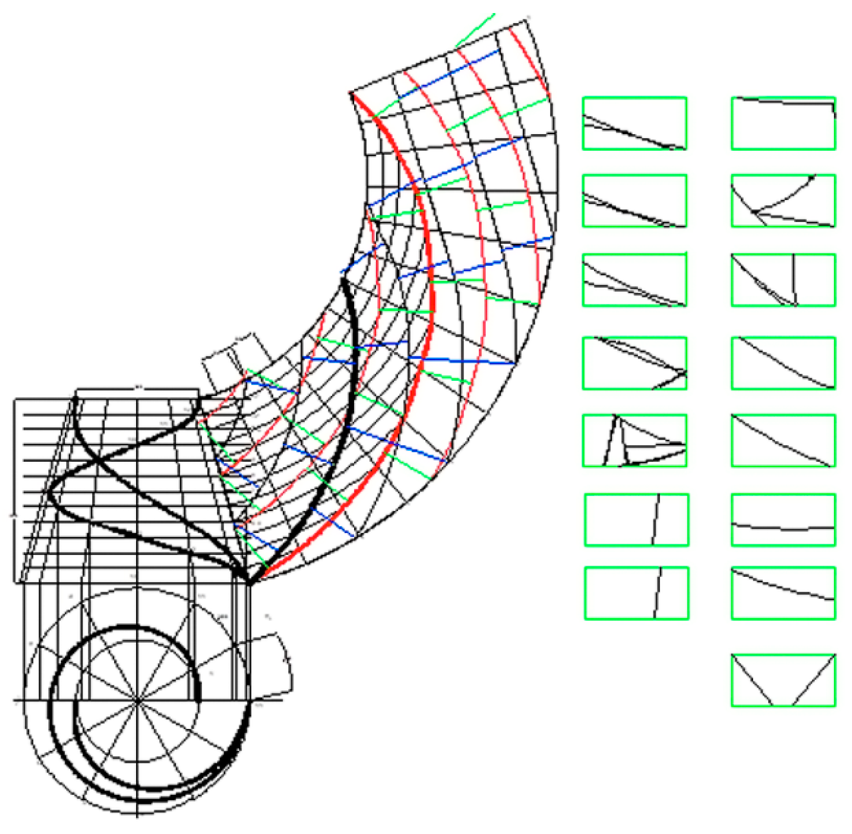
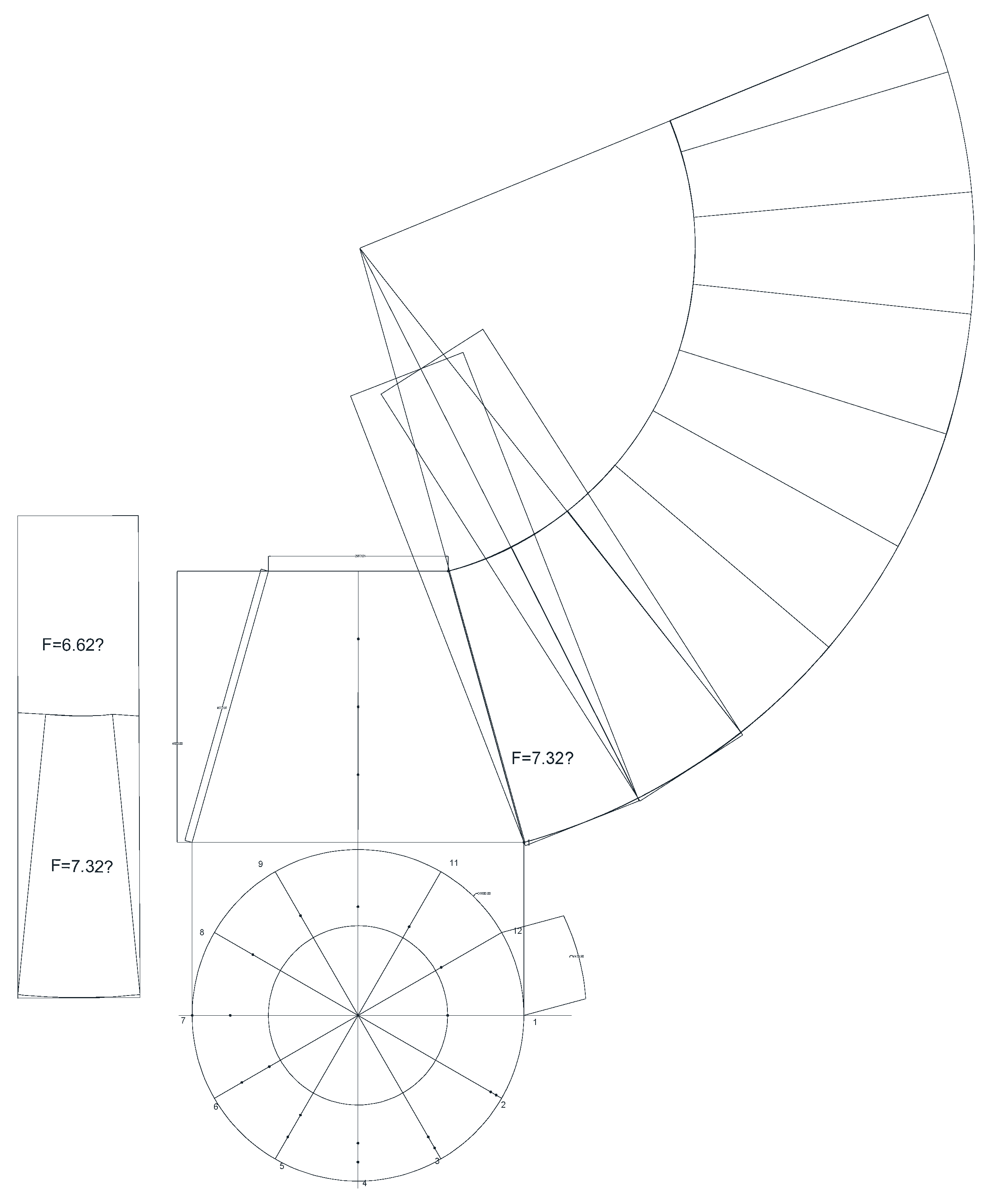
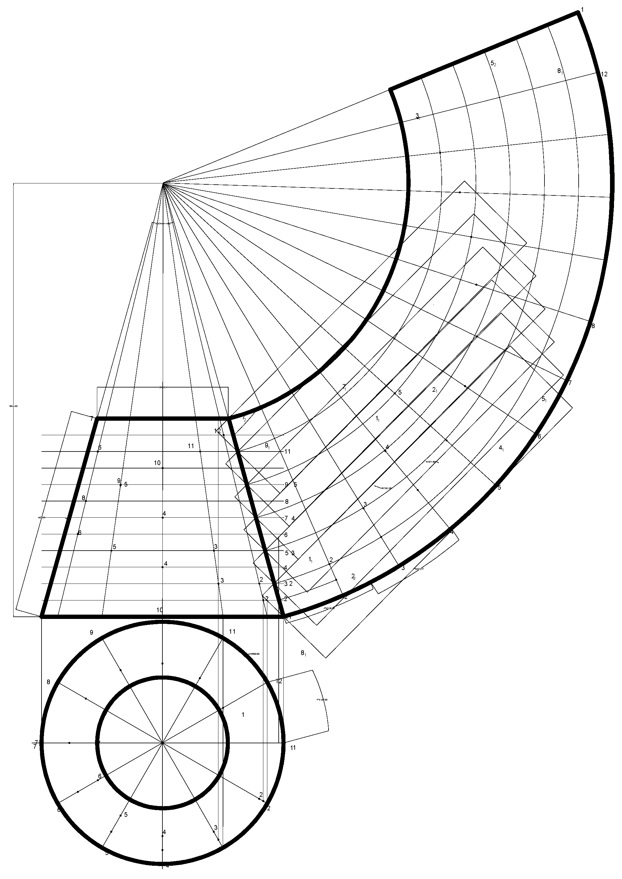
2.2. Expansion and Shear through the Use of a Water Tower

Although the expansion of conical surfaces may not be viewed as complex, it actually offers a wide range of applications and a multitude of technical solutions due to the fact that a substantial portion of the surfaces of large-scale equipment can be obtained precisely through it, as an intrinsic component. In order to conduct a more comprehensive analysis, a specific structure on the basis of a water tower (Figure 1) will be considered. It has the shape of a truncated cone with bases of 5.5 m and 4.5 m, and a height of 4.5 m. Given its large dimensions, several designs of the structure are possible. The metal sheets or large parts of them can be bent and arranged in a helical line wrapping the surrounding surface of the structure, as the unfolding of any conical surface can be achieved on a plane through the method of roll forming, as displayed in Figure 2.
The unfolding of the conical surface and the shearing of sheet material placed along the helical line with two different pitches are illustrated in Figure 3.
To determine the impact of the pitch of the helical line on material consumption, manufacturing waste, and optimal shearing, two helical lines with different pitches are constructed. One of the helical lines is depicted in Magenta, while the other is in Cyan. Placed along the direction of the helical lines, positioned on the expansion at equal distance (1000 mm via the Offset command), are components of the surrounding surface cut off from metal sheets measuring 2000/8000 mm. The goal in both cases is to utilize a greater number of identical components, if possible, to minimize material consumption. The expanded components are displayed (Figure 3) on the metal sheets positioned as they are during shearing and coded in the same color to match the helical lines.
Figure 4 shows the development of a conical surface and an implementation of sheet material with a small width of 1250 mm.

3. Results and Discussion

It is evident from the drawings and calculations made that accomplishing structures along helical lines is most effective when utilizing a smaller pitch to yield residual material with tighter dimensions and proper shear. All other factors being equal, in one case, 8 sheets of 16 m2 were used, while applied in the other case were 7 sheets, and yet the material consumption remained consistent. However, when considering the length of the shearing line at a smaller half-pitch, it is 154.15 m compared to 145.15 m at one step, and with the corresponding number of cut-off details being 20 and 12 pieces, respectively, it becomes apparent that working with full-pitch sheet material details is more desirable. The greater the length of the shearing line, the greater the material consumption as a result of material loss during shearing. The lost area can be calculated using the following formula:
F   a v e r a g e = L   a v e r a g e . ( d e l + 3 4 ) ,
where F is the area lost in shearing; L average is the length of the shearing line del is the diameter of the plasma cutter electrode; and 3(4) mm is the area of the sheet material around the electrode that melts and needs to be removed.
It is dependent on the electrode diameter and other technical parameters descriptive of the plasma cutting process. In the case under consideration, when the pitch is smaller, F average will be greater by 2.5%. Moreover, the auxiliary and preparatory time required for producing the details will be longer pursuant to the ratio of the number of the details in each case, i.e., almost 1.6 times.
A graphical experiment was conducted to explore the direction and the extent to which the dimensions of the intrinsic components influence expansion when their width is smaller than that of the surrounding surface. To that effect, identical helical lines were constructed on the same surface but offset at a distance of 650 mm. The components themselves were placed on metal sheets of the same size, using criteria consistent with the previous setup. The positioning of the metal sheets is indicated on the expansion itself, allowing for more efficient use of the sheet material with less manufacturing waste, a smaller number of details, i.e., 8 and 7 pieces, respectively, a significantly reduced length of the shear, and a shorter auxiliary and preparatory time required for the manufacturing of the details. Established for comparative purposes are the lengths of the shear only along the contour line of the details cut off from the full width of the sheet for half and one pitch, respectively. Thus, the L   a v e r a g e = 51.01   m and L   a v e r a g e = 55.96   m , and if the shearing is along a bandwidth of 0.6 m, then the L   a v e r a g e = 143.75   m and L   a v e r a g e = 139.02   m , sequentially.
Provided in Figure 5, Figure 6 and Figure 7 is a graphical representation of the results.
As observed in Figure 5, the case under survey involves the use of 6 and 9 sheets of 16 m2, respectively. It can, therefore, be inferred that the expansion is more effective, and that a decrease in the width of the constituent components does not necessarily reduce material consumption, but utilizing the full width of the sheet material in shearing results in a drop in the number of details, in the length of the shearing line, and in the auxiliary and preparatory time required for the manufacturing of the details.
In order to establish the optimal shearing approach, two additional cases were considered and analyzed, i.e., when the metal sheets are located horizontally or vertically. Figure 6 shows the shearing of the sheet material with the sheets placed vertically during expansion. And in Figure 7, elevations they are placed horizontally.
In this case, the number of the details amounts to 10, with 2 having the same area F 1 , 2 having the same area F 2 , 3 having the same area F 3 , and 3 having miscellaneous small details. The length of the shearing line is computed to be L   a v e r a g e = 135.22   m .
In this case, the number of details is nine, of which eight are identical with area F 1 = 7.32   m 2 , and one with area F 1 = 3.52   m 2 . The length of the shear line is L   a v e r a g e = 110.64   m . The length of the shear line in Figure 6 is 33.4% shorter than in Figure 3, and 20.8% shorter than in Figure 4. The number of surface elements in Figure 7 is only 69.4% of the number of elements in Figure 3 and almost the same as that of the elements in Figure 4. A great advantage of the approach to obtaining the surface of Figure 6 is that all elements are the same except for one, while in Figure 3 and Figure 4, all elements are different.

4. Conclusions

Based on the obtained results, the following conclusions can be drawn:
The expansions of the non-expandable surfaces of the second and higher degrees and the transitions between sections of different types and shapes with variable dimensions can be obtained with sufficient accuracy for practice by fitting into them a system of more than 16 sectors (segments) of expandable surfaces.
To optimize the cut, it is recommended to manufacture all segments (sectors) of the inscribed unfolding surfaces together. In order to reduce the production time, it is recommended to program the cutting in order to minimize the cutting line lengths of the segments (sectors) of the inscribed unfolding part surfaces.

Author Contributions

All authors have accepted responsibility for the entire content of this manuscript and consented to it submission to the journal, reviewed all the results and approved the final version of the manuscript. All authors have read and agreed to the published version of the manuscript.

Funding

The authors claim no funding.

Institutional Review Board Statement

The study was conducted in accordance with the Declaration of Helsinki, and approved by the Institutional Review Board.

Informed Consent Statement

Informed consent was obtained from all subjects involved in the study.

Data Availability Statement

Data supporting the reported results and links to publicly archived datasets can be found at the following links: https://ieeexplore.ieee.org/document/9960020 (accessed on 6 March 2024); https://pubs.aip.org/aip/acp/article/2868/1/020022/2906499/Unfolds-of-non-expandable-surfaces-and-some (accessed on 6 March 2024).

Conflicts of Interest

The authors declare no conflicts of interest.

References

  1. Butoruna, I.V.; Vasileva, N. Parametric modeling in architectural and construction design in AutoCAD. IOP Conf. Ser. Mater. Sci. Eng. 2018, 451, 012121. [Google Scholar] [CrossRef]
  2. Egamov, N.M.; Hayitova, I.I. Application of information technologies in designing. Young Sci. 2015, 9, 365–368. [Google Scholar]
  3. Ertskina, E.B.; Korolkova, N.N. Geometric modeling in the automated design of architectural objects. Geom. Graph. 2016, 4, 48–54. [Google Scholar] [CrossRef]
  4. Ovcharenko, O. Mutual support and use of CAD-programs. Geom. Graph. 2016, 4, 64–69. [Google Scholar] [CrossRef]
  5. Sheet Metal Cutting Methods in Manufacturing, Sheet Metal Fabrication. Available online: https://proleantech.com/unfolding-the-sheet-metal-cutting-methods/ (accessed on 6 March 2023).
  6. Unfolding Sheet Metal Component Examples. Available online: https://help.spaceclaim.com/dsm/6.0/en/Discovery/user_manual/sheetmetal/r_unfold_fold-walls_examples.html (accessed on 6 March 2023).
  7. Sheet Metal Rolling, or How to Make Custom-Sized Pipes and Cones. Available online: https://myeusteel.com/sheet-metal-rolling/ (accessed on 6 March 2024).
  8. Nikolova, N.; Rodríguez, R.M.; Symes, M.; Toneva, D.; Kolev, K.; Tenekedjiev, K. Outlier Detection Algorithms Over Fuzzy Data with Weighted Least Squares. Int. J. Fuzzy Syst. 2021, 23, 1234–1256. [Google Scholar] [CrossRef]
  9. Nikolova, N.; Toneva, D.; Tsonev, Y.; Burgess, B.; Tenekedjiev, K. Novel Methods to Construct Empirical CDF for Continu-ous Random Variables using Censor Data. In Proceedings of the IEEE 10th International Conference on Intelligent Systems (IS), Varna, Bulgaria, 28–30 August 2020; pp. 61–68. [Google Scholar] [CrossRef]
  10. Yuan, C.; Cao, N.; Shi, Y. A Survey of Developable Surfaces: From Shape Modeling to Manufacturing. arXiv 2023, arXiv:2304.09587. [Google Scholar] [CrossRef]
  11. Julius, D.; Kraevoy, V.; Sheffer, A. D-charts: Quasi-developable mesh segmentation. Comput. Graph. Forum 2015, 24, 581–590. [Google Scholar] [CrossRef]
  12. Straub, R.; Prautzsch, H. Creating Optimized Cut-Out Sheets for Paper Models from Meshes. Technical Report. Karlsruhe. In Proceedings of the SIAM Conference on Geometric Design and Computing in Phoenix, USA, 2005; pp. 1–15. Available online: https://geom.ivd.kit.edu/downloads/proj-paper-models_cut_out_sheets.pdf (accessed on 6 March 2024).
  13. Katz, S.; Tal, A. Hierarchical mesh decomposition using fuzzy clustering and cuts. ACM Trans. Graph. 2003, 22, 954–961. [Google Scholar] [CrossRef]
  14. Xi, Z.; Kim, Y.; Young, J.K.; Lien, J.-M. Learning to segment and unfold polyhedral mesh from fail-ures. Comput. Graph. 2016, 58, 139–149. [Google Scholar] [CrossRef]
  15. Xing, Q.; Esquivel, G.; Akleman, E. Band decomposition of 2-manifold meshes for physical construction of large structures. In Proceedings of the ACM SIGGRAPH 2011 Posters (SIGGRAPH’11), New York, NY, USA, 7 August 2011; p. 1. [Google Scholar] [CrossRef]
  16. Pottmann, H.; Brell-Cokcan, H.; Wallner, J. Discrete Surfaces for Architectural. In Design. Curves and Surface Design; Avignon Chen, C.-T., Ed.; Nashboro Press: Brentwood, TN, 2007; pp. 213–234. [Google Scholar]
  17. Pottmann, H.; Liu, Y.; Wallner, J.; Bobenko, A.L.; Wang, W. Geometry of Multi-Layer Freeform Structures for Architecture. ACM Trans. Graph. 2007, 26, 65. [Google Scholar] [CrossRef]
  18. Liu, Y.; Pottmann, H.; Wallner, J.; Yang, Y.; Wang, W. Geometric modeling with conical meshes and developable surfaces. ACM Trans. Graph. 2006, 25, 681–689. [Google Scholar] [CrossRef]
  19. Akleman, E.; Kalantar, K.S.; Wu, Y.N.; Borhani, A. Construction of 2-Manifold Surfaces Using Physical Version of Quad-Edge Data Data Structure. Comput. Graph. 2016, 58, 172–183. [Google Scholar] [CrossRef]
  20. Bankova, A.; Tenev, S.; Tsoneva, Z.; Tachev, M.; Mehmedov, I. AutoCAD Application for Selecting the Required Materials for Manufacturing Machines and Equipment from Sheet Material. In Proceedings of the 2022 International Conference Automatics and Informatics (ICAI), Varna, Bulgaria, 6–8 October 2022; pp. 303–306. [Google Scholar] [CrossRef]
  21. Georgiev, G.; Argirov, Y.; Mechkarova, T.; Spasova, D.; Stoyanova, A. Investigation of the occurrence and development of fatigue cracks after corrosion of welded samples of ferritic-austenitic steel. IOP Conf. Ser. Mater. Sci. Eng 2021, 1037, 012037. [Google Scholar] [CrossRef]
  22. Mihaylov, R.; Atanasov, A.; Ivanovа, A.; Marinov, A.; Zahariev, S. Tracking The Development Of Six Wheat Varieties Using Infrared Imaging And Image Processing Algorithms. In Proceedings of the 2020 International Conference Automatics and Informatics (ICAI), Varna, Bulgaria, 1–3 October 2020; pp. 1–5. [Google Scholar] [CrossRef]
  23. Mihaylov, R.; Atanasow, A.; Stoyanov, H.; Paskaleva, S. Study of the specifics of the spectral reflections of different varie-ties of cereals harvest 2021, obtained from the visible and near infrared (NIR) frequency. In Proceedings of the 2021 International Conference Automatics and Informatics (ICAI), Varna, Bulgaria, 15 December 2021; pp. 89–92. [Google Scholar] [CrossRef]
  24. Petrov, P.; Mincheva, D.; Halid, E.; Spasova, D. Analysis of the causes of failure of restored valves of marine engines. AIP Conf. Proc. 2024, 3104, 020020. [Google Scholar] [CrossRef]
Figure 1. Water tower with specific dimensions in meters without approximation.
Engproc 70 00004 g001
Figure 2. Development of the conical surface of two vines with different pitches in Magenta and Cyan.
Engproc 70 00004 g002
Figure 3. Expansion of a conical surface and shearing of sheet material located along the spiral line with two different pitches and cuts.
Engproc 70 00004 g003
Figure 4. Conical surface design and sheet material cut with a small step width of 1250 mm.
Engproc 70 00004 g004
Figure 5. Unfolding and cutting with horizontal placement of the sheet material on the unfolding belts.
Engproc 70 00004 g005
Figure 6. Expansion with shearing and a vertical positioning of the sheet material on the flanges of expansion.
Engproc 70 00004 g006
Figure 7. Expansion with shearing and horizontal positioning of the sheet material on the flanges of expansion.
Engproc 70 00004 g007
Disclaimer/Publisher’s Note: The statements, opinions and data contained in all publications are solely those of the individual author(s) and contributor(s) and not of MDPI and/or the editor(s). MDPI and/or the editor(s) disclaim responsibility for any injury to people or property resulting from any ideas, methods, instructions or products referred to in the content.

