Proceeding Paper

The Transition to True North in Air Navigation from the Avionics Perspective †

by
Octavian Thor Pleter
* and
Cristian Emil Constantinescu
Faculty of Aerospace Engineering, National University of Science and Technology Politehnica Bucharest, 060042 Bucharest, Romania
*
Author to whom correspondence should be addressed.
Presented at the 14th EASN International Conference on “Innovation in Aviation & Space towards sustainability today & tomorrow”, Thessaloniki, Greece, 8–11 October 2024.
Eng. Proc. 2025, 90(1), 11; https://doi.org/10.3390/engproc2025090011
Published: 11 March 2025

Abstract

:
In azimuth sensing, aviation relies on the magnetic compass or magnetic sensors (flux valve, magnetometer) because the azimuth reference is Magnetic North. Maritime navigation completed the transition to True North. In October 2023, ICAO established the True North Advisory Group (True-AG) to consider the possibility of the same transition in aviation, as proposed by the International Association of Institutes of Navigation’s AHRTAG Group. There are significant benefits of this transition (accuracy, stability). Still, there are also some concerns and risks to be mitigated: the transition itself is a major change at the scale of the history of aviation, the need for an inexpensive basic sensor for True North, and other operational aspects. This paper analyses the azimuth sensing technology with a view on the transition to True North. This study comprises both general aviation and commercial aviation and concerns the integrity, accuracy, availability, and continuity of the azimuth flight parameter. The main True North sensors are the inertial reference system and the GNSS receiver. For a basic navigation sensor, the GNSS resilience is essential, and this is currently being challenged in many parts of the world in regions proximate to conflicts.

1. Introduction

The continuous use of Magnetic North (MN) as the directional reference in air navigation since the beginnings of aviation is now under scrutiny by the ICAO’s True North Advisory Group (True-AG), established in 2023. In [1], we concluded that the Magnetic North reference has some major drawbacks: (i) The Earth’s magnetic field is an irregular function in space and time. (ii) The aeronautical charts require rotation, and the navigation databases require periodical updates for each change of 1° of the local magnetic field. (iii) Flight trajectories and flight procedures are aligned to MN within 1° of change. (iv) Navigation databases need to be maintained at an average cost of USD 4 k/commercial aircraft/year. (v) The radio navigation aids require recalibration and present a residual calibration error in between the changes for each 1°. (vi) Currently, the use of the MN reference is limited to between 75° N and 63° S of latitude, so the polar regions require TN anyway. (vii) Runway identifiers need to be changed for each 10° of local magnetic field change, costing approximately USD 1 million/runway in both directions (for example, Zurich Airport and Berlin Brandenburg Airport needed to change their runway identifiers in 2024) [2]. (viii) Wind directions are provided as true and need to be converted to MN by the air navigation service provider; aloft winds are still given in TN reference, so there is a lack of operational uniformity in this respect. (ix) MN does not support navigation equations, navigation optimisations, or mathematical modelling.
In maritime navigation, the MN transition to TN was realised successfully, with the advantage of removing the costs and the risks associated with MN, and with improvements to navigational accuracy.
Persisting in using Magnetic North (MN) as the directional reference in air navigation incurs important costs to aviation, estimated at USD 352.6 million annually worldwide just for airports and air navigation service providers. Additionally, the FMS/IRU MAGVAR updates just for the commercial big jets currently in service cost approximately USD 100 million annually [1]. Based on these cost estimates, a business case based on NPV analysis over 50 years from the moment of making the TN decision indicates that changing to TN would reduce the global discounted costs of USD 5442 M to just USD 3104 M, creating value of the order of USD 2.3 billion for the global civil aviation system.
In addition to these costs, there are risks associated with the MN reference, which could become useless as a reference in case a magnetic pole reversal is underway, as some symptoms may indicate. The probability of such an occurrence is small, roughly estimated to be just 0.056% in the next 100 years. However, many aviation organisations have contingency plans for risks even less probable. Persisting in using MN would probably result in the need to prepare contingency plans for pole reversal and tentative reversal events, which would mean a forced and sudden transition to True North (TN) [1].
The arguments against this change to TN are the following: (i) aviation has relied on MN through its whole history, so the directional sensors are not adapted to TN; (ii) Magnetic North reference is a natural resource supplied for free (except for the polar regions), while GNSS is artificial and GNSS signals could be jammed/spoofed; and (iii) inertial systems have unbounded errors of the order of 1 NM/hour of flight; on a long flight, the error could become unacceptable, so inertial systems are too costly.
The objective of this paper is to review all directional sensors and to assess how adapted they are to a potential transition to TN. True North reference is also a natural resource supplied for free through the Earth’s rotation. It takes 15 min to align the gyros to TN in the aircraft’s parking position. Inertial systems on a long flight may be switched from NAV to ATT (ending integration, giving up POS finding). However, the accuracy of the TN reference is maintained at an acceptable level. To prove this, we studied the unbounded errors of the INS true heading during long flights.

2. Preparedness of the Aviation Directional Sensors for a Transition to True North

The horizontal air navigation uses a number of directional sensors or methods to calculate the direction of flight in one of its two forms: heading HDG (the azimuth of the longitudinal axis of the aircraft) and track TRK (the azimuth of the ground speed vector) [3]. Table 1 lists all types of sensors which are used for this purpose.
Table 2 gives the reference in use for each sensor, but also its natural (native) reference (datum), and how difficult would be to transition to TN.
Table 3 lists the required and the typical accuracy of the directional sensors or methods used in air navigation, together with the relevant bibliographic references. The purpose of this synthesis is to understand whether the transition to TN would make any difference to accuracy. After the maritime navigation transition to TN, the gain in accuracy was considered to be the greatest achievement of the transition.
The low required accuracy of the magnetometer or the flux valve does not reflect the errors of the sensor alone. A modern magnetometer or flux valve can accurately measure the direction of the magnetic field with a resolution of 0.1° or better. However, the static accuracy of the flux valve is between ±0.5° and ±2°, whereas the dynamic accuracy is between ±1° and ±3° during aircraft manoeuvres, mainly due to the soft iron. This example corresponds to a Boeing 777 [38]. The magnetic field of the aircraft (hard iron and soft iron) interferes with the Earth’s magnetic field, further degrading accuracy. In the compass swinging procedure, the compass deviations due to the hard iron and soft iron are partially (grossly) compensated for by rotating the aircraft on a platform and measuring the deviations. Residual deviations remain after the swinging operation. Modern magnetometers are strapdown 3D, as opposed to the classic Hooke joint pendular flux valve. Apparently, this should improve accuracy, because with a good vertical reference, one can perfectly isolate the horizontal component of the magnetic field. In reality, the opposite is true, because the vertical components of the hard iron and soft iron are not compensated for; they are not even measured during the swinging operation. In any pitch or bank evolution, this component will impact the measurement and degrade accuracy. When 3D strapdown magnetic sensors are used, the only way to compensate for the aircraft’s own magnetism would be a 3D swinging operation covering all the usual attitude angles. Obviously, this is not feasible.
The noise affecting the Boeing 777’s magnetic flux valves is typically low, with the random variations in heading limited to 0.1° to 0.2° over short intervals. There is also a settling time of around 5 to 10 milliseconds for heading stabilisation after a significant change in aircraft orientation. A surprising finding in the documentary study for this paper was that the flux valves connected to the B777 ADIRU are optional. In cases where the flux valve is not installed, the magnetic direction is calculated from the IRS true direction corrected with the MAGVAR.
Beyond the sensor’s accuracy, the magnetic field itself lacks directional consistency: the Earth’s magnetic field variations could exceed ±0.2° just from the daily variation. Added to that, there are episodic variations and an accumulated annual variation from the date the field was measured until the date of the flight [1].
For these reasons, it makes no sense to publish flight procedures with directions expressed more accurately than integer degrees.
Table 1, Table 2 and Table 3 present all aviation directional sensors or techniques used to indirectly determine the two major directions in the horizontal air navigation: heading and track. We identified 11 distinct categories of sensors (in Table 1 the mechanical and the laser gyros appear together because the latter is a modern substitute for the former). The Coriolis sensors (MEMS) are only used in general aviation and UAVs as a low-cost substitute for laser gyros and they are mentioned in Table 2 on the same line. However, due to their relatively poor accuracy, they are not mentioned in Table 3. MEMS are not used in lucrative transport aviation.
To summarise the preparedness of the 11 categories of aviation directional sensors for a transition to True North, from Table 2 and Table 3, the following conclusions may be drawn:
Only one sensor out of eleven relies on MN, another four are agnostic (they need adjustments to either MN or TN), and the rest rely on TN (TN-native); this demonstrates that a transition to TN is not too challenging.
As transport aviation aircraft are required to fly in polar areas as a matter of principle, they need to rely on TN sensors and may even fly without a magnetic sensor (except for the stand-by direct indicating compass); when the optional flux valve is not fitted, the MN azimuths are calculated from TN sensors with correction inputs from the MAGVAR database.
In the case of the transition to TN, five sensors do not need any changes, and another three require just procedural measures (ILS, VOR, and SSR); the gyros are agnostic and are currently corrected with the MN, but the correction input may be changed (this would require technical interventions, retrofitting, or even avionics replacements, but in the aircraft equipped with IRS the changes are less severe), and the only MN-native sensor may still be used via the MAGVAR database.

3. Natural and Free Directional Reference

One argument in defence of the current Magnetic North status quo is that the Magnetic North, in spite of all of its problems described in [1], is supplied for free, as compared to the True North, which is not. An inexpensive sensor may serve to collect this information about the magnetic field from the environment.
This argument is not true. The Earth’s rotation around its polar axis can also be considered a natural and free reference. Any IRS during the align phase senses the Earth’s rotation and establishes a True North reference. The only difference is that an IRS is expensive, and a flux valve is not, but in the end, in transport aviation, inertial reference systems are onboard anyway. The flux valve is not a standalone sensor providing for a standalone navigation system. As presented above, in a typical modern airliner, it is connected to the IRS. From this perspective, the IRS is provided with two natural and free directional references: magnetic and true.
More concern comes from the GA organisations, because they consider the transition as being expensive for the most vulnerable segment of aviation.
There is a method to avoid any upgrade costs for small private GA aircraft in the transition to TN: the direct indication magnetic compass includes a correction card as a matter of principle. If one wanted to navigate on TN instead of MN from tomorrow, the opposite of the average MAGVAR could be indicated on the correction card for all azimuths, as illustrated in Figure 1. Small private GA aircraft usually fly in a certain area, where the MAGVAR does not change considerably so as to incur navigation risks.
The remote indicating magnetic compass is either corrected manually by the pilot or in a slave correction loop using a flux valve. In both cases, TN provided by the GNSS receiver may be used instead of MN.

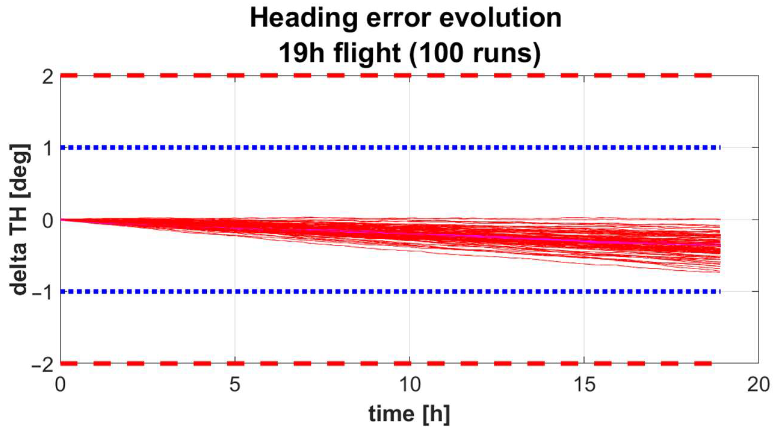
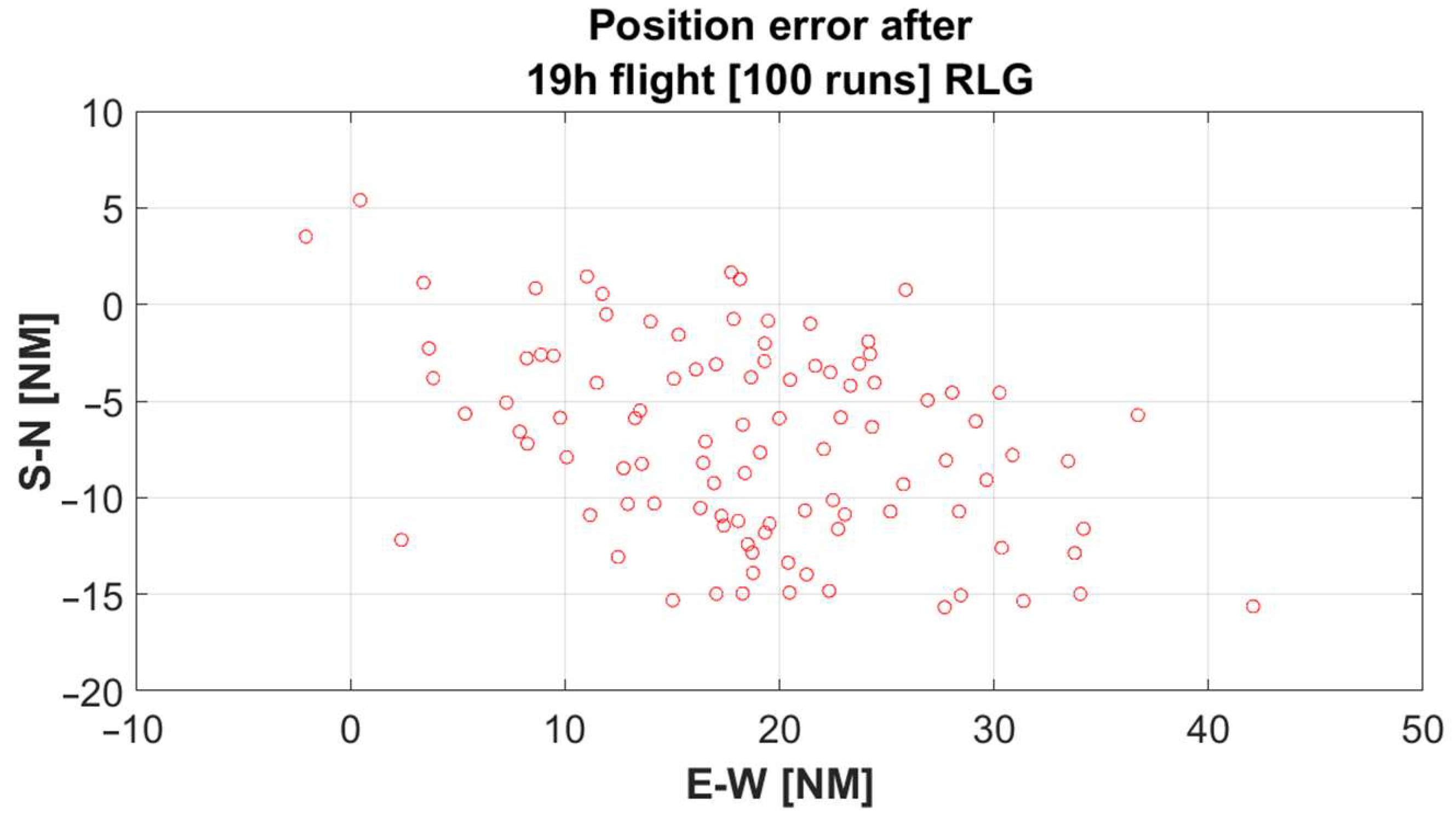
4. IRS Errors During a Long Flight

The statement that IRS cannot provide a TN reference because it is subject to un-bounded errors was also raised by the TN sceptics. The INS/IRS problem during long flights is aggravated by the fact that many modern aircraft types are capable of very long-range flights of up to 19 h of flight, in contrast with the maximum of 12 h back in the 1970s when inertial systems were introduced. In this section, we tried to put this statement to a numerical test and calculate how significant the TN directional errors can be after a 19 h long flight.
The primary source of errors in the IRS is the bias of the gyros. Because this is just a proof of concept, a simple measurement model is used for the gyros:
ω ~ t = ω t + b t * + η t
where ω is the actual value, ω ~ is the measured value, b is the bias, and η is the inevitable random noise. The bias depends on t, but much more slowly than the other quantities. We will ignore the errors introduced by the accelerometers themselves because, in the long run, the most important component of the position error is also due to the attitude error. If the current vertical is not known correctly, the positioning algorithm will integrate a small part of the acceleration of gravity.
At power up, any inertial system needs to align to the local horizontal and True North. To speed things up (the alignment can take 5 to 10 min), the system is initialised with the current latitude and longitude (although only the longitude is strictly necessary). Like anything else, this has some very small errors, but we will assume perfect initialization. Next, the IRS must propagate the attitude by integrating the gyro rates. The details of the integration depend on the internal representation of the attitude (usually quaternionic in most IRUs) and couplings are generated between all three axes. We use Euler angle representation in the simulation (it is a commercial flight with no acrobatic attitudes), and the derivatives of the angles are as follows:
ϕ ˙ = ω ^ y sin ϕ + ω ^ z cos ϕ tan θ + ω ^ x θ ˙ = ω ^ y cos ϕ ω ^ z sin ϕ ψ ˙ = ω ^ y sin ϕ + ω ^ z cos ϕ sec θ
where ω ^ is the ω ~ after subtracting Ω, the Earth’s rotation rate; and ϕ ,   θ ,   ψ are the Euler angles of bank, pitch, and yaw, respectively. Once the attitude is known, the accelerations are integrated, resulting in the speed, which is again integrated using the heading to compute the latitude and longitude. With ideal accelerometers, the only errors in position come from errors in the vertical and in the heading.
Figure 2 illustrates the results of 100 simulations: The heading error remains within reasonable values, being mostly at 0.7°, which is smaller than the expected error of the magnetic sensor. The positioning error is quite big, at around 45 NM in the worst case, and this is with ideal accelerometers. Considering the finite accuracy of the accelerometers, the error will be significantly larger for a pure inertial navigation solution.
A 19 h eastbound simulated trajectory involving some 270-degree turns at both ends was used (to simulate the departure and arrival procedures). The typical RLG performance was set for the gyro measurement equations. The results for both the position and heading errors are given in Figure 2 and Figure 3.
In a typical setup, the ADIRU is corrected with information from the GNSS and FMS. This, of course, will yield a greatly reduced value for the positioning error.
As expected, in this idealised case, there is a correlation between the heading (attitude) and positioning errors, as illustrated in Figure 4.

5. Conclusions

Among the current navigation sensors, only one is magnetic-native, five are agnostic (neutral) and can easily migrate to true, and the other five are true-native. Thus, the transition to True North can be facilitated.
By preserving the MAGVAR database, the magnetic compasses and sensors may continue to operate in the opposite way: using the database to convert to true instead of the current procedure to convert all other sensors to magnetic. Thus, the importance of frequently updating the MAGVAR database is reduced because the navigation is not compromised if the MAGVAR database is not current, as happens in Magnetic North navigation. This occurs because all other true-native sensors are disabled, and the functional redundancy principle is not respected. Only one sensor would be affected in True North navigation, leaving all others fully operational.
The INS has unbounded errors, which seems to be the main impediment to using the INS-GNSS duo as the True North navigation sensors. However, the INS unbounded errors impact the position (LAT, LONG) and not the attitude and heading angles, which remain accurate enough for the entire duration of a flight. The INS provides an accurate true HDG throughout the flight (even in the ATT mode).
The accuracy of the true HDG provided by the INS at the end of the longest flight (19 h) is at least one order of magnitude better than the accuracy of the magnetic HDG provided by the magnetometer/flux valve. This conclusion is limited by the assumptions made on the basic error equation of the gyros, and also by the limited number of trials.

Author Contributions

Conceptualization, O.T.P. and C.E.C.; methodology, O.T.P. and C.E.C.; software, C.E.C.; validation, O.T.P. and C.E.C.; writing—original draft preparation, O.T.P.; writing—review and editing, O.T.P. and C.E.C.; visualization, C.E.C.; supervision, O.T.P. All authors have read and agreed to the published version of the manuscript.

Funding

This research received no external funding.

Institutional Review Board Statement

Not Applicable.

Informed Consent Statement

Not Applicable.

Data Availability Statement

Data are contained within the article.

Conflicts of Interest

The authors declare no conflicts of interest.

References

  1. Pleter, O.T.; Constantinescu, C.E. Study on the Transition to True North in Air Navigation. Aerospace 2023, 10, 912. [Google Scholar] [CrossRef]
  2. MacKay, A.; Banning, B. Moving from Magnetic to True North in Aviation, presentation to EUROCONTROL Safety Team. 22 February 2024, unpublished. Available online: https://www.icao.int/safety/OPS/OPS-Section/Documents/ICAO%20TN%20Webinar.pdf (accessed on 13 September 2024).
  3. Pleter, O.T. Air Navigation; Springer Aerospace Technology Series; Springer: Cham, Switzerland, 2024. [Google Scholar]
  4. EASA Part-25, CS Book 1. Available online: https://www.easa.europa.eu/sites/default/files/dfu/CS-25_Amdt%203_19.09.07_Consolidated%20version.pdf (accessed on 13 September 2024).
  5. FAA TSO C6c—Direction Instrument, Magnetic (Gyroscopically Stabilized). Available online: https://drs.faa.gov/browse/excelExternalWindow/105C5F1D6A24683D862573DE005AC663.0001 (accessed on 15 September 2024).
  6. ICAO. Annex 6—Operation of Aircraft; ICAO: Montreal, QC, Canada, 2022. [Google Scholar]
  7. ICAO. Annex 10, Volume I—Radio Navigation Aids; ICAO: Montreal, QC, Canada, 2023. [Google Scholar]
  8. FAA Order 6750.24E— Instrument Landing System and Ancillary Electronic Component Configuration and Performance Requirements. Available online: https://drs.faa.gov/browse/excelExternalWindow/DRSDOCID119613350220230117182018.0001 (accessed on 15 September 2024).
  9. FAA Advisory Circular AC 120-28D. Available online: https://drs.faa.gov/browse/excelExternalWindow/BBADA17DA0D0BBD1862569BA006F64D0.0001 (accessed on 13 September 2024).
  10. EUROCONTROL Specification for Instrument Landing System (ILS). Available online: https://skybrary.aero/articles/instrument-landing-system-ils (accessed on 13 September 2024).
  11. FAA Order 9840.1—U.S. National Aviation Standard for the VOR/DME/TACAN Systems. Available online: https://www.faa.gov/regulations_policies/orders_notices/index.cfm/go/document.information/documentid/12082 (accessed on 15 September 2024).
  12. FAA Advisory Circular AC 90-94. Guidelines for using Global Positioning System Equipment for IFR En Route and Terminal Operations and for Nonprecision Instrument Approaches in the U.S. National Airspace System. Available online: https://www.faa.gov/regulations_policies/advisory_circulars/index.cfm/go/document.information/documentid/74460 (accessed on 13 September 2024).
  13. EUROCAE ED-52—MPS for conventional and Doppler VHF omnirange (C VOR and D VOR) (ground equipment). Available online: https://eshop.eurocae.net/eurocae-documents-and-reports/ed-52/# (accessed on 13 September 2024).
  14. ICAO. Annex 10, Volume IV—Surveillance Radar and Collision Avoidance Systems; ICAO: Montreal, QC, Canada, 2023. [Google Scholar]
  15. EUROCONTROL Specification for Surveillance Systems. Available online: https://www.eurocontrol.int/sites/default/files/2023-06/eurocontrol-spec-esassp-vol-1.pdf (accessed on 13 September 2024).
  16. FAA Order JO 6330.5C— Maintenance Of Airport Surface Detection Equipment (ASDE-3) Collocated With Airport Movement Area Safety System (AMASS). Available online: https://www.faa.gov/regulations_policies/orders_notices/index.cfm/go/document.information/documentID/1021392 (accessed on 13 September 2024).
  17. FAA Advisory Circular AC 20-151C Airworthiness Approval of Traffic Alert and Collision Avoidance Systems (TCAS II), Versions 7.0 & 7.1 and Associated Mode S Transponders. Available online: https://drs.faa.gov/browse/excelExternalWindow/3E508AA318155B2E86258195006EFC2C.0001 (accessed on 13 September 2024).
  18. EUROCAE ED-117—MOPS for Mode S Multilateration Systems for Use in A-SMGCS. Available online: https://eshop.eurocae.net/eurocae-documents-and-reports/ed-117a/# (accessed on 13 September 2024).
  19. IMO Resolution MSC.401(95). Available online: https://wwwcdn.imo.org/localresources/en/KnowledgeCentre/IndexofIMOResolutions/MSCResolutions/MSC.401(95).pdf (accessed on 13 September 2024).
  20. IALA Guideline 1112 on eLoran. Available online: https://www.iala.int/product/g1112/ (accessed on 13 September 2024).
  21. Federal Radionavigation Plan (FRP) 2017. Available online: https://rosap.ntl.bts.gov/view/dot/32801/dot_32801_DS1.pdf (accessed on 13 September 2024).
  22. General Lighthouse Authorities (GLA) eLoran Information. Available online: https://www.gla-rad.org/ (accessed on 13 September 2024).
  23. USCG Navigation Center—Loran-C Information. Available online: https://www.navcen.uscg.gov/loran-c-specification (accessed on 13 September 2024).
  24. FAA TSO-C4c—Inertial Navigation Systems. Available online: https://drs.faa.gov/browse/excelExternalWindow/1106C2B67A48BB7A86256DA3005D1462.0001 (accessed on 15 September 2024).
  25. FAA TSO-C5f—Airborne Attitude Heading Reference. Available online: https://drs.faa.gov/browse/excelExternalWindow/DRSDOCID136386667220231122145319.0001 (accessed on 15 September 2024).
  26. FAA AC 25-4—Inertial Navigation Systems on the certification of INS on transport category airplanes. Available online: https://www.faa.gov/regulations_policies/advisory_circulars/index.cfm/go/document.information/documentid/22459 (accessed on 13 September 2024).
  27. FAA AC 20-138D—Airworthiness Approval of Positioning and Navigation Systems. Available online: https://drs.faa.gov/browse/excelExternalWindow/87BEE4061F1C8D4086257CAF006B0C2C.0001 (accessed on 13 September 2024).
  28. EASA CS-ACNS—Certification Specifications for Airborne CNS. Available online: https://www.easa.europa.eu/en/downloads/136330/en (accessed on 13 September 2024).
  29. EASA AMC 20-4—Airworthiness Approval and Operational Criteria for the Use of Navigation Systems. Available online: https://www.easa.europa.eu/sites/default/files/dfu/Easy%20Access%20Rules%20AMC-20%20%28Amendment%204%29.pdf (accessed on 13 September 2024).
  30. FAA TSO-C145—Airborne Navigation Sensors Using The Global Positioning System Augmented By The Satellite Based Augmentation System (SBAS). Available online: https://drs.faa.gov/browse/excelExternalWindow/EFE54F1E6272A7068625811D0064B679.0001 (accessed on 15 September 2024).
  31. FAA TSO-C146—Stand-Alone and Multi-Mode GPS Receivers. Available online: https://drs.faa.gov/browse/excelExternalWindow/EFE10BFF3187F9A78625811A005E32A6.0001 (accessed on 15 September 2024).
  32. FAA AC 90-100A—U.S. Terminal and En Route Area Navigation (RNAV) Operations. Available online: https://drs.faa.gov/browse/excelExternalWindow/5C94E4F44BA319A98625729C00612F37.0001 (accessed on 13 September 2024).
  33. FAA AC 90-105A—Approval Guidance for RNP Operations. Available online: https://drs.faa.gov/browse/excelExternalWindow/DRSDOCID195761270820240724220858.0001 (accessed on 13 September 2024).
  34. EASA AMC 20-27—Airworthiness Approval and Operational Criteria for RNP RNAV Operations. Available online: https://www.easa.europa.eu/sites/default/files/dfu/agency-measures-docs-agency-decisions-2009-2009-019-R-Annex-III---AMC-20-27.pdf (accessed on 13 September 2024).
  35. ICAO. Doc 9613—Performance-Based Navigation (PBN) Manual; ICAO: Montreal, QC, Canada, 2023. [Google Scholar]
  36. Inside GNSS Magnetic Sensors in Flight Tests as Alternative PNT to GNSS, 15 June 2020. Available online: https://insidegnss.com/183615-2/ (accessed on 15 September 2024).
  37. Irani, G.B.; Christ, J.P. Image Processing for Tomahawk Scene Matching. Johns Hopkins APL Tech. Dig. 1994, 15, 250–264. [Google Scholar]
  38. Boeing. Boeing 777 Maintenance Manual Part 1—Reference 34-20-00; Boeing Corporation proprietary unpublished manual; Boeing: Washington, DC, USA.
Figure 1. Current direct indicating compass correction card (a) vs. a future TN version where the average MAGVAR in the flight area might be included in the correction card (b); for a flight to a region with a different MAGVAR, a replacement correction card could be used.
Engproc 90 00011 g001
Figure 2. True heading error for 100 runs (in red) accumulates over time, versus magnetic heading constant error margin (in blue).
Engproc 90 00011 g002
Figure 3. Position error at the end of a 19 h flight, 100 runs, RLG.
Engproc 90 00011 g003
Figure 4. True heading error as a function of positioning error at the end of a 19 h flight, 100 runs, RLG.
Engproc 90 00011 g004
Table 1. Directional sensors or methods used to calculate the heading of the aircraft HDG and the track of the flight TRK.
Directional SensorHDG ModeTRK Mode
Compass/Flux Valve/MagnetometerDirect-
Gyroscope/Laser Gyro/MEMSDirect/Integration 1-
Instrument Landing System ILS-Direct
VHF Omnidirectional Range VOR-Direct
Secondary RADAR SSR-Differentiation
LORAN/eLORAN-Differentiation
Inertial Reference System IRSDirectDirect
Global Positioning System GPS/GNSS-Differentiation
Magnetic Navigation-Differentiation
Terrain Contour MatchingDirectDifferentiation
1 Integration in case of llaser gyro and MEMS.
Table 2. Reference in use for the directional sensors or methods used to calculate direction.
Directional SensorNative Reference/Reference in UseTransition to True
Compass/Flux Valve/MagnetometerMN/MNvia MAGVAR database
Gyroscope/Laser Gyro/MEMSRemote star/Airframe 1/MNchanging correction
Instrument Landing System ILSRunway axis/MNeasy (procedural)
VHF Omnidirectional Range VORPhase of VOR signal/MNeasy (procedural)
Secondary RADAR SSRPhase of antenna/MNeasy (procedural)
LORAN/eLORANTN/TN-
Inertial Reference System IRSTN/TN-
Global Positioning System GPS/GNSSTN/TN-
Magnetic NavigationTN/TN-
Terrain Contour MatchingTN/TN-
1 Airframe for laser gyro and MEMS.
Table 3. The accuracy of the directional sensors or methods used to calculate direction.
Directional SensorRequired/Typical AccuracyNative
Datum
References
Compass/Flux Valve/Magnetometer±10°/±0.2°MN[4]
Gyroscope±2°agnostic[5,6]
Laser Gyrosee IRS--
Instrument Landing System ILS±0.5°/±0.2°agnostic[7,8,9,10]
VHF Omnidirectional Range VOR±1° target ±5°/3° localizeragnostic[7,11,12,13]
Secondary RADAR SSR±0.2°/±0.05°agnostic[14,15,16,17,18]
LORAN/eLORAN-TN[19,20,21,22,23]
Inertial Reference System IRS±0.2° align ±0.8° flight/±0.03° align 0.1° flightTN[24,25,26,27,28,29]
Global Positioning System GPS/GNSS-TN[7,27,28,30,31,32,33,34,35]
Magnetic NavigationclassifiedTN[36]
Terrain Contour MatchingclassifiedTN[37]
Disclaimer/Publisher’s Note: The statements, opinions and data contained in all publications are solely those of the individual author(s) and contributor(s) and not of MDPI and/or the editor(s). MDPI and/or the editor(s) disclaim responsibility for any injury to people or property resulting from any ideas, methods, instructions or products referred to in the content.

