Proceeding Paper

Installation Effects of Supersonic Inlets on Next-Generation SST Turbofan Engines †

Centre for Propulsion and Thermal Power Engineering, School of Aerospace, Transport and Manufacturing, Faculty of Engineering & Applied Sciences, Cranfield University, Cranfield MK43 0AL, UK
*
Author to whom correspondence should be addressed.
Presented at the 14th EASN International Conference on “Innovation in Aviation & Space towards sustainability today & tomorrow”, Thessaloniki, Greece, 8–11 October 2024.
Eng. Proc. 2025, 90(1), 50; https://doi.org/10.3390/engproc2025090050
Published: 14 March 2025

Abstract

:
This study explores inlet-related installation effects on next-generation SST aircraft, focusing on supersonic business jets. Using a comprehensive framework with consistent thrust/drag bookkeeping and realistic modeling of inlet losses, including operational limits for “buzz” and distortions, the inlet drag accounts for 8.8% to 14.2% of the installed net thrust during the supersonic segment of the mission. Variable airflow control technology is assessed, with a scheduling methodology developed to optimize the inlet operation by minimizing the installed SFC. The results show that this technology improves the installed SFC by 0.80% during supersonic cruise, enhancing the overall propulsion system performance.

1. Introduction

The forthcoming market entry of next-generation supersonic transport (SST) aircraft has prompted the International Civil Aviation Organization (ICAO) to develop standards ensuring their environmental compatibility, particularly in terms of sonic boom and Landing and Take-Off (LTO) noise [1]. On the industrial front, companies like Boom Supersonic have taken significant steps, with the “Overture” supersonic airliner representing one of the most advanced efforts toward SST sustainability [2]. Simultaneously, research activities led by organizations such as NASA, through the QueSST [3], N + 2 [4] and N + 3 [5] programs, as well as the European Union’s SENECA [6], have emerged to address challenges associated with the development of sustainable SST aircraft.
Focusing on the SENECA project, under whose umbrella this study is conducted, the central assumption is that the next-generation SST aircraft will not be permitted to fly at supersonic speeds over land due to unresolved issues with the sonic boom [6]. Consequently, the project places significant emphasis on addressing LTO noise and emission challenges. As a result, the operational profile of these aircraft is expected to include supersonic flight over water and subsonic flight over land.
The propulsion systems of next-generation SST aircraft will feature higher-bypass-ratio engines that produce lower specific thrust [7] than research activities on supersonic-capable engines of the past [8], driven by the need to meet LTO noise restrictions and higher thrust-to-weight airframe requirements [9]. However, this necessitates larger nacelles to accommodate the propulsion system, consequently introducing higher installation losses, which deteriorate the overall aircraft performance. Thus, the design of next-generation SST propulsion systems requires a compromise between the LTO exhaust velocity and minimized installation losses at supersonic speeds.
One of the most critical components of supersonic-capable propulsion systems is the inlet system, since their installation losses increase significantly when reaching supersonic speeds. Supersonic inlets’ main roles are to capture the required amount of airflow and compress and decelerate it towards the engine face at subsonic conditions, at high total pressure recovery and acceptable distortion levels, while generating minimum throttle-dependent drag forces. The supersonic flow that the inlet system captures becomes subsonic via a shock system generated by the supersonic diffuser. The flow is then further decelerated and compressed into the internal ducting that forms the subsonic diffuser. The compression generated from the inlet system contributes to the overall thermodynamic engine cycle. Furthermore, boundary-layer bleed systems are usually installed on supersonic inlets to ensure their stable operation and optimum performance by following specific scheduling per operating condition, introducing, however, additional airflow requirements and associated inlet drag.
Supersonic inlets are designed to operate in their critical mode at the design point, where a terminal normal shock is placed at the cowl lips, minimizing drag by eliminating throttle-dependent spilled flow. However, in off-design conditions, when the engine mass flow demand is lower than the inlet capacity, increased backpressure moves the terminal shock upstream, spilling excess airflow and generating additional drag, which deteriorates propulsion system performance. Consequently, significant emphasis is placed on the inlet/engine integration and exploring enabling technologies to enhance the overall propulsion system performance while meeting the environmental impact constraints.
This paper investigates the inlet-related installation losses of a propulsion system for next-generation SST aircraft, using the Cranfield University (CU) E19 Aeolus supersonic business jet as a case study [9,10]. Beyond assessing the installation losses, this study also includes the assessment of the potential of the bypass airflow control system as a technology for enhancing installed performance, demonstrating a method that schedules the bypass airflow control system to minimize the installed specific fuel consumption (SFC). While the application focuses on an M1.6 supersonic business jet, the methodological approach can also be implemented in all propulsion systems that power supersonic-capable air vehicles.

2. Methodology

2.1. Thrust/Drag Bookkeeping

A well-defined performance integration system is applied in the current research study, ensuring the consistency of the thrust/drag bookkeeping method (TBM) between the airframe and the propulsion system. The installed net thrust is defined as the uninstalled net thrust minus the sum of the inlet and afterbody installation drag forces (Equation (1)). The uninstalled net thrust is defined as the difference between the gross thrust and the ram drag while accounting for customer bleed airflow, aircraft power off-take, and inlet total pressure recovery. The inlet drag term comprises the spillage, boundary-layer bleed, and bypass drag and is defined in Equations (2) and (3). The nozzle afterbody drag term accounts for the pressure drag, the shear forces, and the shock losses. Contrary to the approach suggested by Ball and Hickcox [11], where the reference inlet and afterbody installation drag forces are assigned to the airframe, with only the throttle-dependent components of these forces considered as propulsion-system-related drag forces, this study adopts a different approach. The integrated framework, where this study takes place, precludes the availability of propulsion system component sizes that are required for the reference force evaluation, since the propulsion system size changes in the design loop. For this reason, both the reference and the throttle-dependent drag forces are bookkept within the propulsion system (Equation (4)). Consequently, to ensure comprehensive accounting of all the acting forces, both airframe and nacelle drag are reflected on the aircraft drag polar.
F n i n s t a l l e d = F n u n i n s t a l l e d ( D i n l e t + D a f t e r b o d y )
D i n l e t = D s p i l l + D b l e e d + D b y p a s s
D i n l e t = 1 2   ρ   V 2   A c   C D i n l e t
D s p i l l = D s p i l l t h o t t l e d e p e n d e n t + D s p i l l r e f e r e n c e

2.2. Integrated Framework

The present work forms part of the SENECA integrated framework, as described in more detail by Mourouzidis et al. [12], highlighting the iterative design process between the airframe and the propulsion system. The process begins with the specification and analysis of the aircraft platform, utilizing low- to medium-fidelity methods, as described by Villena et al. [9]. The mission analysis is conducted using the selected aircraft platform, generating the mission profile and thrust requirements, which are then provided to the propulsion system designers. The installed performance, size, and weight of the propulsion system are evaluated by incorporating methods and tools to ensure that the thrust requirements are met throughout the mission. The engine cycle design and uninstalled net thrust are determined using the Numerical Propulsion System Simulation (NPSS), integrated with the Performance of Installed Propulsion Systems Interactive (PIPSI) methodology, a validated tool that accurately captures installation effects by incorporating physics-based models and experimental correlations derived from inlet and exhaust system data. As detailed in Del Gatto et al. [7], the bare engine weight and size are assessed using the Cranfield University (CU) in-house tool, ATLAS, while the exhaust system weight is calculated using empirical relations. The weight of the supersonic inlet system is assessed through an updated version of the PIPSI methodology, which incorporates empirical relations tailored for the weight assessment of several types of supersonic inlet systems [13].

2.3. Supersonic Inlet Model

2.3.1. Supersonic Inlet Performance Characterization and Inlet/Engine Flow Matching

Supersonic inlets are usually equipped with auxiliary systems to enhance their operational stability, reduce distortion levels at the engine face, and improve their performance characteristics. These auxiliary systems include boundary-layer bleed features, often implemented via porous surfaces or slots, as well as bypass airflow control systems. The operation of the supersonic inlets and the associated scheduling of their auxiliary systems are closely coupled with engine performance throughout the flight mission. To achieve inlet/engine flow matching throughout the whole engine operation, this study adopts a comprehensive approach proposed in the PIPSI methodology [11]. In this approach, the inlet performance is characterized by the airflows passing through various segments of the inlet system using equivalent freestream tube areas. These areas are expressed with respect to the inlet geometric reference area, the capture area, enabling the application of standardized inlet performance maps.
The inlet system capacity per freestream Mach number is dictated by the capture area size. However, throughout the lower power off-design cases of the mission, the inlet system has excess airflow capacity, as the engine demands less airflow than the inlet capacity could provide. The excess airflow can either be spilled around the inlet or, if a bypass airflow control system is installed, bypassed.
As illustrated in Figure 1, the airflow entering the inlet system is characterized by the freestream tube area A01, while the freestream tube area A0spill represents the flow spilled around the inlet lips to match the engine mass flow requirements. This spilled flow contributes to the inlet drag, introducing a component known as spillage drag. For inlet systems equipped with boundary-layer bleed systems, an additional flow is diverted to bleed the developed boundary layer, keeping the inlet operation stable, decreasing boundary-layer shock interactions, and improving the performance characteristics. However, this bleed flow also introduces an additional inlet drag component known as boundary-layer bleed drag. The airflow passing the inlet throat corresponds to the freestream tube area A0 and determines the inlet total pressure recovery. If an inlet system is also equipped with a bypass airflow control system, additional airflow may be bypassed downstream of the inlet throat when the system is activated, introducing another inlet drag element referred to as bypass drag. As mentioned earlier, activating the bypass airflow control system is an additional option for managing the excess airflow capacity. The activation of this system reduces the inlet backpressure, causing the terminal normal shock to approach closer to the inlet lips, thereby bringing the inlet operation closer to its critical mode. The remaining airflow, corresponding to the A0eng freestream tube area, is directed to the engine face.

2.3.2. Capture Area Sizing

The inlet capture area is defined by the forward-projected area of the inlet highlight, determined by the leading edges of the supersonic diffuser [14]. This design parameter is one of the most critical ones influencing the overall inlet size and performance. The capture area is sized under the assumption that the inlet operates in its critical mode, with zero throttle-dependent spill flow and zero bypass flow. This approach minimizes the capture area, thereby optimizing the propulsion system’s performance by minimizing the installation losses associated with the inlet system at the on-design condition. This approach has been incorporated into the multi-design point methodology employed for the engine design, as detailed by Del Gatto et al. [7], in order to effectively locate the most demanding point for the capture area sizing in the design loop.

2.3.3. Operating Constraints

The inlet model incorporates operating constraints on the inlet system and consequently on the engine operation. The inlet cannot operate at an excessively high mass flow ratio, as this would result in unacceptably high distortion levels at the engine face, potentially causing the engine to stall or surge. Conversely, when operating in subcritical conditions below a certain mass flow ratio, the inlet exhibits significant flow instability, characterized by violent oscillations of the shock system—a phenomenon commonly referred to as “buzz” [15]. The PIPSI dataset includes these operational limits, enabling rapid numerical modeling using its high-fidelity data. This capability is particularly valuable in the preliminary design of the propulsion system, as accounting for such limits enhances the reliability and accuracy of the results by incorporating realistic effects of inlet and nozzle losses due to drag and internal performance.

3. Case Study

The methodology outlined in the previous section has been applied to the Cranfield University (CU) Aeolus E19 low-boom low-drag supersonic business jet, equipped with two mixed-flow turbofan engines. This work is built upon prior SENECA project studies on the airframe [9] and engine [7] design and analysis, focusing on the inlet system installation losses. The propulsion system features an underwing-mounted installation with two-dimensional, variable-ramp, external compression inlet systems, incorporating a porous bleed on ramp surfaces and a throat bleed slot (referred to as “ATS2 inlets” in Kowalski’s report [16]). The installed propulsion system performance has been evaluated both with and without an overboard variable bypass airflow control system, i.e., bypass doors and slotted plates. This assessment aims to determine the effectiveness of such technology in supersonic transport aircraft propulsion systems by quantifying the associated performance benefits.

4. Results

The design point of the inlet capture area, regardless of whether a variable bypass airflow control system is installed, corresponds to the supersonic top of climb (STOC) that coincides with the beginning of supersonic cruise. This is consistent with NASA’s N + 2 studies [4]. The bypass airflow control system does not affect the sizing of the capture area, as per the guidelines outlined in Section 2.3.2, where the bypass is assumed to be closed and the inlet operation in its critical mode.
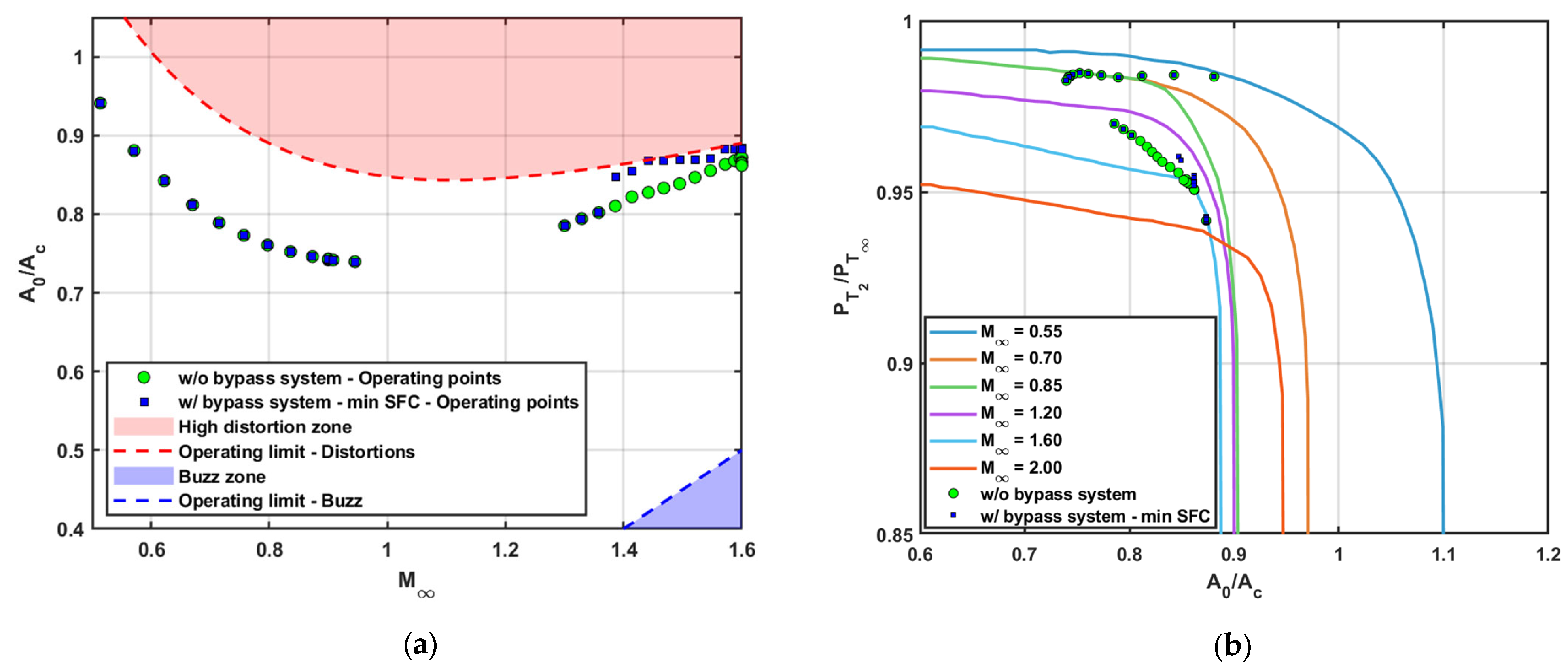
When the inlet system is not equipped with a bypass airflow control system, it operates subcritically under all reduced power off-design conditions, as illustrated in Figure 2a,b, spilling the excess airflow around the inlet lips to match the engine requirements. In contrast, a variable bypass airflow control system allows the regulation of the inlet backpressure by bypassing the excess airflow downstream the inlet throat, shifting the inlet operation towards its critical mode, affecting the resulting inlet total pressure and the boundary-layer bleed requirements. At the same time, the bypass airflow control system also regulates the spillage and bypass drag by managing the excess airflow. Consequently, bypassing excess airflow affects the inlet operating conditions and thereby all the inlet performance parameters.
The scheduling of the bypass airflow control system depends on the operational objective of the propulsion system operation. For supersonic civil transport applications, where fuel efficiency emerges as a pivotal parameter, directly influencing the aircraft’s market viability and operational costs, the system is scheduled to minimize the installed SFC by trading between the overall inlet drag and total pressure recovery.
Figure 3a presents a typical off-design supersonic cruise point, breaking down the overall inlet drag into its spillage, bleed, and bypass components. Increasing the bypass airflow to match the engine requirements reduces the spillage drag by limiting the amount of airflow that is spilled around the inlet while simultaneously increasing the bypass drag. At the same time, as bypass airflow increases, the inlet approaches its critical operating mode, reducing the boundary-layer bleed requirements and consequently the bleed drag. For the illustrated case, the overall inlet drag demonstrates a decreasing trend as the bypass airflow increases.
Figure 3b illustrates the trade-off between the overall inlet drag (scaled by a factor of 10 for clarity) and the total pressure recovery at the previously mentioned off-design point. The concurrent decrease in overall inlet drag and total pressure recovery has opposing effects on the installed SFC. The installed SFC is minimized at a specific setting of the bypass airflow control system, where the excess airflow is partially spilled, and the remainder is bypassed overboard.
This scheduling strategy is applied throughout the entire mission profile, with the results displayed in Figure 2. As shown, the activation of the bypass airflow control system is efficient only during the supersonic climb and cruise phases. For the remainder of the mission, achieving inlet/engine matching by spilling the excess airflow yields improved performance, without reaching the buzz limit. As illustrated in Figure 2a and previously discussed, the activation of the bypass airflow control system allows the inlet to operate at higher mass flow ratios compared to an inlet that does not have overboard bypassing capabilities. The effect of increasing the operating mass flow ratio on the total pressure recovery is depicted in Figure 2b, which also demonstrates the shift of the inlet operation towards its critical point when the bypass airflow control system is activated.
It is noted that in Figure 2a,b, the transonic acceleration zone is characterized by its starting and ending points to effectively capture the installation effects of the supersonic inlet and the influence of the bypass airflow control system in this segment. Midpoints within the transonic acceleration phase are excluded, as accurately representing transonic aerodynamics at these points requires higher-fidelity methods.
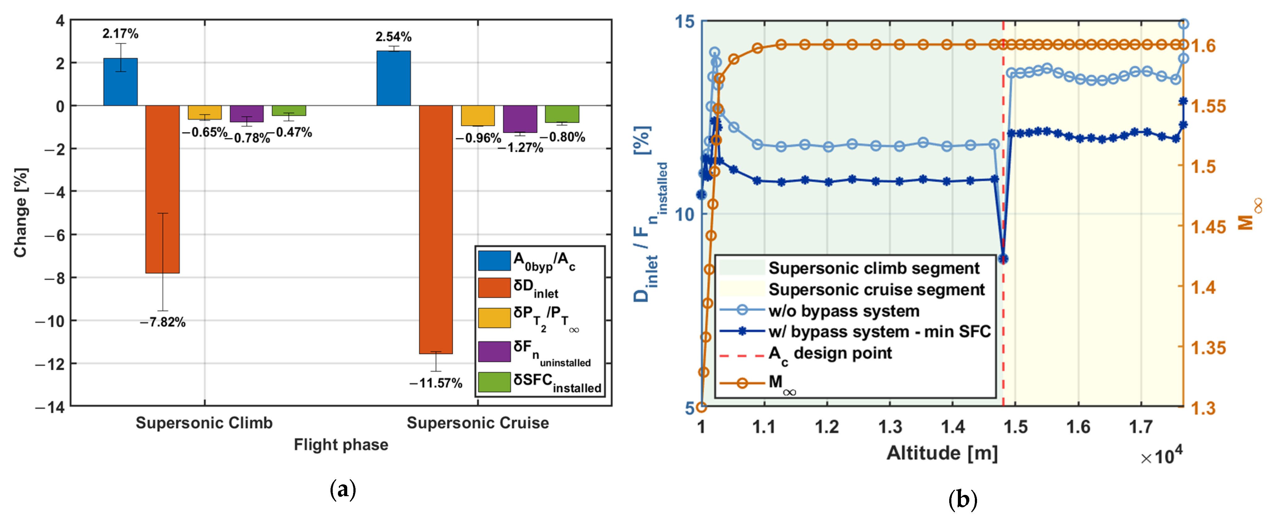
The overall impact of the variable bypass airflow control system technology on propulsion system performance is illustrated in Figure 4a. For the supersonic climb segment, setting the bypass mass flow ratio to 2.17% reduces the overall inlet drag forces by 7.82% and total pressure recovery by 0.65% compared with an inlet system without variable bypass airflow control technology. This results in a reduction in the uninstalled net thrust requirements by 0.78%, improving the installed SFC by 0.47%. In the supersonic cruise segment, a bypass mass flow ratio of 2.54% reduces the overall inlet drag forces by 11.57%, accompanied by a reduction in total pressure recovery by 0.96%. These changes lead to a 1.27% reduction in uninstalled net thrust requirements, resulting in a 0.80% improvement in the installed SFC. The afterbody drag percentage changes are not included in the bar charts, as their contribution is negligible.
Figure 4b illustrates that for next-generation supersonic business jets, when a bypass airflow control system is not installed on the inlet, the inlet drag accounts for 10.5% to 14.2% of the installed net thrust during supersonic climb and approximately 13.6% during supersonic cruise, significantly affecting the installed propulsion system performance. When the bypass airflow control system is installed and scheduled to minimize the installed SFC, the inlet drag is reduced within the range of 10.5% to 12.4% of the installed net thrust during supersonic climb and by approximately 12.1% during supersonic cruise. The kink in the diagram in Figure 4b represents the supersonic top of climb, where the inlet capture area is sized, and consequently the throttle-dependent spillage and bypass drag are zero, minimizing the overall inlet drag, which accounts for 8.8% of the installed net thrust.

5. Conclusions

This study examines and quantifies the inlet installation losses of a next-generation SST propulsion system, case-studying the CU Aeolus E19 aircraft. By implementing the inlet performance maps from the PIPSI dataset, the analysis captures realistic inlet effects and associated throttle dependencies while incorporating operational constraints to avoid the “buzz” and unacceptable distortion levels at the engine face.
The findings reveal that inlet installation drag significantly deteriorates the overall propulsion system performance, accounting for 10.5% to 14.2% of the installed net thrust during supersonic climb and approximately 13.6% during supersonic cruise.
Furthermore, the bypass airflow control technology has been assessed, and a scheduling methodology has been developed to minimize the installed SFC by trading between the spillage, bleed, bypass drag, and total pressure recovery. This technology has proved to be beneficial, since it reduced the overall inlet drag by 7.82% during supersonic climb and 11.57% during supersonic cruise, with a corresponding 0.65% and 0.96% total pressure recovery drop, respectively. Overall, the additional degree of freedom that is introduced by the variability of the bypass airflow control system enabled an installed SFC improvement of 0.47% during supersonic climb and 0.80% during supersonic cruise.
This methodology and its results demonstrate that adopting integrated design approaches—incorporating potential system variabilities, such as a bypass airflow control system—can lead to more advanced designs with enhanced overall aircraft performance, thereby contributing to reduced operating costs and greater market viability for next-generation SST aircraft.

Author Contributions

Conceptualization, S.A. and D.D.G.; methodology, S.A., D.D.G., S.B., C.M. and V.P.; analysis, S.A., D.D.G., S.B. and C.M.; writing—original draft preparation, S.A.; writing—review and editing, S.B., S.A., C.M. and V.P.; supervision, S.B., C.M. and V.P.; project administration, S.B., C.M. and V.P. All authors have read and agreed to the published version of the manuscript.

Funding

This research was funded by the SENECA project under the European Union’s Horizon 2020 research and innovation program, grant agreement No. 101006742.

Institutional Review Board Statement

Not applicable.

Informed Consent Statement

Not applicable.

Data Availability Statement

Data are contained within the article.

Conflicts of Interest

The author declares no conflicts of interest.

Nomenclature

A c Inlet capture area
A 01 Equivalent freestream tube area of the inlet airflow demand including the boundary-layer bleed requirements
A 0 Equivalent freestream tube area of the inlet airflow demand passing through the inlet throat
A 0 e n g Equivalent freestream tube area of the engine airflow demand
A 0 s p i l l Equivalent freestream tube area of the spilled airflow
A 0 b l d Equivalent freestream tube area of the boundary-layer bleed airflow
A 0 b y p Equivalent freestream tube area of the bypassed airflow
C D i n l e t Total inlet drag coefficient normalized on the capture area
C D s p i l l Spillage drag coefficient normalized on the capture area
C D b l e e d Bleed drag coefficient normalized on the capture area
C D b y p a s s Bypass drag coefficient normalized on the capture area
D i n l e t Total inlet drag force
D a f t e r b o d y Total afterbody drag force
F n u n i n s t a l l e d Uninstalled net thrust force
F n i n s t a l l e d Installed net thrust force
M Freestream Mach number
P t 2 / P t Inlet total pressure recovery
S F C i n s t a l l e d Installed specific fuel consumption
V Freestream velocity
ρ Freestream air density

References

  1. International Civil Aviation Organization. Available online: https://www.icao.int/environmental-protection/pages/Supersonic-Aircraft-Noise-Standards-Development.aspx (accessed on 25 November 2024).
  2. Boom Supersonic. Available online: https://boomsupersonic.com/overture (accessed on 25 November 2024).
  3. NASA. Available online: https://www.nasa.gov/mission/quesst/ (accessed on 25 November 2024).
  4. Wedge, H.R.; Bonet, J.; Magee, T.; Chen, D.; Hollowell, S.; Kutzmann, A.; Mortlock, A.; Stengle, J.; Nelson, C.; Adamson, E.; et al. N+2 Supersonic Concept Development and Systems Integration. NASA/CR–2010-216842. 1 August 2010. Available online: https://ntrs.nasa.gov/api/citations/20100030607/downloads/20100030607.pdf (accessed on 25 November 2024).
  5. Welge, H.R.; Bonet, J.; Magee, T.; Tompkins, D.; Britt, T.R.; Nelson, C.; Miller, G.; Stenson, D.; Staubach, J.B.; Bala, N.; et al. N+3 Advanced Concept Studies for Supersonic Commercial Transport Aircraft Entering Service in the 2030–2035 Period. NASA/CR–2011-217084. 1 April 2011. Available online: https://ntrs.nasa.gov/api/citations/20110010973/downloads/20110010973.pdf (accessed on 25 November 2024).
  6. SENECA Project. Available online: https://seneca-project.eu/ (accessed on 25 November 2024).
  7. Del Gatto, D.; Adamidis, S.; Mourouzidis, C.; Brown, S.; Pachidis, V. Design space exploration of next-generation supersonic business jet engine with a focus on Landing and Take-Off (LTO) noise. In Proceedings of the ICAS 2024, Stresa, Italy, 8–12 September 2024; International Council of the Aeronautical Sciences: Florence, Italy, 2024. [Google Scholar]
  8. Berton, J.; Haller, W. A Comparative Propulsion System Analysis for the High-Speed Civil Transport. NASA/TM-2005-213414. 1 February 2005. Available online: https://ntrs.nasa.gov/api/citations/20050123580/downloads/20050123580.pdf (accessed on 25 November 2024).
  9. Villena, M.C.; Lawson, C.; Riaz, A.; Jaron, R. Conceptual Design of Supersonic Aircraft to Investigate Environmental Impact. In Proceedings of the AIAA SciTech 2024 Forum, Orlando, FL, USA, 8–12 January 2024. [Google Scholar]
  10. Smith, H.; Sun, Y. Design case of the E-19 AEOLUS supersonic business jet. In Proceedings of the AIAA Aviation 2020 Forum, Virtual event, 15–19 June 2020. [Google Scholar]
  11. Ball, W.H.; Hickcox, T.E. Rapid Evaluation of Propulsion System Effects—Volume 2; AFFDL-TR-78-91; Air Force Flight Dynamics Laboratory: Montgomery, OH, USA, 1978. [Google Scholar]
  12. Mourouzidis, C.; Del Gatto, D.; Adamidis, S.; Munoz, C.V.; Lawson, C.; Corzo, B.M.; Leyland, P.; Marsh, D.; Lim, L.; Owen, B.; et al. Preliminary Design of Next Generation Mach 1.6 Supersonic Business Jets to Investigate Landing & Take-Off (LTO) Noise and Emissions—SENECA. J. Phys. Conf. Ser. 2023, 2526, 012011. [Google Scholar]
  13. Kowalski, E.J. Computer Code for Estimating Installed Performance of Aircraft Gas Turbine Engines—Volume 1. NASA/CR-159691. 1 December 1979. Available online: https://ntrs.nasa.gov/citations/19800004788 (accessed on 25 November 2024).
  14. Slater, J.W. SUPIN: A Computational Tool for Supersonic Inlet Design. AIAA 2016-0530. In Proceedings of the 54th AIAA Aerospace Sciences Meeting, San Diego, CA, USA, 4–8 January 2016. [Google Scholar]
  15. Chima, R.V. Analysis of Buzz in a Supersonic Inlet. NASA/TM–2012-217612. 1 May 2012. Available online: https://ntrs.nasa.gov/api/citations/20120009203/downloads/20120009203.pdf (accessed on 25 November 2024).
  16. Kowalski, E.J.; Atkins, R., Jr. Computer Code for Estimating Installed Performance of Aircraft Gas Turbine Engines—Volume 3. NASA/CR-159693. 1 December 1979. Available online: https://ntrs.nasa.gov/citations/19800004790 (accessed on 25 November 2024).
Figure 1. Representation of the freestream tube areas that characterize the flows passing through several segments of the inlet system.
Engproc 90 00050 g001
Figure 2. Inlet performance characteristics across the mission profile with (w/) and without (w/o) the bypass airflow control system. (a) Matched mass flow versus flight Mach number. (b) Total pressure recovery as a function of matched mass flow ratios.
Engproc 90 00050 g002
Figure 3. (a) Breakdown of the overall inlet drag coefficient into spillage, boundary-layer bleed, and bypass drag coefficient as a function of the bypass mass flow ratio. (b) Optimal scheduling of the bypass airflow control system to minimize the installed SFC, demonstrating the trade-off between inlet drag and total pressure recovery. The optimal bypass setting is highlighted with a red arrow.
Engproc 90 00050 g003
Figure 4. Effect of the bypass airflow control system on propulsion performance. (a) Main performance differences between inlet systems with and without bypass airflow control. (b) Comparison of inlet drag-to-installed net thrust ratio between inlet systems with and without bypass airflow control, during supersonic climb and cruise.
Engproc 90 00050 g004
Disclaimer/Publisher’s Note: The statements, opinions and data contained in all publications are solely those of the individual author(s) and contributor(s) and not of MDPI and/or the editor(s). MDPI and/or the editor(s) disclaim responsibility for any injury to people or property resulting from any ideas, methods, instructions or products referred to in the content.