Flexural and Shear Strengthening of Reinforced-Concrete Beams with Ultra-High-Performance Concrete (UHPC)


Abstract
:1. Introduction
2. Effect on Flexural Strength
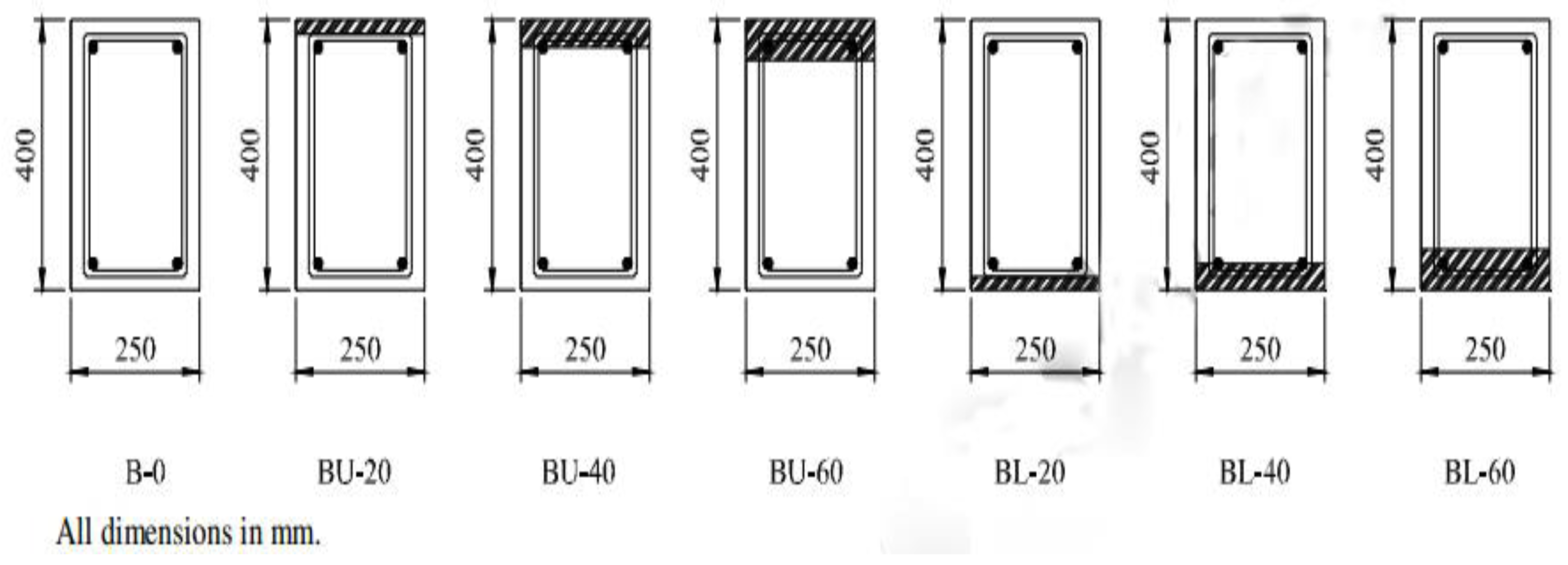
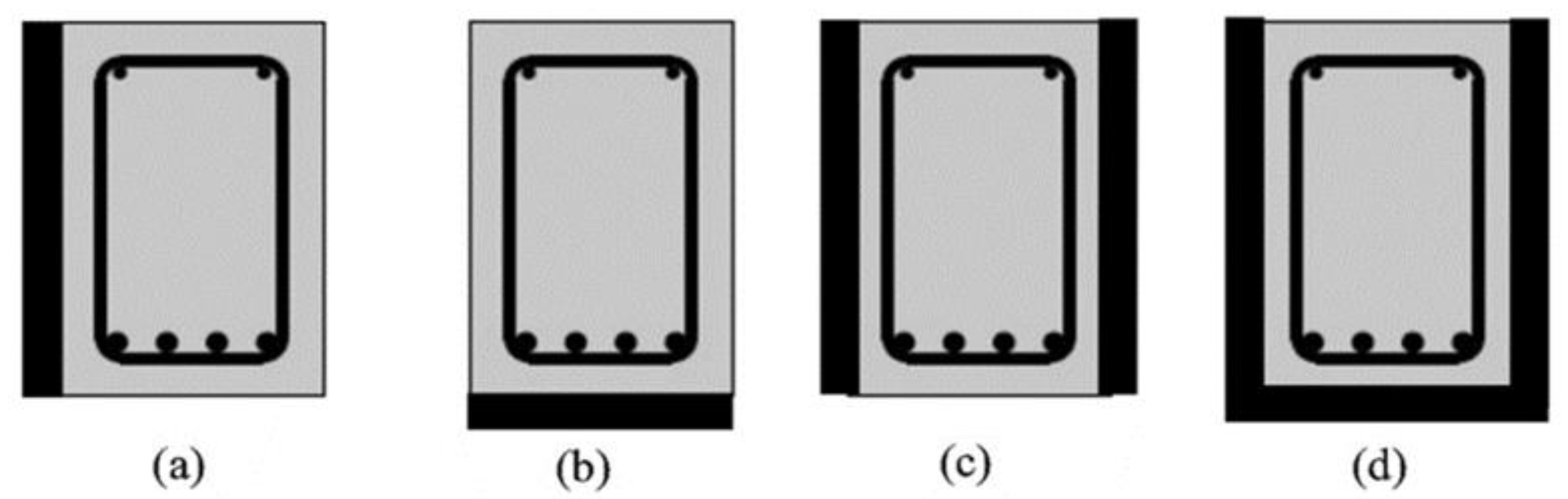
2.1. Effect of UHPC Layer Position
2.2. Effect of Beam Depth and UHPC Layer Thickness Ratio
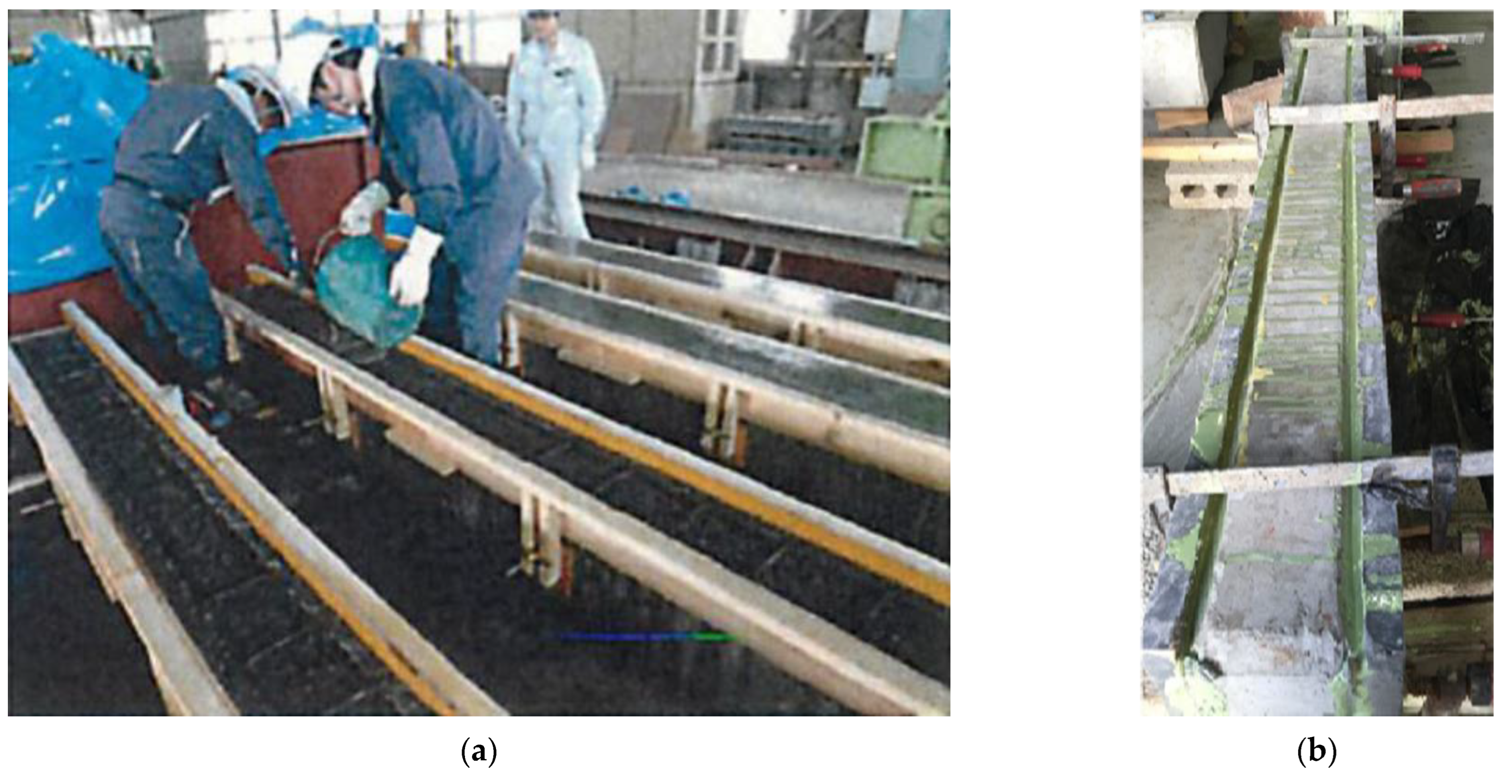
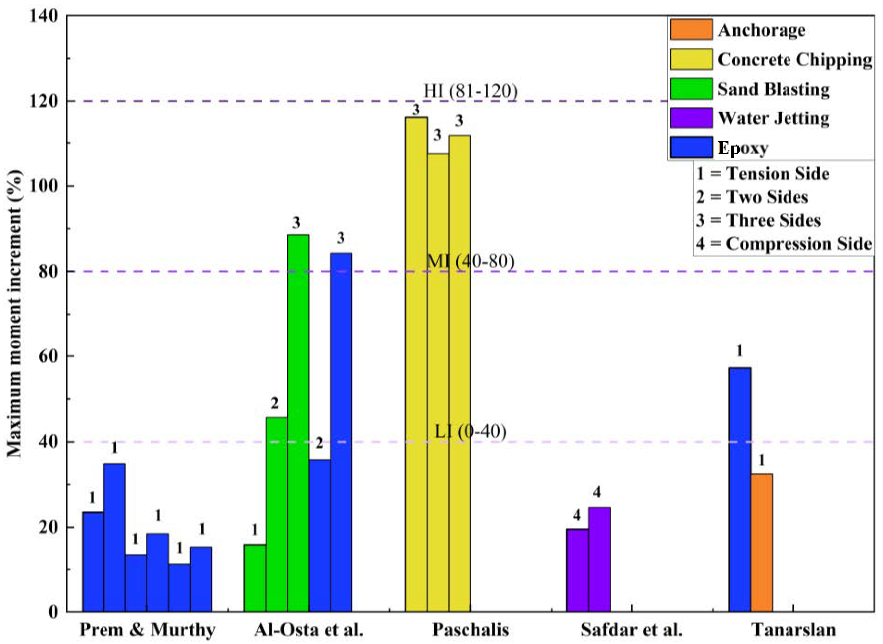
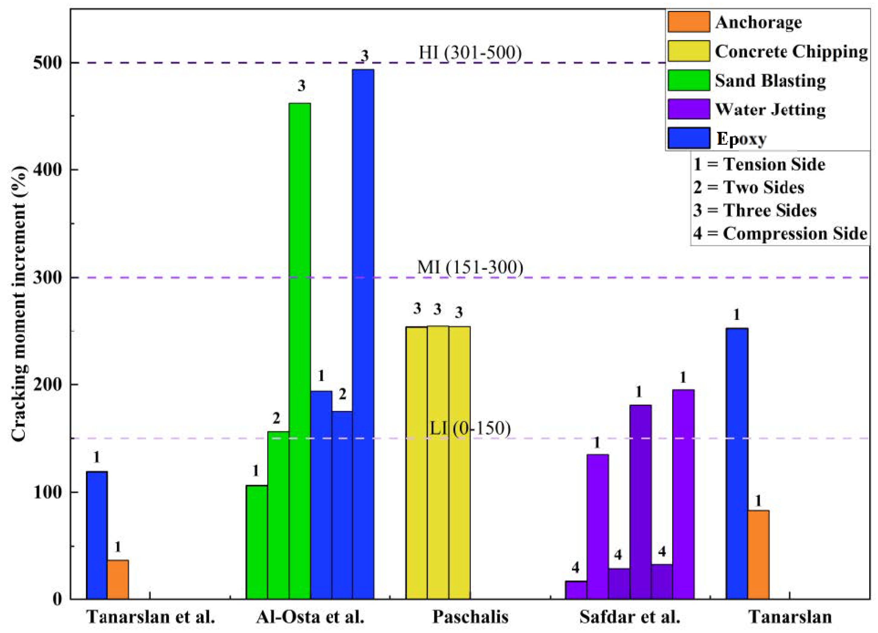
2.3. Effect of Bonding Techniques
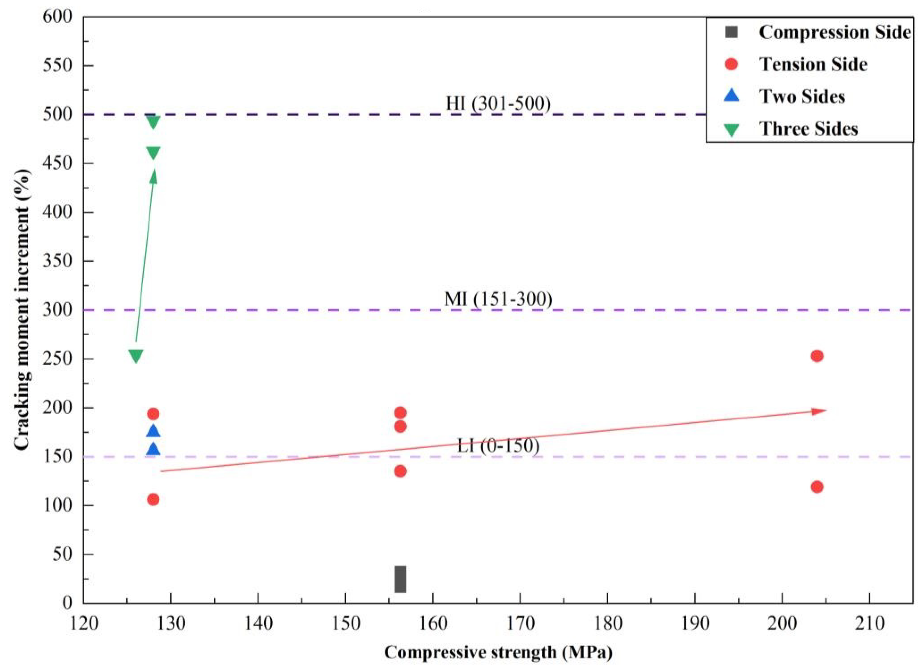
2.4. Effect of Compressive Strength
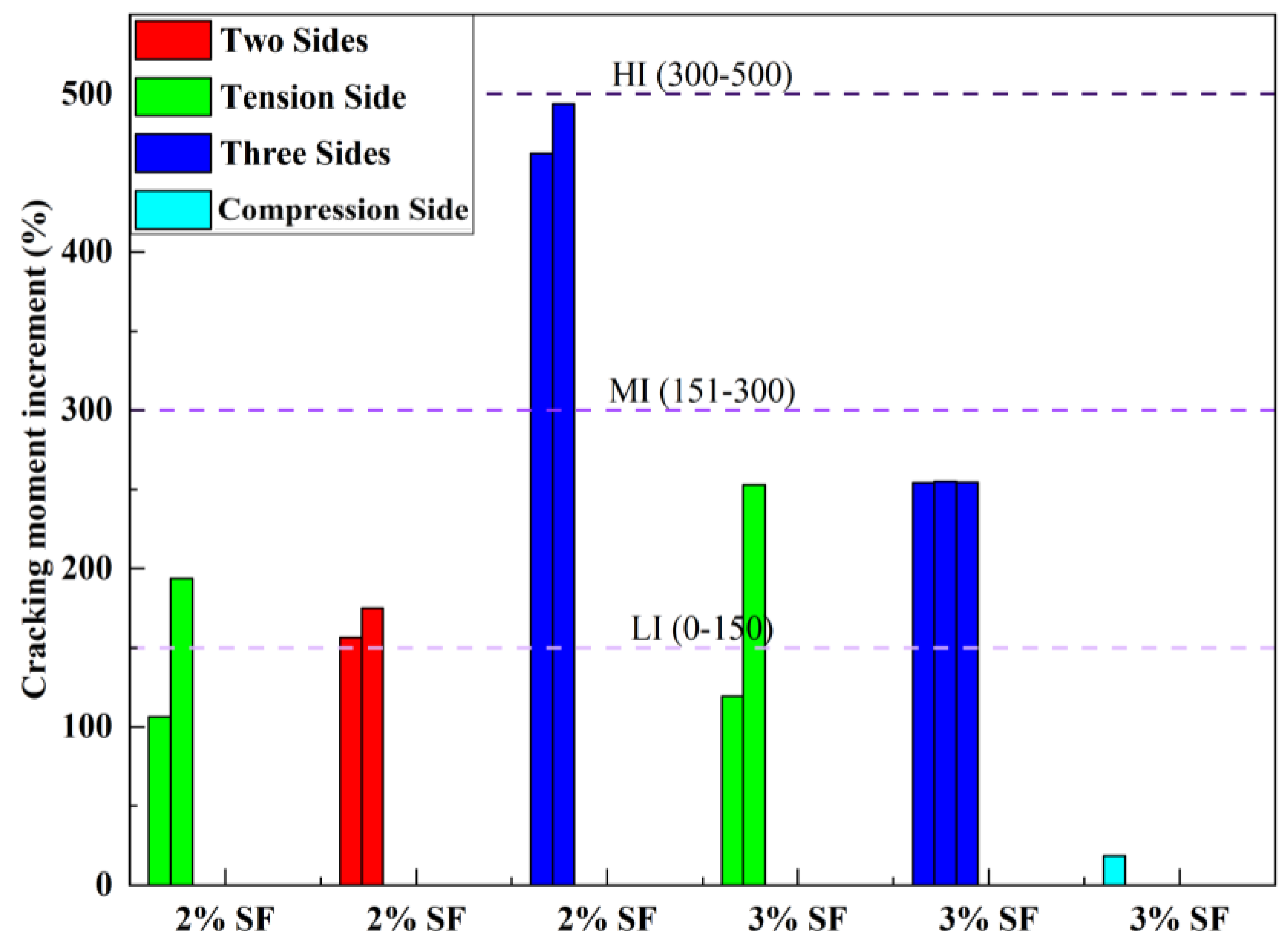
2.5. Effect of Steel Fiber Percentage
3. Effect on Shear Strength
3.1. Effect of UHPC Layer Position
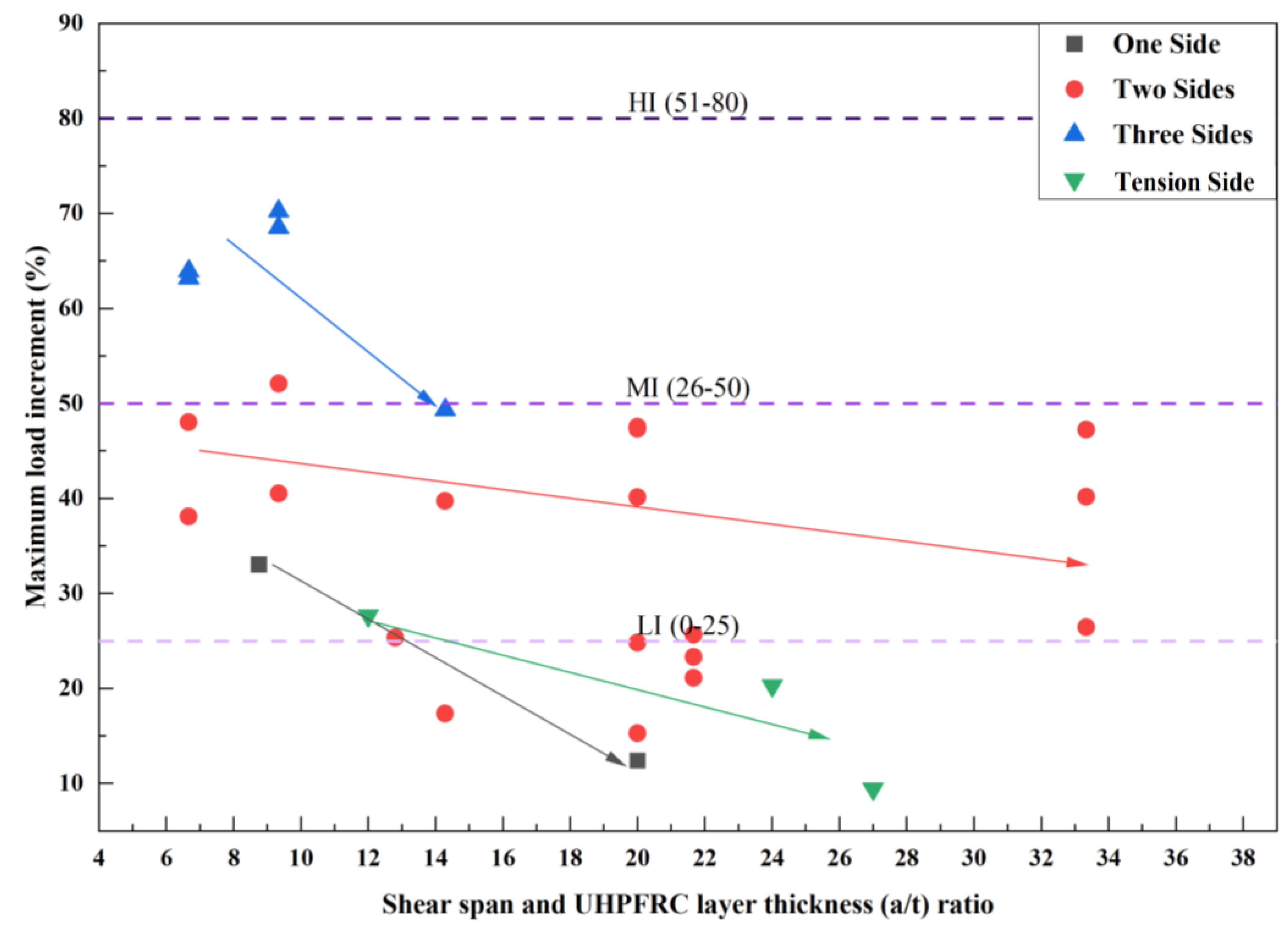
3.2. Effect of Shear Span and UHPC Layer Thickness Ratio
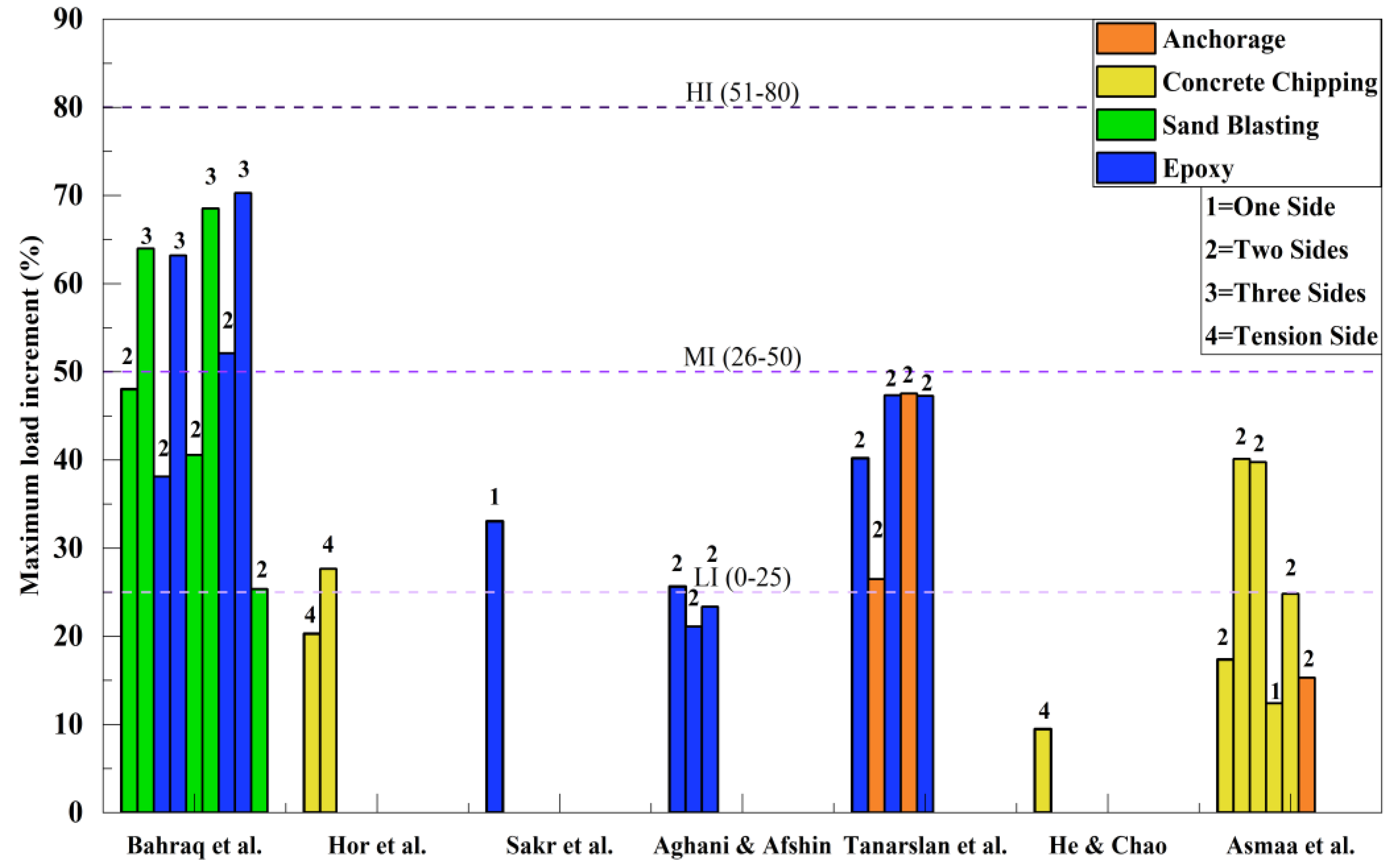
3.3. Effect of Bonding Techniques
3.4. Effect of UHPC Compressive Strength
3.5. Effect of Steel Fiber Percentage
4. Conclusions
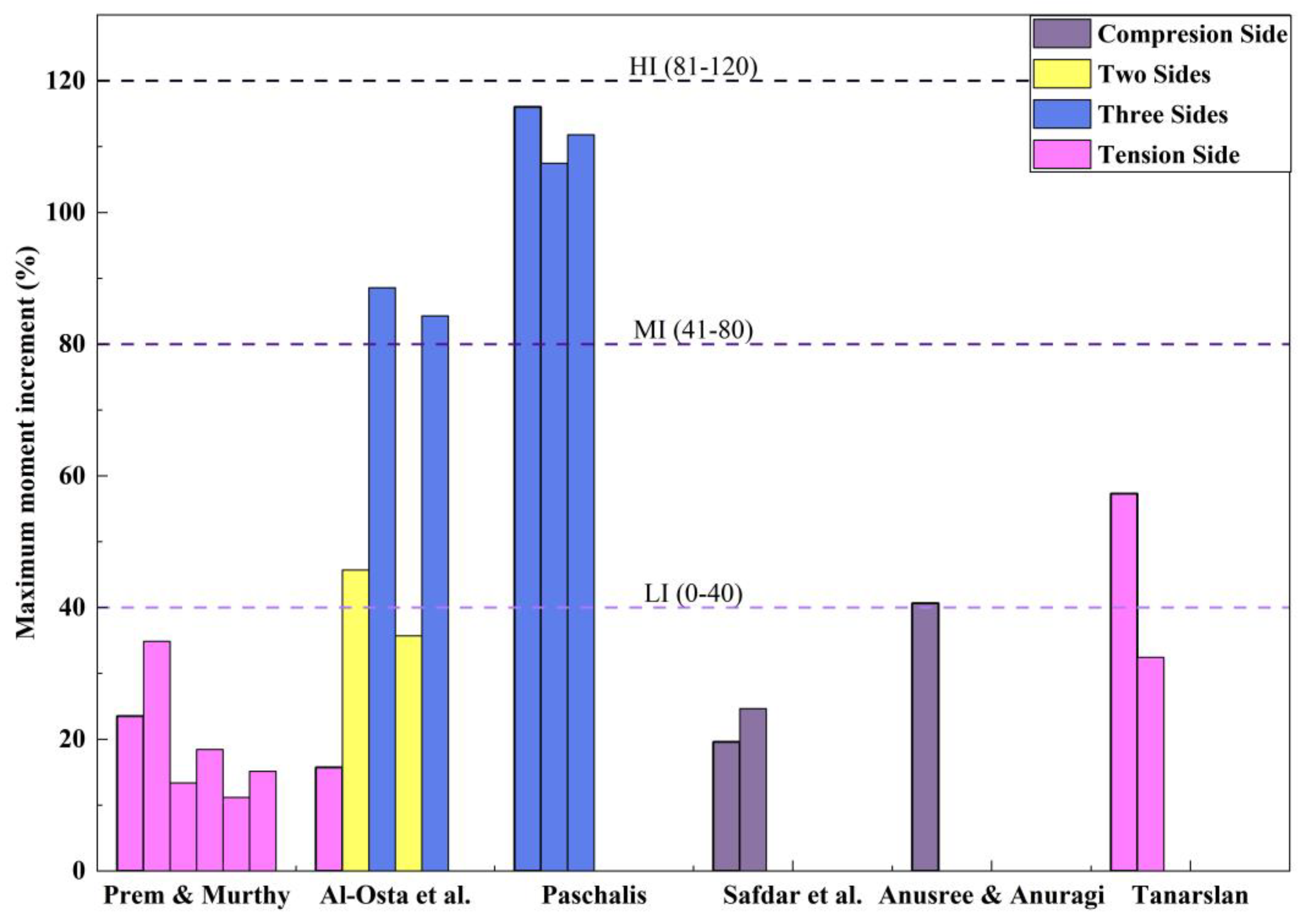
- RC beams strengthened on three sides demonstrated a better performance in terms of the cracking moment and maximum moment (falls in the high increment range). Nevertheless, the percentage of the cracking moment increment was higher than the percentage of the maximum moment. This behavior can be attributed to the presence of fiber, which resulted in delayed crack opening due to the bridging effect between fiber and concrete.
- For flexural strengthening, the composite structure exhibited mostly monolithic behavior under mechanical loading, exhibiting a negligible slip at the interface and no debonding.
- Experimental studies on the shear strengthening of RC beams demonstrated that the three-side strengthening arrangement provided the best results in terms of load-carrying capacity (falls in the high increment range).
- As the shear span and strengthening layer thickness ratio increased, the percentage of the load increment decreased after a specific range.
- The shear span, strengthening configurations, and strengthening layer thickness ratios have a remarkable effect on altering the failure mode in the case of shear strengthening.
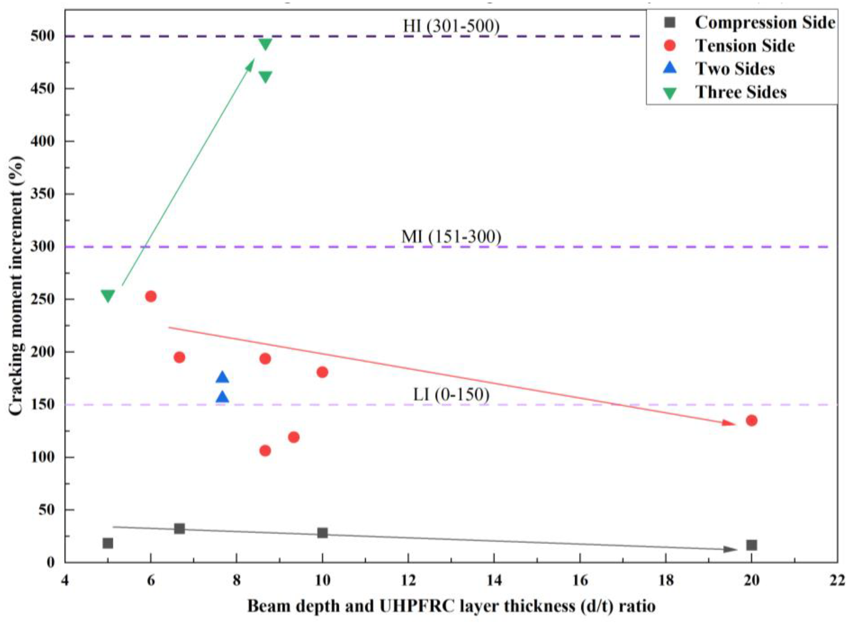
- Effective depth and strengthening layer thickness ratios have shown a nonlinear effect on the percentage of the moment increment (cracking and maximum) in different strengthening configurations.
- In summary, the investigation results revealed that the three-side strengthening exhibits a notably higher range of the increment for both flexural (maximum at 81–120% and cracking at 300–500%) and shear (maximum at 51–80% and cracking at 121–180%) strengthening when compared to other strengthening configurations, encompassing all other parameters.
- In the case of flexural strengthening, UHPC and concrete substrates sometimes behave separately due to (1) localized macro-cracks between the old concrete structure and UHPC layer; and (2) an improper distribution of steel fiber in UHPC casting. These factors need to be considered in future studies.
- Most of the studies in the literature focused on strengthening (flexural and shear) of the RC beams in uncracked conditions, which does not represent the actual behavior of the damaged structure. So, future studies should consider strengthening the damaged RC beams.
- Flexural and shear strengthening of corroded RC beams with different configurations of UHPC layers needs to be investigated.
- The past studies mainly focused on static loading, with a few explorations into cyclic loading. So, further investigation is required to understand the response to cyclic loading, including factors like fatigue and seismic loading.
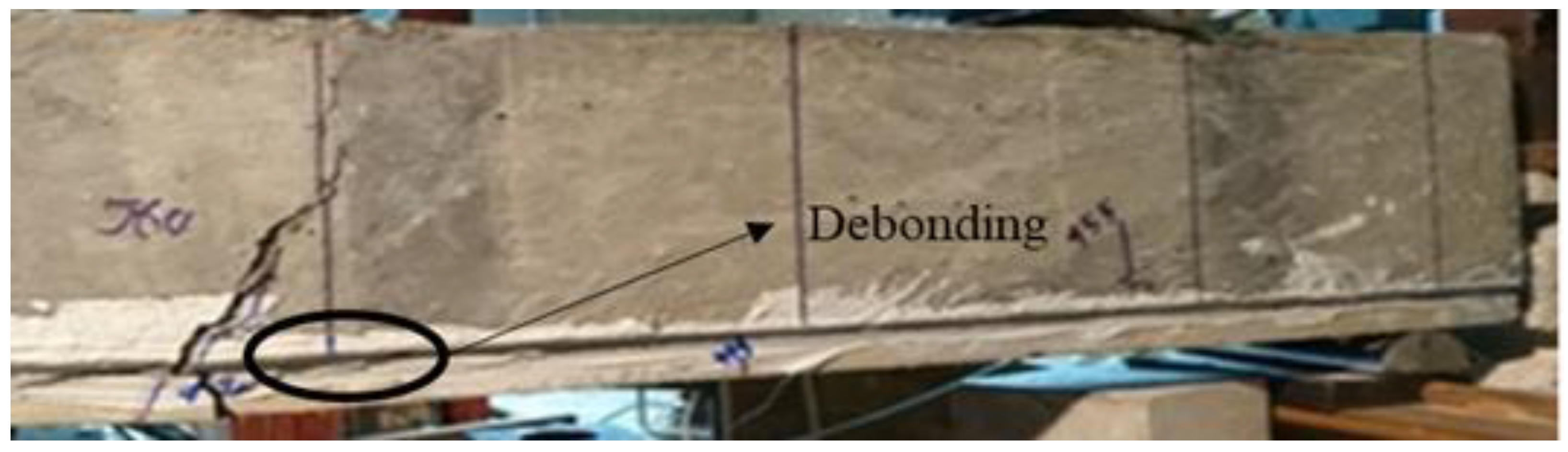
- For cast-in situ applications, tensile stresses are generated due to the high shrinkage of UHPC, which creates a threat of a debonding/slip at the surface between concrete and UHPC layers. Thus, a proper guideline needs to be developed in cases of water jetting and concrete chipping.
Author Contributions
Funding
Data Availability Statement
Conflicts of Interest
References
- Alaee, F.J.; Karihaloo, B.L. Retrofitting of Reinforced Concrete Beams with CARDIFRC. J. Compos. Constr. 2003, 7, 174–186. [Google Scholar] [CrossRef]
- Lee, M.G.; Wang, Y.C.; Chiu, C.T. A Preliminary Study of Reactive Powder Concrete as a New Repair Material. Constr. Build. Mater. 2007, 21, 182–189. [Google Scholar] [CrossRef]
- Biswas, R.K.; Iwanami, M.; Chijiwa, N.; Uno, K. Effect of Non-Uniform Rebar Corrosion on Structural Performance of RC Structures: A Numerical and Experimental Investigation. Constr. Build. Mater. 2020, 230, 116908. [Google Scholar] [CrossRef]
- Biswas, R.K.; Iwanami, M.; Chijiwa, N.; Uno, K. Finite Element Analysis of RC Beams Subjected to Non-Uniform Corrosion of Steel Bars. In Proceedings of the 5th International Conference on Sustainable Construction Materials and Technologies (SCMT5), London, UK, 15–17 July 2019. [Google Scholar]
- Biswas, R.K.; Iwanami, M.; Chijiwa, N.; Nakayama, K. Numerical Evaluation on the Effect of Steel Bar Corrosion on the Cyclic Behaviour of RC Bridge Piers. Mater. Today Proc. 2021, 44, 2393–2398. [Google Scholar] [CrossRef]
- Biswas, R.K.; Iwanami, M.; Chijiwa, N.; Nakayama, K. Structural Assessment of the Coupled Inf luence of Corrosion Damage and Seismic Force on the Cyclic Behaviour of RC Columns. Constr. Build. Mater. 2021, 304, 124706. [Google Scholar] [CrossRef]
- Biswas, R.K.; Iwanami, M.; Chijiwa, N.; Saito, T.; Malaga-Chuquitaype, C. A Simplified Approach to Evaluate Cyclic Response and Seismic Fragility of Corrosion Damaged RC Bridge Piers. Dev. Built Environ. 2022, 12, 100083. [Google Scholar] [CrossRef]
- Datta, D. Electrospun Recycled Polyethylene Terephthalate Microfibers as an Asphalt Mix Additive. Master’s Thesis, South Dakota State University, Brookings, SD, USA, 2023. [Google Scholar]
- Biswas, R.K.; Iwanami, M.; Chijiwa, N.; Saito, T. The Effect of Non-Uniform Steel Bar Corrosion on Pre-Stressed RC Members Subjected to Hysteretic Load at the Mid-Span: Experimental Study and Three-Dimensional FEM Modeling. Arch. Civ. Mech. Eng. 2023, 23, 163. [Google Scholar] [CrossRef]
- El Kechebour, B.; Zeloum, H. Choice between Retrofitting and Reconstruction of Buildings in Reinforced Concrete after an Earthquake. Adv. Mater. Res. 2015, 1119, 736–740. [Google Scholar] [CrossRef]
- Brühwiler, E. Rehabilitation of Concrete Bridges Using Ultra-High Fibre Reinforced Concrete (UHPFRC). In Proceedings of the 3rd International Symposium on Life-Cycle Civil Engineering, Vienna, Austria, 3–6 October 2012; Strauss, A., Frangopol, D.K., Eds.; CRC Press: Vienna, Austria, 2012; pp. 1934–1941. [Google Scholar]
- Jose, J.; Nagarajan, P.; Remanan, M. Utilisation of Ultra-High Performance Fiber Reinforced Concrete(UHPFRC) for Retroffiting—A Review. In Proceedings of the International Conference on Materials, Mechanics and Structures 2020 (ICMMS2020); IOP Conf. Series: Materials Science and Engineering, Online, 14–15 July 2020; Volume 936, pp. 1–8. [Google Scholar]
- Oehlers, D.J. Reinforced Concrete Beams with Plates Glued to Their Soffits. J. Struct. Eng. 1992, 118, 2023–2038. [Google Scholar] [CrossRef]
- Souza, R.H.F.; Appleton, J. Flexural Behaviour of Strengthened Reinforced Concrete Beams. Mater. Struct. 1997, 30, 154–159. [Google Scholar] [CrossRef]
- Yurdakul, Ö.; Avşar, Ö. Strengthening of Substandard Reinforced Concrete Beam-Column Joints by External Post-Tension Rods. Eng. Struct. 2016, 107, 9–22. [Google Scholar] [CrossRef]
- Altun, F. An Experimental Study of the Jacketed Reinforced-Concrete Beams under Bending. Constr. Build. Mater. 2004, 18, 611–618. [Google Scholar] [CrossRef]
- Alhadid, M.M.A.; Youssef, M.A. Analysis of Reinforced Concrete Beams Strengthened Using Concrete Jackets. Eng. Struct. 2017, 132, 172–187. [Google Scholar] [CrossRef]
- Tetta, Z.C.; Koutas, L.N.; Bournas, D.A. Textile-Reinforced Mortar (TRM) versus Fiber-Reinforced Polymers (FRP) in Shear Strengthening of Concrete Beams. Compos. Part B Eng. 2015, 77, 338–348. [Google Scholar] [CrossRef]
- Spadea, G.; Bencardino, F.; Swamy, R.N. Structural Behavior of Composite RC Beams with Externally Bonded CFRP. J. Compos. Constr. 1998, 2, 132–137. [Google Scholar] [CrossRef]
- Lamanna, A.J.; Bank, L.C.; Scott, D.W. Flexural Strengthening of Reinforced Concrete Beams by Mechanically Attaching Fiber-Reinforced Polymer Strips. J. Compos. Constr. 2004, 8, 203–210. [Google Scholar] [CrossRef]
- Al-Saidy, A.H.; Saadatmanesh, H.; El-Gamal, S.; Al-Jabri, K.S.; Waris, B.M. Structural Behavior of Corroded RC Beams with/without Stirrups Repaired with CFRP Sheets. Mater. Struct. 2015, 49, 3733–3747. [Google Scholar] [CrossRef]
- Thermou, G.E.; Pantazopoulou, S.J.; Elnashai, A.S. Flexural Behavior of Brittle RC Members Rehabilitated with Concrete Jacketing. J. Struct. Eng. 2007, 133, 1373–1384. [Google Scholar] [CrossRef]
- Holman, J.W.; Cook, J.P. Steel Plates for Torsion Repair of Concrete Beams. J. Struct. Eng. 1984, 110, 10–18. [Google Scholar] [CrossRef]
- Wu, Z.J.; Davies, J.M. Mechanical Analysis of a Cracked Beam Reinforced with an External FRP Plate. Compos. Struct. 2003, 62, 139–143. [Google Scholar] [CrossRef]
- Triantafillou, T.C.; Plevris, N. Strengthening of RC Beams with Epoxy-Bonded Fibre-Composite Materials. Mater. Struct. 1992, 25, 201–211. [Google Scholar] [CrossRef]
- D’Ambrisi, A.; Focacci, F. Flexural Strengthening of RC Beams with Cement-Based Composites. J. Compos. Constr. 2011, 15, 707–720. [Google Scholar] [CrossRef]
- de Sena Cruz, J.M.; Oliveira de Barros, J.A. Bond Between Near-Surface Mounted Carbon-Fiber-Reinforced Polymer Laminate Strips and Concrete. J. Compos. Constr. 2004, 8, 519–527. [Google Scholar] [CrossRef]
- Harajli, M.H.; Soudki, K.A.; Kudsi, T. Strengthening of Interior Slab–Column Connections Using a Combination of FRP Sheets and Steel Bolts. J. Compos. Constr. 2006, 10, 399–409. [Google Scholar] [CrossRef]
- Zhou, M.; Lu, W.; Song, J.; Lee, G.C. Application of Ultra-High Performance Concrete in Bridge Engineering. Constr. Build. Mater. 2018, 186, 1256–1267. [Google Scholar] [CrossRef]
- Tanarslan, H.M.; Alver, N.İ.N.E.L.; Jahangiri, R.; Yalçınkaya, Ç.; Yazıcı, H. Flexural Strengthening of RC Beams Using UHPFRC Laminates: Bonding Techniques and Rebar Addition. Constr. Build. Mater. 2017, 155, 45–55. [Google Scholar] [CrossRef]
- Sharma, R.; Bansal, P.P. Behavior of RC Exterior Beam Column Joint Retrofitted Using UHP-HFRC. Constr. Build. Mater. 2019, 195, 376–389. [Google Scholar] [CrossRef]
- Prem, P.R.; Murthy, A.R. Acoustic Emission and Flexural Behaviour of RC Beams Strengthened with UHPC Overlay. Constr. Build. Mater. 2016, 123, 481–492. [Google Scholar] [CrossRef]
- Al-Osta, M.A.; Isa, M.N.; Baluch, M.H.; Rahman, M.K. Flexural Behavior of Reinforced Concrete Beams Strengthened with Ultra-High Performance Fiber Reinforced Concrete. Constr. Build. Mater. 2017, 134, 279–296. [Google Scholar] [CrossRef]
- Mohammed, T.J.B.B.H.; Bunnori, N.M. Strengthening of Reinforced Concrete Beams Subjected to Torsion with UHPFC Composites. Struct. Eng. Mech. 2015, 56, 123–136. [Google Scholar] [CrossRef]
- Abdullah, M.A.H.; Mohd Zahid, M.Z.A.; Abu Bakar, B.H.; Nazri, F.M.; Ayob, A. UHPFRC as Repair Material for Fire-Damaged Reinforced Concrete Structure—A Review. Appl. Mech. Mater. 2015, 802, 283–289. [Google Scholar] [CrossRef]
- Garg, V.; Bansal, P.P.; Sharma, R. Retrofitting of Shear-Deficient RC Beams Using UHP-FRC. Iran. J. Sci. Technol. Trans. Civ. Eng. 2019, 43, 419–428. [Google Scholar] [CrossRef]
- Paschalis, S.A.; Lampropoulos, A.P.; Tsioulou, O. Experimental and Numerical Study of the Performance of Ultra High Performance Fiber Reinforced Concrete for the Flexural Strengthening of Full Scale Reinforced Concrete Members. Constr. Build. Mater. 2018, 186, 351–366. [Google Scholar] [CrossRef]
- Mansour, W.; Tayeh, B.A. Shear Behaviour of RC Beams Strengthened by Various Ultrahigh Performance Fibre-Reinforced Concrete Systems. Adv. Civ. Eng. 2020, 2020, 2139054. [Google Scholar] [CrossRef]
- Ramachandra Murthy, A.; Karihaloo, B.L.; Priya, D.S. Flexural Behavior of RC Beams Retrofitted with Ultra-High Strength Concrete. Constr. Build. Mater. 2018, 175, 815–824. [Google Scholar] [CrossRef]
- Habel, K.; Denarié, E.; Brühwiler, E. Experimental Investigation of Composite-High-Performance Fiber-Reinforced and Conventional Concrete Members. Struct. J. 2007, 104, 93–101. [Google Scholar] [CrossRef]
- Prem, P.R.; Murthy, A.R.; Verma, M. Theoretical Modelling and Acoustic Emission Monitoring of RC Beams Strengthened with UHPC. Constr. Build. Mater. 2018, 158, 670–682. [Google Scholar] [CrossRef]
- Biswas, R.K.; Saito, T.; Misawa, T.; Iwanami, M. Structural Behavior of Severely Corroded RC Beams Retrofitted with UHPC Layer: An Experimental Study. Innov. Infrastruct. Solut. 2023, 8, 322. [Google Scholar] [CrossRef]
- Graybeal, B.A. Material Property Characterization of Ultra-High Performance Concrete; Turner Fairbank Highway Research Center: McLean, VA, USA, 2006. [Google Scholar]
- Rahman, S.; Molyneaux, T.; Patnaikuni, I. Ultra High Performance Concrete: Recent Applications and Research. Aust. J. Civ. Eng. 2015, 2, 13–20. [Google Scholar] [CrossRef]
- Graybeal, B.A.; Baby, F. Development of Direct Tension Test Method for Ultra-High-Performance Fiber-Reinforced Concrete. ACI Mater. J. 2013, 110, 177–186. [Google Scholar]
- Ahlborn, T.M.; Harris, D.K.; Misson, D.L.; Peuse, E.J. Strength and Durability Characterization of Ultra-High Performance Concrete Under Variable Curing Conditions—MOB Lab. In Proceedings of the Transportation Research Board (TRB) 90th Annual Meeting, Washington, DC, USA, 23–27 January 2011; pp. 68–75. [Google Scholar]
- Tai, Y.S.; Pan, H.H.; Kung, Y.N. Mechanical Properties of Steel Fiber Reinforced Reactive Powder Concrete Following Exposure to High Temperature Reaching 800 °C. Nucl. Eng. Des. 2011, 241, 2416–2424. [Google Scholar] [CrossRef]
- Voo, Y.L.; Foster, S.J.; Voo, C.C. Ultrahigh-Performance Concrete Segmental Bridge Technology: Toward Sustainable Bridge Construction. J. Bridge Eng. 2015, 20, B5014001. [Google Scholar] [CrossRef]
- Yu, R.; Song, Q.; Wang, X.; Zhang, Z.; Shui, Z.; Brouwers, H.J.H. Sustainable Development of Ultra-High Performance Fibre Reinforced Concrete (UHPFRC): Towards to an Optimized Concrete Matrix and Efficient Fibre Application. J. Clean. Prod. 2017, 162, 220–233. [Google Scholar] [CrossRef]
- Ghabchi, R.; Datta, D.; Mihandoust, M. Utilization of Recycled Electronics Waste (E-Waste) in Portland Cement Concrete. In Proceedings of the International Conference on Transportation and Development 2022: Application of Emerging Technologies—Selected Papers from the Proceedings of the International Conference on Transportation and Development, Seattle, DC, USA, 31 May–3 June 2022; Wei, H., Ed.; American Society of Civil Engineers: Seattle, DC, USA, 2022; Volume 5, pp. 318–326. [Google Scholar]
- Shi, C.; Wu, Z.; Xiao, J.; Wang, D.; Huang, Z.; Fang, Z. A Review on Ultra High Performance Concrete: Part I. Raw Materials and Mixture Design. Constr. Build. Mater. 2015, 101, 741–751. [Google Scholar] [CrossRef]
- Martin-Sanz, H.; Chatzi, E.; Brühwiler, E. The Use of Ultra High Performance Fibre Reinforced Cement-Based Composites in Rehabilitation Projects: A Review. In Proceedings of the 9th International Conference on Fracture Mechanics of Concrete and Concrete Structures, Berkeley, CA, USA, 29 May–1 June 2016; pp. 1–12. [Google Scholar]
- Tahwia, A.M.; Elgendy, G.M.; Amin, M. Durability and Microstructure of Eco-Efficient Ultra-High-Performance Concrete. Constr. Build. Mater. 2021, 303, 124491. [Google Scholar] [CrossRef]
- Sohail, M.G.; Kahraman, R.; al Nuaimi, N.; Gencturk, B.; Alnahhal, W. Durability Characteristics of High and Ultra-High Performance Concretes. J. Build. Eng. 2021, 33, 101669. [Google Scholar] [CrossRef]
- Matos, A.M.; Chaves Figueiredo, S.; Nunes, S.; Schlangen, E.; Barroso-Aguiar, J.L. Durability of an UHPFRC under Mechanical and Chloride Loads. Constr. Build. Mater. 2021, 311, 125223. [Google Scholar] [CrossRef]
- Wang, D.; Shi, C.; Wu, Z.; Xiao, J.; Huang, Z.; Fang, Z. A Review on Ultra High Performance Concrete: Part II. Hydration, Microstructure and Properties. Constr. Build. Mater. 2015, 96, 368–377. [Google Scholar] [CrossRef]
- Brühwiler, E.; Denarié, E. Rehabilitation of Concrete Structures Using Ultra-High Performance Fibre Reinforced Concrete. In Proceedings of the UHPC-2008: The Second International Symposium on Ultra High Performance Concrete, Kassel, Germany, 5–7 March 2008; pp. 1–8. [Google Scholar]
- Denarié, E.; Brühwiler, E. Structural Rehabilitations with Ultra High Performance Fibre Reinforced Concretes. Int. J. Restor. Build. Monum. 2006, 12, 453–465. [Google Scholar]
- Rossi, P. Development of New Cement Composite Materials for Construction. Proc. Inst. Mech. Eng. Part L J. Mater. Des. Appl. 2005, 219, 67–74. [Google Scholar] [CrossRef]
- Abdal, S.; Mansour, W.; Agwa, I.; Nasr, M.; Abadel, A.; Onuralp Özkılıç, Y.; Akeed, M.H. Application of Ultra-High-Performance Concrete in Bridge Engineering: Current Status, Limitations, Challenges, and Future Prospects. Buildings 2023, 13, 185. [Google Scholar] [CrossRef]
- Habel, K.; Viviani, M.; Denarié, E.; Brühwiler, E. Development of the Mechanical Properties of an Ultra-High Performance Fiber Reinforced Concrete (UHPFRC). Cem. Concr. Res. 2006, 36, 1362–1370. [Google Scholar] [CrossRef]
- Xue, J.; Briseghella, B.; Huang, F.; Nuti, C.; Tabatabai, H.; Chen, B. Review of Ultra-High Performance Concrete and Its Application in Bridge Engineering. Constr. Build. Mater. 2020, 260, 119844. [Google Scholar] [CrossRef]
- Brühwiler, E. “Structural UHPFRC”: Welcome to the Post-Concrete Era! In Proceedings of the International Interactive Symposium on Ultra-High Performance Concrete, Des Moines, IA, USA, 18–20 July 2016; Iowa State University Digital Press: Ames, IA, USA, 2016; Volume 1. [Google Scholar]
- Wille, K.; Naaman, A.E.; Parra-Montesinos, G.J. Ultra-High Performance Concrete with Compressive Strength Exceeding 150 MPa (22 Ksi): A Simpler Way. ACI Mater. J. 2011, 108, 46–54. [Google Scholar] [CrossRef]
- Yoo, D.Y.; Kang, S.T.; Yoon, Y.S. Effect of Fiber Length and Placement Method on Flexural Behavior, Tension-Softening Curve, and Fiber Distribution Characteristics of UHPFRC. Constr. Build. Mater. 2014, 64, 67–81. [Google Scholar] [CrossRef]
- Wille, K.; Kim, D.J.; Naaman, A.E. Strain-Hardening UHP-FRC with Low Fiber Contents. Mater. Struct. 2011, 44, 583–598. [Google Scholar] [CrossRef]
- Yoo, D.Y.; Banthia, N. Mechanical Properties of Ultra-High-Performance Fiber-Reinforced Concrete: A Review. Cem. Concr. Compos. 2016, 73, 267–280. [Google Scholar] [CrossRef]
- Biswas, R.K.; bin Ahmed, F.; Haque, M.E.; Provasha, A.A.; Hasan, Z.; Hayat, F.; Sen, D. Effects of Steel Fiber Percentage and Aspect Ratios on Fresh and Harden Properties of Ultra-High Performance Fiber Reinforced Concrete. Appl. Mech. 2021, 2, 501–515. [Google Scholar] [CrossRef]
- Huang, Y.; Grünewald, S.; Schlangen, E.; Luković, M. Strengthening of Concrete Structures with Ultra High Performance Fiber Reinforced Concrete (UHPFRC): A Critical Review. Constr. Build. Mater. 2022, 336, 127398. [Google Scholar] [CrossRef]
- Resplendino, J. Ultra High Performance Concrete: New AFGC Recommendations. In Designing and Building with UHPFRC.; Wiley: Hoboken, NJ, USA, 2013; pp. 713–722. [Google Scholar] [CrossRef]
- Yokota, H.; Rokugo, K.; Sakata, N. JSCE Recommendations for Design and Construction of High Performance Fiber Reinforced Cement Composite with Multiple Fine Cracks; Japan Society of Civil Engineers: Tokyo, Japan, 2008. [Google Scholar]
- Paschalis, S.A. Strengthening of Existing Reinforced Concrete Structures Using Ultra High Performance Fiber Reinforced Concrete. Doctoral Thesis, University of Brighton, Brighton, UK, 2017. [Google Scholar]
- Bahraq, A.A.; Al-Osta, M.A.; Ahmad, S.; Al-Zahrani, M.M.; Al-Dulaijan, S.O.; Rahman, M.K. Experimental and Numerical Investigation of Shear Behavior of RC Beams Strengthened by Ultra-High Performance Concrete. Int. J. Concr. Struct. Mater. 2019, 13, 6. [Google Scholar] [CrossRef]
- Bahraq, A.A.A. Shear Behaviour of RC Beams Strengthened by Ultra- High Performance Concrete (UHPC). Master’s Thesis, King Fahd University of Petroleum and Minerals, Dhahran, Saudi Arabia, 2017. [Google Scholar]
- Yin, H.; Teo, W.; Shirai, K. Experimental Investigation on the Behaviour of Reinforced Concrete Slabs Strengthened with Ultra-High Performance Concrete. Constr. Build. Mater. 2017, 155, 463–474. [Google Scholar] [CrossRef]
- Safdar, M.; Matsumoto, T.; Kakuma, K. Flexural Behavior of Reinforced Concrete Beams Repaired with Ultra-High Performance Fiber Reinforced Concrete (UHPFRC). Compos. Struct. 2016, 157, 448–460. [Google Scholar] [CrossRef]
- Anusree, K.; Anuragi, P. Study on Strengthening of RC Beams Overlaying With UHPFRC. Int. J. Appl. Eng. Res. 2019, 14, 12–16. [Google Scholar]
- Tanarslan, H.M. Flexural Strengthening of RC Beams with Prefabricated Ultra High Performance Fibre Reinforced Concrete Laminates. Eng. Struct. 2017, 151, 337–348. [Google Scholar] [CrossRef]
- Zhu, Y.; Zhang, Y.; Hussein, H.H.; Chen, G. Flexural Strengthening of Reinforced Concrete Beams or Slabs Using Ultra-High Performance Concrete (UHPC): A State of the Art Review. Eng. Struct. 2020, 205, 110035. [Google Scholar] [CrossRef]
- Meda, A.; Plizzari, G.A.; Rinaldi, Z.; Martinola, G. Strengthening of R/C Existing Columns with High Performance Fiber Reinforced Concrete Jacket. In Proceedings of the Concrete Repair, Rehabilitation and Retrofitting II: 2nd International Conference on Concrete Repair, Rehabilitation and Retrofitting, Cape Town, South Africa, 24–26 November 2008; Alexander, M.G., Beushausen, H.-D., Dehn, F., Moyo, P., Eds.; CRC Press: Stellenbosch, South Africa, 2008; pp. 443–445. [Google Scholar]
- Sakr, M.A.; Sleemah, A.A.; Khalifa, T.M.; Mansour, W.N. Shear Strengthening of Reinforced Concrete Beams Using Prefabricated Ultra-High Performance Fiber Reinforced Concrete Plates: Experimental and Numerical Investigation. Struct. Concr. 2019, 20, 1137–1153. [Google Scholar] [CrossRef]
- Sakr, M.A.; Sleemah, A.A.; Khalifa, T.M.; Mansour, W.N. Behavior of RC Beams Strengthened in Shear with Ultra-High Performance Fiber Reinforced Concrete (UHPFRC). In Proceedings of the International Conference on Concrete Repair, Rehabilitation and Retrofitting; MATEC Web Conference, Cape Town, South Africa, 19–21 November 2018; Volume 199, pp. 1–5. [Google Scholar]
- Aghani, K.; Afshin, H. Experimental and Numerical Investigation on Shear Retrofitting of RC Beams by Prefabricated UHPFRC Sheets. Civ. Eng. J. 2016, 2, 168–179. [Google Scholar] [CrossRef]
- Tanarslan, H.M.; Yalçınkaya, Ç.; Alver, N.; Karademir, C. Shear Strengthening of RC Beams with Externally Bonded UHPFRC Laminates. Compos. Struct. 2021, 262, 113611. [Google Scholar] [CrossRef]
- He, J.; Chao, L. Numerical Analysis on Shear Resistance of Ultra-High Performance Concrete-Normal Strength Concrete Composite Beam. Struct. Concr. 2021, 22, 1128–1146. [Google Scholar] [CrossRef]
- Ji, H.; Liu, C. Ultimate Shear Resistance of Ultra-High Performance Fiber Reinforced Concrete-Normal Strength Concrete Beam. Eng. Struct. 2020, 203, 109825. [Google Scholar] [CrossRef]
- Wirojjanapirom, P.; Matsumoto, K.; Kono, K.; Niwa, J. Experimental Study on Shear Behavior of RC Beams Using U-Shaped UFC Permanent Formwork with Shear Keys and Bolts. J. Jpn. Soc. Civ. Eng. Ser. E2 (Mater. Concr. Struct.) 2013, 69, 67–81. [Google Scholar] [CrossRef]
- Wirojjanapirom, P.; Matsumoto, K.; Kono, K.; Niwa, J. Shear Behavior of RC Beams Using U-Shaped UFC Permanent Formwork with Shear Keys or Bolts. Concr. Res. Technol. 2011, 33, 1537–1542. [Google Scholar] [CrossRef]
- Said, A.; Elsayed, M.; El-Azim, A.A.; Althoey, F.; Tayeh, B.A. Using Ultra-High Performance Fiber Reinforced Concrete in Improvement Shear Strength of Reinforced Concrete Beams. Case Stud. Constr. Mater. 2022, 16, e01009. [Google Scholar] [CrossRef]
- Nadir, W.; Kadhimi, M.M.A.; Jawdhari, A.; Fam, A.; Majdi, A. RC Beams Strengthened in Shear with FRP-Reinforced UHPC Overlay: An Experimental and Numerical Study. Structures 2023, 53, 693–715. [Google Scholar] [CrossRef]


| Reference | Sample Name | Beam Dimension, b × h × L (mm) | Loading System | Strengthening Configuration | Steel Fiber Percentage | UHPC Compressive Strength (MPa) | Bonding Method | Thickness, t (mm) | Maximum Load (kN) | Cracking Load (kN) | Failure Modes | |
|---|---|---|---|---|---|---|---|---|---|---|---|---|
| Tanarslan et al. [30] | BEAM-1 | 150 × 250 × 3200 | TP 12 | NS 1 | 0.905 | - | - | - | - | 43.21 | 10.52 | CC 3 |
| BEAM-2 | 150 × 250 × 3200 | TP | TnS 2 | 0.905 | 3 | 204 | Epoxy | 30 | 48 | 23.05 | CC | |
| BEAM-3 | 150 × 250 × 3200 | TP | TnS | 0.905 | 3 | 204 | Anchorages | 30 | 52 | 14.32 | RF 4 | |
| Prem and Murthy [32,41] | A | 100 × 200 × 1500 | TP | NS | 0.57 | - | - | - | - | 56.6 | - | CC |
| A1 | 100 × 200 × 1500 | TP | TnS | 0.57 | 2 | 170.29 | Epoxy | 10 | 54.97 | - | CC | |
| A2 | 100 × 200 × 1500 | TP | TnS | 0.57 | 2 | 170.29 | Epoxy | 15 | 69.91 | - | CC | |
| A3 | 100 × 200 × 1500 | TP | TnS | 0.57 | 2 | 170.29 | Epoxy | 20 | 76.33 | - | CC | |
| B | 100 × 200 × 1500 | TP | NS | 0.90 | - | - | - | - | 80.62 | - | CC | |
| B1 | 100 × 200 × 1500 | TP | TnS | 0.90 | 2 | 170.29 | Epoxy | 10 | 79.54 | - | CC | |
| B2 | 100 × 200 × 1500 | TP | TnS | 0.90 | 2 | 170.29 | Epoxy | 15 | 91.4 | - | CC | |
| B3 | 100 × 200 × 1500 | TP | TnS | 0.90 | 2 | 170.29 | Epoxy | 20 | 95.5 | - | CC | |
| C | 100 × 200 × 1500 | TP | NS | 1.30 | - | - | - | - | 106.17 | - | CC | |
| C1 | 100 × 200 × 1500 | TP | TnS | 1.30 | 2 | 170.29 | Epoxy | 10 | 105.77 | - | CC | |
| C2 | 100 × 200 × 1500 | TP | TnS | 1.30 | 2 | 170.29 | Epoxy | 15 | 118.03 | - | CC | |
| C3 | 100 × 200 × 1500 | TP | TnS | 1.30 | 2 | 170.29 | Epoxy | 20 | 122.23 | - | CC | |
| Al-Osta et al. [33] | Normal | 140 × 230 × 1600 | TP | NS | 0.53 | - | - | - | - | 70 | 16 | CC |
| RC—SB—BOTSJ | 140 × 230 × 1600 | TP | TnS | 0.53 | 2 | 128 | Sandblast | 30 | 81 | 33 | NCC 6 | |
| RC—SB—2 SJ | 140 × 230 × 1600 | TP | TS 5 | 0.53 | 2 | 128 | Sandblast | 30 | 102 | 41 | NCC or UHPCC 7 | |
| RC—SB—3 SJ | 140 × 230 × 1600 | TP | ThS | 0.53 | 2 | 128 | Sandblast | 30 | 132 | 90 | UHPCC | |
| RC—EP—BOTSJ | 140 × 230 × 1600 | TP | TnS | 0.53 | 2 | 128 | Epoxy | 30 | 75 | 47 | NCC | |
| RC—EP—2 SJ | 140 × 230 × 1600 | TP | TS | 0.53 | 2 | 128 | Epoxy | 30 | 95 | 44 | NCC or UHPCC | |
| RC—EP—3 SJ | 140 × 230 × 1600 | TP | ThS | 0.53 | 2 | 128 | Epoxy | 30 | 129 | 95 | UHPCC | |
| Paschalis [37,72] | P1 | 150 × 200 × 2200 | TP | NS | 0.89 | - | - | - | - | 55.18 | 24 | CC and FC 8 |
| P2 | 150 × 200 × 2200 | TP | NS | 0.89 | - | - | - | - | 53.98 | 20 | CC and FC | |
| Average | - | TP | - | - | - | - | - | - | 54.58 | 22 | - | |
| U1 | 150 × 200 × 2200 | TP | TnS | 0.89 | 3 | 126 | Concrete Chipping | 50 | 54.6 | 32 | CC and FC | |
| U2 | 150 × 200 × 2200 | TP | TnS | 0.89 | 3 | 126 | Concrete Chipping | 50 | 56.30 | 28 | CC and FC | |
| Average | - | TP | - | - | 3 | 126 | - | - | 55.45 | 30 | - | |
| 3SJ1 | 150 × 200 × 2200 | TP | ThS 11 | 0.89 | 3 | 126 | Concrete Chipping | 50 | 119.2 | 85 | FC | |
| 3SJ2 | 150 × 200 × 2200 | TP | ThS | 0.89 | 3 | 126 | Concrete Chipping | 50 | 112 | 71 | FC | |
| Average | - | TP | - | - | 3 | 126 | - | - | 115.6 | 78 | FC | |
| Safdar et al. [76] | Normal | 250 × 400 × 3000 | TP | NS | 0.44 | - | - | - | - | 118.90 | 30.00 | CC |
| BU-20 | 250 × 400 × 3000 | TP | CS 9 | 0.44 | - | 156.3 | WJ 10 | 20 | 142.20 | 35.00 | UHPCC | |
| BL-20 | 250 × 400 × 3000 | TP | TnS | 0.44 | - | 156.3 | WJ | 20 | 118.90 | 70.50 | CC | |
| BU-40 | 250 × 400 × 3000 | TP | CS | 0.44 | - | 156.3 | WJ | 40 | 148.20 | 38.50 | RF | |
| BL-40 | 250 × 400 × 3000 | TP | TnS | 0.44 | - | 156.3 | WJ | 40 | 145.30 | 84.25 | RF | |
| BU-60 | 250 × 400 × 3000 | TP | CS | 0.44 | - | 156.3 | WJ | 60 | 137.00 | 39.70 | - | |
| BL-60 | 250 × 400 × 3000 | TP | TnS | 0.44 | - | 156.3 | WJ | 60 | 156.30 | 88.50 | RF | |
| Anusree and Anuragi [77] | CB | 150 × 200 × 1500 | TP | NS | 0.36 | - | - | - | - | 48.7 | 29.1 | FC |
| UTS | 150 × 200 × 1500 | TP | TnS | 0.36 | 3 | - | - | 50 | 51.3 | 34.2 | FC | |
| UCS | 150 × 200 × 1500 | TP | CS | 0.36 | 3 | - | - | 50 | 68.5 | 34.5 | FC | |
| UTS3 | 150 × 200 × 1500 | TP | ThS | 0.36 | 3 | - | - | 50 | 89.2 | 47.4 | FC | |
| Tanarslan [78] | BEAM-1 | 150 × 250 × 3200 | TP | NS | 0.905 | - | - | - | - | 43.21 | 10.52 | CC |
| BEAM-2 | 150 × 250 × 3200 | TP | TnS | 0.905 | 3 | 204 | Epoxy | 50 | 67.97 | 37.12 | CC | |
| BEAM-3 | 150 × 250 × 3200 | TP | TnS | 0.905 | 3 | 204 | Anchorages | 50 | 57.23 | 19.27 | RF |
| Reference | Sample Name | Beam Dimension, b × h × L (mm) | Loading System | Steel Fiber Percentage | UHPC Compressive Strength (MPa) | Strengthening Configuration | Bonding Method | Thickness, t (mm) | Shear Span, a (mm) | Maximum Load (kN) | Cracking Load (kN) | Failure Modes |
|---|---|---|---|---|---|---|---|---|---|---|---|---|
| Bahraq et al. [73,74] | CT-1.0 | 140 × 230 × 1120 | TP 10 | - | - | NS 1 | - | - | 600 | 383 | - | S 4 |
| SB-2SJ-1.0 | 140 × 230 × 1120 | TP | 2 | 151.4 | TS 2 | Sandblast | 30 | 600 | 567 | - | F-S 5 | |
| SB-3SJ-1.0 | 140 × 230 × 1120 | TP | 2 | 151.4 | ThS 3 | Sandblast | 30 | 600 | 628 | - | F 6 | |
| EP-2SJ-1.0 | 140 × 230 × 1120 | TP | 2 | 151.4 | TS | Epoxy | 30 | 600 | 529 | - | F–S | |
| EP-3SJ-1.0 | 140 × 230 × 1120 | TP | 2 | 151.4 | ThS | Epoxy | 30 | 200 | 625 | - | F–S | |
| CT-1.5 | 140 × 230 × 1120 | TP | - | - | NS | - | - | 200 | 286 | - | S | |
| SB-2SJ-1.5 | 140 × 230 × 1120 | TP | 2 | 151.4 | TS | Sandblast | 30 | 200 | 402 | - | F–S | |
| SB-3SJ-1.5 | 140 × 230 × 1120 | TP | 2 | 151.4 | ThS | Sandblast | 30 | 200 | 482 | - | F | |
| EP-2SJ-1.5 | 140 × 230 × 1120 | TP | 2 | 151.4 | TS | Epoxy | 30 | 200 | 435 | - | F–S | |
| EP-3SJ-1.5 | 140 × 230 × 1120 | TP | 2 | 151.4 | ThS | Epoxy | 30 | 280 | 487 | - | F | |
| CT-2.0 | 140 × 230 × 1120 | TP | - | - | NS | - | - | 384 | 276 | - | S | |
| SB-2SJ-2.0 | 140 × 230 × 1120 | TP | 2 | 151.4 | TS | Sandblast | 30 | 384 | 346 | - | F–S | |
| SB-3SJ-2.0 | 140 × 230 × 1120 | TP | 2 | 151.4 | ThS | Sandblast | 30 | 384 | 353 | - | F | |
| Hor et al. [75] | RE-0 | 300 × 100 × 1600 | OP 11 | - | - | NS | - | - | 600 | 61.08 | - | S |
| RE-20 | 300 × 100 × 1600 | OP | 3 | 153 | TnS | CC | 20 | 600 | 57.18 | - | F–S | |
| OV-25 | 300 × 100 × 1600 | OP | 3 | 153 | TnS 7 | CC 8 | 25 | 600 | 73.47 | - | S | |
| OV-50 | 300 × 100 × 1600 | OP | 3 | 153 | TnS | CC | 50 | 600 | 77.97 | - | S | |
| Sakr et al. [81,82] | C-S | 150 × 300 × 2000 | TP | - | - | NS | - | - | 525 | 115 | 48 | S |
| ST-2S | 150 × 300 × 2000 | TP | 2 | 135.37 | TS | Epoxy | 30 | 525 | 281 | 93 | F | |
| ST-1S | 150 × 300 × 2000 | TP | 2 | 135.37 | OS 9 | Epoxy | 60 | 525 | 153 | 60 | F-S | |
| Aghani and Afshin [83] | S1 | 100 × 200 × 1500 | OP | - | - | NS | - | - | 650 | 58.1 | - | S |
| S2 | 100 × 200 × 1500 | OP | - | - | NS | - | - | 650 | 59.7 | - | S | |
| S3-re | 100 × 200 × 1500 | OP | 2 | 140 | TS | Epoxy | 30 | 650 | 73 | - | F | |
| S4-re | 100 × 200 × 1500 | OP | 2 | 140 | TS | Epoxy | 30 | 650 | 72.3 | - | F | |
| Tanarslan et al. [84] | BEAM-1 | 150 ×250 × 3200 | TP | - | - | NS | - | - | 1000 | 84.74 | 18.12 | S |
| BEAM-2 | 150 ×250 × 3200 | TP | 2.75 | - | TS | Epoxy | 30 | 1000 | 118.81 | 21.05 | S | |
| BEAM-3 | 150 ×250 × 3200 | TP | 2.75 | - | TS | Anchorage | 30 | 1000 | 107.18 | 29.47 | S | |
| BEAM-4 | 150 ×250 × 3200 | TP | 2.75 | - | TS | Epoxy | 50 | 1000 | 124.85 | 23.53 | F | |
| BEAM-5 | 150 ×250 × 3200 | TP | 2.75 | - | TS | Anchorage | 50 | 1000 | 125.02 | 25.27 | F | |
| BEAM-6 | 150 ×250 × 3200 | TP | 2.75 | - | TS | Epoxy | 30 | 1000 | 124.79 | 21.55 | F | |
| He and Chao [85,86] | RC-2.7 | 200 × 500 × 2700 | OP | - | - | NS | - | - | 1350 | 655 | - | S |
| RC-U-2.7 | 200 × 500 × 2700 | OP | 2.5 | 150 | TnS | CC | 50 | 1350 | 717 | - | S | |
| Wirojjanapirom et al. [87,88] | Ref | 250 × 300 × 1800 | TP | - | - | NS | - | - | 720 | 138 | - | - |
| UFC20-S | 250 × 300 × 1800 | TP | 2 | 194.7 | ThS | CC | 20 | 720 | 319.6 | - | S | |
| UFC20-SB | 250 × 300 × 1800 | TP | 2 | 192.6 | ThS | Anchorage | 20 | 720 | 355.8 | - | S | |
| Asmaa et al. [89] | B0 | 120 × 250 × 1700 | TP | - | - | NS | - | - | 500 | 133.72 | 38.151 | S |
| B1 | 120 × 250 × 1700 | TP | 1.5 | 113.73 | TS | CC | 25 | 500 | 141.26 | 79.556 | S | |
| B2 | 120 × 250 × 1700 | TP | 1.5 | 113.73 | TS | CC | 35 | 500 | 156.95 | 91.946 | S | |
| B3 | 120 × 250 × 1700 | TP | 3 | 121.1 | TS | CC | 25 | 500 | 187.37 | 95.617 | F | |
| B4 | 120 × 250 × 1700 | TP | 3 | 121.1 | TS | CC | 35 | 500 | 186.89 | 91.154 | F | |
| B5 | 120 × 250 × 1700 | TP | 3 | 121.1 | OS | CC | 25 | 500 | 150.31 | 88.79 | S | |
| B6 | 120 × 250 × 1700 | TP | 3 | 121.1 | ThS | CC | 35 | 500 | 199.73 | 99.721 | F | |
| B7 | 120 × 250 × 1700 | TP | 3 | 121.1 | TS | CC | 25 | 500 | 166.9 | 86.722 | F | |
| B8 | 120 × 250 × 1700 | TP | 3 | 121.1 | TS | Anchorage | 25 | 500 | 154.18 | 80.359 | F | |
| B9 | 120 × 250 × 1700 | TP | 3 | 121.1 | TS | Anchorage | 25 | 500 | 148.66 | 75.618 | F–S | |
| B10 | 120 × 250 × 1700 | TP | 3 | 121.1 | TS | Anchorage | 25 | 500 | 147.55 | 73.549 | F | |
| B11 | 120 × 250 × 1700 | TP | 3 | 121.1 | TS | Anchorage | 25 | 500 | 150.13 | 80.312 | F | |
| Nadir et al. [90] | B | 150 × 250 × 1500 | TP | 2 | - | - | - | - | 600 | 109.8 | - | S |
| B30 | 150 × 250 × 1500 | TP | 2 | 133.8 | TS | Epoxy | 30 | 600 | 228.3 | - | F | |
| B30S | 150 × 250 × 1500 | TP | 2 | 133.8 | TS | Epoxy | 30 | 600 | 207.5 | - | F–S |
Disclaimer/Publisher’s Note: The statements, opinions and data contained in all publications are solely those of the individual author(s) and contributor(s) and not of MDPI and/or the editor(s). MDPI and/or the editor(s) disclaim responsibility for any injury to people or property resulting from any ideas, methods, instructions or products referred to in the content. |
© 2024 by the authors. Licensee MDPI, Basel, Switzerland. This article is an open access article distributed under the terms and conditions of the Creative Commons Attribution (CC BY) license (https://creativecommons.org/licenses/by/4.0/).
Share and Cite
Ahmed, F.B.; Biswas, R.K.; Sen, D.; Tasnim, S. Flexural and Shear Strengthening of Reinforced-Concrete Beams with Ultra-High-Performance Concrete (UHPC). Constr. Mater. 2024, 4, 468-492. https://doi.org/10.3390/constrmater4020025
Ahmed FB, Biswas RK, Sen D, Tasnim S. Flexural and Shear Strengthening of Reinforced-Concrete Beams with Ultra-High-Performance Concrete (UHPC). Construction Materials. 2024; 4(2):468-492. https://doi.org/10.3390/constrmater4020025
Chicago/Turabian StyleAhmed, Farabi Bin, Rajib Kumar Biswas, Debasish Sen, and Sumaiya Tasnim. 2024. "Flexural and Shear Strengthening of Reinforced-Concrete Beams with Ultra-High-Performance Concrete (UHPC)" Construction Materials 4, no. 2: 468-492. https://doi.org/10.3390/constrmater4020025