


Abstract
Soft magnetic materials determine the efficiency, size, thermal burden, and reliability of transformers, inductors, electrical machines, electromagnetic interference (EMI) components, and magnetic sensors. This review differs from property-by-property surveys by using a condition-aware, application-driven framework: magnetic performance is compared only together with frequency, peak magnetic flux density, temperature, waveform, direct current (DC) bias, geometry, and processing route. After a concise treatment of coercivity, permeability, saturation polarization, magnetostriction, and loss mechanisms, the major material families are quantitatively compared in terms of magnetic performance, processing, cost, and industrial maturity. The review then maps these families onto grid transformers, high-speed electrical machines, wide-bandgap power converters, integrated magnetics, wireless power transfer, aerospace electrical systems, and radiofrequency components. Particular attention is given to the trade-offs among saturation polarization, permeability, core loss, mechanical strength, thermal stability, manufacturability, and sustainability. Recent advances in strong and ductile soft magnets, wide-temperature ferrites, vortex and easy-plane composites, mixed-powder soft magnetic composites, nanocrystalline flake-ribbon cores, and additive manufacturing are assessed by technology maturity. A prioritized roadmap identifies near-term needs for standardized condition-specific data and manufacturing control, medium-term opportunities in magnetic–thermal co-design and digital twins, and longer-term prospects for adaptive, self-healing, and GHz magnetic architectures. The resulting framework is intended to support both material development and defensible industrial material selection.
1. Introduction
Soft magnetic materials are repeatedly magnetized and demagnetized in energy-conversion, signal-processing, and field-control devices. Their practical value is not captured by a single descriptor. A material with very high permeability may saturate too early, a high-saturation alloy may incur excessive high-frequency loss, and a low-loss laboratory specimen may be unsuitable for scalable fabrication. The relevant engineering question is therefore not which material is intrinsically “best”, but which material–processing–component combination meets a defined duty cycle at acceptable cost and reliability [1,2,3,4].
The principal barrier to commercialization is usually manufacturing and component economics rather than the absence of a conceptual bridge between academia and industry. Promising compositions must be produced with controlled thickness, texture, stress, porosity, insulation, and dimensional tolerance, and they must retain performance after cutting, compaction, joining, winding, or additive manufacture. End users then judge the component rather than the coupon: efficiency, temperature rise, acoustic noise, mass, lifetime, and total cost dominate adoption. This review therefore treats translation as a coupled materials–manufacturing–application problem.
The scope is restricted to soft magnetic cores and functional magnetic media used from quasi-static operation to the microwave range. Permanent magnets and magnetically soft elastomeric actuators are outside scope except where they clarify a boundary between magnetic softness and mechanical softness. The distinctive contribution is fourfold: (i) quantitative, condition-labeled comparisons rather than unqualified low/medium/high rankings; (ii) explicit cross-comparison of material families, processing routes, cost, and industrial maturity; (iii) decision frameworks that connect processing, microstructure, properties, and application constraints; and (iv) a maturity-ranked roadmap that distinguishes deployable improvements from exploratory concepts. Recent work is emphasized where it materially changes the design space, while foundational sources are retained where they define established mechanisms and industrial baselines.
Section 2 defines the minimum set of metrics needed for defensible comparison. Section 3 compares established and emerging material families. Section 4 maps materials to operating conditions and applications. Section 5 identifies quantified performance gaps created by electrification, wide-bandgap switches, high-speed machines, wireless power, and harsh environments. Section 6 prioritizes research and translation activities, and Section 7 summarizes the principal conclusions.
2. Design Metrics, Loss Mechanisms, and Physical Limits
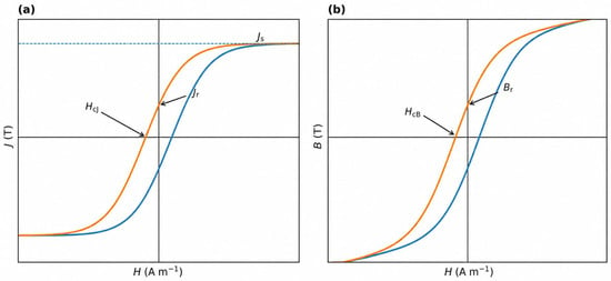
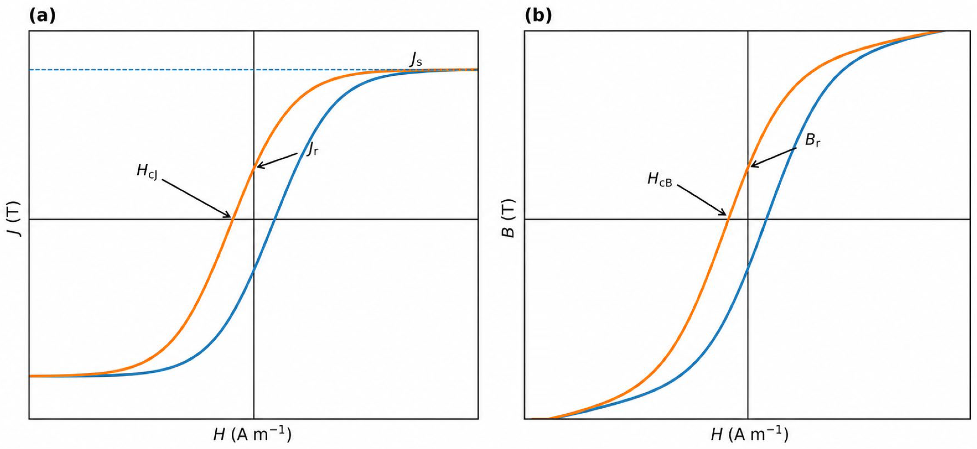
This section is intentionally concise. Its purpose is not to reproduce textbook magnetism, but to define the quantities that control material selection and to explain why reported values cannot be compared without test conditions [2,5,6]. Figure 1 defines the polarization and magnetic flux density loop quantities used throughout the review.
Figure 1.
Schematic polarization J(H) and magnetic flux density B(H) loops. (a) HcJ is the reverse field at which polarization J is zero; Js and Jr are saturation and remanent polarization. (b) HcB is the reverse field at which magnetic flux density B is zero; Br is remanent magnetic flux density. Because B = J + μ0H, Br = Jr at H = 0 when both are expressed in tesla, and HcB and HcJ are usually close for very soft materials measured in closed magnetic circuits. The distinction remains useful because HcJ is a material-centered polarization metric, whereas HcB is read directly from the device-relevant B–H loop. Orange and blue curves indicate descending and ascending branches, respectively.
2.1. Permeability, Coercivity, Saturation Polarization, and Anisotropy
Complex permeability μ* = μ′ − jμ″ describes flux response and magnetic dissipation under small-signal alternating-current (AC) excitation. Its value depends on frequency, excitation amplitude, DC bias, temperature, specimen geometry, and demagnetizing factor. Relative permeability μr describes a material response relative to vacuum, whereas effective permeability μe includes the influence of core geometry, distributed gaps, and processing. Initial permeability, μr, and μe must therefore be reported with their measurement conditions rather than treated as interchangeable material constants. The magnetic loss tangent, tan δμ = μ″/μ′, is useful for small-signal radiofrequency components, whereas power conversion requires large-signal B–H or J–H measurements [2,6,7].
Two coercive fields are relevant. HcJ is obtained from the J(H) loop and reflects the field required to reduce polarization to zero; HcB is obtained from the B(H) loop and includes the applied-field contribution to B. Because B = J + μ0H, HcB and HcJ are often nearly identical for high-permeability soft magnets measured in closed magnetic circuits. The distinction becomes more relevant for open magnetic circuits, appreciable demagnetizing fields, or device analyses in which B = 0 occurs at a finite applied field. Similarly, Br = Jr at H = 0 when both are expressed in tesla; both symbols are retained because material studies commonly report J–H quantities whereas datasheets and device models often use B–H quantities. Low coercivity results from easy domain-wall motion or coherent rotation with minimal pinning. It is controlled by magnetocrystalline anisotropy K, magnetoelastic anisotropy (3/2)λsσ, grain size, internal stress, inclusions, texture, and component geometry. A “perfect crystal” is not an appropriate reference state for practical soft magnets; amorphous alloys can be exceptionally soft precisely because long-range crystalline anisotropy is absent, while nanocrystalline alloys exploit exchange averaging of local anisotropy [4,5].
Saturation magnetization Ms is measured in A m−1. Saturation polarization Js = μ0Ms is reported in tesla and is used here for cross-material comparison. We avoid the ambiguous notation Bs because B continues to increase with μ0H after magnetization approaches saturation. High Js increases allowable flux swing, torque density, and power density, but often conflicts with high resistivity, low magnetostriction, and very low coercivity.
2.2. Core Loss and Dynamic Limitations
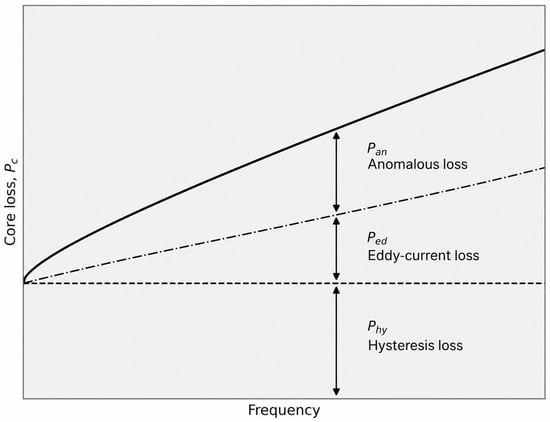
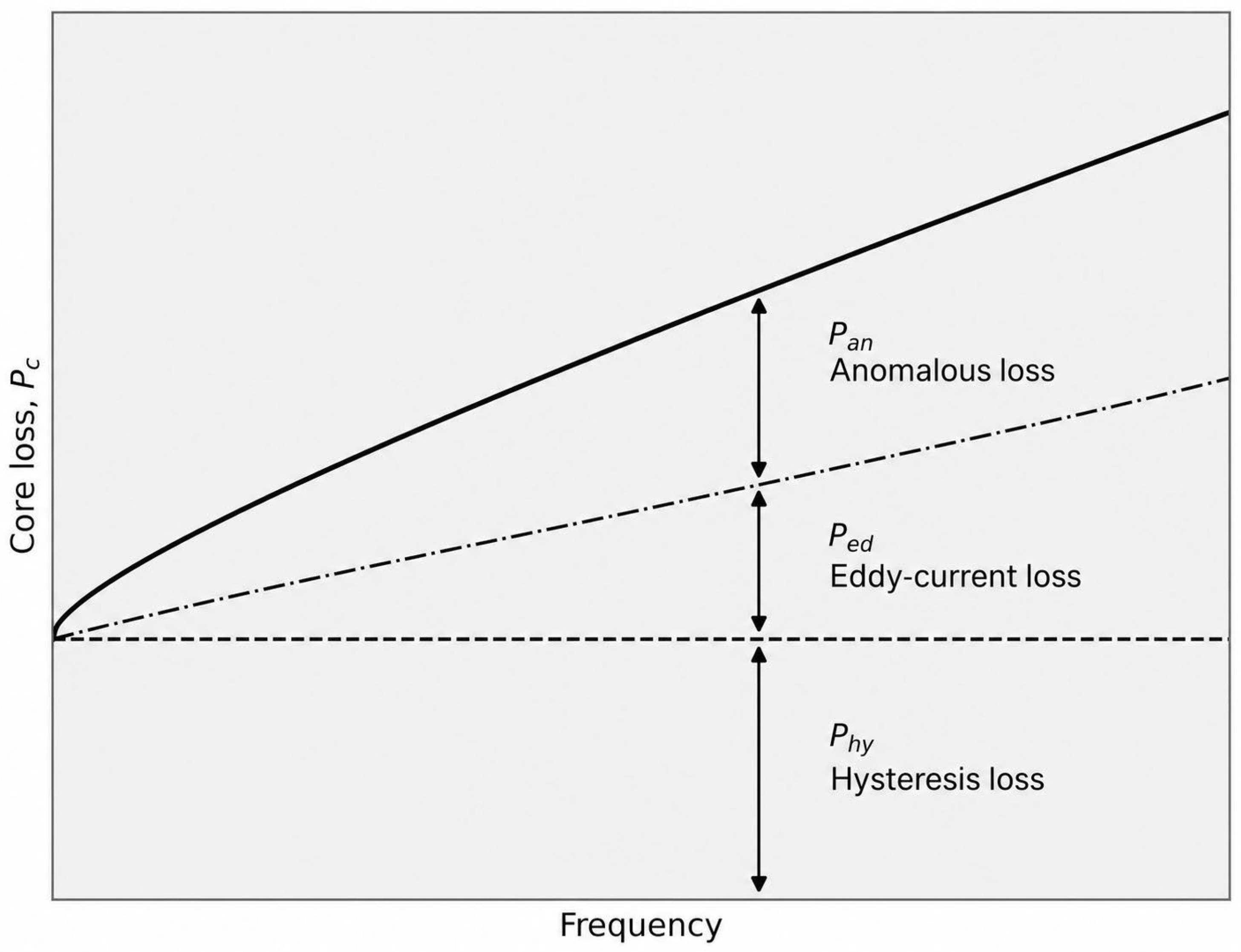
Specific core loss Ps (W kg−1), volumetric core loss Pcv (W m−3), or total component loss (W) must be accompanied by waveform, frequency f, peak magnetic flux density Bp, temperature, DC bias, and specimen geometry. Under sinusoidal excitation, Bertotti-type loss separation is commonly written as Pc = Phy + Ped + Pan, where Phy is the hysteresis loss, Ped is the classical eddy-current loss, and Pan is the anomalous (or excess) loss associated with nonuniform magnetization and moving domain structures [6,8], as shown in Figure 2. The relative magnitudes are not universal; they vary with material, thickness or particle size, excitation, and frequency.
Figure 2.
Schematic frequency dependence of total core loss Pc, separated into hysteresis Phy, anomalous (excess) Pan, and classical eddy-current Ped contributions following the Bertotti framework [6]. The vertical arrows indicate the contribution of each term at a representative frequency. The curves are qualitative and do not imply universal power-law exponents; their relative magnitudes depend on material, geometry, peak magnetic flux density Bp, waveform, temperature, and frequency.
For a conducting lamination under simplified conditions, classical eddy-current loss scales approximately with f2Bp2t2/ρ, where t is the lamination thickness, and ρ is the resistivity. This relation explains the use of thin electrical-steel sheets, amorphous ribbons, insulated particles, and ceramic ferrites. It does not by itself describe excess loss, interlaminar currents, fringing flux, rotational magnetization, nonsinusoidal waveforms, or dimensional resonance. Magnetostriction can also generate dynamic loss and acoustic noise through magnetoelastic coupling; recent work has provided a more explicit formulation of this contribution [8].
2.3. Frequency, Temperature, Stress, and Measurement Conditions
Permeability decreases, and μ″ rises near domain-wall and spin-resonance frequencies. In bulk conductors, skin depth and component dimensions introduce additional dispersion; at microwave frequencies, dimensional resonance may dominate apparent permeability. Temperature changes Js, anisotropy, resistivity, domain structure, and losses. Manganese–zinc (MnZn) ferrites often exhibit a designed loss minimum at an elevated temperature rather than at room temperature, while mechanical stress from cutting, pressing, shrink fitting, or centrifugal loading can increase coercivity and core loss. These dependencies are central to component design and are summarized in Table 1.
Table 1.
Minimum reporting set for soft magnetic material comparison. Each value should be accompanied by the measurement and operating conditions listed in the final column so that data from different materials, specimens, and laboratories can be compared meaningfully.
3. Material Families: Quantitative Cross-Comparison
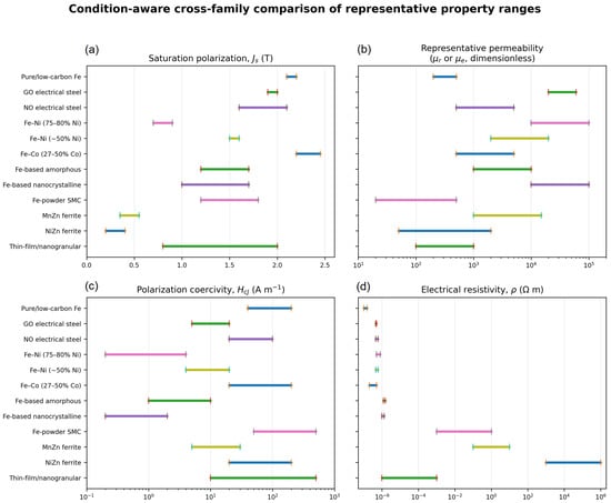
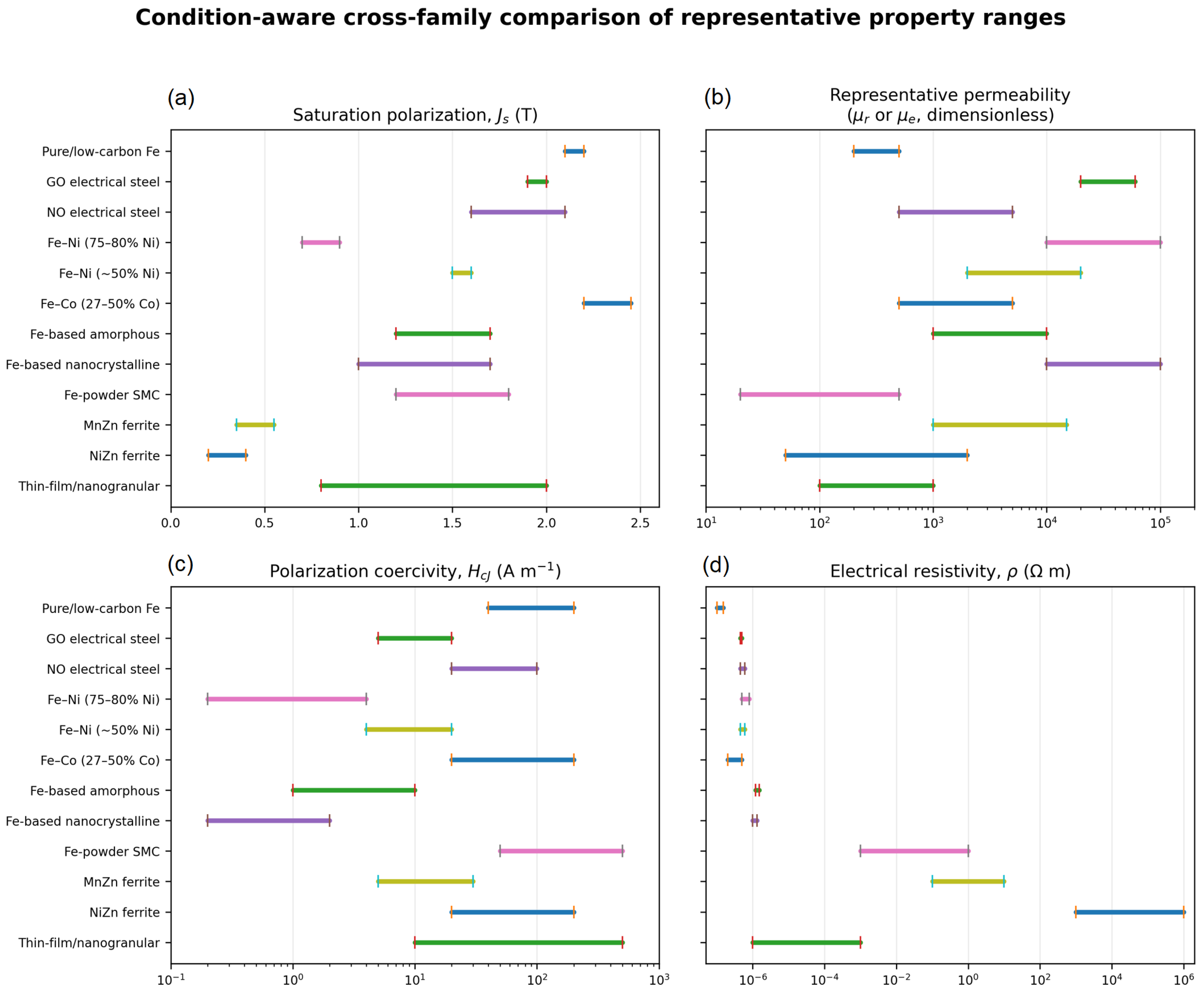
Figure 3 provides an original, author-generated comparison of the principal material families using the ranges compiled in Table 2. All panels now use physically consistent quantities and units: saturation polarization Js, representative relative or effective permeability μr or μe, polarization coercivity HcJ, and electrical resistivity ρ. The reported ranges remain condition-dependent because composition, processing, geometry, and test conditions can shift performance substantially; they should therefore be used as selection guides rather than substitutes for supplier data or component-level measurements. A broader classification of soft magnetic materials is available in [9].
Figure 3.
Condition-aware comparison of representative property ranges for major soft magnetic material families: (a) saturation polarization Js; (b) representative relative or effective permeability μr or μe; (c) polarization coercivity HcJ; and (d) electrical resistivity ρ on a logarithmic scale. The plotted ranges are those reported in Table 2, whose row-specific citations identify the underlying literature. The figure contains no reproduced or adapted third-party graphical elements.
Table 2.
Representative property ranges for major soft magnetic material families. Row-specific citations identify the literature used for each family. The ranges are an author synthesis of published values and indicative design windows; they are not supplier specifications and should not be interchanged across different test conditions. μr denotes relative permeability of a material specimen, whereas μe denotes effective permeability including core geometry and distributed gaps.
3.1. Pure Iron and Electrical Steels
Pure and low-carbon iron are used in relays, solenoids, electromagnets, pole pieces, and magnetic shielding where very high Js, low cost, and straightforward forming are important. Their low resistivity and moderate coercivity limit alternating-current and high-frequency performance, so laminated electrical steels are preferred for most power-frequency transformers and rotating machines [2,3]. Electrical steels combine high Js, low cost, mechanical robustness, and mature high-volume processing. Grain-oriented (GO) steel uses sharp Goss texture to minimize loss along the rolling direction in transformer cores. Non-oriented (NO) steel provides more nearly isotropic in-plane behavior for rotating fields in motors and generators. Relevant subclasses include conventional 2–4 wt.% Si steels, high-silicon grades containing up to approximately 6.5 wt.% Si, high-strength grades for high-speed rotors, and ultrathin laminations for elevated electrical frequencies. Their main limitation is eddy-current and excess loss as frequency, sheet thickness, stress, and harmonic content increase. Punching, laser cutting, interlocking, welding, and shrink fitting can erode part of the intrinsic advantage unless stress relief and assembly are controlled [3,10,11].
3.2. Fe–Ni and Fe–Co Alloys
Fe–Ni alloys cover a wider design space than high-Ni permalloys alone. Alloys containing approximately 75–80% Ni offer extremely high permeability and low HcJ for shielding, sensors, and precision transformers but have Js around 0.7–0.9 T and high material cost. Alloys containing approximately 50% Ni provide higher Js (about 1.5–1.6 T) with lower permeability, while Fe–Ni alloys containing approximately 30–36% Ni are used where thermal expansion, moderate permeability, or a cost–performance balance matters. The commercial name MuMETAL® refers to specific high-permeability Ni–Fe products and is not used generically here [12].
Fe–Co alloys provide the highest Js among widely used soft magnetic alloys. Compositions containing approximately 27–35% Co balance high saturation, strength, and processability, whereas near-equiatomic Fe–Co maximizes Js but is more expensive and can suffer ordering-related brittleness. These alloys are favored in mass- and volume-constrained aerospace actuators, generators, and high-speed machines. Recent precipitate and multicomponent strategies demonstrate that mechanical strength above conventional soft-magnet levels can be achieved without catastrophic coercivity penalties, although scale-up and cost remain important [13,14,15,16].
3.3. Amorphous and Nanocrystalline Alloys
Amorphous ribbons suppress long-range crystalline anisotropy. Their higher resistivity than pure iron is enabled primarily by multicomponent glass-forming chemistries, including additions such as B, Si, P, or C, together with structural disorder; it should not be attributed to the amorphous state alone. Fe-based grades commonly offer Js of approximately 1.2–1.7 T, with low losses at 50/60 Hz and into the kilohertz range. Nanocrystalline alloys are not equivalent to amorphous alloys. Controlled crystallization produces 10–30 nm grains exchange-coupled through the residual amorphous matrix, leading to very low effective anisotropy and HcJ. Magnetostriction differs substantially among alloy systems and heat treatments: near-zero net λs is a major reason for the outstanding softness of optimized nanocrystalline alloys [4,5,17,18]. Their constraints include ribbon thickness, brittleness, stacking factor, stress sensitivity, winding and cutting, and cost [19]. Recent flake-ribbon and composite-core concepts seek to reduce gap and fringing penalties in high-frequency transformers [20,21,22,23].
3.4. Soft Magnetic Composites
Soft magnetic composites (SMCs) consist of insulated magnetic particles consolidated into a three-dimensional (3D) core. Their advantages are near-isotropic magnetic response, suppressed macroscopic eddy currents, net-shape capability, and compatibility with three-dimensional flux paths. Their disadvantages are distributed air gaps, lower effective permeability, insulation breakdown during compaction or annealing, porosity, and particle-scale hysteresis and excess loss [24,25,26,27]. The term SMC should be reserved for composite cores; amorphous ribbon and bulk ferrite are material families, not SMCs.
Recent directions include ferrite-insulated iron particles, easy-plane flake architectures, vortex-state particles, mixed-powder systems, and bioinspired layered composites [28,29,30,31,32,33,34]. Mixed-powder SMCs combine powders with complementary permeability, saturation, DC bias, and loss characteristics. These benefits are not automatic: interparticle coupling, size distribution, insulation continuity, compaction density, and stress must be jointly optimized. Recent FeSiCrB/carbonyl-iron mixtures and ferrite-controlled hybrid composites illustrate the opportunity [31,32,33], while easy-plane and vortex-state composites demonstrate permeability stability into the MHz–GHz regime [28,29,30].
3.5. Ferrites and Microwave Ferrites
MnZn and nickel–zinc (NiZn) ferrites offer electrical resistivity many orders of magnitude above metallic alloys. MnZn ferrites combine relatively high permeability and Js around 0.35–0.55 T and are widely used from tens of kilohertz to the low-megahertz range. NiZn ferrites sacrifice permeability and Js for still higher resistivity and are preferred for higher-frequency electromagnetic interference (EMI) and radiofrequency (RF) components. Power loss is not negligible: it depends strongly on frequency, Bp, temperature, grain size, porosity, stoichiometry, and oxygen partial pressure. Domain engineering can reduce residual loss at MHz frequencies, and recent MnZn compositions maintain Pcv below about 290 kW m−3 over −10 to 120 °C at 300 kHz and 0.1 T, illustrating the importance of wide-temperature rather than room-temperature optimization [35,36].
Microwave ferrites, including substituted spinels and garnets such as yttrium iron garnet (YIG), are selected using ferromagnetic-resonance linewidth, dielectric loss, bias-field requirement, and power handling rather than low-frequency permeability alone. They enable circulators, isolators, phase shifters, and resonators in the MHz–GHz range [37,38,39,40,41].
3.6. Cross-Family Trends and Scientific Bottlenecks
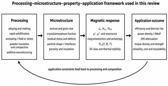
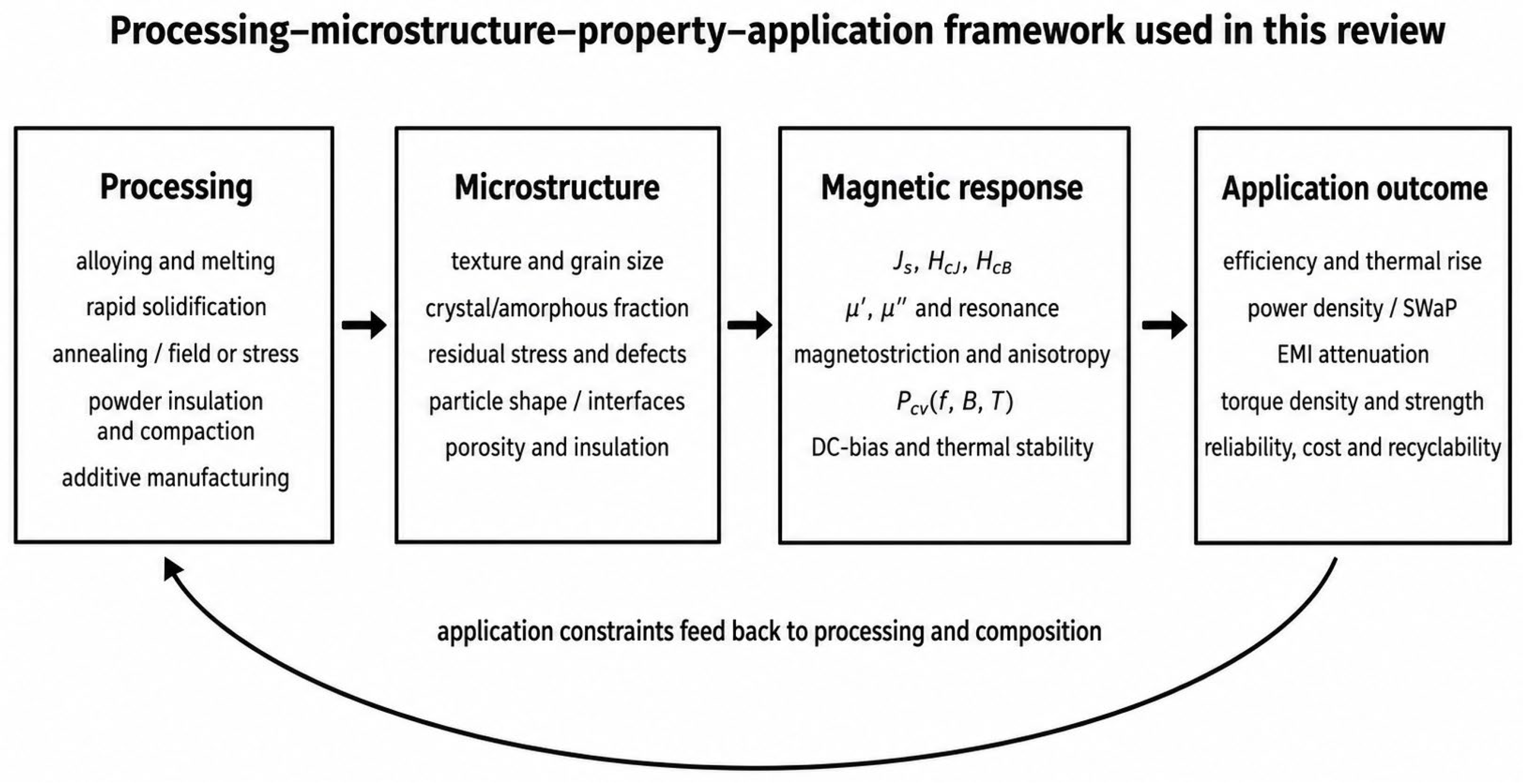
Three trends explain current material development. First, higher frequency shifts the design priority from Js toward resistivity, particle or lamination scale, and dynamic magnetization. Second, higher rotational speed and harsh environments elevate strength, fatigue, corrosion, and stress sensitivity to co-equal status with magnetic loss. Third, component integration makes thermal conductivity, shape freedom, and manufacturing yield as important as coupon-level permeability. The scientific bottleneck is therefore multi-objective control of anisotropy, magnetostriction, interfaces, and electrical isolation across length scales, rather than maximization of a single magnetic parameter. The processing routes, relative costs, industrial maturity, applications, and current development trends of the principal material families are summarized in Table 3. These coupled processing–microstructure–property–application relationships are summarized schematically in Figure 4, emphasizing that application constraints should feed back into materials composition and processing rather than being considered only after material development.
Table 3.
Processing, cost, industrialization, limitations, and current development trends for the principal soft magnetic material families. Row-specific citations identify representative evidence; relative cost and industrial maturity are qualitative author assessments and remain application dependent.
Figure 4.
Processing–microstructure–property–application framework used in this review. Processing routes control texture, grain size, phase fraction, residual stress, defects, interfaces, porosity, and insulation; these features determine saturation polarization, coercivity, complex permeability, magnetostriction, core loss, direct current bias response, and thermal stability. The resulting magnetic response governs efficiency, temperature rise, power density, electromagnetic interference attenuation, mechanical integrity, reliability, cost, and recyclability. The feedback arrow indicates that application constraints should guide composition and processing. EMI, electromagnetic interference; SWaP, size, weight, and power.
4. Application-Driven Material Selection
4.1. Grid Transformers and Electrical Machines
At 50/60 Hz, GO electrical steel remains the default for grid transformers because low loss along the rolling direction, high Js, mature strip production, and low cost outweigh the advantages of more expensive alloys. Amorphous ribbons can reduce no-load loss, but stacking factor, brittleness, audible noise, and manufacturing cost influence adoption. In rotating machines, NO electrical steel dominates because flux rotates and mechanical strength is required. High-speed traction and aerospace rotors impose multiaxial stress and electrical frequencies from hundreds of hertz to several kilohertz; ultrathin high-strength electrical steels, Fe–Co alloys, amorphous stators, and selected SMC topologies are therefore evaluated together with punching damage, centrifugal stress, cooling, and inverter harmonics [11,13,14,15]. Rotational loss arises when the magnetization vector changes direction as well as magnitude; it depends on vector hysteresis, anisotropy, stress, and the field trajectory and cannot generally be inferred from a one-dimensional alternating-flux measurement [6]. The relevant design quantity is therefore rotational and nonsinusoidal component loss, not only Epstein-strip loss.
4.2. Wide-Bandgap Power Electronics and Integrated Magnetics
Wide-bandgap semiconductor switches based on silicon carbide (SiC) and gallium nitride (GaN) permit converter operation from approximately 100 kHz into the multi-megahertz regime. The magnetic component must then sustain acceptable Pcv at the intended Bp and temperature while retaining permeability under DC bias. MnZn ferrites remain competitive at moderate Bp and hundreds of kilohertz; nanocrystalline alloys offer higher Js and permeability for high-power transformers and common-mode chokes; distributed-gap SMCs and powder cores provide DC bias capability; NiZn ferrites and nanogranular films serve higher-frequency, lower-flux functions. Recent gapless nanocrystalline flake-ribbon and laminated nanocrystalline–ferrite concepts illustrate component-level hybridization rather than a single-material solution [21,22,23].
Integrated voltage regulators (IVRs), voltage-regulator modules (VRMs), and power-management integrated circuits (PMICs) place additional constraints on profile, semiconductor-compatible processing, parasitic capacitance, and thermal conductivity. Thin-film Fe–Ni, Fe–Co, amorphous, or nanogranular cores can provide useful μ′ from the MHz to GHz range, but their performance is limited by anisotropy, eddy currents, resonance, and deposition stress [28,42].
4.3. Electromagnetic Interference Suppression, Radiofrequency/Microwave Components, Sensors, and Shielding
Common-mode and differential-mode chokes may have multiple windings and more than two terminals. Their loss can be significant even at relatively low frequency when AC flux, DC bias, or leakage flux is large. Nanocrystalline cores are favored for broadband common-mode impedance; MnZn and NiZn ferrites are selected according to the desired impedance spectrum and temperature; powder cores are used when a distributed gap and DC bias capability are required. Magnetic shielding and weak-field sensors prioritize high permeability, low HcJ, low noise, and stress stability, making high-Ni Fe–Ni, amorphous, and nanocrystalline materials important [47]. Microwave ferrites and engineered composites are selected using resonance linewidth, bias field, and dielectric loss. Wireless power transfer (WPT) systems use ferrite tiles or sheets, nanocrystalline flux guides, and SMC structures to enhance coupling and limit leakage fields; material selection depends on frequency, flux density, misalignment, and thermal cycling [48,49,50].
4.4. Aerospace and Other Extreme Environments
Aerospace electrical systems include conventional 400 Hz power, high-speed generators, more-electric aircraft actuators, electric propulsion motors, DC distribution, and high-frequency onboard converters. These applications can require high Js and mechanical strength at 150–300 °C, stringent size, weight, and power (SWaP) constraints, radiation tolerance, corrosion resistance, and fatigue resistance under vibration. Fe–Co alloys are attractive where mass dominates cost; high-strength electrical steels and recently developed precipitate-strengthened alloys offer alternatives; ferrites and nanocrystalline cores serve high-frequency converters when packaging protects brittle or ceramic components [13,14,15,16]. Clinical magnetic resonance imaging (MRI) systems commonly operate at 1.5, 3, and 7 T, with still higher fields used in research; however, superconducting coils rather than the soft magnetic core usually set the field limit.
4.5. Multi-Criteria Decision Framework
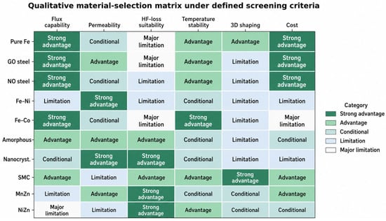
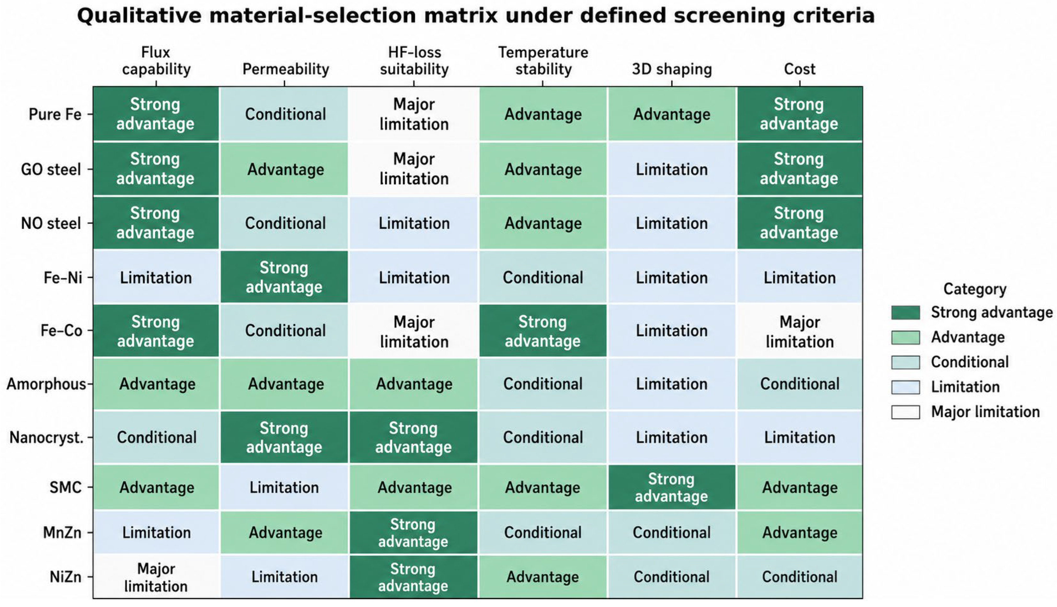
Figure 5 provides a transparent first-pass categorical decision matrix. Five categories—strong advantage, advantage, conditional, limitation, and major limitation—summarize family-level tendencies derived from the property ranges in Table 2, processing and maturity evidence in Table 3, and application envelopes in Table 4. For the high-frequency-loss criterion, the screening envelope is sinusoidal excitation near 100 kHz, Bp ≈ 0.1 T, approximately 100 °C, and zero DC bias. This deliberately narrow envelope should not be extrapolated to other waveforms, frequencies, temperatures, biases, or geometries. The categories must be replaced by supplier or measured component data before design release. A robust selection sequence is to define the waveform and f–Bp–T–DC bias envelope; set the maximum loss and temperature rise; set the minimum Js or inductance; apply mechanical, size, geometry, and environmental constraints; and then compare component cost and manufacturing yield. This sequence prevents high permeability or low room-temperature loss from being used outside the conditions under which they were measured.
Figure 5.
Categorical first-pass material-selection matrix. Each cell summarizes a material-family tendency using the property ranges in Table 2, the processing and maturity evidence in Table 3, and the application windows in Table 4. For high-frequency-loss suitability, the representative screening envelope is sinusoidal excitation near 100 kHz, Bp ≈ 0.1 T, approximately 100 °C, and zero DC bias. Categories range from strong advantage to major limitation. The matrix exposes trade-offs but is not a specification or universal ranking. HF, high frequency; GO, grain-oriented; NO, non-oriented; SMC, soft magnetic composite; MnZn, manganese–zinc; NiZn, nickel–zinc.
Table 4.
Author synthesis of representative application envelopes and material priorities. Row-specific citations identify literature used to establish the ranges. The values are design windows rather than universal standards, direct quotations from a single publication, or supplier specifications.
5. Emerging Demands and Quantified Performance Gaps
5.1. High Frequency and Low Loss
The phrase “high frequency and low loss” is meaningful only with numerical conditions. Based on the comparative ranges in Table 2 and Table 4, we propose Pcv below 0.2–0.5 MW m−3 at 100–500 kHz, 0.1 T, and 100 °C as an author-defined screening target for wide-bandgap (WBG) converter magnetics; it is not a universal specification or a direct quotation from a single source. Published values and commercial grades must be evaluated under matching waveform, temperature, DC bias, and geometry conditions [20,21,22,23,35,36]. For MHz integrated magnetics, Bp is often reduced to tens of millitesla, and μ′ stability becomes as important as large-signal core loss. Key mechanisms include classical and interparticle eddy currents, excess loss, magnetostriction, domain-wall and spin resonance, skin effect, dimensional resonance, fringing flux, and waveform harmonics [8,28,29,30,35,36]. The opportunity lies in controlling particle or lamination scale, anisotropy, insulation, and heat flow together. Cooling is a component-level enabler rather than a new magnetic material and is treated as co-design, not material discovery.
5.2. High Power Density and Miniaturization
Power density requires both high usable flux swing and low thermal resistance. Increasing Js reduces core cross-section, but higher Bp rapidly increases loss. A useful development target for traction or aerospace machines is therefore not maximum Js alone, but maintaining low rotational loss and mechanical integrity at 1.5–2.0 T, electrical frequencies of 1–5 kHz, and temperatures above 150 °C. For compact converters, the target is often stable inductance under DC bias and acceptable temperature rise at 0.1–0.3 T and 0.1–1 MHz. Strong and ductile Fe–Co/Fe–Ni-based multicomponent alloys, ultrathin electrical steels, nanocrystalline ribbons, and 3D SMC geometries address different parts of this envelope [11,13,14,15,16,43].
5.3. Extreme Environments
Extreme-environment performance should be specified by a test envelope: for example, −55 to 200 °C thermal cycling, defined radiation dose, vibration spectrum, corrosive atmosphere, and required fatigue life. Magnetic degradation can arise from temperature-dependent anisotropy, oxidation, binder or insulation failure, stress relaxation, radiation-induced defects, and dimensional instability. Near-term solutions are composition and heat-treatment optimization, coatings, robust insulation, stress management, and qualification. High-temperature precipitate-strengthened soft magnets are approaching application-relevant maturity [14,15]; radiation-hard and self-healing magnetic systems remain less mature.
5.4. Sustainability and Supply Risk
Sustainability priorities differ among families. Electrical steel and ferrites use abundant elements but consume substantial processing energy; high-Ni and Fe–Co alloys carry supply and cost risks; polymer-bound SMCs complicate separation; multilayer and integrated components can be difficult to recycle. A defensible assessment requires embodied energy, yield, lifetime efficiency, repairability, and end-of-life recovery, not composition alone. Near-term opportunities include lower-Co chemistries, recycled iron feedstock, lower-temperature processing, longer component life, and design for disassembly [51].
5.5. Technology Maturity
Not all future concepts deserve equal emphasis. The maturity assignments used here are an author assessment based on evidence of commercial deployment, pilot- or component-scale demonstration, or laboratory proof-of-concept in the cited literature. Wide-temperature ferrites [35,36], advanced nanocrystalline and hybrid cores [19,20,21,22,23], stress-aware electrical steels [11], and selected additive-manufacturing routes [43,44,45,46] are at commercial, pilot, or application demonstration stages. Mixed-powder, easy-plane, and vortex SMCs [28,29,30,31,32,33,34] and high-entropy soft-magnetic fibers [16] remain laboratory-to-pilot concepts. Self-healing magnetic composites [52] and scalable magnetic metamaterials for power components [42,53] remain exploratory. Distinguishing maturity prevents speculative concepts from being presented as near-term industrial solutions.
6. Prioritized Research and Translation Roadmap
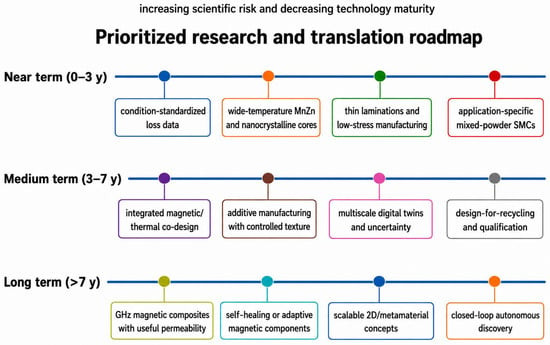
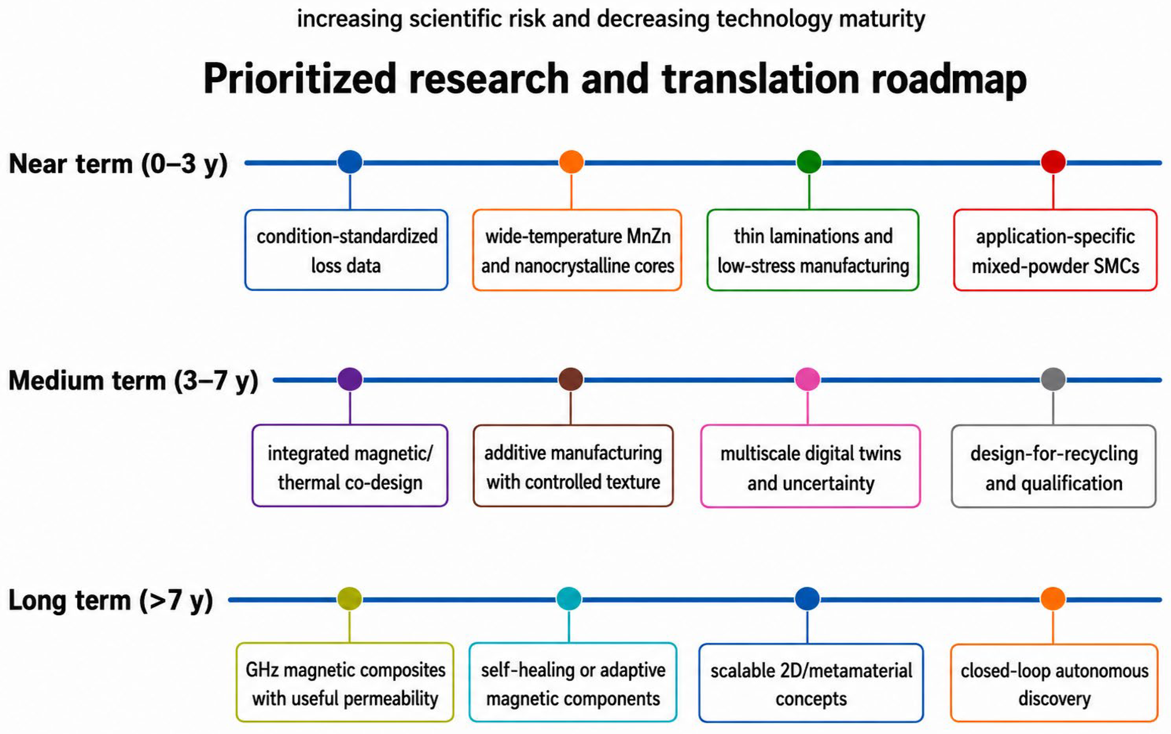
The roadmap in Figure 6 prioritizes activities by time horizon and maturity. Table 5 complements this roadmap by summarizing the current maturity, near-term deliverables, key bottlenecks, application pull, and decision criteria for the principal research directions. The near-term objective is reliable, application-relevant performance rather than another isolated record value. Medium-term work should integrate materials, processing, thermal management, and component topology. Long-term work can explore adaptive and unconventional magnetic architectures, provided that scalable fabrication and realistic loss measurements are built into the research plan.
Figure 6.
Maturity-ranked research and translation roadmap. Near-term (0–3 years) priorities emphasize standardized condition-specific data, wide-temperature ferrite and nanocrystalline cores, low-stress manufacturing, and application-specific mixed-powder soft magnetic composites. Medium-term (3–7 years) priorities emphasize magnetic–thermal co-design, additive manufacturing with controlled texture, validated digital twins, and design for recycling and qualification. Long-term (>7 years) opportunities include GHz composites, adaptive or self-healing components, scalable two-dimensional/metamaterial concepts, and closed-loop autonomous discovery. Scientific risk increases and technology maturity decreases from near- to long-term directions; time horizons are indicative and application-dependent.
6.1. Near-Term Priorities: Standardized Data and Manufacturing Control
First, databases and publications should report loss, μ′, μ″, Js, HcJ, HcB, DC bias, temperature, stress state, geometry, and waveform in a machine-readable form. Second, manufacturing damage must be quantified: cutting, compaction, winding, annealing, joining, and coating should be linked to magnetic-property distributions rather than single mean values. Third, material development should focus on wide-temperature MnZn ferrites, high-strength low-loss electrical steels, lower-stress amorphous/nanocrystalline components, and mixed-powder SMCs with controlled interfaces [10,11,17,19,20,31,32,33,35,36,54].
Table 5.
Author assessment of research maturity based on cited commercial deployment, pilot/component demonstrations, and laboratory proof-of-concept. Row-specific references support each classification; maturity labels are indicative and application dependent.
6.2. Medium-Term Priorities: Co-Design, Additive Manufacturing, and Digital Twins
Magnetic, electrical, mechanical, and thermal design should be coupled from the start. Additive manufacturing can create three-dimensional flux paths and cooling features, but porosity, texture, phase selection, residual stress, and insulation must be controlled. Recent in situ phase engineering of medium-entropy alloys demonstrates that additive processing can be a microstructure-design tool rather than merely a shape-making method [43,44,45,46]. Multiscale models should connect electronic structure and anisotropy to domain behavior, magnetic loss, component fields, and thermal rise. Machine learning is most valuable when constrained by physics, uncertainty, and traceable processing data [55,56].
6.3. Long-Term Priorities: Dynamic, Adaptive, and GHz Magnetics
Longer-term opportunities include vortex and easy-plane architectures with frequency-stable permeability, nanocomposites with controlled exchange and interparticle interactions, scalable metamaterial concepts, and adaptive or self-healing composites [28,29,30,52,53]. Two-dimensional (2D) magnets and soft robotic materials may inspire new functions, but they should not be conflated with bulk power-core requirements. Progress should be measured by component-relevant loss, field handling, reliability, and manufacturability rather than novelty of structure alone.
6.4. Circularity and Qualification
Qualification and circularity must be designed in rather than appended at the end. Promising materials need accelerated thermal, mechanical, electrical, and environmental testing, process-capability data, and component-level failure analysis. Recycling routes should account for coatings, binders, copper windings, adhesives, and mixed-material assemblies. Life-cycle assessment should include avoided operating losses over the service life, which can outweigh differences in embodied processing energy for grid and mobility applications.
7. Conclusions
Soft magnetic material selection is a condition-specific, multi-objective problem. Electrical steels remain dominant where high Js, strength, cost, and manufacturing scale matter; Fe–Ni alloys remain unmatched for weak-field permeability and shielding; Fe–Co alloys address extreme flux-density and SWaP requirements; amorphous and nanocrystalline alloys provide low loss and high permeability from grid-frequency to high-frequency power conversion; SMCs enable three-dimensional flux paths and distributed gaps; and ferrites remain indispensable from switching power supplies to microwave components. None is universally superior.
The most consequential scientific bottlenecks are the coupled control of anisotropy, magnetostriction, interfaces, stress, electrical isolation, and heat flow. Recent progress in strong and ductile soft magnets, wide-temperature MnZn ferrites, easy-plane and vortex composites, mixed-powder SMCs, and additively manufactured multicomponent alloys expands the design space, but maturity differs substantially. Near-term impact will come from standardized, condition-labeled data, manufacturing control, and component-level validation. Medium-term advances require magnetic–thermal–mechanical co-design and trustworthy digital twins. Adaptive, self-healing, and GHz magnetic architectures are longer-term opportunities whose value must be demonstrated under realistic field amplitudes and loss conditions.
The central recommendation is therefore to replace unqualified material rankings with a traceable chain from processing and microstructure to condition-specific properties, component performance, manufacturing yield, cost, and life-cycle benefit. This framework can guide both academic research priorities and industrial material selection.
Author Contributions
R.-K.Z. conceived the review and prepared the draft. Y.S., B.X., R.Z., Y.L. and Z.P. contributed to literature analysis, figures, tables, and critical revision. All authors have read and agreed to the published version of the manuscript.
Funding
This research and APC is funded by the Leading Innovation and Entrepreneurship Team of Zhejiang Province (No. 2023R01020).
Data Availability Statement
No new data were created or analyzed in this study.
Conflicts of Interest
All authors are affiliated with TDG Holding Co., Ltd. and/or Zhejiang Tiantong Electronic Information Materials Research Institute Co., Ltd. All authors declare that the research was conducted in the absence of any commercial or financial relationships that could be construed as a potential conflict of interest.
References
- Silveyra, J.M.; Ferrara, E.; Huber, D.L.; Monson, T.C. Soft magnetic materials for a sustainable and electrified world. Science 2018, 362, eaao0195. [Google Scholar] [CrossRef] [Scilit] [PubMed]
- Coey, J.M.D. Magnetism and Magnetic Materials; Cambridge University Press: Cambridge, UK, 2010. [Google Scholar]
- Mazaleyrat, F. Soft Magnetic Materials and Applications. In Handbook of Magnetism and Magnetic Materials; Coey, J.M.D., Parkin, S.S.P., Eds.; Springer: Cham, Switzerland, 2021; pp. 1435–1487. [Google Scholar]
- Herzer, G. Modern soft magnets: Amorphous and nanocrystalline materials. Acta Mater. 2013, 61, 718–734. [Google Scholar] [CrossRef] [Scilit]
- Herzer, G. Grain size dependence of coercivity and permeability in nanocrystalline ferromagnets. IEEE Trans. Magn. 1990, 26, 1397–1402. [Google Scholar] [CrossRef] [Scilit]
- Bertotti, G. Hysteresis in Magnetism: For Physicists, Materials Scientists, and Engineers; Academic Press: San Diego, CA, USA, 1998. [Google Scholar]
- Calvo-de la Rosa, J.; Tejada, J.; Lousa, A. Structural and impedance spectroscopy characterization of soft magnetic materials. J. Magn. Magn. Mater. 2019, 475, 570–578. [Google Scholar] [CrossRef] [Scilit]
- Tsukahara, H.; Huang, H.; Suzuki, K.; Ono, K. Formulation of energy loss due to magnetostriction to design ultraefficient soft magnets. NPG Asia Mater. 2024, 16, 19. [Google Scholar] [CrossRef] [Scilit]
- Inoue, A.; Kong, F. Soft Magnetic Materials. In Encyclopedia of Smart Materials; Olabi, A.-G., Ed.; Elsevier: Oxford, UK, 2022; pp. 10–23. [Google Scholar]
- Ouyang, G.; Chen, X.; Liang, Y.; Macziewski, C.; Cui, J. Review of Fe–6.5 wt.% Si high-silicon steel—A promising soft magnetic material for sub-kHz application. J. Magn. Magn. Mater. 2019, 481, 234–250. [Google Scholar] [CrossRef] [Scilit]
- Yamazaki, K.; Ishikawa, K.; Ohguchi, H.; Imamori, S.; Shuto, M. Magnetic property investigation of high-strength electrical steel sheet applied to interior permanent magnet synchronous motors considering multiaxial stress caused by centrifugal force. IEEE Trans. Magn. 2023, 59, 2001405. [Google Scholar] [CrossRef] [Scilit]
- Pfeifer, F.; Radeloff, C. Soft magnetic Ni–Fe and Co–Fe alloys—Some physical and metallurgical aspects. J. Magn. Magn. Mater. 1980, 19, 190–207. [Google Scholar] [CrossRef] [Scilit]
- Han, L.; Maccari, F.; Souza Filho, I.R.; Peter, N.J.; Wei, Y.; Gault, B.; Gutfleisch, O.; Li, Z.; Raabe, D. A mechanically strong and ductile soft magnet with extremely low coercivity. Nature 2022, 608, 310–316. [Google Scholar] [CrossRef] [Scilit] [PubMed]
- Han, L.; Maccari, F.; Soldatov, I.; Peter, N.J.; Souza Filho, I.R.; Schäfer, R.; Gutfleisch, O.; Li, Z.; Raabe, D. Strong and ductile high temperature soft magnets through Widmanstätten precipitates. Nat. Commun. 2023, 14, 8176. [Google Scholar] [CrossRef] [Scilit] [PubMed]
- Han, L.; Peter, N.J.; Maccari, F.; Kovács, A.; Wang, J.; Zhang, Y.; Xie, R.; Wu, Y.; Schwaiger, R.; Zhang, H.; et al. Two-gigapascal-strong ductile soft magnets. Nat. Commun. 2024, 15, 10119. [Google Scholar] [CrossRef] [Scilit] [PubMed]
- Ma, Y.; Kou, Z.; Yang, W.; He, A.; Dong, Y.; Man, Q.; Liu, H.; Li, Z.; Inoue, A.; Li, J. A one-step fabrication of soft-magnetic high entropy alloy fiber with excellent strength and flexibility. Nat. Commun. 2024, 15, 10549. [Google Scholar] [CrossRef] [Scilit] [PubMed]
- Wang, A.; Zhao, C.; He, A.; Men, H.; Chang, C.; Wang, X. Composition design of high Bs Fe-based amorphous alloys with good amorphous-forming ability. J. Alloys Compd. 2016, 656, 729–734. [Google Scholar] [CrossRef] [Scilit]
- Yoshizawa, Y.; Oguma, S.; Yamauchi, K. New Fe-based soft magnetic alloys composed of ultrafine grain structure. J. Appl. Phys. 1988, 64, 6044–6046. [Google Scholar] [CrossRef] [Scilit]
- Bruno, N.M.; Adoo, N.A.; Meakins, E.; Keylin, V.; Feichter, G.E.; Noebe, R.D. The effect of stress annealing on the mechanical and magnetic properties of Fe-based metal-amorphous nanocomposite soft magnetic alloys. J. Non-Cryst. Solids 2023, 600, 122037. [Google Scholar] [CrossRef] [Scilit]
- Jiang, C.; Li, X.; Ghosh, S.S.; Zhao, H.; Shen, Y.; Long, T. Nanocrystalline powder cores for high-power high-frequency power electronics applications. IEEE Trans. Power Electron. 2020, 35, 10821–10830. [Google Scholar] [CrossRef] [Scilit]
- Umair, M.M.; Muhammad, E.; Atef, T.M.; Ashraf, A.; Park, J.-H. Loss analysis of nanocrystalline cores for high-frequency transformer in power electronics circuits. J. Electr. Eng. Technol. 2024, 19, 1257–1266. [Google Scholar] [CrossRef] [Scilit]
- Li, X.; Ren, X.; Luo, Z.; Hu, B.; Liu, C.; Jiang, C.; Long, T. Gapless transformer design by using nanocrystalline flake ribbon. IEEE J. Emerg. Sel. Top. Power Electron. 2025, 13, 798–808. [Google Scholar] [CrossRef] [Scilit]
- Xia, N.; Chen, M.; Mao, X.; Yan, S.; Ma, H. Laminated nanocrystalline–ferrite high saturation magnetic flux density composite core for use in high-frequency transformers. J. Power Electron. 2024, 24, 1374–1384. [Google Scholar] [CrossRef] [Scilit]
- Shokrollahi, H.; Janghorban, K. Soft magnetic composite materials (SMCs). J. Mater. Process. Technol. 2007, 189, 1–12. [Google Scholar] [CrossRef] [Scilit]
- Perigo, E.A.; Weidenfeller, B.; Kollár, P.; Füzer, J. Past, present, and future of soft magnetic composites. Appl. Phys. Rev. 2018, 5, 031301. [Google Scholar] [CrossRef] [Scilit]
- Sunday, K.J.; Taheri, M.L. Soft magnetic composites: Recent advancements in the technology. Met. Powder Rep. 2017, 72, 425–429. [Google Scholar] [CrossRef] [Scilit]
- Schoppa, A.; Delarbre, P. Soft magnetic powder composites and potential applications in modern electric machines and devices. IEEE Trans. Magn. 2014, 50, 2004304. [Google Scholar] [CrossRef] [Scilit]
- Bai, G.; Sun, J.; Zhang, Z.; Liu, X.; Bandaru, S.; Liu, W.; Li, Z.; Li, H.; Wang, N.; Zhang, X. Vortex-based soft magnetic composite with ultrastable permeability up to gigahertz frequencies. Nat. Commun. 2024, 15, 2238. [Google Scholar] [CrossRef] [Scilit] [PubMed]
- Wu, P.; Cui, J.; Wang, K.; Huang, Y.; Qiao, L.; Wang, T.; Li, F. Study on the influence of the degree of the easy-plane orientation on the high-frequency magnetic properties and power loss of SMC in the MHz band. Acta Mater. 2024, 275, 120041. [Google Scholar] [CrossRef] [Scilit]
- Zhang, H.; Wang, K.; Huang, Y.; He, D.; Wang, Y.; Wang, T. The excess loss analysis of an easy-plane FeSiAl@SiO2 soft magnetic composite with high permeability. J. Magn. Magn. Mater. 2023, 588, 171471. [Google Scholar] [CrossRef] [Scilit]
- Dobák, S.; Kollár, P.; Füzer, J.; Bureš, R.; Fáberová, M. On the ferrite-controlled iron coupling for enhanced soft magnetic hybrid composites via first-order reversal curves. Acta Mater. 2023, 246, 118667. [Google Scholar] [CrossRef] [Scilit]
- Han, J.W.; Kim, S.W.; Kim, C.P.; Choi, D.H.; Kim, S.; Lee, B.W. Formation of mixed-powder composites with improved magnetic properties by adding carbonyl iron powders to FeSiCrB amorphous powder. J. Magn. Magn. Mater. 2023, 565, 170181. [Google Scholar] [CrossRef] [Scilit]
- Liu, J.; Dong, Y.; Wang, P.; Zhu, Z.; Pang, J.; Li, X.; Zhang, J. Improved high-frequency magnetic properties of FeSiBCCr amorphous soft magnetic composites by adding carbonyl iron powders. J. Non-Cryst. Solids 2023, 605, 122166. [Google Scholar] [CrossRef] [Scilit]
- Li, W.; Cai, H.; Kang, Y.; Ying, Y.; Yu, J.; Zheng, J.; Qiao, L.; Jiang, Y.; Che, S. High permeability and low loss bioinspired soft magnetic composites with nacre-like structure for high-frequency applications. Acta Mater. 2019, 167, 267–274. [Google Scholar] [CrossRef] [Scilit]
- Wu, G.; Yu, Z.; Guo, R.; Wang, Z.; Wang, H.; Hu, Z.; Liu, M. Effects of magnetic domain morphology on the magnetic spectrum and high-frequency core losses of MnZn ferrites. J. Am. Ceram. Soc. 2024, 107, 1117–1126. [Google Scholar] [CrossRef] [Scilit]
- Ying, Y.; Chen, G.; Li, Z.; Zheng, J.; Yu, J.; Qiao, L.; Li, W.; Li, J.; Wakiya, N.; Yamaguchi, M.; et al. Magnetic and dielectric properties of low-loss MnZn ferrites with wide temperature stability. J. Am. Ceram. Soc. 2025, 108, e20137. [Google Scholar] [CrossRef] [Scilit]
- Goldman, A. Modern Ferrite Technology, 2nd ed.; Springer: New York, NY, USA, 2006. [Google Scholar]
- Snelling, E.C. Soft Ferrites: Properties and Applications, 2nd ed.; Butterworths: London, UK, 1988. [Google Scholar]
- Harris, V.G.; Geiler, A.; Chen, Y.; Yoon, S.D.; Wu, M.; Yang, A.; Chen, Z.; He, P.; Parimi, P.V.; Zuo, X.; et al. Recent advances in processing and applications of microwave ferrites. J. Magn. Magn. Mater. 2009, 321, 2035–2047. [Google Scholar] [CrossRef] [Scilit]
- Houbi, A.; Aldashevich, Z.A.; Atassi, Y.; Bagasharova, Z.T.; Saule, M.; Kubanych, K. Microwave absorbing properties of ferrites and their composites: A review. J. Magn. Magn. Mater. 2021, 529, 167839. [Google Scholar] [CrossRef] [Scilit]
- Reddy, M.P.; Madhuri, W.; Reddy, N.R.; Kumar, K.V.S.; Murthy, V.R.K.; Reddy, R.R. Influence of copper substitution on magnetic and electrical properties of MgCuZn ferrite prepared by microwave sintering. Mater. Sci. Eng. C 2010, 30, 1094–1099. [Google Scholar] [CrossRef] [Scilit]
- Fergen, I.; Seemann, K.; von der Weth, A.; Schüppen, A. Soft ferromagnetic thin films for high-frequency applications. J. Magn. Magn. Mater. 2002, 242–245, 146–151. [Google Scholar] [CrossRef] [Scilit]
- Cao, Z.; Zhang, P.; An, B.; Li, D.; Yu, Y.; Pan, J.; Zhang, C.; Liu, L. In situ phase engineering during additive manufacturing enables high-performance soft-magnetic medium-entropy alloys. Nat. Commun. 2024, 15, 9747. [Google Scholar] [CrossRef] [Scilit] [PubMed]
- Adamczyk, J.M.; Birchall, S.E.; Rothermel, E.T.; Whetten, S.R.; Barrick, E.J.; Pearce, C.J.; Delaney, R.E.; Pegues, J.W.; Johnson, K.L.; Susan, D.F.; et al. Characterization of Fe–6Si soft magnetic alloy produced by laser-directed energy deposition additive manufacturing. JOM 2024, 76, 863–874. [Google Scholar] [CrossRef] [Scilit]
- Goll, D.; Schuller, D.; Martinek, G.; Kunert, T.; Schurr, J.; Sinz, C.; Schubert, T.; Bernthaler, T.; Riegel, H.; Schneider, G. Additive manufacturing of soft magnetic materials and components. Addit. Manuf. 2019, 27, 428–439. [Google Scholar] [CrossRef] [Scilit]
- Wei, X.; Jin, M.-L.; Yang, H.; Wang, X.-X.; Long, Y.-Z.; Chen, Z. Advances in 3D printing of magnetic materials: Fabrication, properties, and applications. J. Adv. Ceram. 2022, 11, 665–701. [Google Scholar] [CrossRef] [Scilit]
- Khan, M.A.; Sun, J.; Li, B.; Przybysz, A.; Kosel, J. Magnetic sensors—A review and recent technologies. Eng. Res. Express 2021, 3, 022005. [Google Scholar] [CrossRef] [Scilit]
- Bi, Z.; Kan, T.; Mi, C.C.; Zhang, Y.; Zhao, Z.; Keoleian, G.A. A review of wireless power transfer for electric vehicles: Prospects to enhance sustainable mobility. Appl. Energy 2016, 179, 413–425. [Google Scholar] [CrossRef] [Scilit]
- Zhang, Z.; Pang, H.; Georgiadis, A.; Cecati, C. Wireless power transfer—An overview. IEEE Trans. Ind. Electron. 2019, 66, 1044–1058. [Google Scholar] [CrossRef] [Scilit]
- Lee, I.G.; Kim, N.; Cho, I.K.; Hong, I.P. Design of a patterned soft magnetic structure to reduce magnetic flux leakage of magnetic induction wireless power transfer systems. IEEE Trans. Electromagn. Compat. 2017, 59, 1856–1863. [Google Scholar] [CrossRef] [Scilit]
- Raabe, D. The materials science behind sustainable metals and alloys. Chem. Rev. 2023, 123, 2436–2608. [Google Scholar] [CrossRef] [Scilit] [PubMed]
- Cerdan, K.; Moya, C.; Van Puyvelde, P.; Bruylants, G.; Brancart, J. Magnetic self-healing composites: Synthesis and applications. Molecules 2022, 27, 3796. [Google Scholar] [CrossRef] [Scilit] [PubMed]
- Radkovskaya, A.; Petrov, P.; Kiriushechkina, S.; Satskiy, A.; Ivanyukovich, M.; Vakulenko, A.; Prudnikov, V.; Kotelnikova, O.; Korolev, A.; Zakharov, P. Magnetic metamaterials: Coupling and permeability. J. Magn. Magn. Mater. 2018, 459, 187–190. [Google Scholar] [CrossRef] [Scilit]
- Gao, M.C.; Miracle, D.B.; Maurice, D.; Yan, X.; Zhang, Y.; Hawk, J.A. High-entropy functional materials. J. Mater. Res. 2018, 33, 3138–3155. [Google Scholar] [CrossRef] [Scilit]
- Singh, P.; Del Rose, T.; Palasyuk, A.; Mudryk, Y. Physics-informed machine-learning prediction of Curie temperatures and its promise for guiding the discovery of functional magnetic materials. Chem. Mater. 2023, 35, 6304–6312. [Google Scholar] [CrossRef] [Scilit]
- Curtarolo, S.; Hart, G.L.W.; Nardelli, M.B.; Mingo, N.; Sanvito, S.; Levy, O. The high-throughput highway to computational materials design. Nat. Mater. 2013, 12, 191–201. [Google Scholar] [CrossRef] [Scilit] [PubMed]

Disclaimer/Publisher’s Note: The statements, opinions and data contained in all publications are solely those of the individual author(s) and contributor(s) and not of MDPI and/or the editor(s). MDPI and/or the editor(s) disclaim responsibility for any injury to people or property resulting from any ideas, methods, instructions or products referred to in the content. |
© 2026 by the authors. Licensee MDPI, Basel, Switzerland. This article is an open access article distributed under the terms and conditions of the Creative Commons Attribution (CC BY) license.