Abstract
The indoor space model is the foundation of most indoor location-based services (LBS). A complete indoor space model includes floor-level paths and non-level paths. The latter includes passages connecting different floors or elevations such as stairs, elevators, escalators, and ramps. Most related studies have merely discussed the modeling and generation of floor-level paths, while those considering non-level paths usually simplify the formation and generation of non-level paths, especially stairs, which play an important role in emergency evacuation and response. Although the algorithm proposed by i-GIT approach, which considers both floor-level and non-level paths, can automatically generate paths of straight stairs, it is not applicable to the spiral stairs and winder stairs that are common in town houses and other public buildings. This study proposes a novel approach to generate high-accuracy stair paths that can support straight, spiral, and winder stairs. To implement and verify the proposed algorithm, 54 straight and spiral stairs provided by Autodesk Revit’s official website and three self-built winder stairs are used as test cases. The test results show that the algorithm can successfully produce the stair paths of most test cases (49/50), which comprehensively extends the applicability of the proposed algorithm.
1. Introduction
As spatial information is becoming readily available and commonplace, location-based services (LBS) have expanded from outdoor to indoor [1,2,3,4,5]. The so-called indoor LBS refers to location-based services that occur in indoor spaces [4]. Commonly seen applications come in three major categories: wayfinding and tracking [6,7,8,9], resource management [10], and emergency response [11,12,13]. These services and applications are based on an “interior space model” composed of paths (i.e., edges) and nodes [14]. There are also two types of paths, “floor-level paths” and “non-floor level paths”. The latter are stairs, elevators, escalators, ramps, etc. [1]. Unlike an outdoor space, an indoor space is relatively closed, narrow, and private; the space structure is complex, and movement within is in 3D [15]. Many studies have proposed different indoor space models, each within their applicable field [11,12,13,14,15,16,17,18,19,20,21]. Different models have differences in aspects like spatial topology, location reference, model accuracy, routing algorithm, and visualization of the path [15]. Therefore, there are also many scholars studying the methods of generation for different spatial data models [1,5,22,23,24,25,26].
In recent years, due to the frequency of terrorist incidents and disasters, the study of emergency evacuations has become particularly important. Many scholars have proposed solutions for emergency evacuation. Lee proposed a network representation of a building and a 3D mapping method to provide navigation guidance for rescue personnel during an emergency [11]. Tashakkori et al. explored the spatial awareness needed for a successful emergency response, and introduced an indoor emergency spatial model based on Industry Foundation Classes (IFC) to increase responders’ perception of the indoor area, decrease indoor travel times, and optimize route finding in an emergency [12]. Another indoor space model that supports evacuation routing and assessment was proposed [13] with a feature that includes static indoor spatial objects as well as dynamic information, such as outdoor traffic, fire spread, and movement of rescue personnel. Although these studies were effective in indoor route planning for emergency rescue and evacuation, they neglected the important role of stairs in emergency response by simplifying the model of a stair path [11,12,13]. Research has found that, since stairs are the only safe vertical transition points during emergencies such as fires and earthquakes, casualties and property damage are likely to occur in a staircase as a result of congestion [27]. However, most research has focused on the 2D plan of a building, in which vertical passages and obstacles are ignored [28]. Researchers have argued that, in order to improve the efficiency, capacity, and safety of indoor emergency evacuation, a simulation model must be quantitatively correct to match human motion in the real world [29,30,31]. Most indoor space models are 2.5D approaches representing 3D spaces as multiple layers of a 2D plan with non-level paths such as elevators and stairs, which are usually represented as vertical paths [13,17,18,23,28]. This type of 2.5D model is not suitable for emergency response applications and urgently needs improvement. However, not only is manually generating high-accuracy non-level paths costly, but it is also prone to human errors [15,32].
Lin et al. [26] proposed an indoor topology generation framework named intelligent generation of indoor topology (i-GIT). Based on IFC models, i-GIT can automatically construct 3D indoor networks including level and non-level paths. Non-level paths include straight stairs [1,33], ramps, and elevators [34], so it is applicable for those indoor LBS requiring a high-accuracy indoor space model, such as emergency response systems. However, the current algorithm of i-GIT only supports straight stairs, as shown on the left side of Figure 1, and it does not support the spiral and winder stairs that are commonly seen in town houses or public buildings. These two types of stairs usually have no stair landing between runs. Moreover, not only will the stair steps change their orientation with height, but the shape and size of the steps may also not be consistent. These features undoubtedly increase the difficulty of algorithm design [18,32].
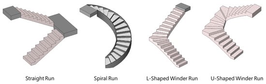
Figure 1.
Categories of common stair runs.
This study proposes an entirely new algorithmic logic that is not only applicable to all straight stairs supported by the i-GIT algorithm, but also supports two new types of stairs, spiral and winder stairs. The newly proposed algorithm greatly improves its applicability to stairs. The structure of the following paper is as follows. Section 2 reviews previous studies related to indoor spaces with a focus on emergency response, describes the difficulties and limitations encountered in existing research on generating stair paths and, finally, briefly describes the algorithm of i-GIT for generating the stair paths and its applications. Section 3 describes the types of stairs, variations in stair structure, and important modeling parameters that should be considered in the stair path generation algorithm. Section 4 introduces the algorithmic logic and Section 5 verifies the algorithm with actual cases in detail. Section 6 gives the conclusion and recommendations for subsequent research.
2. Related Works
2.1. Indoor Spaces for Emergency Response
An indoor space is defined as a closed environment formed by physical elements where human activities take place [2]. Unlike objects in outdoor spaces that can be referenced with an absolute 2D coordinate system, indoor objects are usually described in 3D and referenced in relative terms by indoor spaces with a sematic meaning, such as rooms, corridors, or staircases [2,4]. Since the demand for spatial information about indoor spaces has been increasing in recent decades [3], many studies on modeling indoor spaces have been conducted and these can be divided into three categories: (1) data modeling of indoor spaces [3,21], (2) generation of indoor space models [22,23], and (3) applications of indoor space models [21]. Studies of the first category focus on expressing the indoor space with a data model, which conceptually supports the applications established by studies in the third category. Studies on generating indoor space models deal with the automatic construction or production of a model for practical uses.
Many studies have proposed different indoor space models. These models can be roughly divided into two categories: geometric-based approaches and symbolic-based approaches [14]. The geometric-based approaches, also known as metric approaches or coordinate-based approaches, divide the indoor space into a dense grid. Each cell in this grid represents a position in the indoor space. The shape of the cell can be regular or irregular. On the other hand, symbolic-based approaches express the indoor space in the form of topological structures, connectivity graphs, or hierarchies possessing context-aware spatial semantics. The most common symbolic-based approach is a navigation graph, which expresses an indoor space as nodes and edges. Nodes represent indoor points of interest (POIs), whereas edges represent links between nodes [11,16,18,19]. Although a navigation graph cannot achieve an accuracy as high as that of a grid model, it has both spatial semantics and coarse-level geometric information, so navigation graphs are widely used by various context-aware navigation services.
Different models have their own applicable fields, with differences in aspects such as spatial topology, location reference, model accuracy, routing algorithm, and visualization of the path. To implement an indoor space model in a real-world application, it requires a physical process to represent a real building according to the definition of the model. However, a manual process is often costly and prone to human errors, so many studies are exploring how to automate the abovementioned process. Since the indoor space model constructed using geometric-based approaches is relatively simple, most studies focus on generation of symbolic-based models [1,5,22,23,24,25]. Scholars divide these algorithms into three categories: visibility graph, straight skeletons, and dual structures. However, most of them were designed for floor-level paths, while there has been little research found on non-level paths.
Lin et al. proposed an indoor topology generation framework called i-GIT, which can automatically construct indoor networks including level and non-level paths [26]. The i-GIT algorithm only needs to read a 3D building model that complies with the IFC2x, 2x2, or 2x3 formats. With little manual pre-processing, the algorithm can automatically generate a graph-based indoor space model of multi-story buildings [26]. The novelty of the i-GIT approach lies in automatic generation of non-floor paths, such as stairs, ramps, and elevators. Section 2.2 will introduce the algorithms generating stair flight paths in detail.
According to scholars [3,4], studies on indoor context-aware applications can be divided into three major categories: wayfinding and tracking [6,7,8,9], resource management [10], and emergency response [11,12,13]. Among the wayfinding and tracking studies, Yan et al. developed a gaming system that integrates building information modeling (BIM) and computer games for interactive architectural visualization [6]. Lin et al. proposed an IFC-based method to avoid the complexity of 3D representations for path planning in indoor spaces [7]. Another study dealt with indoor path planning considering obstacles based on a BIM/IFC model [9]. In the field of resource management, an information system that facilitates the use of BIM for operational tasks of facility management was proposed [10] and Kang et al. also integrated BIM models into a GIS-based system for facility management [35]. These studies facilitate the everyday operations of several domains including visiting businesses in office buildings, shopping in large malls, transferring in transportation stations, and maintenance activities in buildings [3].
Due to the recent terrorist incidents and disasters around the world, studies of emergency evacuations and response have rapidly emerged in the last decade. Lee proposed an indoor network model and a 3D mapping method to facilitate evacuation during an emergency in built environments [11]. Tashakkori et al. also introduced an indoor model based on IFC for emergency responders to easily perceive the indoor environment, decrease travel times, and optimize route finding for evacuation [12]. Another indoor space model that supports evacuation routing and assessment was proposed [13] that considered both static spatial objects and dynamic information, such as outdoor traffic, fire spread, and movement of rescue personnel.
These studies were proved to be effective in route planning for emergency response and evacuation in built environments; however, most of them simplified the modeling of stairs, which overlooked the impact of stairs in emergency response [11,12,13]. Research [27] has found that stairs are the only safe transition passage between floors during emergencies, so casualties and property damage are likely to occur in a staircase because of congestion. Most research that used 2.5D space models has obviously ignored the importance of those passages in emergency incidents, such as fires and earthquakes [28]. Therefore, researchers have argued that, in order to improve the efficiency, capacity, and safety of indoor emergency evacuation, a simulation model must be quantitatively correct to match human motion in the real world [29,30,31]. The next section will describe existing research on how to generate stair flight paths and the difficulties encountered.
2.2. Generation of Stair Paths
During emergency evacuation, stairs are often prone to crowding. Compared with level passages, slanted stairs are more likely to cause casualties and property damage in emergency situations. Therefore, researchers [27] have pointed out that, since the evacuation performance of stairs is closely related to the safety of pedestrians, stairs should be regarded as a critical area during emergency evacuation and response.
More and more consideration has been given to the behavior of occupant flows on staircases during high-rise building evacuations in recent studies [30]. Galea et al. [36] conducted a computer simulation revealing that both the merging behavior of occupant flows on staircases and the layout of the staircases have an impact on the speed of the occupants and the flow rate of the occupants entering the landing on a floor. Sano et al. [30] investigated the evacuation behavior of evacuees on the staircase of a 25-story high-rise building, and found that evacuee density on the landings in the moving situation was different from that in the stopped situation when the staircase was fully crowded. They also observed that the results will vary depending on the geometry of the staircase and the location of the exit. Köster et al. [31] argued that current models of evacuee motion on stairs adopted by most evacuation studies do not sufficiently match human motion. A simulation model for real-world applications should be quantitatively correct in order to improve efficiency, capacity, and safety of evacuation. In another study discussing indoor navigation for disabled people, researchers found that the layout of ramps and stairs influences the mobility of wheelchair riders, and therefore a more accurate model of ramps and stairs is needed for in-depth analysis [21].
However, among studies of indoor space models and emergency responses, vertical passages between building floors often merely included elevators. Those studies considering stairs, on the other hand, oversimplified the modeling of stairs. Most stairs have landings between runs, which will greatly influence humans’ travel; therefore, the length of a stair path should not be the only consideration when providing an emergency evacuation plan. Xiong et al. [13] conducted an emergency evacuation simulation using a grid-based indoor space model, whereby the stair flight paths are simplified to vertical lines. Teo and Cho [17] proposed a network model called a multiple-purpose geometric network model (MGNM) and stated that stairs are important connecting paths between different floors. However, their study did not consider the detailed geometry of stairs. In the same way, other studies using a dual structure as a spatial data model have also simplified the modeling of the stair paths [18,23,28].
One of the reasons for simplifying the stair paths is that the generation of high-accuracy paths is not only costly, but also prone to human errors. Tsiliakou and Dimopoulou [32] manually created accurate stair paths when implementing an indoor route planning system. However, they discovered that it is vital to snap each end of a stair flight path correctly both in 2D and 3D to the ends of other paths on the floor, but this is a challenging task since the path creation occurs in 3D space.
Lin et al. [26] proposed a framework for generating an indoor space called i-GIT. Based on the IFC model, i-GIT can automatically construct 3D indoor networks including level and non-level paths. Non-level paths support straight stairs [1,33], ramps, and elevators [34], so they are applicable for those indoor LBS requiring high-accuracy indoor space models, such as emergency response systems. Stair paths are divided into three categories, as shown in Figure 2. Stair flight paths are slanted paths along the tread nosing of the stair flight, denoted by the green lines in Figure 2. The stair–landing paths are level paths linking the centroid of the landing with the stair flight paths, while the stair-to-floor paths are also level paths linking the stair flight paths with other floor-level paths [1].
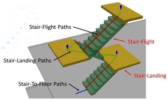
Figure 2.
Stair-associated paths suggested by i-GIT [1].
The original version of the i-GIT algorithm was very complicated during the generation of stair flight paths, and it also has limitations on the stair model that it can apply to. For example, it requires the stair run to end with a riser, and a physical riser is not allowed. Moreover, the face on the riser cannot be slanted, and tread nosing is not allowed [1]. However, most indoor stairs have physical treads with nosing and slanted risers. This has greatly reduced the efficiency of the automatic generation of indoor paths. Those modeling limitations restrict the algorithm’s applicability and require modelers’ extra efforts to adjust models to yield to the algorithm. Therefore, the algorithm has undergone a major revision [33], which overcame the aforementioned modeling limitations with more concise logic. The new algorithm for generating a stair flight path is as follows [33]:
- Step 1:
- Generate the “minimal bounding volume” of the stair flight, as shown in the gray box of Figure 3. Thereafter, extract the top and bottom surfaces of this bounding volume, extract all sides of these surfaces, and then generate the midpoints of each side, as shown by the blue points (top surface) and purple points (bottom surface) in Figure 3;
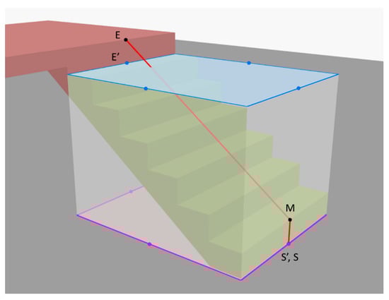 Figure 3. Illustration of stair flight path generation logic in the 2nd version of the intelligent generation of indoor topology (i-GIT) algorithm [33].
 - Step 2:
- Determine the candidates for the start and end of the stair path (as shown by S′ and E′ in Figure 3) by performing a 3D intersection on the eight midpoints in Step 1 with the stair flight;
- Step 3:
- Create the path end (as shown by E in Figure 3) by searching the nearest landing or slab to Point E′, obtained in Step 2, and adjusting the elevation of Point E′ as high as the selected landing or slab. Point E is the endpoint of the stair flight path;
- Step 4:
- Create the path start (as shown by S in Figure 3) by searching the nearest landing or slab to Point S′ obtained in Step 2 and adjusting the elevation of Point S′ as high as the selected landing or slab. Point S then is the starting point of the stair flight path;
- Step 5:
- Create the waypoint of the run path (as shown by M in Figure 3) by lifting up the elevation of Point S obtained in Step 4 by one step height. Point M then is the waypoint of the stair flight path;
- Step 6:
- Generate the stair flight path by linking up the start point (S), waypoint (M), and endpoint (E) obtained in Step 3–Step 5. The resulting segments are the stair flight path, as shown by the red polyline of Figure 3.
Although the current version of the i-GIT algorithm eliminates the limitations of the original algorithm on stair modeling parameters, as well as improves the efficiency of the algorithm, it is only applicable to straight stairs, and does not support the spiral and winder stairs that are commonly seen in town houses or public buildings. These two types of stairs do not have landings. The steps of both stairs may change their direction with height. The step shape and size of winder stairs will not even remain identical. These features of stair structure increase the difficulty of designing an algorithm to support the two types of stairs. The aim of this study is to overcome these difficulties and develop an algorithm that can support spiral and winder stairs while remaining applicable to straight stairs, as originally supported by the i-GIT algorithm.
3. Requirements and Considerations
A complete staircase is composed of runs, landings, supports, and railings. Of these, the components that related to path generation are runs and landings. A run is composed of several steps and the steps can be paved with treads and risers. According to the orientation of the run, stairs can be roughly divided into three types: straight, spiral, and winder. Moreover, the support of runs can be monolithic and non-monolithic. The monolithic runs can, furthermore, be smooth, stepped, and horizontal bottom.
The aforementioned types and structures of stairs directly influence the design of a stair flight path generation algorithm. This section first describes the types of stairs, the variations in stair structure, and important modeling parameters that should be taken into account by the algorithm, namely the run orientation, run structure, treads, risers, etc.
3.1. Run Orientation
The algorithm should support three orientations of stairs: straight (as shown in Figure 4a), spiral (as shown in Figure 4b), and winder stairs. Winders can be L-shaped (as shown in Figure 4c) or U-shaped (as shown in Figure 4d). Straight stairs have straight runs connected by a landing in between, whereas spiral and winder runs usually have no landing and are directly connected to the slabs. Moreover, the steps of these two types of stairs will change their orientation with height. Furthermore, the steps of a winder staircase do not have a consistent shape and size like the steps of straight and spiral stairs. In L-shaped winder stairs, steps at the turning of a run are winders, which differ in shape and size from other steps. This feature has the advantage of saving the floor area required, and thus they are commonly seen the town houses. On the other hand, spiral stairs and U-shaped winder stairs are commonly seen in public buildings, such as schools, libraries, and government agencies.
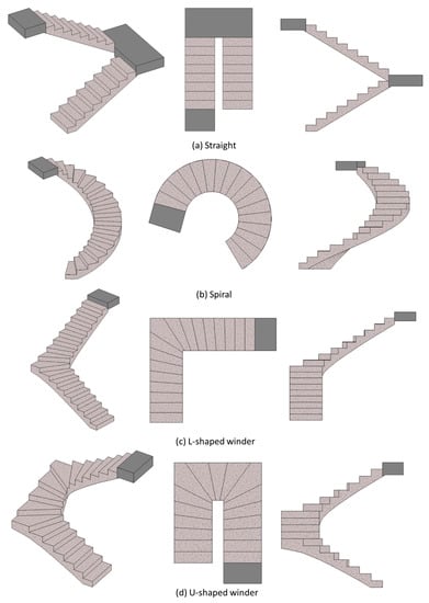
Figure 4.
Categories of stair run orientations.
3.2. Run Structure
The algorithm should support monolithic and non-monolithic runs. As shown in Figure 5, monolithic runs have a solid support structure under their treads, and the material is usually concrete. Cast-in-place or precast stairs often fall into this category. The algorithm should support all variations in the support structure for monolithic runs, such as stepped (as shown in Figure 5a), smooth (as shown in Figure 5b), and horizontal bottoms (as shown in Figure 5c).
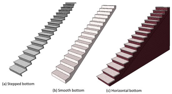
Figure 5.
Monolithic stairs.
In contrast, non-monolithic runs do not have the aforementioned support structure underneath their treads, but the treads are supported by a stringer or carriage. Non-monolithic runs are usually seen in assembled stairs. Figure 6 shows non-monolithic runs for the three orientations of stairs.
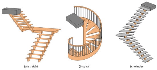
Figure 6.
Non-monolithic stairs.
3.3. Treads
The algorithm should support steps without treads (as shown in Figure 7a) and with treads (as shown in Figure 7b–e). The steps with treads can be without nosing (as shown in Figure 7b) or with nosing (as shown in Figure 7c–e). The algorithm should support steps with nosing whose profile is flat, pan, or circular, as shown in Figure 7c–e, respectively.
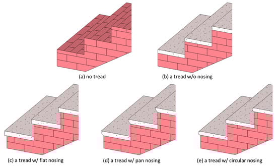
Figure 7.
Treads with various nosing profiles.
3.4. Risers
The algorithm should support runs without risers (as shown in Figure 8a) and runs with risers (as shown in Figure 8b). Moreover, the vertical parts of the steps can be upright (as shown in Figure 8a1,b1) or slanted (as shown in Figure 8a2,b2).
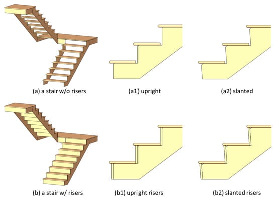
Figure 8.
Stairs with risers.
The algorithm also needs to support different modeling approaches to end a run. Common runs begin with a riser and end with a riser, as shown in Figure 9a. For this type of run, the bottom of the first step (lowest step) will touch the slab, while the last step (highest step) usually contains a riser without a physical step. For those runs without risers, the last step appears to be missing. In contrast, if a run ends with a tread as shown in Figure 9b, then the last step (highest step) of the run will have a physical step, and the elevation of its top surface will be identical to the elevation of connected landing or slab.
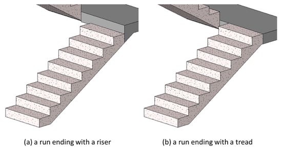
Figure 9.
Stair runs ending with (a) a riser or (b) a tread.
Table 1 compares the variations in stair structures supported by two versions of i-GIT algorithms and the one proposed by this study. According to Table 1, the proposed algorithm greatly improves the applicability to support different stair types and modeling parameters.

Table 1.
Comparisons of how each algorithm supports different stair run orientations and modeling parameters.
4. Implementation
4.1. Overview and Notation
The indoor space model used for the stair paths generated in this study is a navigation graph, also known as a centerline-based model, which is a symbolic-based approach, as mentioned in the literature review. The stair paths generated and discussed here are mainly the stair flight paths as suggested by i-GIT, as shown in Figure 2 [1]. Figure 10 shows the stair paths and notations for three stairs with different run orientations, where red lines are the stair flight paths and blue lines are stair–landing paths. Each stair flight path includes a start, an end, and several waypoints. A path start is the vertical projection point of the front-edge midpoint of the first step’s tread on the slab (or stair landing) below, as shown by Point S in Figure 10. A path end is the vertical projection point of the rear-edge midpoint of the last step’s tread on the slab (or stair landing) above, as shown by Point E in Figure 10. Waypoints are the midpoints of the front-edge of the tread on each step between the path start and end. The stair flight path is the polyline connecting the path start, waypoints in order, and path end, as shown by the red lines in Figure 10. There is only one waypoint in the flight path for straight stairs, while there are multiple waypoints for spiral and winder stairs.
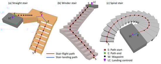
Figure 10.
Overview and notations for a stair path.
In summary, the process for generating a stair flight path is to determine the path start, waypoints, and path end of each flight, and then connect these nodes in order to form a polyline, which is the stair flight path. Figure 11 shows the overall process for generating a stair flight path for a single run. There are four major procedures as follows: (1) GetPathStartZValue—to calculate the elevation or Z value of the path start; (2) GeneratePathStart—to determine and generate the path start; (3) GeneratePathWaypoints—to determine and generate the waypoints; and (4) GeneratePathEnd—to determine and generate the path end. Connecting those nodes in order can form the path. The IFC building model elements required by the algorithm only include IFCSTAIRFLIGHT and IFCSLAB. The former contains all stair flights, while the latter contains both slabs and stair landings.
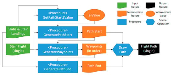
Figure 11.
Flowchart for generating a stair flight path.
4.2. Algorithm Logic
This section takes the spiral stair in Figure 10c as an example to describe the algorithmic logic of the four procedures.
4.2.1. GetPathStartZValue
The first procedure for generating a stair flight path is to determine the elevation or Z-value of the path start. This value will be combined with the riser height and used in the following procedures to generate the path start, waypoints, and path end of the path.
According to the definition of a path start in Section 4.1, the elevation of a path start should be the maximal Z-value of the slab or stair landing connected to the bottom of the run. GIS and BIM software have a built-in function that can directly obtain the minimal or maximal Z-values of a 3D object. Therefore, to determine the elevation of a path start, one only needs to determine the slab or stair landing connected to the bottom of the stair run, then retrieve its maximal Z-value. However, for those stair runs without physical risers, as shown in the run of Figure 8a, one cannot find the required slab or stair landing by simply applying a 3D intersection on IFCSTAIRFLIGHT and IFCSLAB.
The method used in this study is as follows: first, we generate the bottom footprint of a stair run, as shown by the yellow polygon in Figure 12, and then use a distance slightly greater than the step height (e.g., 30 cm) as the searching tolerance to perform a spatial search targeted with the footprint against all the features in IFCSLAB. The maximal Z-value of the feature found is the correct elevation of a path start.
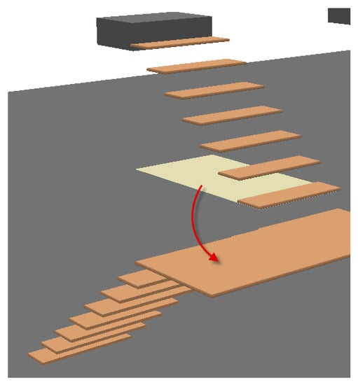
Figure 12.
Illustration of the method for searching for the connecting slab or stair landing of a stair flight.
4.2.2. GeneratePathStart and GeneratePathWaypoints
After obtaining the Z-value of the path start, the algorithm begins to generate the path start, waypoints, and path end of the path. However, the first generated node is not the path start; instead, the waypoint at the first step of the run, as shown by the W1 in Figure 13, is the path start. This consideration is for those stair runs without physical risers whose path starts have to be determined by their first step. The method of identifying W1 is first to generate the footprint of the run (as shown by the orange polygon in Figure 13), and lift the elevation of this footprint to the top of the first step, i.e., adding the height of a riser to the Z-value of the path start obtained in Section 4.2.1. The elevated footprint is shown by the cyan polygon in Figure 13. Subsequently, performing the intersection on this footprint with the stair run can yield the bounding area ABCD. Next, the front edge of the first step, i.e., , is then extracted through an appropriate method, which will be addressed later. Then, the middle point of is the waypoint W1. Lastly, by lowering the elevation of waypoint W1 to the Z-value of the path start, the resulting point is the path start.
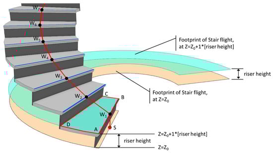
Figure 13.
Illustration of the method for determining the path start and waypoints.
The method for identifying the front edge of the first step, , is as follows: First, make an inner buffer by 5 cm on the elevated run footprint whose Z-value is equal to the top of the first step (as shown by the cyan block in Figure 13, resulting in the blue polygon in Figure 14. Next, extract all sides of the bounding area ABDC obtained in the previous step, i.e., , , , and , then the front edge of the first step, , is the side that does not touch the shrunken footprint (the blue polygon in Figure 14).
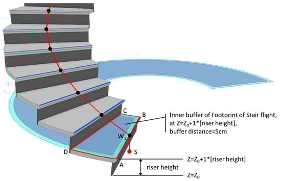
Figure 14.
Illustration of the method for determining the front edge () of the first step.
The remaining waypoints can then be generated by a method similar to that of obtaining the waypoint W1 of the first step. Taking the waypoint of the second step, W2, as an example, first lift the run footprint to the top of the second step, and perform the intersection on this elevated footprint with the stair run to yield the bounding area. Next, extract all sides of the bounding area and select the two sides with the longest and second longest lengths. At last, select the one that is the closest to the waypoint W1; the midpoint of that side is the waypoint W2 of the second step. The methods for generating the remaining waypoints can be deduced via this analogy.
4.2.3. GeneratePathEnd
During the generation of waypoints for the last step, the midpoint of the rear edge of the last step (as shown by E′ in Figure 15) is also extracted in order to generate the path end. Search the slab or stair landing with a distance of approximately one step height from E′ (e.g., 30 cm), and lift the elevation of E′ to the maximal Z-value of the found slab or stair landing. The resulting point (as shown by E in Figure 15) is then the path end.
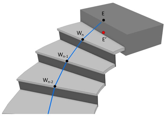
Figure 15.
Illustration of the method for determining the path end.
5. Verification
5.1. Test Cases
This study used 57 stairs as test cases, as shown in Figure 16, including three self-built stairs, where E4 and E5 are winder stairs and E6 is a precast stair. The remaining 54 stairs were downloaded from the official website of Autodesk Revit [37]. Cases of type A, type B, and type E were created by components while cases of type C, type D, and type F were created by sketching. In all test cases, straight stairs with a single run (A1–A12, C1–C12) and straight stairs with two runs (including a landing) (B1–B10, D1–D10) are supported by the current version of the i-GIT algorithm, accounting for a total of 44 cases. The target types of stairs to be supported by this study include spiral stairs with no risers (B11, B12, D11, D12), spiral stairs with risers (E1–E3, F1–F3), L-shaped winder stairs (E4), U-shaped winder stairs (E5), and precast stairs (E6), accounting for a total of 13 cases.
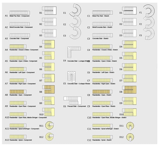
Figure 16.
The test cases chosen to verify the proposed algorithm.
This study exported all test cases to the IFC 2x3 using the built-in IFC Export tool provided by Autodesk Revit 2019, and found that cases C1 and C4–C7 were converted to IFCSTAIR elements, whereas the remaining stairs were in IFCSTAIRFLIGHT. The differences between elements IFCSTAIR and IFCSTAIRFLIGHT are that the runs and landings of the former are not physically separated as well, as they do not provide attributes of the runs, such as number of risers, number of trends, riser height, and trend length. Since requiring both the geometric information of the stair structure and the attributes of the number of risers and riser height, the algorithm is not applicable to cases C1 and C4–C7. Besides, cases D2 and D3 were converted to IFCSTAIRFLIGHT elements, but their runs are not correctly separated from the landing, and the attributes of the runs are also incorrect. The algorithm cannot process these two cases, either. The original models of all seven flawed cases happened to all be created by sketching. This coincidence remained suspicious and needs to be further investigated in future study.
The study excluded the aforementioned seven stairs, and used the remaining 50 cases for the test. According to the classification mentioned in Section 3, these 50 cases can be divided into 13 different groups, as shown in Table 2.
Table 2.
Combinations of run orientations and modeling parameters among the test cases.
5.2. Test Results
The test results of path generation on 50 cases are shown in Figure 17. Table 3 summarizes the results. As indicated by Table 3, among 50 test stairs, there is only one case (denoted as D1) whose generated path appears to be deviated. In the other eight cases (denoted as D4–D10 and E6), some of their waypoints are missing, but the geometric correctness of the paths is unaffected.
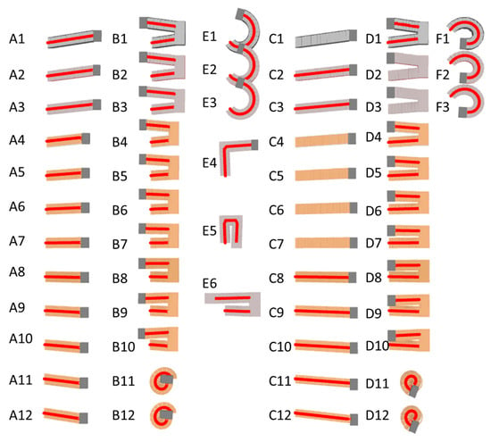
Figure 17.
A summary of test results.
Table 3.
Summary of test results.
Figure 18, Figure 19 and Figure 20 show the test results of three representative cases among each of 13 test groups, including the aforementioned erroneous cases. Test case D1 belongs to a non-monolithic stair with two straight runs structured by pan-shaped nosing treads and slanted risers. According to test case D1 shown in Figure 18, the path generated for the first run is completely correct, whereas the path for the second run has a correct path start, but its waypoints on the second and seventh steps are missing, as well as the positions for the waypoints on the third and eighth steps, and the path end is incorrect. Since other cases in the same test group as case D1, such as A1 and B1, do not have these errors, it could be inferred that the errors may result from the modeling method of the original model, where case D1 is modeled by sketching in Revit, whereas other cases are modeled by stair components. When modeling a stair by sketching in Revit, the modelers allocate all the risers by manually drawing the front edges of the step on a 2D plan. Under normal circumstances, the spacing between these risers should be equidistant (indicating that the step depths for all steps are identical), ensuring the stair is geometrically correct. Even a slight deviation in some spacing between risers may result in the errors found in test case D1. However, further investigation is still needed to prove this inference.
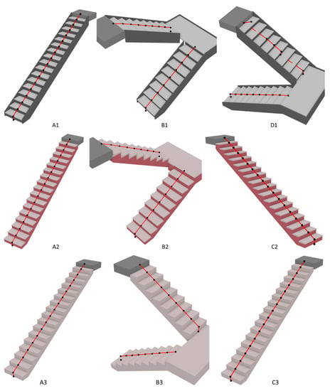
Figure 18.
The test results for Groups 1–3.
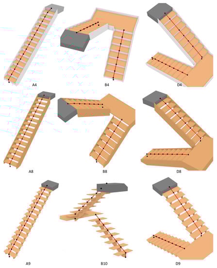
Figure 19.
The test results for Groups 4–6.
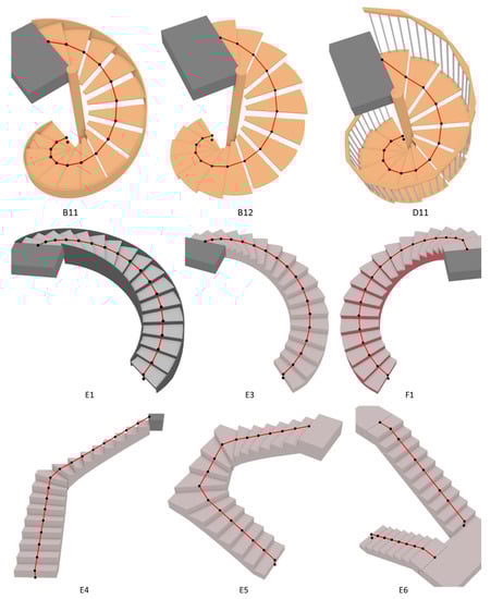
Figure 20.
The test results for Groups 7–13.
According to the test results shown in Figure 19, in the test cases of D4–D10, the waypoints on the second and seventh steps of the second run are missing, but the geometric correctness of the path remains unaffected. Since the original model of these cases were also created by sketching in Revit, they may also suffer from similar problems to test case D1. Since the positions of waypoints on the third and eighth steps in these cases are correct, the geometric correctness of paths are therefore not affected.
The last erroneous case, E6, is a precast stair whose runs end with a tread, so the path segment on the last step appears horizontal. As shown in Figure 20, in test case E6, the waypoints on the second, fifth, and eighth steps of the second run are missing, but the geometric correctness of the path is not affected. Since the original model of test case E1 is created by stair components in Revit, the issue found in this case remains unsolved and needs to be further explored in the future.
All in all, excluding the seven cases with incorrect exported IFC data, the test results show that the correctness rate of stair paths generated by this algorithm is up to 98% (49/50). If those cases where some waypoints are missing but geometric correctness of paths remains unaffected are taken into consideration, the overall correctness rate of the stair paths is 82% (41/50).
6. Conclusions
Indoor location-based services are becoming more and more popular. Many applications such as wayfinding, resource management, and emergency response need to rely on accurate spatial data models. Based on the IFC model and the indoor topology generation framework suggested by i-GIT, this study developed a stair flight path generation algorithm that can support straight stairs, spiral stairs, and winder stairs with variations in modeling parameters during 3D modeling in BIM software. Test results showed the following: (1) among the 57 test cases, there were seven stairs constructed in Revit by sketching the staircase boundaries that did not correctly provide the geometry and attribute information required by the algorithm after conversion to the IFC format. The algorithm was, thus, unable to process these stairs and generate the paths. (2) Among the remaining 50 test cases, there was only one case whose path appeared to be incorrect. In the other eight test cases, although there were several waypoints missing, the geometric correctness of the paths remained unaffected.
The issue found in seven cases may have arisen from the modeling method used during 3D modeling in Revit or merely malfunction of the built-in function IFC Export provided by Revit; more testing and comparison of these problematic cases is required in the future. The issue found in the remaining 50 cases may have arisen from insufficient accuracy in stair geometry caused by the modeling method since the algorithm relies on the riser height and the number of risers provided by the stair model. If the geometric data of runs are not precisely presented, the algorithm generating path start, end, and waypoints may fail to function on certain steps, causing some waypoints to be missing or even path deviation. In the future, the algorithm may consider adding a tolerance when performing spatial search or 3D intersection, so as to prevent the aforementioned issues from hindering the correct generation of the path.
Moreover, in order to support spiral and winder stairs, the algorithm has to generate all waypoints on every step, so the computation time was much longer than that of the current i-GIT algorithm. It is suggested that the algorithm developed in this study can be integrated with the i-GIT algorithm in the future. In future work, a predetermination on stair orientation can be added before processing all stair models. For stairs with straight runs, the current i-GIT algorithm should be used, whereas for stairs with non-straight runs, the algorithm developed in this study should be used instead.
Funding
This research was funded by the Ministry of Science and Technology, Taiwan, R. O. C., under grant MOST 108-2221-E-035-012.
Acknowledgments
I would like to thank Uni-edit (www.uni-edit.net) for editing and proofreading this manuscript.
Conflicts of Interest
The author declares no conflict of interest. The funder had no role in the design of the study; in the collection, analyses, or interpretation of data; in the writing of the manuscript, or in the decision to publish the results.
References
- Lin, W.Y.; Lin, P.H. Intelligent generation of indoor topology (i-GIT) for human indoor pathfinding based on IFC models and 3D GIS technology. Autom. Constr. 2018, 94, 340–359. [Google Scholar] [CrossRef]
- Zlatanova, S.; Liu, L.; Sithole, G.; Zhao, J.; Mortari, F. Space Subdivision for indoor Applications; Delft University of Technology, OTB Research Institute for the Built Environment: Delft, The Netherlands, 2014. [Google Scholar]
- Gunduz, M.; Isikdag, U.; Basaraner, M. A Review of recent research in indoor modelling & mapping. ISPRS Int. Arch. Photogramm. Remote. Sens. Spat. Inf. Sci. 2016, 41, 289–294. [Google Scholar]
- Worboys, M.; Walton, L. Towards A Model of Indoor Space; University of Maine: Orono, ME, USA, 2008. [Google Scholar]
- Ma, Z.; Ren, Y. Integrated Application of BIM and GIS: An Overview. Procedia Eng. 2017, 196, 1072–1079. [Google Scholar] [CrossRef]
- Yan, W.; Culp, C.; Graf, R. Integrating BIM and gaming for real-time interactive architectural visualization. Autom. Constr. 2011, 20, 446–458. [Google Scholar] [CrossRef]
- Lin, Y.-H.; Liu, Y.-S.; Gao, G.; Han, X.-G.; Lai, C.-Y.; Gu, M. The IFC-based path planning for 3D indoor spaces. Adv. Eng. Inform. 2013, 27, 189–205. [Google Scholar] [CrossRef]
- Zhu, Q.; Li, Y.; Xiong, Q.; Zlatanova, S.; Ding, Y.; Zhang, Y.; Zhou, Y. Indoor Multi-Dimensional Location GML and Its Application for Ubiquitous Indoor Location Services. ISPRS Int. J. Geo-Inf. 2016, 5, 220. [Google Scholar] [CrossRef]
- Xu, M.; Wei, S.; Zlatanova, S.; Zhang, R. BIM-Based indoor path planning considering obstacles. Isprs Ann. Photogramm. Remote. Sens. Spat. Inf. Sci. 2017, 417–423. [Google Scholar] [CrossRef]
- Hijazi, I.; Ehlers, M.; Zlatanova, S. BIM for geo-analysis (BIM4GEOA): Set up of 3D information system with open source software and open specification (OS). In Proceedings of the 5th International 3D GeoInfo Conference, Berlin, Germany, 3–4 November 2010. [Google Scholar]
- Lee, J. A Three-Dimensional Navigable Data Model to Support Emergency Response in Microspatial Built-Environments. Ann. Assoc. Am. Geogr. 2007, 97, 512–529. [Google Scholar] [CrossRef]
- Tashakkori, H.; Rajabifard, A.; Kalantari, M. A new 3D indoor/outdoor spatial model for indoor emergency response facilitation. Build. Environ. 2015, 89, 170–182. [Google Scholar] [CrossRef]
- Xiong, Q.; Zhu, Q.; Du, Z.; Zhu, X.; Zhang, Y.; Niu, L.; Li, Y.; Zhou, Y. A Dynamic Indoor Field Model for Emergency Evacuation Simulation. ISPRS Int. J. Geo-Inf. 2017, 6, 104. [Google Scholar] [CrossRef]
- Afyouni, I.; Ray, C.; Claramunt, C. Spatial models for context-aware indoor navigation systems: A survey. J. Spat. Inf. Sci. 2012, 4, 85–123. [Google Scholar] [CrossRef]
- Zlatanova, S.; Sithole, G.; Nakagawa, M.; Zhu, Q. Problems In Indoor Mapping and Modelling. ISPRS Int. Arch. Photogramm. Remote. Sens. Spat. Inf. Sci. 2013, 4, 63–68. [Google Scholar] [CrossRef]
- Becker, T.; Nagel, C.; Kolbe, T.H. A Multilayered Space-Event Model for Navigation in Indoor Spaces; Springer: Berlin/Heidelberg, Germany, 2008; pp. 61–77. [Google Scholar]
- Teo, T.-A.; Cho, K.-H. BIM-oriented indoor network model for indoor and outdoor combined route planning. Adv. Eng. Informatics 2016, 30, 268–282. [Google Scholar] [CrossRef]
- Liu, L.; Zlatanova, S. Towards a 3D network model for indoor navigation. In Urban and Regional Data Management; CRC Press: Delft, The Netherlands, 2011; pp. 79–94. [Google Scholar]
- Isikdag, U.; Zlatanova, S.; Underwood, J. A BIM-Oriented Model for supporting indoor navigation requirements. Comput. Environ. Urban Syst. 2013, 41, 112–123. [Google Scholar] [CrossRef]
- Diakite, A.A.; Zlatanova, S. Spatial subdivision of complex indoor environments for 3D indoor navigation. Int. J. Geogr. Inf. Sci. 2017, 32, 213–235. [Google Scholar] [CrossRef]
- Park, S.; Yu, K.; Kim, J. Data Model for IndoorGML Extension to Support Indoor Navigation of People with Mobility Disabilities. ISPRS Int. J. Geo-Inf. 2020, 9, 66. [Google Scholar] [CrossRef]
- Taneja, S.; Akinci, B.; Garrett, J.H.; Soibelman, L. Algorithms for automated generation of navigation models from building information models to support indoor map-matching. Autom. Constr. 2016, 61, 24–41. [Google Scholar] [CrossRef]
- Yang, L.; Worboys, M. Generation of navigation graphs for indoor space. Int. J. Geogr. Inf. Sci. 2015, 29, 1–20. [Google Scholar] [CrossRef]
- Tang, S.J.; Zhu, Q.; Wang, W.W.; Zhang, Y.T. automatic topology derivation from ifc building model for IN-door Intelligent navigation. ISPRS Int. Arch. Photogramm. Remote. Sens. Spat. Inf. Sci. 2015, 7–11. [Google Scholar] [CrossRef]
- Lewandowicz, E.; Lisowski, P.; Flisek, P. A Modified Methodology for Generating Indoor Navigation Models. ISPRS Int. J. Geo-Inf. 2019, 8, 60. [Google Scholar] [CrossRef]
- Lin, W.Y.; Lin, P.-H.; Tserng, H. Automating the Generation of Indoor Space Topology for 3D Route Planning Using BIM and 3D-GIS Techniques. In Proceedings of the 34th International Symposium on Automation and Robotics in Construction, Taipei, Taiwan, 28 June–1 July 2017; pp. 437–444. [Google Scholar]
- Zheng, X.Z.; Tian, D.; Zhang, M.; Hu, C.; Tong, L. A Stairs Evacuation Model Considering the Pedestrian Merging Flows. Discret. Dyn. Nat. Soc. 2019, 2019, 1–11. [Google Scholar] [CrossRef]
- Thill, J.-C.; Dao, T.H.D.; Zhou, Y. Traveling in the three-dimensional city: Applications in route planning, accessibility assessment, location analysis and beyond. J. Transp. Geogr. 2011, 19, 405–421. [Google Scholar] [CrossRef]
- Roh, S.; Aziz, Z.; Pena-Mora, F.A. An object-based 3D walk-through model for interior construction progress monitoring. Autom. Constr. 2011, 20, 66–75. [Google Scholar] [CrossRef]
- Sano, T.; Yajima, M.; Kadokura, H.; Sekizawa, A. Human behavior in a staircase during a total evacuation drill in a high-rise building. Fire Mater. 2016, 41, 375–386. [Google Scholar] [CrossRef]
- Köster, G.; Lehmberg, D.; Kneidl, A. Walking on stairs: Experiment and model. Phys. Rev. E 2019, 100, 022310. [Google Scholar] [CrossRef] [PubMed]
- Tsiliakou, E.; Dimopoulou, E. 3D Network Analysis for Indoor Space Applications. ISPRS Int. Arch. Photogramm. Remote. Sens. Spat. Inf. Sci. 2016, 2, 147–154. [Google Scholar] [CrossRef]
- Lin, W.Y. The generation of an indoor network with non-level paths based on IFC-models and its practical applications. J. Chin. Inst. Civil Hydraul. Eng. 2019, 31, 153–162. [Google Scholar] [CrossRef]
- Wang, Y.Q.; Lin, W.Y. An extension of intelligent generation of indoor topology (i-GIT) for non-level paths associated with ramps and elevators. In Proceedings of the 22nd Symposium on Construction Engineering and Management, Taipei, Taiwan, 6 July 2018. [Google Scholar]
- Kang, T.W.; Hong, C.H. A study on software architecture for effective BIM/GIS-based facility management data integration. Autom. Constr. 2015, 54, 25–38. [Google Scholar] [CrossRef]
- Galea, E.R.; Sharp, G.; Lawrence, P. Investigating the Representation of Merging Behavior at the Floor--Stair Interface in Computer Simulations of Multi-Floor Building Evacuations. J. Fire Prot. Eng. 2008, 18, 291–316. [Google Scholar] [CrossRef]
- Revit Sample Stair and Railing Files. Available online: http://revit.downloads.autodesk.com/download/2019RVT_RTM/Docs/InProd/Stair_Samples.rvt (accessed on 23 December 2019).


© 2020 by the author. Licensee MDPI, Basel, Switzerland. This article is an open access article distributed under the terms and conditions of the Creative Commons Attribution (CC BY) license (http://creativecommons.org/licenses/by/4.0/).