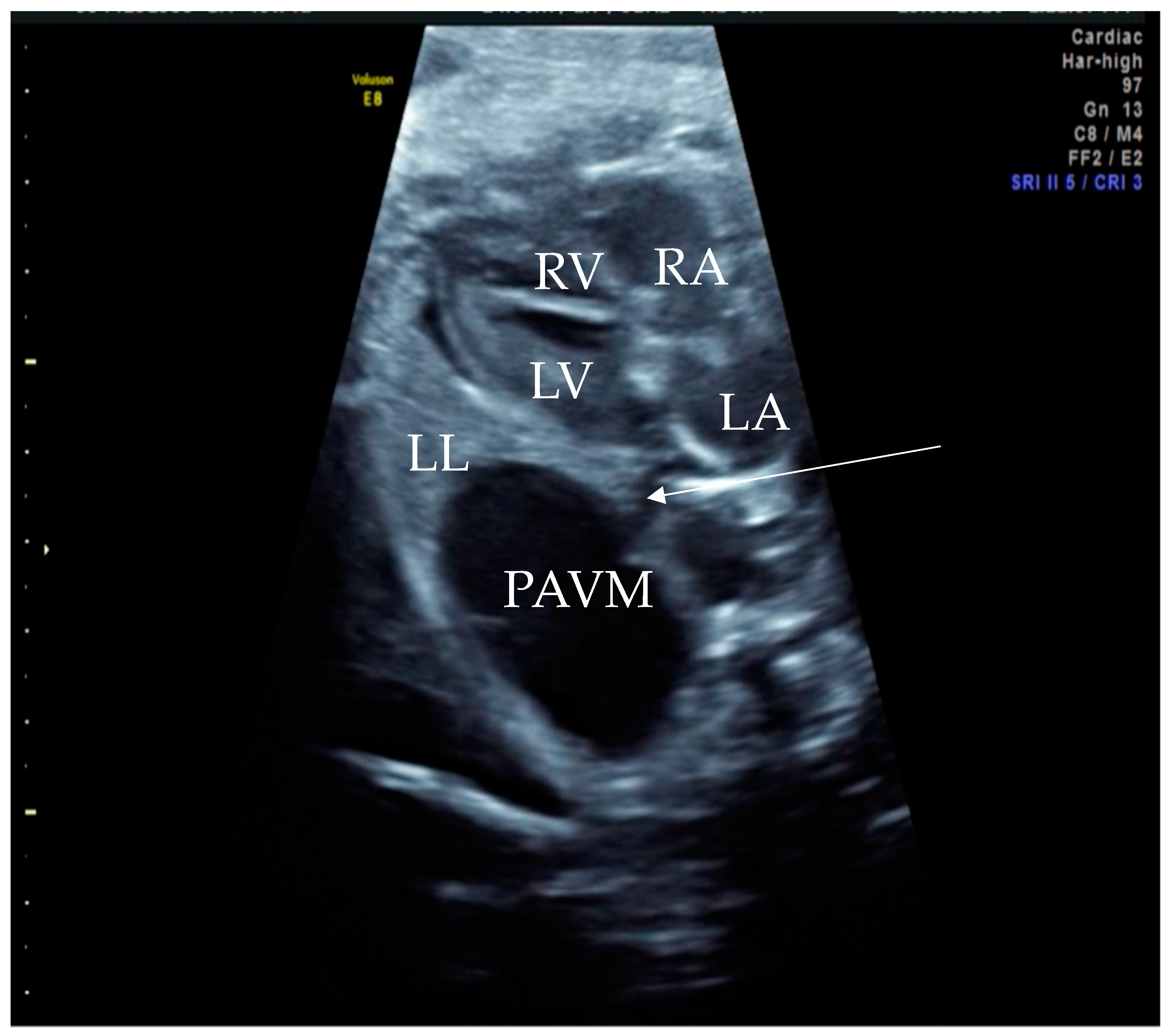
Figure 1.
Prenatal B-Mode transabdominal ultrasound picture with cystic structure on the level of four chamber view with a clear linkage of the structure to the left atrium. RV—right ventricle, LV—left ventricle, RA—right atrium, LA—left atrium, LL—left lung, PAVM—pulmonary arteriovenous malformation, arrow—showing the connecting vessel to the left atrium and the PAVM. Actually, this finding led to the suspicion of PAVM. We needed to prove it with color Doppler, as shown in the next picture.
Figure 2.
Prenatal transabdominal color Doppler mode ultrasound picture with visible bidirectional flow in the cystic structure. Arrow 1—venous part of the feeding vessels with connection to the left atrium, Arrow 2—arterial part of the connection to the left main branch of the pulmonal artery, RV—right ventricle, LV—left ventricle, RA—right atrium, LA—left atrium, and PAVM—pulmonary arteriovenous malformation. Due to the gestational age, it was difficult to distinguish the two feeding vessels in one picture, as shown in the last prenatal picture (
Figure 3).
Figure 3.
Prenatal B-Mode transabdominal ultrasound picture of the PAVM with a clear linkage of the structure to the left atrium and a visible second vessel, more dorsal and cranial, appearing to be the arterial part of the feeding vessels connecting to the left main branch of the pulmonary artery. RV—right ventricle, LV—left ventricle, RA—right atrium, LA—left atrium, LL—left lung, PAVM—pulmonary arteriovenous malformation, arrow 1—showing the venous vessel connecting the left atrium and the PAVM, and arrow 2—showing the arterial vessel connecting the PAVM.
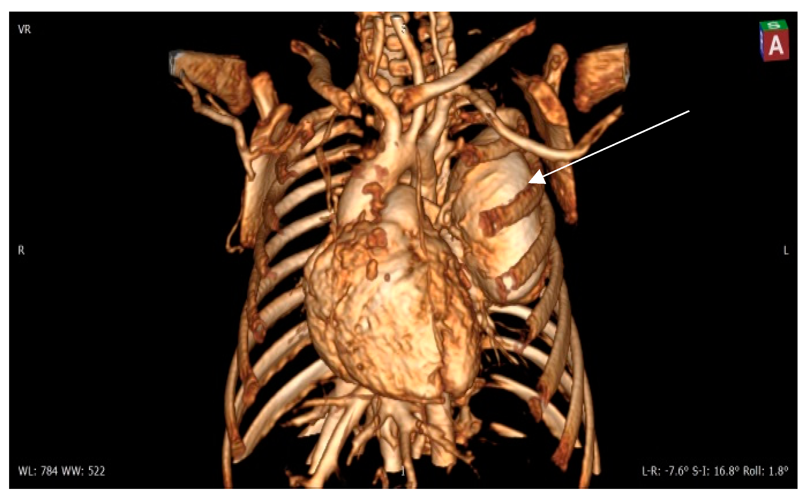
Figure 4.
Contrast 3D-CT reconstruction of the structure in the left lung—arrow directed to the PAVM. A rounded formation is present in the left lung constituting the “external manifestation” of the arteriovenous fistula.
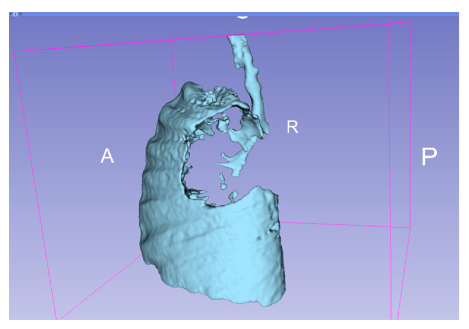
Figure 5.
3D representation of the affected areas of the lung. A—anterior, P—posterior, R—right.
Figure 6.
Contrast CT—native image of the branches of the pulmonary artery for three lower and two upper segments. Preoperative diagnostics focus on 3D-CT reconstruction and detailing of the anatomical variations of all arterial and venous vessels, as evident from our case. Contrast CT (
Figure 4,
Figure 5 and
Figure 6) shows communication between the left lower branch of the pulmonary artery—an aneurysmal formation—arrow 1 in
Figure 6, measuring 35 × 30 × 25 mm, and drainage into a wide vessel with an irregular shape and through the left inferior pulmonary vein—arrow 2 in
Figure 6 into the left atrium—arrow 3 in
Figure 6 (independent branching of the subsegmental branches of the LPA for three lower segments and two upper). The inlet and outlet vessels of the AV malformation are shown. The bronchography shows a lack of lung structures in the location of the aneurysmal formation. There are also no signs of pressure and/or hypoplasia in the rest of the left lung.


