Abstract
In this contribution, a method based on a solid solution theory of clathrate hydrate for multiple cage occupancy, host lattice relaxation, and guest-guest interactions is presented to estimate hydrate formation conditions of binary and ternary gas mixtures. We performed molecular modeling of the structure, guest distribution, and hydrate formation conditions for the CO2 + CH4 and CO2 + CH4 + N2 gas hydrates. In all considered systems with and without N2, at high and medium content of CO2 in the gas phase, we found that CO2 was more favorable in occupying clathrate hydrate cavities than CH4 or N2. The addition of N2 to the gas phase increased the ratio concentration of CO2 in comparison with the concentration of CH4 in clathrate hydrates and made gas replacement more effective. The mole fraction of CO2 in the CO2 + CH4 + N2 gas hydrate rapidly increased with the growth of its content in the gas phase, and the formation pressure of the CO2 + CH4 + N2 gas hydrate rose in comparison to the formation pressure of the CO2 + CH4 gas hydrate. The obtained results agreed with the known experimental data for simple CH4 and CO2 gas hydrates and the mixed CO2 + CH4 gas hydrate.
1. Introduction
Due to concerns of an increasing global warming effect, the capture from industrial flue gas and long-term storage of carbon dioxide are among the most important challenges facing the world scientific community today.
Various strategies [1] to sequester carbon dioxide have been proposed, but a technology for large-scale and safely stored CO2 has not been completely developed.
Currently, the leading approach to this problem involves the injection of CO2 into depleted deep underground natural gas reservoirs [2]. In seismically active zones such as Japan, the use of this method of CO2 storage may lead to gas leakage due to geological perturbations such as earthquakes or fractures. Another approach offered by Ohgaki and Inoue [3] is the sequestration of CO2 as solid hydrates through the formation of CO2 clathrate hydrate. Recently, the injection of CO2 into porous sediments at a depth of several hundred meters below the deep ocean floor has been proposed as an alternative long-term sequestration option that would be resistant to geophysical perturbations [4]. Such deposition of CO2 prevents the transport of the CO2 back to the surface due to the formation of a CO2 clathrate hydrate capping layer that reduces the migration. The authors estimate this storage strategy could remain intact for millions of years. It has also been shown that CO2 hydrates have anomalously low dissociation rates at atmospheric pressure. This self-preservation effect takes place in the temperature range 245–271 K, which could be significant in practice for the CO2 storage in the form of clathrate hydrates [5].
Clathrate hydrates are nonstoichiometric inclusion compounds consisting of water (host) molecules forming a crystalline framework in which cavities (cages) guest molecules can be included. In nature, three types of gas hydrates are common: Hydrates of cubic structure (CS)-I, cubic structure CS-II, and hexagonal structure (HS)-III [6]. The hydrate structure is determined primarily by the size of guest molecules. Thus, large guest molecules such as propane and isobutane as well as small guests, in particular oxygen, nitrogen, and hydrogen, form the cubic structure CS-II. Guest molecules of intermediate size such as methane, xenon, and carbon dioxide form hydrates of the cubic structure CS-I. The presence of two types of guest molecules is necessary to form the hexagonal structure HS-III: A very large molecule (e.g., 2,2-dimethylbutane) and a small molecule (e.g., methane). The hydrate structures differ by size and number of cavities in their unit cells.
Large amounts of natural gas hydrates are composed mainly of methane in the form of solid hydrates stored on continental margins and in permafrost regions [6]. Technologies involving the simultaneous production of raw hydrocarbon and greenhouse-gas sequestration is promising. Carbon dioxide sequestration in deep-sea sediments or permafrost regions can be performed simultaneously with natural gas recovery by swapping hydrocarbon molecules in hydrate cages for carbon dioxide molecules, thus providing a mechanism of hydrocarbons production and greenhouse gas sequestration [7,8,9]. The replacement of CH4 hydrates by CO2 hydrates has been studied [7] for recovering CH4 gas. When a mixture of water with gas or liquid CO2 itself is put under certain pressure, a solid CO2 hydrate can be formed at much milder P-T conditions than a CH4 hydrate can [10]. Thus, the swapping process between two gaseous guests is considered to be a promising approach to long-term storage of CO2. When the CH4 hydrate is put under a certain pressure [8,9] of a CO2/N2 gas mixture, a decomposition of CH4 hydrates and a solid mixed hydrate containing CO2 can appear with recovered CH4 gas. The direct use of a CO2 + N2 gas mixture (20 mol% CO2 and 80 mol% N2 to reproduce flue gas from a power plant) instead of pure CO2 greatly enhances the overall CH4 recovery rate in complex marine systems and reduces the costs [11] of CO2 separation from flue gas. A great number of experimental and theoretical studies concerning the stability and composition of gas hydrates formed from gas mixtures has been published in the last decade [6,12,13,14,15,16,17,18,19,20,21,22]. In particular, a comparison of numerous experimental data on phase equilibria in a water–methane–carbon dioxide and a water–nitrogen–carbon dioxide systems were presented in papers [23,24,25,26,27,28]. The stability of CO2/N2 or CO2/CH4 mixed hydrates were studied in various conditions, and it was shown that the three-phase hydrate–water–vapor equilibrium curves were shifted to higher pressures at all considered temperatures with decreases [25,26,27,28] in CO2 concentration in the vapor phase. The statistical thermodynamic theory of van der Waals and Platteeuw [29] was used for modeling the hydrate phase containing nitrogen [23,24,25]. The main assumptions were made in the original van der Waals–Platteeuw model: It stated that each cavity can contain at most one gas molecule. However, Kuhs and coworkers [30,31] found the first direct evidence for multiple occupancy of the cages in nitrogen hydrate. These results have been confirmed by molecular dynamics simulations of CS-II nitrogen hydrate with varying cage occupancies and at different conditions [32,33]. For the more correct prediction of hydrate phase equilibria, it is necessary to consider the possibility of multiple occupancy of the cages in the gas hydrate containing nitrogen.
The aim of this paper is the investigation of the possibility of recovering methane from methane hydrates using either CO2 or a CO2/N2 gas mixture. The hydrate phase was treated with the solid solution theory of clathrate hydrate for multiple cage occupancy, host lattice relaxation, and guest-guest interactions [34,35,36,37,38]. With this goal, we determined the dependencies of the compositions of the gas hydrates formed from methane + carbon dioxide, nitrogen + carbon dioxide binary gas mixtures, and methane + carbon dioxide + nitrogen ternary gas mixtures, as well as of the formation conditions of these hydrates in dependence on temperature and pressure for different compositions of the gas phase.
2. Methods
2.1. Implemented Theoretical Models
In order to accurately estimate the thermodynamic properties of clathrate hydrates, we developed an approach based on the solid solution theory of clathrate hydrate for multiple cage occupancy, host lattice relaxation, and guest-guest interactions [34,35,36,37,38]. The method is based on only one of several assumptions of the original van der Waals–Platteeuw theory [29]: The free energy of clathrate hydrate does not depend on the arrangement of guest molecules in cavities at fixed values of filling degrees for each definite type of cavity. In this approach, the lattice dynamics method that takes quantum effects into account is used and the crystalline host lattice is considered to be nonrigid, is able to change volume depending on the type of guest molecules, and is permitted to describe first-order phase transitions.
The mathematical formalism of the present model for the general case and in the case of clathrate hydrates with two types of cavities and one type of guest was described in our previous studies [34,35]. In contrast with our previous work, in the present work we formulated our approach for the hydrate having two types of cavities, large () and small (), and with the possibility of single occupancy of small and large cavities by , , and type guests; single occupancy of large cavities by type guests; and multiple occupancy of large cavities by type guests.
In the mentioned approximation, free energy of the clathrate hydrates could be presented as
where:
- (a)
- For binary clathrate hydrates with cavities of two types including two types of guest molecules and the possibility of single occupancy for type guests and single occupancy for type guests of both the small and large cavities, , , ; is the part of free energy at a given degree of filling of the guest molecules in the and cavities; , are filling degrees for cavities of the th type () by guest molecules of the th type (); is the number of cavities of the th type; and is the number of guest molecules of the th type contained in cavities of the th type.
- (b)
- For ternary clathrate hydrates with cavities of two types including three types of guest molecules and the possibility of single occupancy for type guests and single occupancy for type guests of both the small and large cavities, as well as the possibility of single occupancy for type guests of the small and multiple occupancy large cavities, , , , , ; is the part of free energy at a given degree of filling of the guest molecules in the and cavities; , is the filling degree for a cavity of the th type () by guest molecules of the th type (); is the number of cavities of the th type; is the number of guest molecules of the th type contained in cavities of the th type.
In our cases, the binary clathrate hydrates were , , , and the ternary clathrate hydrates were , , , , . In the models, it was considered that the molecules of CO2, CH4, and N2 could single occupy both the small and large cavities, whereas molecules of N2 could also double occupy both the large cavities.
For a given arrangement of the guest molecules in the cavities the free energy of the crystal could be calculated within the framework of a lattice dynamics approach as
where is the potential energy, and is the vibrational contribution
where is the th eigenfrequency of crystal vibration, and is the wave vector. Free energy was computed for several values of volume, and it had a minimum corresponding to the equilibrium structure at zero pressure.
The equation of state was found by numerical differentiation of the free energy with respect to volume:
Then we found the chemical potentials of guest molecules in the hydrate by numerical differentiation of the free energy with respect to the number of guest molecules:
If the free energy is known, then the Gibbs free energy is
As an expression in terms of the chemical potentials of the host and guest molecules, it can be found that
where , and is the number of water molecules.
The P-T line of monovariant equilibrium of different hydrates and ices could be found from the equality condition of the chemical potentials of water molecules in hydrates and in ice or in the liquid phase:
Analogously, the equality of the chemical potentials of guest molecules in the hydrate and gas phases could be written as
The chemical potential of guest molecules in the gas phase were calculated using the following equations for a non-ideal gas mixture with a Lennard–Jones interaction between molecules [20]:
where and are Lennard–Jones parameters. Interaction parameters between molecules of different types are defined by the combination rules and : is the mole fraction of the th component in the gas mixture, is the number of guest molecules in the gas phase; is the number of guest molecules of the th type in the gas phase; and is the molar mass of the th component. The first term in Equation (12) corresponded to the chemical potential of the ideal gas, and the second two corrections appeared for real gases.
The chemical potential of liquid water was taken from the model proposed earlier [39] and was given by
where is the initial temperature, and is the initial pressure. The following constants were also used, as defined in Reference [39]: The Gibbs energy of formation , the molar enthalpy of water , and the water volume , all constants that refer to pure water. Instead of using the empirical value of , we calculated this parameter directly by using the lattice dynamic method [38]. The constants were recalculated because those given in Reference [39] were related to standard conditions. We calculated the Gibbs energy and enthalpy at T = 273.15 K (i.e., the temperature of the equilibrium between the ice and water phases, but with pressure remaining at 1 atmosphere). It was connected with the differences between experimental Gibbs energy and that estimated within the model’s interaction potential.
This parameter could be evaluated from the chemical potential of water, , which should be equal to the of hexagonal ice calculated at the ice melting point at standard pressure and temperature. The degrees of cage filling were found from Equations (5) and (11):
For determination of the hydrate composition as a function of the gas phase composition, the following relations for fractions of the filled large () and small () cages were used, and mole fractions in guest subsystems of type guest molecules included in the hydrate phase () were used:
2.2. Simulations Details
The unit cells were chosen as the simulation cell of CS-I (46 water molecules forming 6 large and 2 small cages) and CS-II hydrates (136 water molecules forming 8 large and 16 small cages). Large cages as well as small ones could be filled by one carbon dioxide or methane molecule. The possibility of double filling of large or small cages by these guest molecules was not considered due to the comparatively large size of these molecules. For modeling of ice , the simulation supercell containing 32 unit cells (i.e., 128 water molecules) was used. Coulomb interactions were calculated by the Ewald method. The protons were placed according to Bernal–Fowler rules [40], and the water molecules were oriented such that the total dipole moments of the simulation cells of ice and the hydrates were zero with a precision of better than 0.1% of the magnitude of the dipole moment of a single water molecule. The interaction of water–water molecules in hydrates and in ice were described by the modified SPC/E (Simple Point Charge/Extended) potential [41]:
where the Lennard–Jones parameters are Å, kJ/mole. The usage of other water–water interactions models could influence the absolute values of chemical potentials and slightly influence the ice–gas–hydrate equilibria. Although the chosen water–water interaction model was simple, it was in agreement with known experimental data and was earlier successively applied to consider properties of a number of other simple and mixed hydrates such as CH4, C2H6, Xe, CH4 + C2H6, and it allowed us to establish the correctness of our model [34].
Charges on hydrogen atoms were and on oxygen atoms . This parameters selection allowed us to reach good agreement with the experimental data [34,35]. For description of the interactions of guest molecules between each other and with water molecules, the Lennard–Jones potential was used with the parameters Å, kJ/mole for methane molecules [42], Å, kJ/mole for carbon dioxide molecules [43], and Å, kJ/mole for nitrogen molecules [44].
3. Results and Discussion
3.1. Gas–Hydrate Phase Equilibria
Gas–hydrate divariant equilibria are described by Equation (11). This equation represents the conditions of equality of chemical potentials of guest molecules in a hydrate with the gas phase of the same kind of molecules in dependence on pressure and temperature. The comparison of degrees of filing for binary (50% CH4 and 50% CO2 in the gas phase) and ternary (15% CH4 and 15% CO2 and 70% N2 in the gas phase) mixed hydrates at the temperature T = 277 K are presented in Figure 1a,b. One can see (Figure 1a) that occupation of both small and large cavities by carbon dioxide molecules was more preferable than by methane. The difference in the degrees of filling was the result of a slightly larger size of CO2 molecules and stronger interaction with water molecules. After the addition of nitrogen into the gas phase, the tendency was the same (Figure 1b), but in this case cavities’ occupation by N2 molecules could be concurred by CO2 and CH4 molecules. In spite of more than a two times higher concentration of nitrogen in the gas phase, methane and carbon dioxide molecules more rapidly occupied the large cavities. Thus, at the pressure 10 MPa, only 19% of large cavities were filled by N2, whereas 24% and 57% were filled by CH4 and CO2, respectively. A different situation was observed for small cavities filling. In this case, N2 molecules became preferable and could concur with larger molecules of CH4 and CO2. Therefore, at the same pressure, 10 MPa, the cages were filled by N2, CH4, and CO2 in the amounts of 37%, 19%, and 31%, respectively. A tendency of increasing of the cavities number occupied by nitrogen molecules with the pressure increasing was also observable. In both binary and ternary hydrates, one could see the noticeable growth of ratios and with the nitrogen addition. For binary the CO2 + CH4 hydrate, , whereas for the ternary CO2 + CH4 + N2 hydrate, . At the same time, for the binary CO2 + CH4 hydrate, , and for the ternary CO2 + CH4 + N2hydrate . This meant that with the addition of N2 to the gas phase, nitrogen molecules more readily displaced CH4 than CO2 molecules. This occurred because of higher guest–host (H2O) interaction energy and a slightly larger van der Waals radius of CO2 in comparison to CH4.
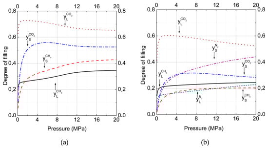
Figure 1.
Degree of cage filling for large and small cavities in hydrate at equilibrium conditions at T = 277 K. Gas phase mole fractions were (a) a binary mixture containing carbon dioxide (50%) and methane (50%) and (b) a ternary mixture containing carbon dioxide (15%), methane (15%), and nitrogen (70%) ( = solid; = dashed; = dotted; = dash-dotted; = dash-dot-dotted; and = short dashed lines). The total number of calculated points was equal to 200 with a pressure step of 0.1 MPa for each curve.
Figure 2a,b show the change of CO2 and CH4 mole fractions in binary hydrates in dependence on pressure for two gas phase compositions at T = 273 K. Analogous data of mole fractions changed for CO2, CH4, and N2 in ternary hydrates at T = 273 K and are presented in Figure 3. The arrows show the equilibrium formation points for hydrates. The intriguing result was that with pressure increasing, the CO2 fraction in hydrate decreased while the CH4 fraction grew. Such behavior correlated with results for the filling of large and small cavities (Figure 1a).
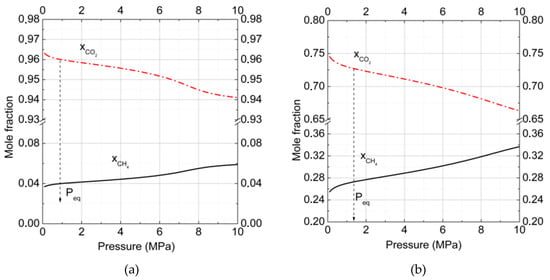
Figure 2.
Mole fraction of carbon dioxide and methane in binary hydrates at T = 273 K. The gas phase consisted of (a) carbon dioxide (90%) and methane (10%) and (b) carbon dioxide (50%) and methane (50%) (= solid and = dash-dotted lines). The total number of calculated points was equal to 100 with a pressure step of 0.1 MPa for each curve.
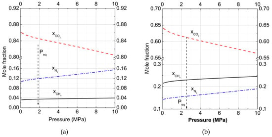
Figure 3.
Mole fraction of carbon dioxide, methane, and nitrogen in ternary hydrate phases at T = 273 K. The gas phase consisted of (a) carbon dioxide (27%) and methane (3%) with nitrogen (70%), and (b) carbon dioxide (15%), methane (15%), and nitrogen (70%) (= solid; = dashed; and = dash-dotted lines). The total number of calculated points was equal to 100 with a pressure step of 0.1 MPa for each curve.
Another interesting finding was that the CO2 fraction decrease rate in the hydrate phase was small for high CO2 concentrations in the gas phase (Figure 2a), and it increased with CO2 concentration decreases. At the temperature T = 273 K (Figure 2a,b), in the pressure interval 1 to 10 MPa for the gas mixture of 90% CO2 and 10% CH4, the change of or was about 0.022 whereas for the gas mixture of 50% CO2 + 50% CH4 it became about 0.082, almost four times larger.
After the addition of nitrogen to the binary carbon dioxide + methane mixture (Figure 3), the amount of these gases stored in the hydrate phase decreased, but not drastically. At the formation pressure (1.8 MPa at T = 273 K) for the ternary gas mixture of 27% CO2 + 3% CH4 + 70% N2, (Figure 3a), the relative fraction of CO2 in the hydrate was found to be 0.847 instead of 0.96 for the binary mixture 90% CO2 + 10% CH4. Methane with its low content in the gas phase (3%) had a fractional content of 0.035. In comparison to the hydrate phase formed from the ternary gas mixture 15% CO2 + 15% CH4 + 70% N2 (Figure 3b), the situation changed notably. At first, methane occupied a notable part of hydrate cavities and the mole fraction of methane reached 0.229 at the formation pressure. Nitrogen content in hydrate became 0.163, almost 40% higher than in the previous case. Methane and nitrogen could replace carbon dioxide in cavities, but CO2 molecules still occupied more than 60% of cavities (mole fraction is 0.614). The increase of relative gas fraction contents in hydrates with pressure was almost equal for different gas phase compositions (0.06 for 27% CO2 and 0.08 for 15% CO2 in gas mixtures).
In all considered systems with and without N2, at high and medium content of CO2 in the gas phase, we found that CO2 was more favorable in occupying clathrate hydrate cavities than CH4 or N2. Moreover, the addition of N2 to the gas phase increased the ratio. For mixtures of 50% CO2 + 50% CH4 and 15% CO2 + 15% CH4 + 70% N2, this ratio increased by 1.5%, and for mixtures of 90% CO2 + 10% CH4 and 27% CO2 + 3% CH4 + 70% N2, by about 1%. Therefore, the addition of N2 made gas replacement more effective.
3.2.Gas–Hydrate–Ice (Water)Phase Equilibria
We conducted a calculation of P-T diagrams for gas–hydrate–ice (water) phase equilibria (described by Equations (10) and (11), carried out earlier) for one-component hydrates of methane and reproduced the experimental data with good accuracy [45,46].
The modeling was performed within the molecular model framework described above: Here such calculations were conducted for carbon dioxide hydrates. The obtained lines of the phase equilibria also were in reasonable agreement with the experimental data. In Figure 4, the calculated curves of the ice–gas–hydrate phase equilibria are presented for the considered one-component hydrates of carbon dioxide and methane as well as the available experimental data [6] for comparison.
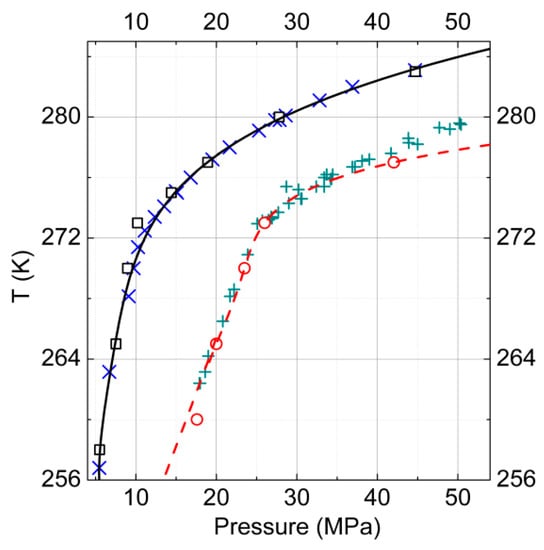
Figure 4.
P-T diagram of gas–hydrate–ice (water) phase equilibria for one-component hydrates of carbon dioxide and methane. The results of the calculations for carbon dioxide are represented by the open squares, and the experimental data [6] by the skew crosses. For methane, the calculated data are shown by open circles and the experimental data [6] by crosses.
The calculation of hydrate formation pressure as well as the CO2 fraction in the hydrate phase in dependence on the gas phase composition were performed for binary CO2 + CH4 mixtures at temperatures of 273 K and 277 K (Figure 5a,b). The temperatures were chosen in order to describe gas equilibria for both gas–hydrate–ice and gas–hydrate–water.
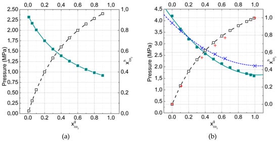
Figure 5.
P-x diagram of the binary hydrates of methane and carbon dioxide at (a) T = 273 K and (b) T = 277 K. Skew crosses = the experimental data [47] of mole fraction carbon dioxide in the hydrate phase; crosses = experimental data [47].
It is notable that carbon dioxide molecules filled cages better than methane. For example, at the temperature 273 K, the hydrate formation pressure and equimolar composition of the gas phase (50% methane, 50% carbon dioxide), the fraction of CO2 molecules in hydrate reached 73% and the fraction of CH4 about 27%. At the temperature 277 K, the fractions of gas molecules in hydrate were 70% and 30%, respectively. The ratio of occupancies by CO2 and CH4 was 2.7:1 at 273 K and 2.3:1 at 277 K. These calculation results agreed well with the experimental data [47]. It has to be noted that with increasing temperature, the fraction of CO2 in hydrate decreased. That could be connected with the increase of pressure, which was necessary for gas hydrate formation. In this case, the methane molecules could concur with the carbon dioxide molecules to occupy mainly small hydrate cavities.
It was connected with the more suitable size of hydrate small cavities for methane molecules in spite of their weaker interactions with surrounding water molecules. In Table 1, the data for binary hydrates formation conditions at several temperatures and gas phase compositions are presented. Calculations were performed for water–gas–hydrate equilibria (T = 277 K) and for ice–gas–hydrate equilibria (T = 273 K, 258 K).

Table 1.
P-T-x equilibria of ice (water)–gas–hydrate systems for the CO2 + CH4 gas mixture.
At relatively low pressures, the solubility of considered gases in ice and water was neglected in our calculations. As could be expected, the equilibrium pressure in systems of gas–hydrate–ice (water) increased with temperature and decreased with a rising amount of carbon dioxide in the gas phase. Analysis of the data also showed nontrivial increasing of the carbon dioxide mole fraction in hydrate with decreasing temperature. That could be connected with the lowering formation pressure while temperature decreased. We could conclude that at low pressure, methane was less favorable than carbon dioxide in cavities occupation.
The formation pressure of binary hydrates rose with increasing methane content in the gas phase and increasing temperature. With temperatures of about 277 K, which corresponds to water temperatures near the bottom of oceans, methane hydrates could form and exist in thermodynamic equilibrium with water and gas at the pressure 4.2 MPa, corresponding to 420 meters in depth (depths of continental slope), whereas for the one-component hydrate of carbon dioxide the formation pressure was lower, 1.2 MPa. At lower temperatures (273 K, 258 K), the decrease of the hydrate formation pressure with the addition of carbon dioxide to methane became not so significant. Thus, with methane content diminishing from 100% to 0%, the change in the formation pressure at T = 273 K was about 1.5 MPa and at T = 258 K, it was about 0.8 MPa.
With an increase of methane content in the gas phase, the hydrate formation pressure gradually rose. The formation pressure of double hydrates of methane and carbon dioxide appeared to be a linear function of the methane content in the hydrate. This was remarkable having in mind the significant difference in interaction strengths between the guest molecules (carbon dioxide–carbon dioxide, methane–methane).
The calculations of the formed hydrates composition at different temperatures showed that for replacement of methane in hydrate by carbon dioxide, the low temperature was preferable.
To understand the influence of additional nitrogen into the carbon dioxide gas phase on hydrate formation conditions and compositions, the dependencies of the formation pressure and mole fraction of CO2 in hydrate on the gas phase composition for temperatures of T = 272 K (equilibria of gas–hydrate–ice) and T = 274 K (equilibria of gas–hydrate–water), and in the range for CO2 mole fractions from 0.0 to 1.0 in the gas phase (Figure 6a,b), were found.
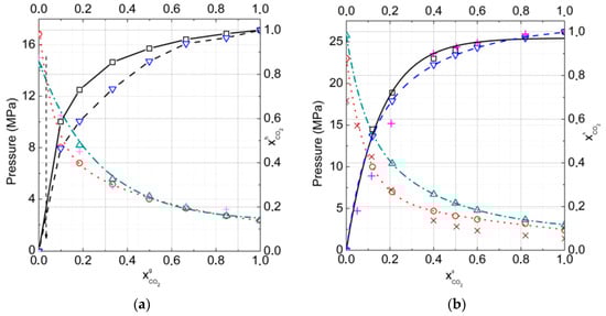
Figure 6.
Gas–hydrate–ice (water)phase equilibria for carbon dioxide and nitrogen gas mixtures for cubic structure (CS)-I and CS-II hydrates in comparison with the experimental data, skew crosses [25] and crosses [27], at (a) T = 272 K and (b) T = 274 K, respectively ( is dotted by open circles, is dash-dotted by open triangles, is represented by solid open square, and is represented by dashed open inverted triangle lines).
The calculations showed that for all gas phase compositions, the fraction of CO2 of more than 0.035 was higher in the hydrate phase relative to the gas phase, and the hydrate structure CS-I appeared to be more stable than structure CS-II. Whereas for all gas phase compositions the fraction of CO2 less than 0.035 was higher in the hydrate phase relative to the gas phase, the hydrate structure CS-II appeared to be more stable than structure CS-I. That could be connected with the larger large-to-small cavities ratio in the CS-I structure that was more suitable for CO2 molecules. Even at 20% CO2 in the gas phase, the CO2 fraction in hydrate reached 0.75 at T = 272 K and 0.70 at T = 274 K. As one can see from Figure 6b, experimental data were described with a reasonable accuracy, at least for relatively low temperatures.
The absence of phase transition CS-I–CS-II in our results at T = 274 K could be connected with the roughness of the used approximation, in which we did not take into account the solubility of gases on water. It is not very important at low pressure, but is significant at high pressure, when N2 and CO2 solubility rapidly increase. On the other hand, one can neglect the solubility of gases on the ice at formation conditions. Another system we considered was CO2 + CH4 +N2 mixtures, which can form hydrates with water or ice. In the gas mixture, the N2 mole fraction was fixed at 0.7 and the relative content of CO2 and CH4 varied from 0.00 CO2 to 0.30 CO2 in the gas phase. At low concentration of CO2 in gas phase pressures of methane replacement by CO2 and N2 are high and it is not suitable for technology. In this case large cages of hydrate are can be partly filled by nitrogen, but CH4 recovery degree would be smaller.
In Figure 7a,b, the calculated formation pressures and mole fractions of guests in hydrates of ternary mixtures CO2 + CH4 + N2 are presented.
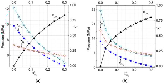
Figure 7.
Formation pressure and composition of ternary hydrates carbon dioxide, methane, and nitrogen in dependence on carbon dioxide mole fraction in the gas phase.The nitrogen mole fraction in the gas phase was fixed at a value of 0.7 at temperatures of hydrate formation (a) T = 273 K, (b) T = 277 K ( is dash-dotted by open inverted triangles, is dashed by filled squares, is solid by filled triangles, and is dotted by open circle lines).
The mole fraction of CO2 in hydrate increased rapidly with the growth of its content in the gas phase. The fraction of CO2 at equilibria both with water and with ice, even at small CO2 concentrations, was at least three times higher in the hydrate phase than in the gas mixture (Figure 7a,b). The behavior of N2 and CH4 guests at equilibria with ice and water were quite different. At equilibrium with ice, CH4 occupied many more cavities than N2 up to a 0.15 mole fraction of CH4 in the gas phase. At higher temperatures, at equilibrium with water and thus for higher formation pressures, the nitrogen became more suitable for occupation of hydrate small cavities.
The solubility of carbon dioxide in water was comparatively high and reached one mole/liter at the hydrate formation pressure and temperature (1.24 MPa at 273 K). At these conditions, the methane solubility was not higher than 0.03 mole/liter. Thus, we could conclude that even at small CO2 concentrations in the gas phase, it could be the excess in the reaction mixture that promotes the methane displacement from hydrate.
In Table 2, the calculated P-T-x equilibria conditions of gas–hydrate–ice (water) systems at 70% in the gas phase are presented.
Table 2.
P-T-x equilibria for CO2 + CH4 + N2 +H2O in gas–hydrate–ice (water) systems at 70% N2 in the gas phase.
If we assume that the formation pressure rose rapidly with the temperature and with lowering CO2 content in the gas phase, the obtained data showed very significant increases in the formation pressure after transition from ice to liquid water.
4. Conclusions
In this work, the method based on the solid solution theory of clathrate hydrate [34,35,36,37,38] was presented to investigate the effects of the influence of nitrogen on the equilibrium pressure and on the hydrate composition of clathrate hydrates formed from methane + carbon dioxide and nitrogen + carbon dioxide binary gas and methane + carbon dioxide + nitrogen ternary gas mixtures. The comparison of cavities’ filling degrees for binary CO2 + CH4 with ternary CO2 + CH4 + N2 mixed hydrates showed that carbon dioxide molecules occupied both small and large cavities more preferably than methane, but in the case of ternary mixed hydrate, cavities occupation by N2, molecules could be concurred by CO2 and CH4 molecules.
In all considered systems with and without N2, at high and medium CO2 content in the gas phase, we found that CO2 was more favorable in occupying clathrate hydrate cavities than CH4 or N2. The addition of N2 into the gas phase increased the ratio concentration of CO2 in comparison with the concentration of CH4 in clathrate hydrates and made gas replacement more effective. The calculation results of the CO2 + CH4 hydrates confirmed that for all gas phase compositions, the fraction of CO2 was higher in the hydrate phase relative to the gas phase, and the hydrate structure CS-I appeared to be more stable than structure CS-II. The mole fraction of CO2 in the CO2 + CH4 + N2 gas hydrate increased rapidly with the growth of its content in the gas, and the formation pressure of the CO2 + CH4 + N2 gas hydrate rose in comparison with the formation pressure of the CO2 + CH4 gas hydrate. Our calculated data were compared with the experimental data [6,25,47], and it was shown that the used theory generally over predicted the experimental data.
Author Contributions
Conceptualization, V.R.B.; methodology, O.S.S.; software, R.K.Z; validation, K.V.G., Y.Y.B., and Y.K.; formal analysis, R.V.B.; investigation, O.S.S.; data curation, Y.Y.B.; writing—original draft preparation, Y.Y.B.; writing—review and editing, O.S.S.; supervision, V.R.B.; funding acquisition, V.R.B.
Funding
This research was funded by the Russian Science Foundation, grant number [18-19-00124].
Acknowledgments
We would like to express also our sincere thanks to the crew of the Center for Computational Materials Science of the Institute for Materials Research, Tohoku University for their continuous support.
Conflicts of Interest
The authors declare no conflicts of interest.
References
- Marchetti, C. On geoengineering and the CO2 problem. Clim. Chang. 1977, 1, 59–68. Available online: https://link.springer.com/article/10.1007/BF00162777 (accessed on 13 December 2018). [CrossRef]
- Stevens, S.H.; Kuuskraa, V.A.; Gale, J.; Beecy, D. CO2 injection and sequestration in depleted oil and gas fields and deep coal seams: Worldwide potential and costs. Environ. Geosci. 2001, 8, 200–209. [Google Scholar] [CrossRef]
- Ohgaki, K. Proposal for gas storage on the ocean floor using gas hydrate. Kagaku Kogaku Ronbunshu 1991, 17, 1053–1055. [Google Scholar] [CrossRef]
- House, K.Z.; Schrag, D.P.; Harvey, C.F.; Lackner, K.S. Permanent carbon dioxide storage in deep-sea sediments. Proc. Nat. Acad. Sci. USA 2006, 103, 12291–12295. [Google Scholar] [CrossRef] [PubMed]
- Stern, L.A.; Kirby, S.H.; Durham, W.B. Peculiarities of methane clathrate hydrate formation and solid-state deformation, including possible superheating of water ice. Science 1996, 273, 1843–1848. [Google Scholar] [CrossRef]
- Sloan, E.D., Jr.; Koh, C. Clathrate Hydrates of Natural Gases, 3rd ed.; CRC Press: Boca Raton, FL, USA, 2007; pp. 1–752. [Google Scholar]
- Lee, H.; Seo, Y.; Seo, Y.T.; Moudrakovski, I.L.; Ripmeester, J.A. Recovering methane from solid methane hydrate with carbon dioxide. Angew. Chem. Int. Ed. 2003, 42, 5048–5051. [Google Scholar] [CrossRef] [PubMed]
- Park, Y.; Kim, D.Y.; Lee, J.W.; Huh, D.G.; Park, K.P.; Lee, J.; Lee, H. Sequestering carbon dioxide into complex structures of naturally occurring gas hydrates. Proc. Nat. Acad. Sci. USA 2006, 103, 12690–12694. [Google Scholar] [CrossRef]
- Shin, K.; Park, Y.; Cha, M.; Park, K.P.; Huh, D.G.; Lee, J.; Lee, H. Swapping phenomena occurring in deep-sea gas hydrates. Energy Fuel 2008, 22, 3160–3163. [Google Scholar] [CrossRef]
- Brewer, P.G.; Friederich, G.; Peltzer, E.T.; Orr, F.M. Direct experiments on the ocean disposal of fossil fuel CO2. Science 1999, 284, 943–945. [Google Scholar] [CrossRef] [PubMed]
- Koh, D.Y.; Kang, H.; Kim, D.O.; Park, J.; Cha, M.; Lee, H. Recovery of methane from gas hydrates intercalated within natural sediments using CO2 and a CO2/N2 gas mixture. ChemSusChem 2012, 5, 1443–1448. [Google Scholar] [CrossRef]
- Kvamme, B.; Graue, A.; Buanes, T.; Kuznetsova, T.; Ersland, G. Storage of CO2 in natural gas hydrate reservoirs and the effect of hydrate as an extra sealing in cold aquifers. Int. J. Greenh. Gas Con. 2007, 1, 236–246. [Google Scholar] [CrossRef]
- Seo, Y.T.; Lee, H. Multiple-phase hydrate equilibria of the ternary carbon dioxide, methane, and water mixtures. J. Phys. Chem. B 2001, 105, 10084–10090. [Google Scholar] [CrossRef]
- Belosludov, V.R.; Subbotin, O.S.; Belosludov, R.V.; Mizuseki, H.; Kawazoe, Y. Thermodynamic phase behavior of binary clathrate hydrates: Computational prediction. Comput. Mater. Sci. 2010, 49, S187–S193. [Google Scholar] [CrossRef]
- Adamova, T.P.; Subbotin, O.S.; Pomeransky, A.A.; Belosludov, V.R. Modeling of phase transition sI−sII in binary gas hydrates of methane and ethane in dependence on composition of gas phase. Comput. Mater. Sci. 2010, 9, S317–S321. [Google Scholar] [CrossRef]
- Tung, Y.T.; Chen, L.J.; Chen, Y.P.; Lin, S.T. In situ methane recovery and carbon dioxide sequestration in methane hydrates: A molecular dynamics simulation study. J. Phys. Chem. B 2011, 115, 15295–15302. [Google Scholar] [CrossRef] [PubMed]
- Belosludov, R.V.; Zhdanov, R.K.; Subbotin, O.S.; Mizuseki, H.; Souissi, M.; Kawazoe, Y.; Belosludov, V.R. Theoretical modelling of the phase diagrams of clathrate hydrates for hydrogen storage applications. Mol. Simulat. 2012, 38, 773–780. [Google Scholar] [CrossRef]
- Bozhko, Y.Y.; Subbotin, O.S.; Gets, K.V.; Zhdanov, R.K.; Belosludov, V.R. Theoretical modeling of the gas hydrates of nitrous oxide and methane mixtures. Mendeleev Commun. 2017, 27, 397–398. [Google Scholar] [CrossRef]
- Zhdanov, R.K.; Gets, K.V.; Belosludov, R.V.; Subbotin, O.S.; Bozhko, Y.Y.; Belosludov, V.R. Theoretical modeling of the thermodynamic properties and the phase diagram of binary gas hydrates of argon and hydrogen. Fluid Phase Equilibria 2017, 434, 87–92. [Google Scholar] [CrossRef]
- Belosludov, R.V.; Zhdanov, R.K.; Subbotin, O.S.; Mizuseki, H.; Kawazoe, Y.; Belosludov, V.R. Theoretical study of hydrogen storage in binary hydrogen-methane clathrate hydrates. J. Renew. Sust. Energy 2014, 6, 053132. [Google Scholar] [CrossRef]
- Bozhko, Y.Y.; Subbotin, O.S.; Fomin, V.M.; Belosludov, V.R.; Kawazoe, Y. Theoretical investigation of structures, compositions, and phase transitions of neon hydrates based on ices Ih and II. J. Eng. Thermophys. 2014, 23, 20–26. [Google Scholar] [CrossRef]
- Belosludov, R.V.; Subbotin, O.S.; Mizuseki, H.; Kawazoe, Y.; Belosludov, V.R. Accurate description of phase diagram of clathrate hydrates at the molecular level. J. Phys. Chem. 2009, 131, 244510. [Google Scholar] [CrossRef]
- Seo, Y.T.; Lee, H.; Yoon, J.H. Hydrate phase equilibria of the carbon dioxide, methane, and water system. J. Chem. Eng. Data 2001, 46, 381–384. [Google Scholar] [CrossRef]
- Belandria, V.; Mohammadi, A.H.; Richon, D. Phase equilibria of clathrate hydrates of methane + carbon dioxide: New experimental data and predictions. Fluid Phase Equilibria 2010, 296, 60–65. [Google Scholar] [CrossRef]
- Kang, S.P.; Lee, H.; Lee, C.S.; Sung, W.M. Hydrate phase equilibria of the guest mixtures containing CO2, N2 and tetrahydrofuran. Fluid Phase Equilibria 2001, 185, 101–109. [Google Scholar] [CrossRef]
- Seo, Y.T.; Moudrakovski, I.L.; Ripmeester, J.A.; Lee, J.W.; Lee, H. Efficient recovery of CO2 from flue gas by clathrate hydrate formation in porous silica gels. Environ. Sci. Technol. 2005, 39, 2315–2319. [Google Scholar] [CrossRef] [PubMed]
- Seo, Y.T.; Lee, H. Structure and guest distribution of the mixed carbon dioxide and nitrogen hydrates as revealed by X-ray diffraction and 13C-NMR spectroscopy. J. Phys. Chem. B 2004, 108, 530–534. [Google Scholar] [CrossRef]
- Seo, Y.T.; Lee, H.; Uchida, T. Methane and carbon dioxide hydrate phase behavior in small porous silica gels: Three-phase equilibrium determination and thermodynamic modeling. Langmuir 2002, 18, 9164–9170. [Google Scholar] [CrossRef]
- Waals, J.V.D.; Platteeuw, J.C. Clathrate solutions. Adv. Chem. Phys. 1959, 2, 1–58. [Google Scholar]
- Kuhs, W.F.; Chazallon, B.; Radaelli, P.G.; Pauer, F. Cage occupancy and compressibility of deuterated N2-clathrate hydrate by neutron diffraction. J. Incl. Phenom. Macrocycl. Chem. 1997, 29, 65–77. [Google Scholar] [CrossRef]
- Chazallon, B.; Kuhs, W.F. In situ structural properties of N2−, O2−, and air-clathrates by neutron diffraction. J. Chem. Phys. 2002, 117, 308–320. [Google Scholar] [CrossRef]
- Van Klaveren, E.P.; Michels, J.P.J.; Schouten, J.A.; Klug, D.D.; Tse, J.S. Stability of doubly occupied N2 clathrate hydrates investigated by molecular dynamics simulations. J. Chem. Phys. 2001, 114, 5745–5754. [Google Scholar] [CrossRef]
- van Klaveren, E.P.; Michels, J.P.J.; Schouten, J.A.; Klug, D.D.; Tse, J.S. Molecular dynamics simulation study of the properties of doubly occupied N2 clathrate hydrates. J. Chem. Phys. 2001, 115, 10500–10508. [Google Scholar] [CrossRef]
- Belosludov, V.R.; Subbotin, O.S.; Krupskii, D.S.; Belosludov, R.V.; Kawazoe, Y.; Kudoh, J.I. Physical and chemical properties of gas hydrates: Theoretical aspects of energy storage application. Mater. Trans. 2007, 48, 704–710. [Google Scholar] [CrossRef]
- Subbotin, O.S.; Adamova, T.P.; Belosludov, R.V.; Mizuseki, H.; Kawazoe, Y.; Kudoh, J.I.; Belosludov, V.R. Theoretical study of phase transitions in Kr and Ar clathrate hydrates from structure II to structure I under pressure. J. Chem. Phys. 2009, 131, 114507. [Google Scholar] [CrossRef]
- Souissi, M.; Belosludov, R.V.; Subbotin, O.S.; Mizuseki, H.; Kawazoe, Y.; Belosludov, V.R. Thermodynamic stability of C3H8 hydrate of cubic structure IV using lattice dynamics. J. Incl. Phenom. Macrocycl. Chem. 2011, 69, 281–286. [Google Scholar] [CrossRef]
- Belosludov, R.V.; Bozhko, Y.Y.; Subbotin, O.S.; Belosludov, V.R.; Mizuseki, H.; Kawazoe, Y.; Fomin, V.M. Stability and composition of helium hydrates based on ices Ih and II at low temperatures. J. Phys. Chem. C 2014, 118, 2587–2593. [Google Scholar] [CrossRef]
- Bozhko, Y.Y.; Subbotin, O.S.; Fomin, V.M.; Belosludov, V.R.; Kawazoe, Y. Theoretical investigation of structures and compositions of double neon-methane clathrate hydrates, depending on gas phase composition and pressure. J. Eng. Thermophys. 2014, 23, 9–19. [Google Scholar] [CrossRef]
- Jager, M.D.; Ballard, A.L.; Sloan, E.D., Jr. The next generation of hydrate prediction: II. dedicated aqueous phase fugacity model for hydrate prediction. Fluid Phase Equilibria 2003, 211, 85–107. [Google Scholar] [CrossRef]
- Bernal, J.D.; Fowler, R.H. A theory of water and ionic solution, with particular reference to hydrogen and hydroxyl ions. J. Chem. Phys. 1933, 1, 515–548. [Google Scholar] [CrossRef]
- Berendsen, H.J.C.; Grigera, J.R.; Straatsma, T.P. The missing term in effective pair potentials. J. Phys. Chem. 1987, 91, 6269–6271. [Google Scholar] [CrossRef]
- Martin, M.G.; Siepmann, J.I. Transferable potentials for phase equilibria. 1. United-atom description of n-alkanes. J. Phys. Chem. B 1998, 102, 2569–2577. [Google Scholar] [CrossRef]
- Fomin, V.V. NASA Technical Memorandum NASA TM-75655. Available online: https://ntrs.nasa.gov/search.jsp?R=19790021554 (accessed on 13 December 2018).
- Vishnyakov, A.; Debenedetti, P.G.; Neimark, A.V. Statistical geometry of cavities in a metastable confined fluid. Phys. Rev. E 2000, 62, 538. [Google Scholar] [CrossRef]
- Zhdanov, R.K.; Adamova, T.P.; Subbotin, O.S.; Pomeranskii, A.A.; Belosludov, V.R.; Dontsov, V.R.; Nakoryakov, V.E. Modeling the properties of methane + ethane (Propane) binary hydrates, depending on the composition of gas phase state in equilibrium with hydrate. J. Eng. Thermophys. 2010, 19, 282–288. [Google Scholar] [CrossRef]
- Subbotin, O.S.; Bozhko, Y.Y.; Zhdanov, R.K.; Gets, K.V.; Belosludov, V.R.; Belosludov, R.V.; Kawazoe, Y. Ozone storage capacity in clathrate hydrates formed by O3+ O2+ N2+ CO2 gas mixtures. Phys. Chem. Chem. Phys. 2018, 20, 12637–12641. [Google Scholar] [CrossRef] [PubMed]
- Herri, J.M.; Bouchemoua, A.; Kwaterski, M.; Fezoua, A.; Ouabbas, Y.; Cameirão, A. Gas hydrate equilibria for CO2–N2 and CO2–CH4 gas mixtures—Experimental studies and thermodynamic modelling. Fluid Phase Equilibria 2011, 301, 171–190. [Google Scholar] [CrossRef]
Sample Availability: Samples of the compounds are not available from the authors. |
© 2018 by the authors. Licensee MDPI, Basel, Switzerland. This article is an open access article distributed under the terms and conditions of the Creative Commons Attribution (CC BY) license (http://creativecommons.org/licenses/by/4.0/).