1. Introduction
Interest in studying man-machine interfaces has continued to grow, especially for immersive virtual environment applications and for input devices for portable machines. To achieve more realistic object manipulation, glove-based input devices are commonly chosen as the human-machine interfaces of virtual reality (VR) applications. The data glove is a multi-sensory device that generates a large amount of data and is more complex than other input devices. Nonetheless, most researchers still adopt this device because the natural interfacing characteristic of the data glove with human being is the way to improve system manipulations that are applicable in many specific fields. At present, the data glove has been increasingly employed in the areas of teleoperations and robotic control [
1–
3], surgery training of medical applications [
4,
5], entertainment sports (VR systems) [
6,
7], industrial manufacturing of CAD/CAM applications [
8,
9], text input devices [
10–
12], and so on.
The hand-tracking gloves currently marketed include: Sayre Glove, MIT LED Glove, Digital Data-Entry Glove, DataGlove, Dexterous HandMaster, Power Glove, CyberGlove, VPL Glove, and Space Glove [
13]. Nowadays, several kinds of sensing technologies have been realized and applied to the development of data gloves. Most of these data gloves provide high accuracy, high reliability, and high capability in measuring the degree of freedom (DOF) of human hands [
14–
17]. Most of them are constructed using sensors that measure the bending angles of fingers. Although the glove sensors can measure all of the bending angles precisely, the precision of object grasping in the virtual environment is not guaranteed due to the variation in size of a user’s hand wearing the data glove.
The gloves are also mostly built with flex sensors attached on the finger joint positions of the hand. When the fingers are bent, the sensors are also bent and the generated outputs are measured. Based on these outputs, the bending angles of the fingers are calculated. When users wear the data gloves, the stretching and bending of the finger joints occur very frequently. This reduces the lifetime of the sensors and the accuracy of measurements. According to the sensor outputs, the data gloves can be grouped into two classes: one type produces linear outputs, and another produces nonlinear outputs. Either linear or nonlinear data gloves should be calibrated before they are activated in the particular applications. Compared to linear data gloves, the calibration process of nonlinear data gloves is not so easy, owing to the lack of output references of nonlinear sensors [
18]. The following depicts the most commonly used sensors for hand tracking applied to the development of glove-based input devices:
Acoustic tracking sensor
This kind of sensor uses high frequency audio signals to track the movements of fingers. Such sensors may suffer from acoustic reflections if they are surrounded with hard walls or other acoustically reflective surfaces.
Optical tracking sensor
This sensor generally uses an LED or infra-red signal as the source which is conducted toward a transmission media like flexible tubes or fiber optics. Then a photocell sensor is placed at the other end of the media to measure the intensity of the signal.
Magnetic tracking sensor
It uses a source element radiating a magnetic field and a small sensor that reports its position and orientation with respect to the source. The magnetic field may be interfered by metallic objects in the environment, which decrease the accuracy of measurement.
Resistance tracking sensor
This sensor uses a variable resistance material whose resistivity is varied according to the bending degree of the sensor.
In order to achieve high capability in measuring the DOF of a hand, a lot of sensors should be attached to the data glove, each of which is usually installed on the finger joint position. Low cost data gloves that contain few sensors are available today on the market. However, this kind of data gloves can only measure a few DOF of the hand, so it does not appropriately act as an input device for most of the VR systems that require a high DOF of the hand.
In this paper, we present the development of a sensory data glove that contains only five sensor modules and one sensor coil, but still possesses the ability to measure high numbers of DOF of the hand. Instead of measuring the bending angles of finger joints directly, we track the positions and orientations of fingertips with respect to the metacarpals, so that there is no direct contact point between sensors and finger joints, and thus, the quality of measurement and the lifetime of the sensors will not decrease in time. We also propose a method for constructing the shape of the finger, and based on this shape, the bending angle of the finger joints can be calculated. By measuring the positions of the fingertips, the object grasping process in a virtual environment can be performed more precisely, because in most of such processes, the fingertips are the foremost areas that reach the surface of an object. Using magnetic induction technology, we constructed the data glove sensors, which provide high accuracy of measurement. To avoid the interference of metallic objects in the environment, the sensors and the electromagnetic sources on the glove are arranged in such a way to ensure that the distances between them are near enough, so that the measurement error caused by metallic objects can be ignored.
In the light of the magnetic induction theory, the position and orientation of a single coil sensor can be uniquely described by three position and two orientation parameters. To solve these parameters, a minimum of five equations are needed. If more equations are incorporated, more sensors should be added such that the complexity of the data glove system will increase. To reduce the number of sensors, we design a sensor module that can be used for measuring the fingertip position. The positions of the sensors on the data glove are carefully arranged and the motion constraints among the fingers and the finger joints of the hand [
19] are also investigated. The theoretical formulation of the fingertip positions, abduction angles, and the calibration equations are derived directly from the positions and orientations of the sensors in which the motion constrains of the hand are applied.
To make the glove easy to use, a simple and efficient calibration process consisting of only one calibration gesture is proposed, too. The parameters required for calculating the fingertip positions are immediately determined from the calibration equations that are also derived from the positions and orientations of the sensors on the data glove. In the realization of the data glove, ten generator coils arranged into five groups are attached on the metacarpals, while five associated sensor modules are installed on the fingertips of the hand. Additionally one sensor coil is placed on the metacarpal of the middle index for measuring the abduction angles. These ten generator coils tend to interfere with each other if they are not appropriately controlled, and all of the sensors will not produce accurate results. To overcome this problem, three scanning methods are evaluated and the time division technique is eventually adopted in developing the prototype of our data glove.
2. The Construction of the Data Glove Sensor
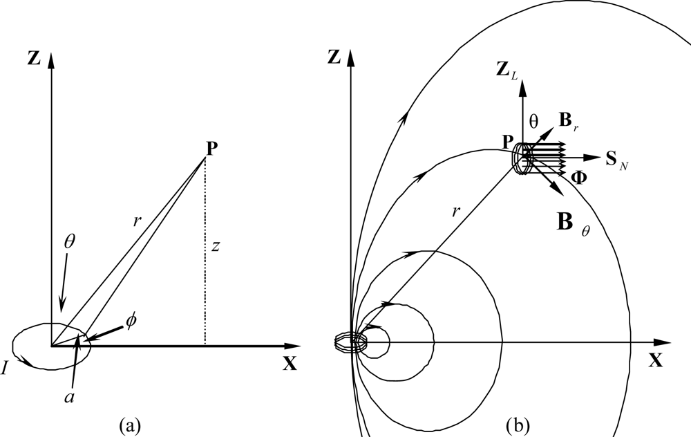
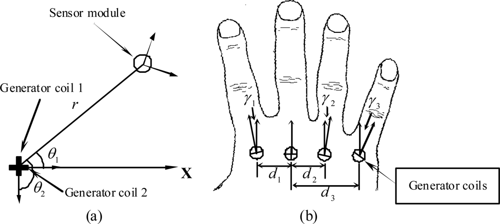
The sensor of the data glove we have developed is made of small coils (the sensor coils) that are installed on the fingertip positions of the hand. The magnetic flux generators are also made of small coils (the generator coils) activated by sinusoidal waveform generators. Each generator coil may be represented as a magnetic dipole that can be modeled by a single analytical equation. The magnetic dipole is a current loop whose dimensions are much smaller than the distance between the loop and an observation point. The magnetic field at point
P with distance
r from a circular dipole as shown in
Figure 1a is given by:
where
Bγ,
Bθ and
Bϕ are the magnetic fields in the directions
aγ,
aθ, and
aϕ of the spherical coordinates system, respectively,
μ0 = 4
π × 10
−9 H/cm is the magnetic permeability of a free space,
N is the number of turns,
I is the coil current,
a is the radius of the coil, and
r >>
a.When a single coil sensor is placed at point
P where the magnetic field intensity is varied in time, the electromotive force (
Emf) induced in the coil is expressed by the following equation:
where
ϕ is the magnetic flux density linking the coil and
Nc is the number of turns of the coil. The negative sign indicates the direction of the induced current opposite to that of the change of the magnetic flux density. The magnetic flux density linked by the coil depends on the position and orientation of the coil in the magnetic field, as
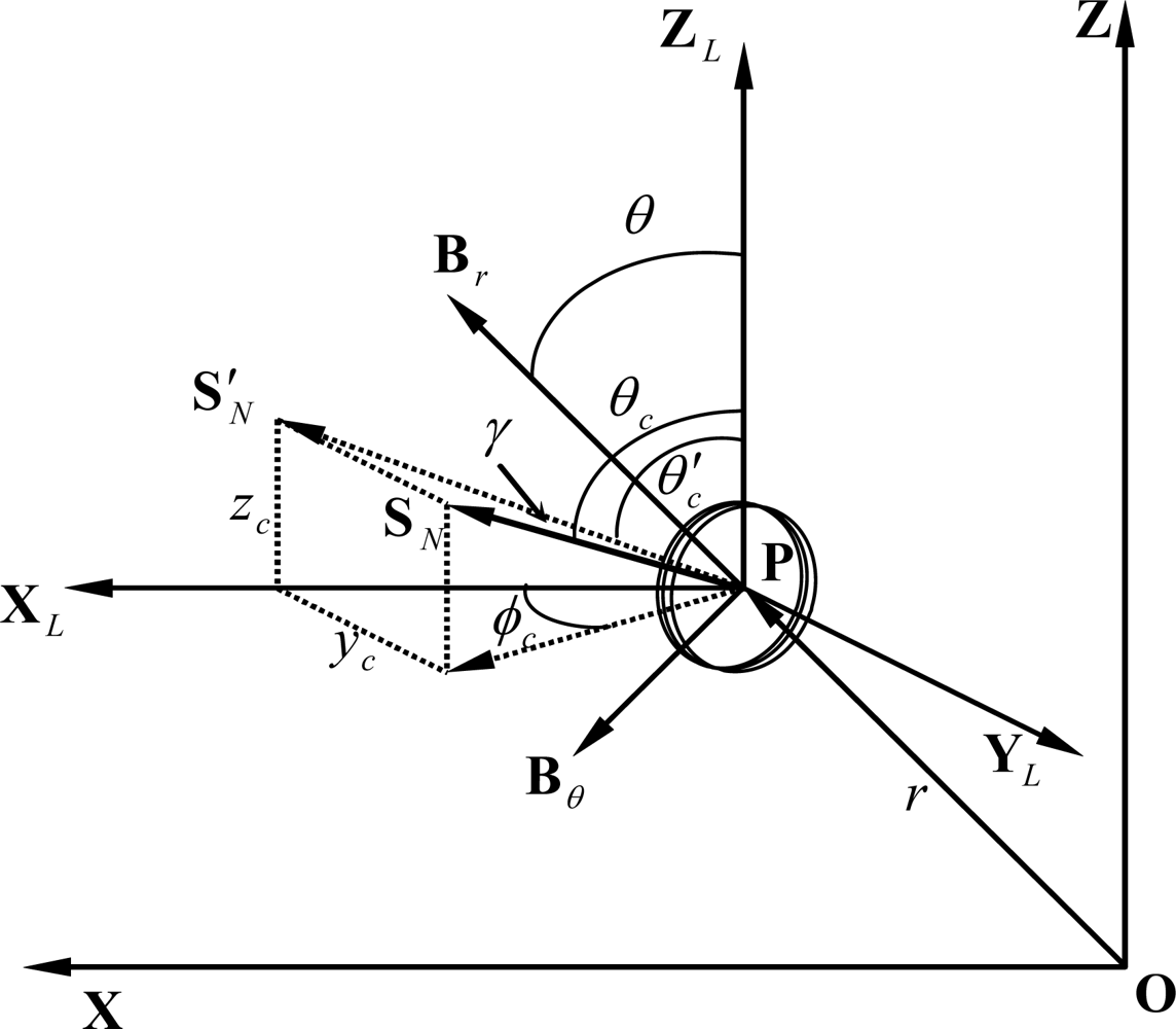
Figure 1(b) shows. Since
Bϕ = 0, we can assume that the position of point
P is always in the
xz-plane. The orientation of the coil at point
P can be represented by
θc measured from the
ZL-axis and
ϕc measured from the
XL-axis as shown in
Figure 2, where
XL,
YL, and
ZL represent the local coordinates system of the coil.
The magnetic field intensity in the direction
SN can be calculated by projecting
SN into the
xz-plane. The procedure of calculating this magnetic field intensity is stated below:
Then the magnetic flux density linked by the coil with radius
b yields:
By substituting B
γ and B
θ from (1) into (4), the magnetic flux density becomes:
From (2), the induced electromotive force can be written as the function of the position in the
yz-plane and the orientation of the sensor coil. This equation yields:
where
.
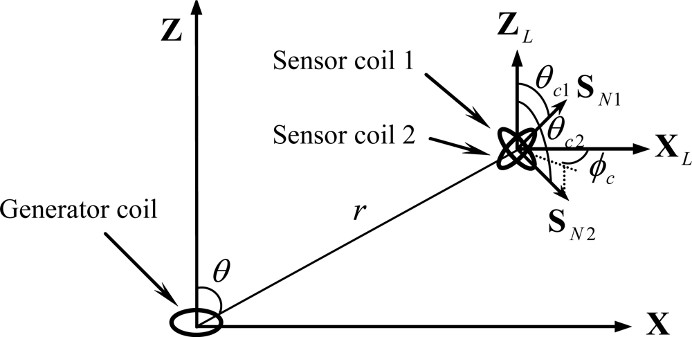
In the development of the data glove, two identical sensor coils are combined to produce a sensor module. These two coils are arranged such that they are co-centered and perpendicular, as illustrated in
Figure 3.
Since the two sensor coils are perpendicular, the orientation of the second sensor coil can be expressed as:
By substituting (7) into (6), the square of the
Emf signals produced by the two sensor coils become:
where
W = 3cos2
θ + 1. Consequently, the power
Emf signal of the sensor module, which is defined as the sum of the square of the
Emf signals of the two sensor coils with respect to the generator coil, can be derived from (8) and listed in the following:
If
ϕc = 0, the equation above can be further simplified as:
3. The Construction of the Data Glove
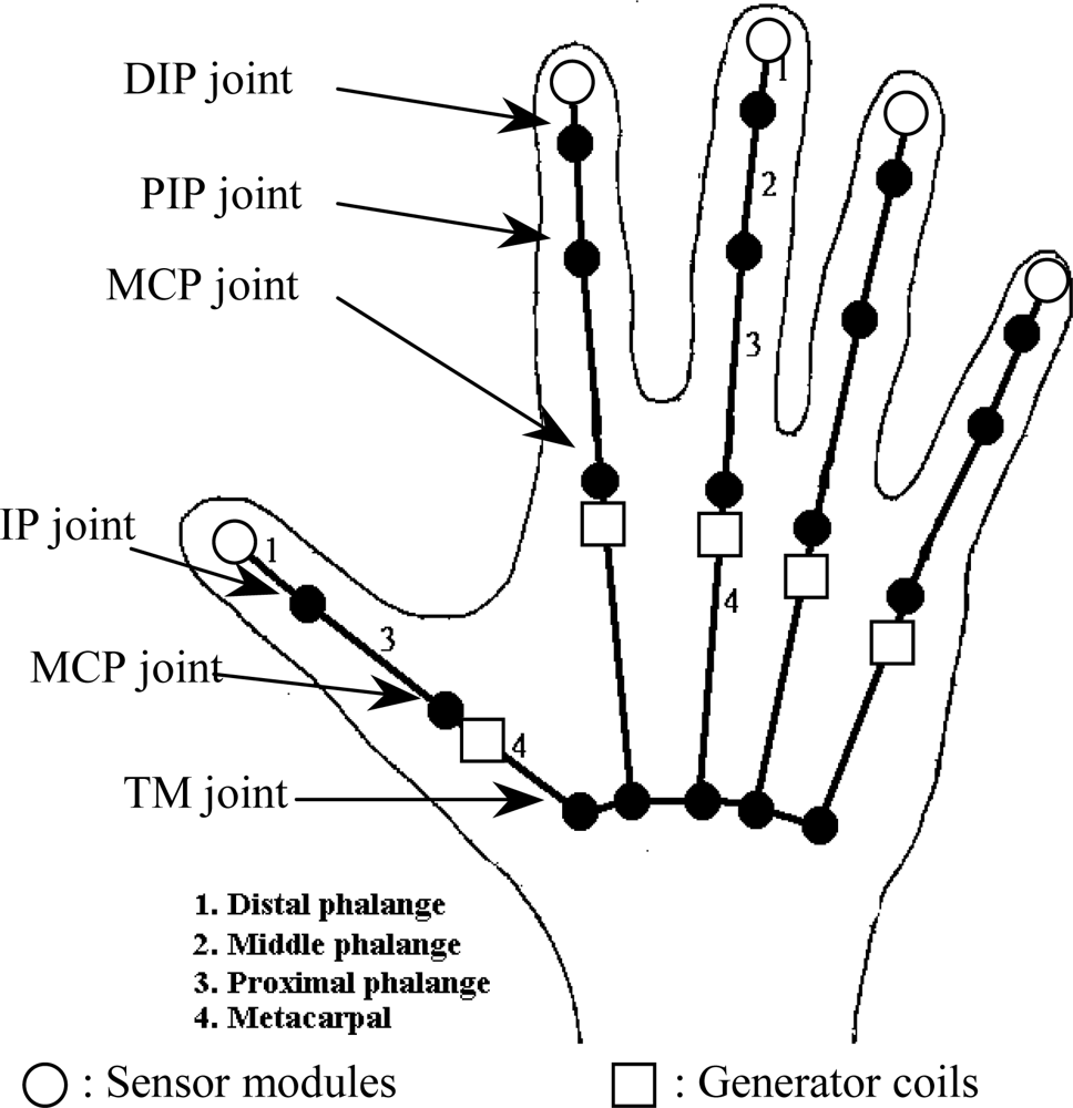
To track the fingertip positions efficiently, the orientations and locations of the sensor modules associated with the generator coils should be carefully arranged on a user’s hand. Instead of placing them on the finger joint positions, the sensor modules are attached on the fingertips and the generator coils are placed near to the metacarpophalangeal (MCP) joints on the dorsal surface of the metacarpals. The distances between the generator coils and sensor modules are close enough such that the potential interference caused by a metallic object with the distance greater than 20 cm from the data glove can be ignored.
Owing to the highly articulated characteristic of a human hand, it possesses approximately 30 DOF that produce almost all hand gestures. Although the hand has so many DOF, the movements of the fingers, however, are highly constrained, so that it cannot make arbitrary gestures. There are many examples of such constraints, for instance, fingers cannot bend backward too much. The constraints that are applicable to simplifying the development of our data glove typically can be classified as follows:
Intrafinger constraints
It is the constraint between two joints of the same finger. By applying these constraints, the index, middle, ring, and pinkie distal interphalangeal (DIP) joint movements can be approximated by the following equation:
where
θDIP is the bending angle of a DIP joint and
θPIP is the bending angle of a proximal interphalangeal (PIP) joint.
Angle range constraints
This type of constraints refers to the limits of the ranges of finger motion as a result of hand anatomy. It is usually represented by the following equation:
One-axis constraints
For DIP, PIP, and thumb interphalangeal (IP) joints, only one axis of movements is available. It means that the bending angle is the unique parameter to be measured.
3.1. The Hand Model
As mentioned in the above motion constraints of the hand, each of DIP, PIP, and thumb IP joints has only one DOF. It is also assumed that the MCP joint of the middle finger has only one DOF, but the MCP joints of the other fingers have two DOF; namely, MCP bending angles and abduction angles.
Figure 4 describes the hand model and the positions of the sensor modules and generator coils of the data glove.
In this data glove, we measure the positions of five fingertips of the hand using five sensor modules and ten generator coils that are arranged into five groups. For the middle finger, one additional sensor coil is installed such that it is co-centered and perpendicular with the generator coils. This sensor coil is used for measuring three abduction angles called index-middle, ring-middle, and pinkie-ring abduction angles. By tracking fingertip positions, the object manipulation tasks in a virtual environment or teleoperation system can be carried out more precisely, because in most of grasping processes, fingertips are the foremost areas that reach the surface of an object. After the fingertip position has been determined, the shape of the associated finger can be modeled using the relationship between adjacent phalanges, and the corresponding bending angles of finger joints can be calculated, too. With this technique, our data glove has the ability of measuring 17 DOF of the hand. These bending angles are listed in
Table 1.
3.2. Measuring the Fingertip Position
The data glove we develop contains sensor modules and generator coils that are placed on the fingertips and metacarpals of the hand, respectively. To make the measurement process easier, they must be installed in such a way, so that the orientation of the sensor module from the XL-axis is always equal to zero (ϕc = 0). To achieve this, each generator coil must be made rotatable such that its rotational direction is consistent with the rotation of the abduction angle for the corresponding finger.
On the assumption that the metacarpal of a finger is laid on the
X-axis, the position of a fingertip can be expressed by the distance
r measured from the sensor module to the generator coils and the angle
θ1 measured from the
X-axis. Two generator coils that are identical, perpendicular, and co-centered (the generator module) are used for measuring the above two parameters. They are placed on the metacarpal such that the normal vector of the first coil is parallel to the
X-axis, as shown in
Figure 5a.
Since the two generator coils are perpendicular, the orientation of the second generator coil can be written as:
By substituting (13) into (10), the respective power
Emf signals produced by the sensor module with respect to the first and the second generator coils can be expressed as:
Finally, the parameters
θ1 and
r can be solved from (14), and are summarized in the following:
3.3. Measuring the Abduction Angle
To measure the abduction angles of three fingers, one additional sensor coil is installed on the metacarpal of the middle finger. This sensor coil is also co-centered and perpendicular with the generator coils, which is shown in
Figure 5(b). There are three abduction angles to be measured, including index-middle, ring-middle, and pinkie-ring abduction angles. The parameters
d1,
d2 and
d3 used for calculating these three abduction angles are measured using the first generator coil of the middle finger during the calibration process. When measuring the associated abduction angle, only the first generator coil of the corresponding finger is activated; for example, to measure the index-middle abduction angle, only the first generator coil of the index finger is adopted. By applying (6), the
Emf signal produced by the sensor coil of the middle finger can be expressed as:
where
Emf1,
Emf2 and
Emf3 correspond to the outputs of the sensor coils with respect to the first generator coil of the index, ring, and pinkie fingers, respectively. The angle
γn can be solved from (16), which yields:
Consequently, the three abduction angles can be determined below:
Index-middle abduction angle =γ1,
ring-middle abduction angle =γ2,
and pinkie-ring abduction angle =γ3 – γ2.
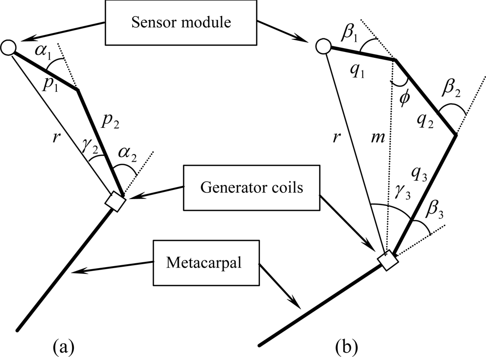
3.4. Constructing the Shape of a Finger
The objective of constructing the shape of a finger is to estimate the bending angles of the DIP, PIP, and thumb IP joints. To accomplish this, only the distance
r between the sensor module and the generator coils is involved, while the parameter
θ1 is used for estimating the bending angle of the MCP joint.
Figure 6 illustrates the relationship between the distance
r and the bending angles for the thumb and the other fingers.
The parameters
α1 and
α2 are the bending angles of the thumb IP and MCP joints, while
β1,
β2, and
β3 are the bending angles of the DIP, PIP, and MCP joints of the other fingers, respectively. The length of finger phalanges
p1,
p2,
q1,
q2, and
q3 are calculated during the calibration process. From
Figure 5 and
Figure 6, it is apparent that the bending angle of the MCP joint (
α2 and
β3) can be calculated using the following equations:
where:
The bending angle of the thumb IP joint related to the distance
r can be calculated directly using the following equation:
According to the motion constraints, the bending angles of the DIP joints of the index, middle, ring, and pinkie fingers are closely related to those of the PIP joints. With reference to
Figure 6, this relationship can be further written as:
The distance
r between the sensor module and the generator coils can be formulated as follows:
Therefore, the angle β2 can be solved from (22), and thus the bending angles of DIP, PIP, and MCP joints can be calculated.
4. Data Glove Calibration
To make the data glove easy to use, the calibration process should be made as simple and efficient as possible. This means that there is no additional device needed; as a consequence, users merely wear the data glove during the calibration process.
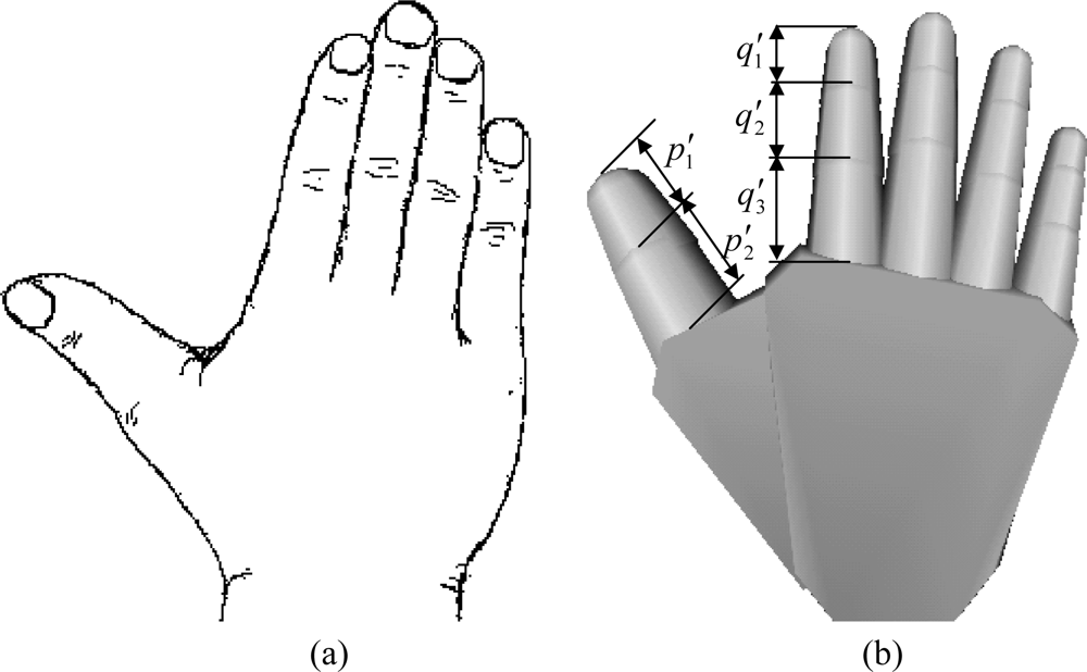
For our data glove, the calibration process consists of only one calibration gesture, as shown in
Figure 7(a). The
Emf signals produced by each sensor module and sensor coil are measured and stored into memory for further processing. When performing the calibration, the bending angle for each finger joint is equal to zero; accordingly, the parameters
θ1 and
r will be equal to:
Then the parameters
p1,
p2,
q1,
q2, and
q3 can be calculated based on the proportional length of the finger phalanges from the virtual hand as
Figure 7(b) shows. The equations of those parameters can be summarized as follows:
In this calibration process, the first generator coil of the middle finger is also used as the sensor coil for measuring the parameters of the abduction angles. When a user is making the calibration gesture, the normal vectors of the sensor and generator coils will parallel such that the orientation parameters can be written as:
The parameters of the abduction angle, that is, the distances between the sensor and generator coils, can be solved by substituting (25) into (6), which are stated in the following:
6. Realization of the Data Glove System
The data glove we have developed applies generator coils to generate electromagnetic signals. The sensor coil and sensor modules arranged on the metacarpal of the middle finger and fingertips, respectively, sense the electromagnetic signals and then measure the generated
Emf signals. Based on the measured
Emf signals, the abduction angles and fingertip positions of the hand are calculated using the derived equations as formulated in Section 3. Since ten generator coils are installed on the data glove, we should pay attention to the prevention of interference among them. There are three commonly used techniques for solving this problem:
Frequency division method
Each generator coil is driven by a sinusoidal waveform of different frequencies and the outputs of the sensor coil and sensor module are bandpass-filtered to get an appropriate Emf signal.
Time division method
In this technique, only one sinusoidal signal is used to drive the generator coils. To prevent interference, each generator coil is given an activation time slice and scanned on a round-robin basis. Within each time slice, the outputs of the associated sensor coil and sensor module are detected and the resulting analog streams are fed to an A/D converter.
Mix of frequency and time division method
With this method, two frequency bands of sinusoidal signals can be applied to activating the generator coils. Such generator coils are organized into five groups corresponding to each finger of the hand. Then, these five groups of generator coils are controlled by the time division method.
Both the time division and mix of frequency and time division methods are feasible for developing the prototype of our data glove, because the sinusoidal signals that drive the generator module must have similar characteristics. In this prototype, we adopt the time division method to control the generator and sensor coils. The advantage of this method is the feasibility of controlling them entirely via digital circuits. The block diagram of the data glove control system is shown in
Figure 11.
The sinusoidal generator circuit will continuously produce a sinusoidal signal that is fetched into an analog demultiplexer. The micro controller unit will generate timing and control signals for selecting an appropriate generator coil and enabling the output of the associated sensor module or sensor coil followed by a pre-amplifier to be passed to a bandpass filter by sending a control signal to an analog multiplexer. Before entering the analog multiplexer, the outputs of the pre-amplifier and sensor modules are fetched into the respective programmable-gain amplifiers for further amplification. Because we are only interested to the intensity of the
Emf signal produced by the sensor coil, a peak hold circuit is connected with the output of the bandpass filter for tracking the maximum value of the sinusoidal signal generated by the sensor coil. The output of the peak hold circuit is a DC level signal originated from the maximum
Emf signal of the sensor output. This DC level signal is then sampled by an A/D converter and stored into temporary memory in the micro controller unit. All the sensor outputs are sent to a host computer through a parallel communication port. The sensor module shown in
Figure 12 consists of two sensor coils that are perpendicular and co-centered. The two pre-amplifiers are used for signal enhancement.
In the development of this data glove, we use the 16-bit microprocessor SPCE061 with a built-in 10-bit A/D converter provided by Sunplus Technology.
Figure 13 depicts the timing diagram of the control signals.
The A/D SOC in
Figure 13 is the start of the conversion signal for the A/D converter, where
ts is the setup time required by the generator and sensor coils to produce a stable
Emf signal.
Table 5 lists the mapping pairs of the generator and sensor coils in the scanning process.
Figure 14 illustrates the sinusoidal output waveform from the analog demultiplexer for a generator coil as well as the sinusoidal output waveform of the associated sensor coil with the time division method. To get a clear inspection on the sinusoidal waveform, in this demonstration, only two generator coils are scanned on a round-robin basis.
7. Conclusions
In this paper, the development of a data glove with fingertip tracking technology based on magnetic induction has been presented. This data glove has the ability of measuring 17 DOF by reconstructing the shape of the fingers after the positions and orientations of the fingertips have been estimated. By tracking the fingertips of the hand, the object manipulation tasks in a virtual environment or teleoperation system can be controlled more precisely, since in most of grasping processes, fingertips are the foremost areas that reach the surface of an object. To track the fingertips, we use five sensor modules and one sensor coil that are attached on the fingertips and metacarpal of the middle finger of a hand. The sensors and generators constructed with small magnetic induction coils are called the sensor coils and generator coils of the data glove, respectively. The sensor module consists of two sensor coils that are perpendicular and co-centered. All of these sensor and generator coils are placed on the fingertips and metacarpal positions of the hand, so that there is no direct contact point between the sensors and the finger joints. It means that the data glove sensors do not change their shapes when the fingers are bending. Thus, not only the quality of measurement is greatly improved, but also the lifetime of the sensors is greatly prolonged.
To facilitate the action of the data glove, the sensor module can be constructed entirely by hardware using the currently available semiconductor technology, so that the power
Emf signal is calculated directly using hardware as shown in
Figure 15. Thus, more accurate results can be gained due to a higher SNR of the signal in the transmission wire.
The motion constraints applicable to simplifying the development of the data glove are also investigated. They are classified into three categories: intrafinger constraints, angle range constraints, and one-axis constraints. With the intrafinger constraints, the shape of a finger can be constructed based on the measured fingertip position, and hence, the DIP and PIP bending angles can be calculated. The angle range and one-axis constraints are devoted to simplify the Emf equations, so that the fingertip position and orientation can be easily calculated. For the convenience of using the data glove, we also propose a simple and efficient calibration process that comprises only one calibration gesture.
The theoretical formulation of the fingertip position and orientation, and the abduction angles of the finger joints as well as the calibration equations are derived directly from the positions and orientations of the generator and sensor coils on the data glove. Beside this, the circuit block diagram and the construction of the data glove system are described and realized. To prevent the interference among the generator coils, three methods of scanning the generator and sensor coils, including the frequency division, time division, and mix of frequency and time division techniques, are also discussed. After the evaluation, we adopted the time division method to control the generator and sensor coils in developing the prototype of our data glove. The advantage of this method is the feasibility of controlling them entirely via digital circuits. Another superiority of this data glove compared to use the Pohemus motion tracking system [
21] is that the distances between the generator coils and sensor modules are close enough such that only small power of electromagnetic radiation is needed, and the interference of a metallic object with the distance greater than 20 cm from the data glove can be ignored. But the supporting of the Pohemus motion tracking system for detecting the positions of hands in a 3D environment becomes significantly important when the complete movements of hands are required. So far, the experimental results of the sensors performing linear movement and bending angle measurements are very satisfactory. It reveals that our data glove can act as an practical man-machine interface.


