Abstract
With the rapid development of wind power generation, the inertial response of wind turbines (WTs) has become a topic of wide concern recently, due to its influence on grid frequency dynamics and stability. This paper proposes and defines the inner potential to summarize and understand the inertia control methods and inertial response of type-3 and type-4 WTs, which is analogous to typical synchronous generators (SGs), to make it more easy to understand by system operators and engineers with a traditional power system background. The dynamics of the defined inner potential of the wind turbine without any inertia control is different from SGs, thus the electromechanical inertia is completely hidden. The rapid power control loop and synchronization control loop are the major reasons that the WT’s inertial response is disenabled. On the basis of the defined inner potential’s dynamic, the existing inertia control method for WTs are reviewed and summarized as three approaches, i.e., optimizing the power control or synchronization control or both. At last, the main challenges and issues of these inertia controls are attempted to explain and address.
1. Introduction
The installed wind power generation capacity is growing rapidly. For example, in 2015 the added capacity of wind power generation was 30.5 GW [1,2] and the total capacity reached 145.1 GW in China. 186.3 TWh of electricity is generated [1,2], representing 3.3% of the state’s total electricity consumption [1,2]. Wind power has thus become the third largest power source in China. It is forecast that the wind capacity will reach 250 GW by 2020 in China as part of the government’s pledge [3].
Modern wind farms are mostly equipped with variable-speed wind turbines (WTs) [3,4,5,6] due to their excellent performance. Based on power-electronic technology, the variable-speed WTs decouples the WT’s rotor from the grid in order to obtain good control and regulation performance, while the electromechanical inertia is also simultaneously hidden [7]. With more and more wind power generation integrated into the grid via power-electronic interfaces, the inertia losses are of wide concern and much-maligned [7,8]. The inertial response of devices is the most important feature of frequency response [9], which is effective to reduce the change rate of grid frequency. With the reduction of inertia, the change rate and nadir of grid frequency are increased, which is harmful for the frequency stability and the operations of grid-connected devices [10].
In the last decades, many inertia control methods were developed for type-3 [11] and type-4 [12] wind turbines (WTs) to enable the inertial response of WTs. For example, the df/dt [13] is added into WT’s torque reference to respond and improve grid frequency change rate (df/dt), which is a direct improved control method to enable the inertial response. Moreover the virtual synchronous generator [14] was initially proposed to provide inertia response features in voltage source converters (VSCs) and to provide inertial response. Wang et al. employed the virtual synchronous control in DFIG-based WTs to enable their inertial response [15,16].
Due to the highly controllable characteristics, the inertia control methods for wind turbines are numerous and complicated. As far as the authors know, some reviews [9,17,18,19,20,21,22,23] have roundly summarized and analyzed the existing inertia control methods for wind turbines. These reviews are implemented from the perspective of the control of the wind turbine and concern many control details, which are very helpful for realizing the inertia control design of the wind turbine and evaluating the research status, but the control system of wind turbines with inertia control is so complex and different from the traditional synchronous generator that it cannot easily be understand by system operators and engineers with a background in traditional power systems (they are typically very acquainted with the dynamic of the traditional synchronous generator). Thus, a survey is necessary to summarize the dynamics of the wind turbine with existing inertia control methods and relate the dynamics of the wind turbine with the traditional synchronous so generator system operators and engineers with a background in traditional power systems can more easily understand and recognize wind turbines with inertia control, which will be the main contribution of this paper. This paper presents a review of the inertia control methods to enable the inertial response of WTs from the perspective of the WT’s defined inner potential and similar to the rotor swing of the synchronous generator, which is the major novelty of this paper.
The rest of this paper is organized as follows: firstly, based on the general control and simplified model, the basic concept and dynamic of WT’s defined inner potential are presented referring to the typical synchronous generators (SGs). In particular the hidden inertial response of WTs is explained and illustrated. Moreover, on the basis of the defined inner potential, the existing inertia controls for WTs are summarized and unified as three kinds for convenient and in depth understanding, i.e., modifying the dynamic of synchronization control or power control or both in WTs, respectively. Finally, an attempt is made to address and explain the main issues and challenges.
2. General Concept of the Defined Inner Potential
Any grid-connected device can be represented as a rotating voltage vector, i.e., an inner potential. The device’s dynamic characteristics can be described using the dynamic motion of the inner potential’s phase and magnitude. In the grid, lots of devices are integrated together, in other words, many inner potential vectors are coupled through the network. The inner potential phase and magnitude motion are driven by the input and output active (or torque) and reactive powers of the devices. The inertia of the inner potential’s phase motion reflects the inertia characteristics of the device. The well-known synchronous generator (SG) [10] is taken as an example to illustrate the concept of the inner potential vector.
The SG can be regarded as a rotating voltage vector, i.e., the defined inner potential (E) as seen in Figure 1.
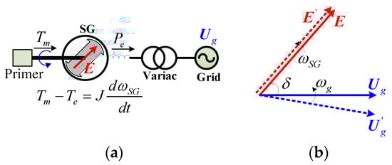
Figure 1.
Schematic diagram of SGs’ inner potential. (a) Electric diagram; (b) Phasor diagram.
The defined inner potential is rotating along with the SG’s rotor, whose phase motion abides by the rotor swing motion. The magnitude of the SG’s inner potential is regulated by the excited system. The inertia of the inner potential’s phase motion is the rotor rotational inertia:
The inertial response can be represented using the defined inner potential. Once the disturbance occurs in grid, the grid voltage jumps from to . Not considering the action of excitation system, the inner potential (E) maintain original movement state (E’) due to the intrinsic rotating inertia (J) of rotor as shown in Figure 1b. The power angle immediately and dynamically increases to provide the synchronized power for grid support and its own re-synchronization. In this process, the inertia, i.e., the kinetic energy stored in the rotor of SGs, is spontaneously used for the dynamic energy support of the grid frequency. This paper summarizes and compares the main existing inertia controls of the wind turbine.
3. Representative Control and Simplified Model of Type-3 and Type-4 Wind Turbines
3.1. WT’s General Controls
The general control block diagrams of type-3 and type-4 variable speed wind turbines (WTs) [11,12] are shown as Figure 2a,b. General control of WTs usually includes two main part, i.e., mechanical and electrical parts. The mechanical part mainly includes the turbine control and speed control. The turbine control aims to control the pitch angle to regulate the mechanical power captured from the wind. The speed control is to control the rotation speed by regulating the electromagnetic torque. The mechanical part control of type-3 and type-4 WTs is the same as in Figure 2a.
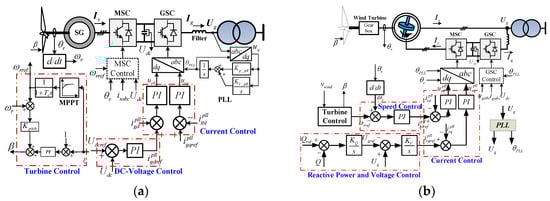
Figure 2.
Basic control block diagram of WTs. (a) Type-4 WTs; (b) Type-3 WTs.
For type-4 WTs, a back-to-back full-capacity converter is used completely to decouple the generator with grid as in Figure 2a, which is called machine side converter (MSC) and grid side converter (GSC), respectively. While type-3 WTs are integrated into the grid through both back-to-back part-capacity converters and the generator stator as in Figure 2b. The main function of GSC is usually to control the DC-link voltage through cascaded DC-voltage control and current control. The MSC is to regulate the electromagnetic torque. A phase-locked loop (PLL) is used as a synchronization and measurement unit to synchronize WTs with the grid.
3.2. WT’s Simplified Models
Neglecting the dynamics of current control and filters, the dq-axis actual grid (,) and rotor currents (,) are equal to the current references (, and ,) in the PLL’s reference frame, respectively, viz.:
Not considering the turbine control with slow electromechanical dynamics, the models of WTs can be further deduced and simplified as seen in Figure 3a,b. For type-4 WTs, the DC voltage controller is equivalent to a rapid power control, which aims to rapidly maintain the output electromagnetic power constant in the DC capacitor and equal to the electromagnetic power from generators during any grid disturbance.
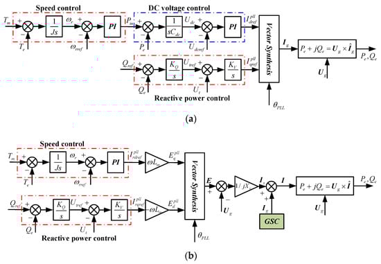
Figure 3.
Simplified control block diagram of WTs. (a) Type-4 WTs; (b) Type-3 WTs (Xs is equivalent impedance between inner potential and grid voltage).
While for type-3 WTs, the grid side converter is similar to type-4 WTs, which is simply represented by GSC in Figure 3b. The dq-axis current references of the machine side converter are regulated according to the rotation speed and reactive power control. The dq-axis rotor currents can produce an electromotive force () through the mutual inductance (Lm) of DFIG. The electromotive force will produce stator current (Is) interacting with grid voltage (Ug).
4. Defined Inner Potential of the Wind Turbine
From the perspective of the power grid, the variable-speed WT can be regarded as an defined inner potential coupling with the grid through an equivalent impedance, but the movements of the inner potential are much more complicated than SGs because it is the result of the sequential action of a series of multi-time-scale power controllers in WTs.
4.1. Defined Inner Potential of Type-4 WTs
The defined inner potential of type-4 WTs can be defined as in Equations (3) and Figure 4:
where E is the inner potential vector. θe and E are the phase and magnitude of the defined inner potential under the reference frame rotating at ω0. Ed, Eq, Ugd, Ugq, Id and Iq are the dq-axis components of defined inner potential, grid voltage and current, respectively. Xf is the impedance of filter.
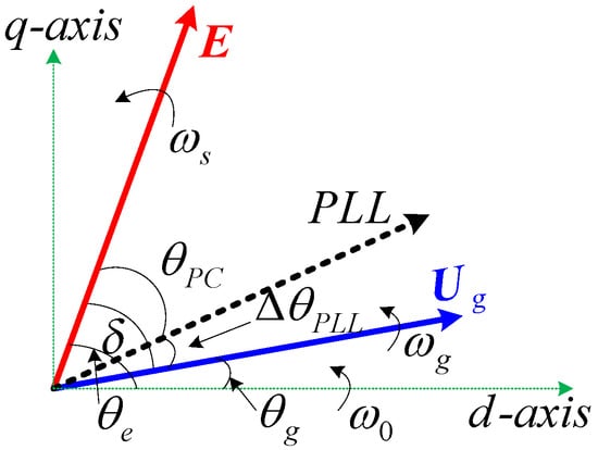
Figure 4.
Defined inner potential of WTs.
The phase of inner potential is mainly constituted by the PLL’s phase (θPLL) and the phase (θPC) decided by a series of power controls as Figure 4:
where and are controlled by the dq-axis currents components, which are decided by active and reactive power control. θPC is the phase angle between the defined inner potential and PLL’s phasor which is decided by power control.
Under steady state conditions, the inner potential is rotating synchronously with the grid voltage. The phase difference, i.e., power angle (δ) between inner potential and grid is constant, thus the output power is stable and constant. The output electromagnetic power can be expressed as:
where δ is power angle, and θg is the phase of grid voltage.
4.2. Defined Inner Potential of Type-3 WTs
The defined inner potential of type-3 WTs should be synthesized by the generators’ stator side and GSC. The dynamics of GSC are similar with type-4 WTs and GSC’s capacity is much smaller than the generators’ stator side. For simplified analysis, the effect of GSC can be neglected in the inertial voltage of type-3 WTs.
The defined inner potential of type-3 WT is similarly defined as in Figure 4:
where Xs is the equivalent impedance between the defined inner potential and grid. Isd and Isq are the dq-axis current components of WT’s stator.
The phase of inner potential is mainly constituted by the PLL’s phase (θPLL) and the phase (θPC) decided by a series of power controls as in Figure 4:
where and are proportional to the dq-asix rotor currents (, ), which are decided by power or torque regulations in WT’s speed control.
The output active power and power angle can be expressed as:
The power angle can also express as (9), whose dynamic is also decided by both PLL’s phase error and power controls. The phasor diagram of defined inner potential is also plotted as in Figure 4:
4.3. Inertial Response Analysis of WTs
WTs have enough kinetic energy stored in the turbine rotor for inertial response which is the basis for inertial response, thus additional power storage is usually unnecessary, but due to the fact the phase motion dynamics of WT’s defined inner potential is different from typical SGs, the electromechanical inertia of WTs is fully hidden, thus there is no inertial response from typical type-3 and type-4 WTs on the electromechanical time scale.
For type-3 WTs, the phase motion diagram is further deduced in Figure 5a. The power angle is collectively decided by speed control (θPC) and PLL (ΔθPLL). In typical type-3 WTs, the PLL usually has enough bandwidth to follow the grid’s electromechanical dynamics and to isolate the electromechanical dynamics from WTs. Due to rapid PLL’s decoupling, the electromechanical disturbance from the grid and the WT’s electromechanical motion are completely separated, which is the main reason for the inertia of type-3 WTs being hidden.
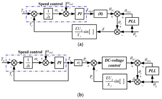
Figure 5.
Phase dynamic of defined inner potential of type-3 and type-4 WTs. (a) Type-3 WTs; (b) Type-4 WTs.
For type-4 WTs, the phase motion diagram is further simplified as in Figure 5b. The defined inner potentials of type-3 and type-4 WTs have a similar form of expression. The main difference is that there is an equivalent rapid power control loop generated by the DC voltage control. The equivalent power control loop directly regulates the partial phase’s dynamic (θPC) of the inner potential and roughly forms a control close loop in power angle as seen in Figure 5b. Usually the DC voltage control has a control bandwidth of about 10-Hz, which can follow the electromechanical dynamic of the grid and keep the output power constant when any electromechanical disturbance occurs in grid. Thus the electromechanical dynamic of type-4 WTs is separated from the grid not only by rapid PLL but also by the equivalent power control loop in the DC voltage. These are the main reasons for the inertia of type-4 WTs being hidden.
5. Main Inertial Response Release Methods
Based on the defined inner potential of WTs and its dynamic analysis, the rapid PLL and power control loops completely separate the swing motion of a WT’s rotor from the grid and hide the rotor inertia of WTs, which makes the defined inner potential of WTs have very small inertia features and nearly no inertial response. Thus the phase dynamics of the defined inner potential should be improved for the inertial response of WTs. To enable the inertial response of WTs, the swing equation of WT’s rotors needs to be coupled with the grid to feel the grid disturbance on the electromechanical time scale. All the existing inertia control methods for WTs can be classified as modifying power control, optimizing the dynamic response of synchronization control, or both.
5.1. Attaching Supplementary Signal into Power Control
The most common and representative way for WTs to make inertial response available is to provide a supplementary signal associated with the detected grid frequency variations or its differential to the torque/power or speed reference value to be tracked as in Figure 6a, which is suitable for both type-3 and type-4 WTs [24,25,26,27,28,29,30,31,32,33,34,35].
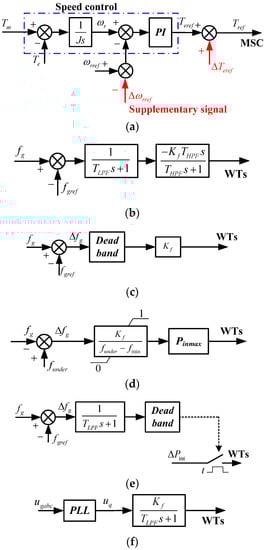
Figure 6.
Several inertia controls of WTs based on supplementary signals. (Kf is the gain, TLPF and THPF are the time constants of filters, fg and fgref are the measured and nominal grid frequency). (a) Overall control block of WT’s inertia control based on supplementary signal; (b) df/dt method; (c) Δf method. (d) Enercon IE (funder is the set value of under-frequency event. fmin is the minimum grid frequency, Pinmax is the maximum power increase of WTs); (e) Frequency deviation trigger (ΔPint is the increased power); (f) PLL’s error.
For example, the original torque controller is modified by adding a signal corresponding to ΔT = 2H(df/dt) to the set torque. As the grid frequency drops, the modified set point torque is increased slowing the rotor and extracting the stored kinetic energy. In order to remove the measurement noise, and minimise the impact of the supplementary control on mechanical drive train loads, the rate of change of power injection is usually modified by adding a first-order filter after the df/dt input [24].
GE’s WindINERTIATM feature provides an inertial response capability for WTs by introducing a washout filter to temporarily increase the output power [25] as shown in Figure 6b. A washout filter is also used in [26] to make WTs only act in a transient way using the stored kinetic energy. Reference [27] proposes another different control scheme to create inertial response, that is, the additional torque setpoint is based on the absolutely deviation of the frequency from the nominal value, i.e., ΔT = Kf (fg − fgref) as Figure 6c. ENERCON IE is implemented by using the frequency deviation relative to the trigger level that responds to a drop in grid frequency by temporarily increasing active power beyond the available power from the wind [28] as seen in Figure 6d. Similarly, [29] develops a control scheme to improve the frequency response capability of type-4 WTs by a combination of the abovementioned two kinds of terms associated with frequency differential and its absolute deviation.
Besides, there are also some other methods to improve WTs’ inertial response capability. An approach which utilises slip to supply the short-term frequency support is discussed in [30]. In [31] a method to provide the dynamic frequency support through properly altering the maximum power point tracking (MPPT) curve coefficient, which is a function of grid frequency deviation, is proposed. In [32,33] the phase-locked error of the optimized PLL is introduced to modify the speed set point for type-4 WTs to provide inertial support as seen in Figure 6f. An algorithm to extract the maximum kinetic energy without stalling WT is proposed in [34], in which the electric torque is increased step-wisely and then ramped down considering the governor time constant. Similarly, Senvion’s (formally Repower) MM82 2MW DFIG-based WTs also increase the active power independently of the system frequency deviation as Figure 6e, i.e., a step function operating at a specific threshold [35]. The publically reported inertia controls of several WTs manufacturers are presented in Table 1.

Table 1.
The existing industrial inertia control of main WTs manufacturers.
All in all, though the implementations listed above have some differences, they are essentially the same. They all emulate the inertial response by changing the response behaviours of the commonly designed power control system when triggered by frequency events, by altering the reference value of either the active power/torque or speed. More essentially speaking, they finally change the power angle dynamic behaviours of WT’s defined inner potential through some modifications in the power control, i.e., modifying the dynamic of θPC.
5.2. Optimizing the Dynamic Response of Synchronization Control
As a measurement and synchronization unit, the performance requirement for PLL currently is as fast and accurate as possible to capture the phase angle of grid voltage. As a result, the electromechanical inertia of WTs is completely hidden without any response to the electromechanical disturbance in grid. In order to release the inertial response of WTs, the dynamic response of PLL can be optimized and PLL’s dynamic is utilized to enable the inertial response [36,37].
For type-3 WTs, the partial phase of WT’s defined inner potential (θPC) is decided by the speed controller with electromechanical dynamic. The power angle is equal to the sum of θPC and PLL’s phase error (ΔθPLL). Once the bandwidth of PLL is reduced and its dynamic is slow down, the power angle will obviously enlarge (from to ) with the electromechanical disturbance in grid as in Figure 7a. As a result, the spontaneous and natural inertial response of type-3 WTs is enabled. The inertia constant of the defined inner potential is related to PLL’s bandwidth [36,37].
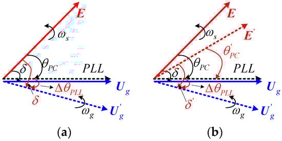
Figure 7.
Phasor diagram with reducing the control bandwidth of PLL. (a) Type-3 WTs; (b) Type-4 WTs.
While for type-4 WTs, only reducing the dynamic response of PLL cannot enable its inertial response due to the effect of equivalent rapid power control loop in the DC voltage. The slow dynamic response of PLL and the PLL’s error are produced with reduced bandwidth during electromechanical disturbance, but the equivalent power control in the DC voltage is still able to rapidly regulate the dq-axis inner potential components under PLL’s frame ( and ) through altering the dq-axis current reference. The phase θPC is regulated to to maintain the power angle and output power constant as Figure 7b, viz. δ = δ′. Thus the electromechanical rotating inertia of type-4 WTs is still hidden when the PLL dynamics slow down.
Through optimizing the PLL’s dynamic response, the inertial response of type-3 WTs can be enabled. Based on this method, the control structure of type-3 WTs is not required any modifications and changes, and only PLL’s parameters need to be regulated and optimized. The inertial response released by this method is spontaneous, passive and natural. It should be pointed out that the inertial response is directly related the disturbance in the grid without any closed-loop control, which can respond faster but may arouse an over-inertial response to threaten the safety and stability of WT’s operations.
5.3. Virtual Synchronous Control
Virtual synchronous control was developed to emulate SGs to embed inertial response in grid-connected voltage source converters (VSCs) [38,39,40,41,42,43,44,45,46,47,48,49,50,51,52,53] as virtual synchronous generators/machines recently, which has been discussed and studied in energy storage [39], Statcom [40], VSC-HVDC [41,42,43,44], distributed generation [45,46,47], microgrids [48], etc. Essentially the virtual synchronous control regulates the magnitude and phase of VSC’s output voltage according to active and reactive power errors as Figure 8. Zhong et al. proposed a virtual synchronous control method as synchronverter by implementing the whole equation of SGs to emulate the full dynamics of SGs in VSCs [49,50]. Moreover, Ise et al. employed a second-order SG’s rotor swing equation to regulate the required voltage according to power errors and then an inner voltage loop is used to produce the required voltage, which can feature inertial response in VSCs [51]. In addition, a linear power-damping and synchronizing controller was used to emulate SG’s dynamic performance in VSCs by Mohamed et al. [52,53], while the most common and representative virtual synchronous control methods are developed to enable the inertial of type-3 and type-4 WTs in [54,55].
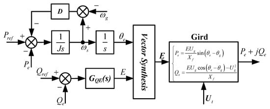
Figure 8.
Typical virtual synchronous control.
The virtual synchronous control is implemented in type-3 WTs to motivate the inertial response [15,16]. The most representative is VSynC. VSynC features a well-known synchronization mechanism of SGs in the rotor side converter of type-3 WTs relying on active power. In VSynC, the second-order motion equation is employed to control the excited voltage from the machine side converter according to the power output by the WT’s stator. The phase dynamic of the WT’s defined inner potential is constituted by the second-order controller of VSynC and WT’s rotor swing. As a result, the inertial response of type-3 WTs is able to be provided spontaneously and the VSynC can enhance the operation stability of WTs integrated into weak grids.
For type-4 WTs , meanwhile, if only the grid side converter is modified by employing the virtual synchronous control, the inertial response cannot be provided to support the electromechanical frequency dynamics of the grid due to the limitation of rapid power control in the DC-link voltage. Thus in order to release rotor’s energy for dynamic support of frequency, the functions of grid-side and machine-side converters are exchanged, i.e., the DC-voltage is controlled by the machine side converter and the grid side converter is used to regulate the electromagnetic torque of generators as illustrated in Figure 9b. Through the exchange, the rapid power control loop (DC voltage control) is cut from grid as an inner power loop with the connection to grid and WT’s rotor is able to directly relate to the grid and to respond to grid disturbances on the electromechanical time scale. As a result the kinetic energy in the rotor is released and the inertial response can be provided spontaneously and naturally with the electromechanical disturbances in the grid.
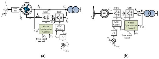
Figure 9.
Enable inertial response of type-3 and type-4 WTs based on virtual synchronous control. (a) type-3 WT; (b) type-4 WT.
The virtual synchronous control alters the synchronization and power control method of WTs together. Due to the removal of the PLL, WTs can get more stability in weak grids based on the virtual synchronous control. The virtual-synchronous-control-based inertial response is spontaneous and natural without feedback or closed loop control, which can provide excellent dynamic support capacity for the grid frequency but overlarge grid disturbances may arouse a quite sharp inertial response that can affect WT’s safety and stability.
5.4. Comparisons Between the Inertial Response of Different Control Methods
For comparing the inertial response of the inertia control methods presented in Section 5, simulations were implemented in a brief test power system by Simulink/Matlab. The test power system is established by two synchronous generators, and an aggregation model of a wind farm with 200 wind turbines driven by DFIG is established as in Figure 10.
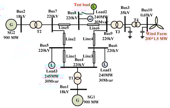
Figure 10.
The power system for testing the inertial response of the WT.
The three representative inertia control methods i.e., attaching df/dt into power control [22], slowing down the PLL [33] and virtual synchronous control [50] are tested, respectively. The three aspects of the dynamic response characteristics are briefly evaluated, i.e., the inertial response, the corresponding grid frequency and the oscillation of the WT’s rotor as seen in Figure 11.
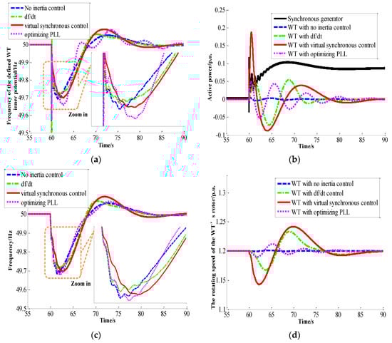
Figure 11.
Simulation results of the WT’s inertial response, the grid frequency and the rotating speed of the WT’s rotor. (a) The dynamic response of the wind turbine’s defined inner potential with different inertia control methods; (b) The inertial response of the wind turbine with different inertia control methods; (c) The grid frequency with different inertia control methods; (d) The rotating speed of the WT’s rotor with different inertia control methods.
(1) The defined inner potential of the wind turbine
The dynamic of the defined inner potential of the wind turbine with and without inertia control is presented in Figure 11a. Under steady state, the defined inner potential is synchronized with grid. Under the power disturbance in grid, without the inertia control, the frequency of the defined inner potential of the wind turbine declines faster than the wind turbine with the inertia control. With the inertia control, the frequency of the defined inner potential will change at a lower rate.
(2) The inertial responses of the wind turbine
The inertial responses of the wind turbine with different inertia control methods are presented in Figure 11b. Without the inertia control, the wind turbine will nearly not respond to any power disturbances in the grid as shown in Figure 11b. With different inertia control methods, the dynamic response is different. The inertia control methods based on optimizing the PLL and the virtual synchronous control can immediately provide active power support to the grid nearly without any time delay, whereas the active power support from the df/dt method is delayed due to the detection of the grid frequency and its derivative. Moreover, the power oscillation and control parameters of the methods with slowing down the PLL and the df/dt are much more serious and more difficult to adjust than the virtual synchronous control.
(3) The corresponding grid frequency
The corresponding grid frequency using the wind turbine with and without inertial response are presented in Figure 11c. Without the inertial response of the wind turbine, the grid frequency declines at a higher change rate as shown in Figure 11c. With the inertia control, the WT can provide additional active power support when a power disturbance occurs in the grid and the corresponding change rate of the grid frequency is reduced.
(4) The swing of the WT’s rotor
The rotor swing of the wind turbine with the inertial response becomes much more serious, which challenges the design and safe operation of the wind turbine as seen in Figure 11d. After the power disturbance, the wind turbine with these inertia control methods will intake the power from the grid as shown in Figure 11b for the recovery of their rotor speed as shown in Figure 11d, which may arouse the second decline of the grid frequency as in Figure 11c.
(5) Summary of the major characteristics of different inertia control methods
The main characteristics of these inertia control are compared and presented in Table 2. The methods that optimize the PLL and virtual synchronous control do not require one to measure the grid frequency and thus they can provide no-delay inertial response to support the grid frequency, but they may give rise to an excessive inertial response of the wind turbine. Other methods must measure the grid frequency and provide the inertial response with the feedback control loop. Moreover, the implementation of the virtual synchronous control is more complicated than others, because it should replace the traditional control structure in the DFIG. The method optimizing the PLL is implemented very easily just through adjusting its parameters without any modifications.
Table 2.
Major characteristic of the wind turbine’s main inertia control.
6. Key Challenges and Future Research
Enabling the inertial response of WTs will pose new issue and challenges in the WT itself and even affect the control of the whole power system. Here, some issues and challenges are presented and briefly explained.
6.1. Assessing Mechanical Loading and Stress of WTs
During the inertial response, the electromechanical motion of WT’s rotor is coupled with the grid. The WT blades, drive chain, etc. will suffer from some power and stress shock during frequent grid disturbances. The mechanical loading and stress should be analysed and studied to guarantee WT’s safety and stability for inertial response.
6.2. Frequency Secondary Decline
The inertia control of the wind turbine should be coordinated with the turbine control to avoid the inertial response from dragging down the turbine control of the wind turbine itself. With the increasing penetration of wind power generation, the issue of the frequency secondary decline should be considered, which may be settled through the coordination with the turbine control and the primary frequency regulation of the whole power system.
6.3. Unified Description of WT’s Inertial Response Characteristics and its Effect on Grid Frequency Dynamic
When WT’s inertial response is enabled, the basic characteristics of the inertial response based on different inertia control methods should be evaluated, described and distinguished. WT’s inertial responses need to be compared with the one of typical SGs. Moreover the relation and interaction between the inertial response featured by different methods and grid frequency dynamic should be further analysed and studied.
6.4. Operating Under Grid Faults
The action of the control to feature inertia in WTs needs to be further studied during grid faults. The fault current is analysed and limited especially for virtual synchronous control methods. The interaction between the inertia control and typical fault ride through controls should be analysed and coordinated.
6.5. Inertial Responses from Multi-WTs
The relations and interaction between the inertial responses from multi-WTs should be studied and evaluated. The inertial response should be coordinated to avoid the clash and competition between WT-to-WT, wind farm to wind farm, wind farms to SGs, especially when adding supplementary signal methods. The inertia control parameters should be analysed and optimized.
6.6. Grid Codes
On the basis of the key basic characteristics of inertial response and its effect on grid frequency, the unified grid code for WT’s inertial response needs to be formulated and revised to standardize WT’s inertial response, which is helpful for the development of wind power generation and further promotes the penetration of wind power in the grid.
7. Conclusions
This paper develops the WT’s equivalent inertial voltage. On the basis of the basic understanding, this paper reviews and summarizes the control methods to enable both type-3 and type-4 WT’s inertial response from the view of the equivalent inertial voltage. The rapid synchronization control by PLL and rapid power control loop by DC voltage control fully isolate the rotor swing dynamics of the defined inner potential from grid, which are the main reasons for WT’s inertia being hidden.
These existing inertia control methods are mainly classified into three kinds, i.e., supplementary signals for the power control, optimizing the synchronization control’s dynamic and virtual synchronous control. These control methods modify the phase dynamic characteristics of WT’s defined inner potential through improving synchronization control or power control or both, respectively. The supplementary signal and virtual synchronous control are effective for both type-3 and type-4 WTs. Optimizing PLL’s dynamics is effective to enable the inertial response of type-3 WTs through improving the dynamics of synchronization control. The supplementary signal method is an active feedback control method by improving the dynamics of power control.
The inertial response from the supplementary signal method is active and controllable but delays are inevitably introduced, while for the optimization of PLL’s dynamics and virtual synchronous control methods, the inertial response is spontaneous and passive nearly without any time delays but the inertial response strength is not fully controllable, which may give rise to undue inertial responses.
Acknowledgments
This work is supported by National Key Research and Development Program under Grant 2016YFB0900104, National Natural Science Fund for Excellent Young Scholars under Grant 51322704, and National Science Foundation of China (51361136703).
Author Contributions
Lei Shang edits and revises the main body of this paper; Jiabing Hu and Xiaoming Yuan propose the general concept of the inner potential; Yongning Chi implements the simulation of this paper and gives many advices for revisions. Many revisions are made by all the authors.
Conflicts of Interest
The authors declare no conflict of interest.
References
- China Wind Power Blows Past EU—Global Wind Statistics Release. Available online: http://www.gwec.net/china-wind-power-blows-past-eu-global-wind-statistics-release/ (accessed on 25 September 2016).
- China’s New Wind Power Capacity Rises 60%, Hits Record High. Available online: http://www.chinadaily.com.cn/business/2016–02/03/content_23368847.htm (accessed on 3 February 2016).
- Wind Power in China. Available online: https://en.wikipedia.org/wiki/Wind_power_in_China#cite_note-7 (accessed on 13 December 2016).
- Li, H.; Chen, Z. Overview of different wind generator systems and their comparisons. IET Renew. Power Gener. 2008, 2, 123–138. [Google Scholar] [CrossRef]
- Müller, S.; Deicke, M.; De Doncker, R.W. Doubly fed induction generator systems for wind turbines. IEEE Mag. Ind. Appl. 2002, 8, 26–33. [Google Scholar] [CrossRef]
- Bhende, C.N.; Mishra, S.; Malla, S.G. Permanent magnet synchronous generator-based standalone wind energy supply system. IEEE Trans. Sustain. Energy 2011, 2, 361–373. [Google Scholar] [CrossRef]
- Björnstedt, J. Integration of Non-Synchronous Generation: Frequency Dynamics. Ph.D. Thesis, Lund University, Lund, Sweden, 2012. [Google Scholar]
- Muljadi, E.; Gevorgian, V.; Singh, M.; Santoso, S. Understanding inertial and frequency response of wind power plants. In Proceedings of the Power Electronics and Machines in Wind Applications, Denver, CO, USA, 16–18 July 2012; pp. 1–8.
- Rebours, Y.G.; Kirschen, D.S.; Trotignon, M.; Rossignol, S. A survey of frequency and voltage control ancillary services-part I technical features. IEEE Trans. Power Syst. 2007, 22, 350–357. [Google Scholar] [CrossRef]
- Kundur, P. Control of active and reactive power. In Power System Stability and Control, 1st ed.; McGrawHill Press: New York, NY, USA, 1994; pp. 582–591. [Google Scholar]
- Proposed Changes to the WECC WT3 Generic Model for Type 3 Wind Turbine Generators. Available online: https://www.wecc.biz/Reliability/WECC-Type-3-Wind-Turbine-Generator-Model-Phase-II-012314.pdf (accessed on 26 March 2016).
- Proposed Changes to the WECC WT4 Generic Model for Type 4 Wind Turbine. Available online: https://www.wecc.biz/Reliability/Report_on_WT4_Model_Description_PP012313.pdf (accessed on 29 August 2016).
- Sun, Y.; Zhang, Z.; Li, G.; Lin, J. Review on frequency control of power systems with wind power penetration. In Proceedings of the International Conference on Power System Technology, Hangzhou, China, 24–28 October 2010; pp. 1–8.
- Vu, T.; Visscher, K.; Diaz, J.; Karapanos, V.; Woyte, A.; Albu, M.; Bozelie, J.; Loix, T.; Federenciuc, T. Virtual synchronous generator: An element of future grids. In Proceedings of the IEEE PES Innovative Smart Grid Technologies Conference Europe, Gothenburg, Sweden, 11–13 October 2010; pp. 1–7.
- Wang, S.; Hu, J.; Yuan, X. DFIG-based wind turbines with virtual synchronous control: Inertia support in weak grid. In Proceedings of the Power and Energy Society General Meeting, Denver, CO, USA, 26–30 July 2012; pp. 1–8.
- Wang, S.; Hu, J.; Yuan, X. On Inertial Dynamics of Virtual-Synchronous-Controlled DFIG-Based Wind Turbines. IEEE Trans. Energy Convers. 2015, 30, 1691–1702. [Google Scholar]
- Xue, Y.; Tai, N. Review of contribution to frequency control through variable speed wind turbine. Renew. Energy 2011, 36, 1671–1677. [Google Scholar]
- D’Arcoa, S.; Suul, J.A.; Fosso, O.B. A virtual synchronous machine implementation for distributed control of power converters in SmartGrids. Electr. Power Energy Syst. 2015, 122, 180–197. [Google Scholar] [CrossRef]
- Wu, Y.; Shu, W.; Hsieh, T.; Lee, T. Review of inertial control methods for DFIG-based wind turbines. Int. J. Electr. Energy 2015, 3, 174–178. [Google Scholar]
- Sun, L.; Yuan, X.; Hu, J.; He, W. Inertial control methods of variable-speed wind turbine: Comparative studies. In Proceedings of the IEEE Power Engineer Society General Meeting, Denver, CO, USA, 26–30 July 2015; pp. 1–5.
- Sun, L.; Yuan, X.; Hu, J.; Wang, S.; Chi, Y. Modeling of type 3 wind turbine with df/dt inertia control for system frequency response study. IEEE Trans. Power Syst. 2016, 1. [Google Scholar] [CrossRef]
- Wickramasinghe, A.; Meegahapola, L.; Agalgaonkar, A.; Perera, S. Grid-tied control of variable speed wind turbines for enhanced inertial support. In Proceedings of the Australasian Universities Power Engineering Conference, Wollongong, Australia, 27–30 September 2015; pp. 1–6.
- Yu, M.; Dyśko, A.; Booth, C.D.; Roscoe, A.J.; Zhu, J. A review of control methods for providing frequency response in VSC-HVDC transmission systems. In Proceedings of the 49th International Universities Power Engineering Conference (UPEC), Cluj-Napoca, Romania, 2–5 September 2014; pp. 1–6.
- Ekanayake, J.; Jenkins, N. Comparison of the response of doubly fed and fixed-speed induction generator wind turbines to changes in network frequency. IEEE Trans. Energy Convers. 2004, 19, 800–802. [Google Scholar] [CrossRef]
- Clark, K.; Miller, N.W.; Sanchez-Gasca, J.J. Modeling of GE Wind Turbine Generators for Grid Studies; GE-Power Systems Energy Consulting, General Electric International, Inc.: Schenectady, NY, USA, 2008. [Google Scholar]
- Mauricio, J.M.; Marano, A.; Gomez-Exposito, A.; Martinez-Ramos, J.L. Frequency regulation contribution through variable-speed wind energy conversion systems. IEEE Trans. Power Syst. 2009, 24, 173–180. [Google Scholar] [CrossRef]
- Morren, J.; Pierik, J.; De Haan, S.W.H. Inertial response of variable speed wind turbines. Electr. Power Syst. Res. 2006, 76, 980–987. [Google Scholar] [CrossRef]
- Fischer, M.; Engelken, S.; Mihov, N.; Mendonca, A. Operational experiences with inertial response provided by type 4 wind turbines. IET Renw. Power Gener. 2016, 10, 17–24. [Google Scholar] [CrossRef]
- Conroy, J.F.; Watson, R. Frequency response capability of full converter wind turbine generators in comparison to conventional generation. IEEE Trans. Power Syst. 2008, 23, 649–656. [Google Scholar] [CrossRef]
- Anaya-Lara, O.; Hughes, F.M.; Jenkins, N.; Strbac, G. Contribution of DFIG-based wind farms to power system short-term frequency regulation. IET Gener. Transm. Distrib. 2006, 153, 164–170. [Google Scholar] [CrossRef]
- Zhu, X.; Wang, Y.; Xu, L.; Li, H. Virtual inertia control of DFIG based wind turbines for dynamic grid frequency support. In Proceedings of the IET Renewable Power Generation Conference, Edinburgh, UK, 6–8 September 2011; pp. 1–6.
- Tang, W.; Hu, J.; Li, S. Full-capacity wind turbine with inertial support by optimizing phase-locked loop. In Proceedings of the IET Renewable Power Generation Conference, Beijing, China, 17–18 October 2015; pp. 1–5.
- Hu, J.; Wang, S.; Tang, W.; Xiong, X. Full-capacity wind turbine with inertial support by adjusting phase-locked loop response. IET Renew. Power Gener. 2016. [Google Scholar] [CrossRef]
- Kayikci, M.; Milanovic, J.V. Dynamic contribution of DFIG-based wind plants to system frequency disturbances. IEEE Trans. Power Syst. 2009, 24, 859–867. [Google Scholar] [CrossRef]
- Asmine, M.; Langlois, C.É. Field measurements for the assessment of inertial response for wind power plants based on Hydro-Québec TransÉnergie requirements. IET Renew. Power Gener. 2016, 10, 25–32. [Google Scholar] [CrossRef]
- He, W.; Yuan, X.; Hu, J. Inertia Provision and Estimation of PLL-based DFIG Wind Turbines. IEEE Trans. Power Syst. 2014, 32, 510–521. [Google Scholar] [CrossRef]
- He, W.; Yuan, X.; Hu, J. Providing inertial support from wind turbines by adjusting phase-locked loop response. In Proceedings of the IEEE Power Engineer Society General Meeting, Washington, DC, USA, 27–31 July 2014; pp. 1–5.
- Bevrani, H.; Ise, T.; Miura, Y. Virtual synchronous generators: A survey and new perspectives. Electr. Power Energy Syst. 2014, 54, 244–254. [Google Scholar] [CrossRef]
- Torres, L.M.A.; Lopes, L.A.C.; Moran, T.L.A.; Espinoza, C.J.R. Self-tuning virtual synchronous machine: A control strategy for energy storage systems to support dynamic frequency control. IEEE Trans. Energy Convers. 2014, 29, 833–840. [Google Scholar] [CrossRef]
- Nguyen, P.; Zhong, Q.; Blaabjerg, F.; Guerrero, J. Synchronverter-based operation of STATCOM to Mimic Synchronous Condensers. In Proceedings of the IEEE Industrial Electronics and Applications Conference, Singapore, 18–20 July 2012; pp. 942–947.
- Zhang, L.D.; Harnefors, L.; Nee, H.P. Power-Synchronization Control of Grid-Connected Voltage-Source Converters. IEEE Trans. Power Syst. 2010, 25, 809–820. [Google Scholar] [CrossRef]
- Guan, M.; Pan, W.; Zhang, J.; Hao, Q.; Cheng, J.; Zheng, X. Synchronous generator emulation control strategy for voltage source converter (VSC) stations. IEEE Trans. Power Syst. 2015, 30, 3093–3101. [Google Scholar] [CrossRef]
- Aouini, R.; Marinescu, B.; Kilani, K.B.; Elleuch, M. Synchronverter-based emulation and control of HVDC transmission. IEEE Trans. Power Syst. 2016, 31, 278–286. [Google Scholar] [CrossRef]
- Dong, S.; Chi, Y.; Li, Y. Active voltage feedback control for hybrid multiterminal HVDC system adopting improved synchronverters. IEEE Trans. Power Deliv. 2015, 31, 445–455. [Google Scholar] [CrossRef]
- Shintai, T.; Miura, Y.; Ise, T. Oscillation damping of a distributed generator using a virtual synchronous generator. IEEE Trans. Power Deliv. 2014, 29, 668–676. [Google Scholar] [CrossRef]
- Ashabani, M.; Mohamed, Y.A.R.I. A flexible control strategy for grid-connected and islanded microgrids with enhanced stability using nonlinear microgrid stabilizer. IEEE Trans. Smart Grid 2012, 3, 1291–1301. [Google Scholar] [CrossRef]
- Rubino, S.; Mazza, A.; Chicco, G.; Pastorelli, M. Advanced control of inverter-interfaced generation behaving as a virtual synchronous generator. In Proceedings of the IEEE PowerTech, Eindhoven, The Netherland, 29 June–2 July 2015; pp. 1–6.
- Hesse, R.; Turschner, D.; Beck, H.P. Micro grid stabilization using the virtual synchronous machine (VISMA). In Proceedings of the International Conference on Renewable Energies and Power Quality (ICREPQ’09), Valencia, Spain, 15–17 April 2009; pp. 1–3.
- Zhong, Q.; Weiss, G. Synchronverters: Inverters that mimic synchronous generators. IEEE Trans. Ind. Electron. 2011, 58, 1259–1267. [Google Scholar] [CrossRef]
- Zhong, Q.; Nguyen, P.; Ma, Z.; Sheng, W. Self-synchronized synchronverters: inverters without a dedicated synchronization unit. IEEE Trans. Ind. Electron. 2014, 29, 617–630. [Google Scholar]
- Alipoor, J.; Miura, Y.; Ise, T. Power system stabilization using virtual synchronous generator with alternating moment of inertia. IEEE J. Emerg. Sel. Top. Power Electron. 2015, 2, 451–458. [Google Scholar] [CrossRef]
- Ashabani, M.; Mohamed, Y.A.R.I. Novel comprehensive control framework for incorporating VSCs to smart power grids using bidirectional synchronous-VSC. IEEE Trans. Power Syst. 2014, 29, 943–957. [Google Scholar] [CrossRef]
- Ashabani, M.; Mohamed, Y.A.R.I. Integrating VSCs to weak grids by nonlinear power damping controller with self-synchronization capability. IEEE Trans. Power Syst. 2014, 29, 805–814. [Google Scholar] [CrossRef]
- Wang, S.; Hu, J.; Yuan, X. Virtual synchronous control for grid-connected DFIG-based Wind Turbines. IEEE J. Emerg. Sel. Top. Power Electron. 2015, 3, 932–944. [Google Scholar] [CrossRef]
- Yuan, X.; Ritter, A.M.; Weng, H.; Delmerico, R.W. System and Method for Control of a Grid Connected Power Generating System. US Patent 0142237, 10 June 2010. [Google Scholar]
© 2016 by the authors; licensee MDPI, Basel, Switzerland. This article is an open access article distributed under the terms and conditions of the Creative Commons Attribution (CC-BY) license (http://creativecommons.org/licenses/by/4.0/).