
A Transient Fault Recognition Method for an AC-DC Hybrid Transmission System Based on MMC Information Fusion

Abstract
:1. Introduction
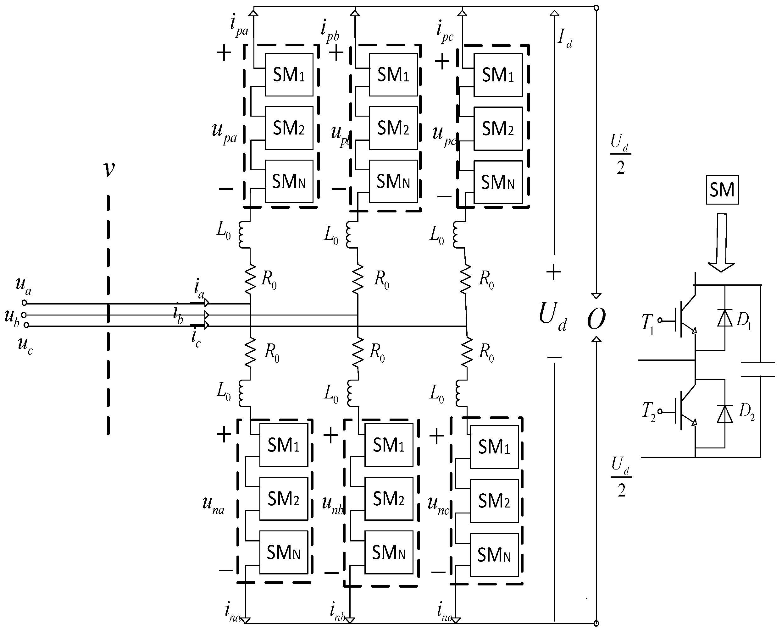
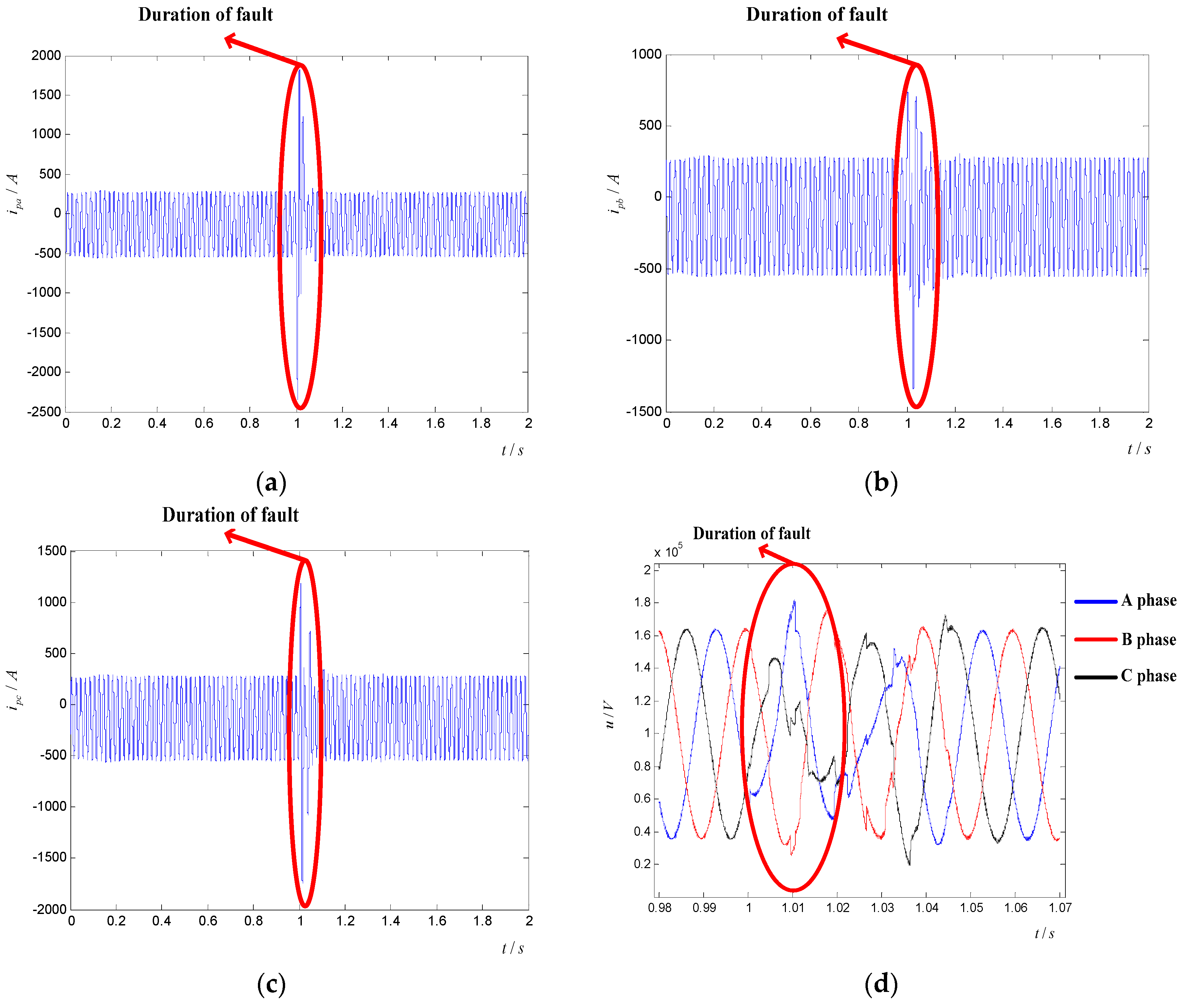
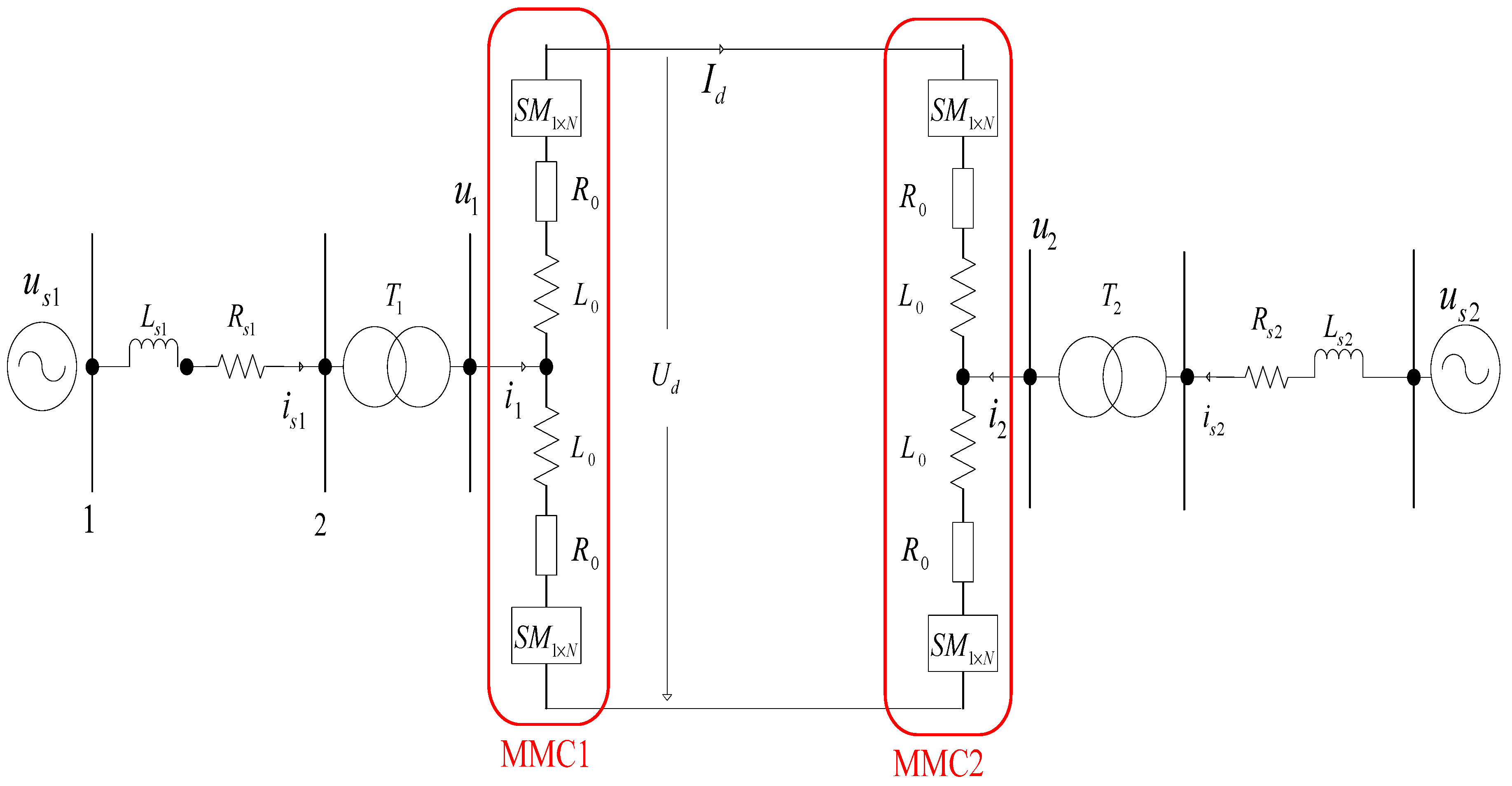
2. Influence of AC Transient Faults on MMC
3. Time Frequency Analysis of Arm Current under Transient Fault Condition
4. Feature Extraction of AC Transient Faults Based on Renyi Wavelet Packet Entropy
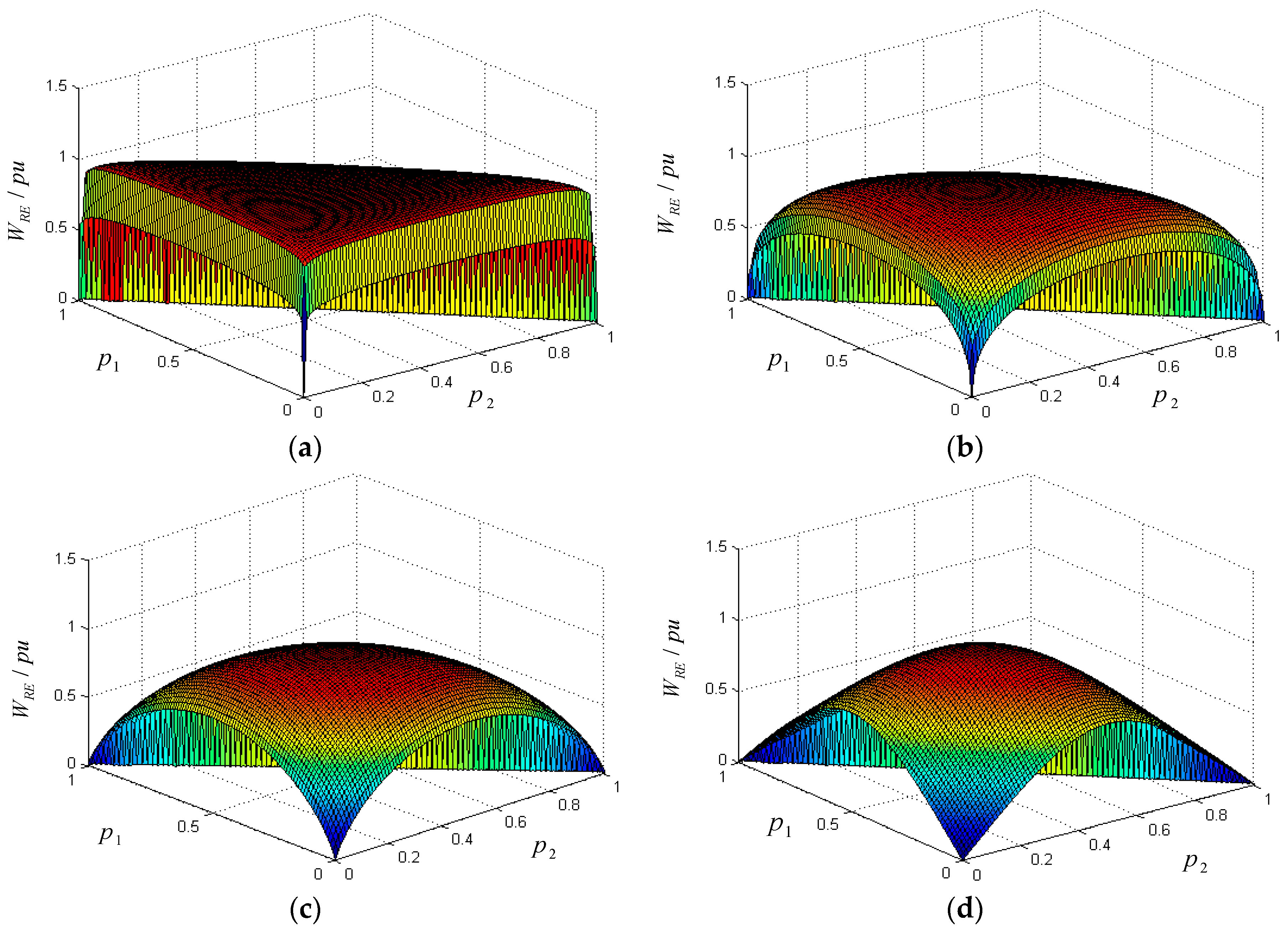
4.1. The Definition of Renyi Entropy
4.2. The Statistical Properties of Renyi Entropy
4.3. Renyi Wavelet Packet Energy Entropy
4.4. Renyi Wavelet Packet Time Entropy
4.5. ContrastAnalysisof RWPE and SWPE
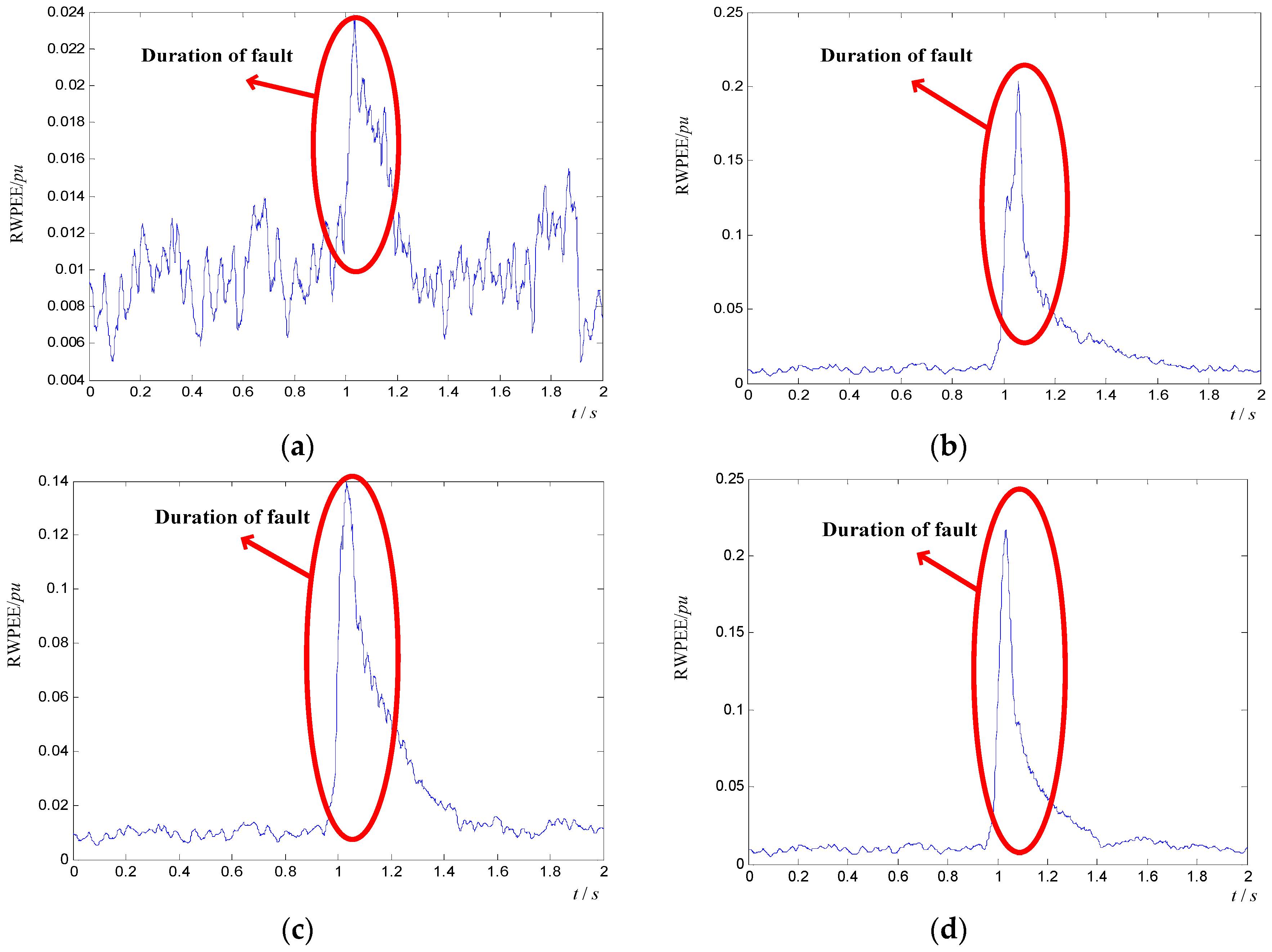
4.6. Feature Extraction of Transient Faults with RWPEE
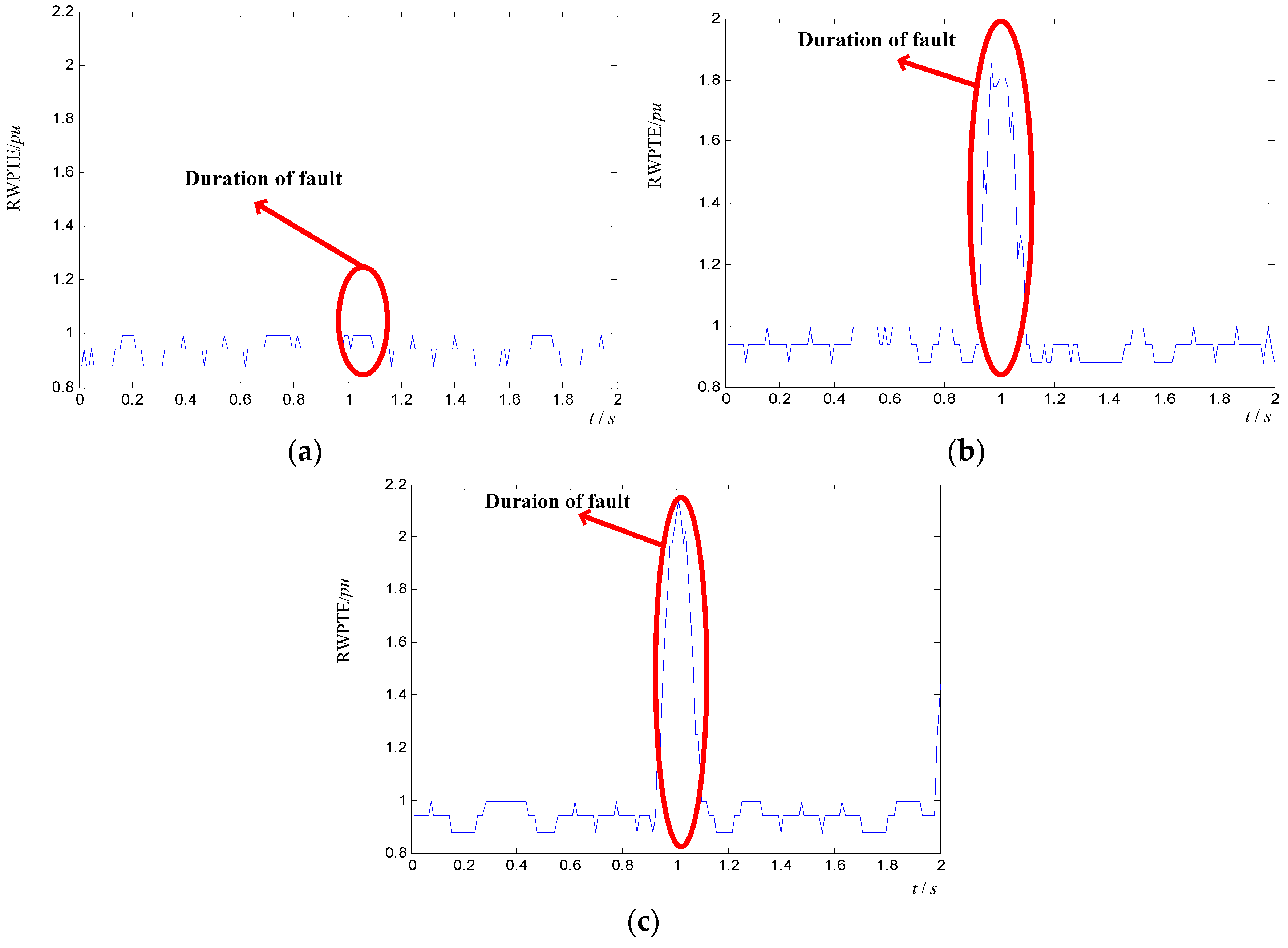
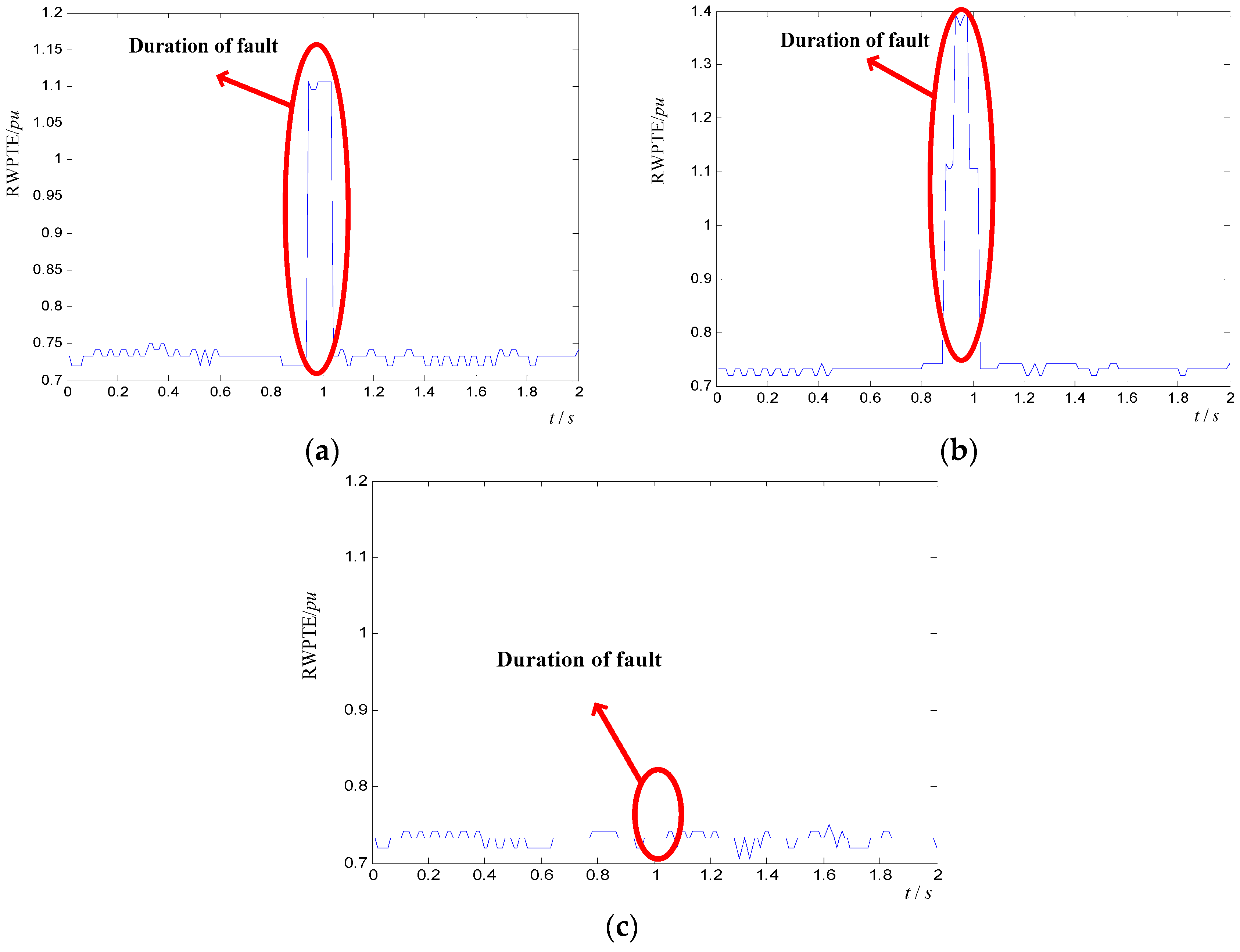
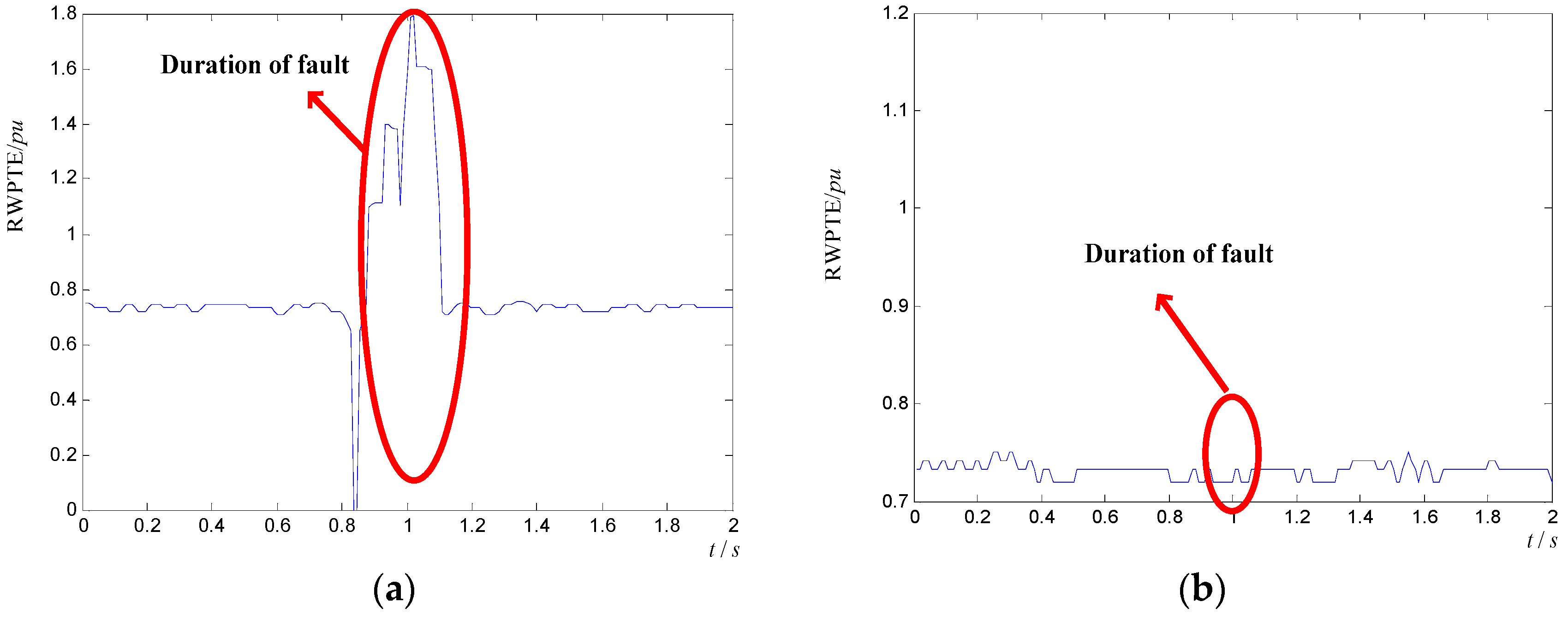
4.7. Feature Extraction of Transient Faults with RWPTE
5. Recognition of AC Transient Fault
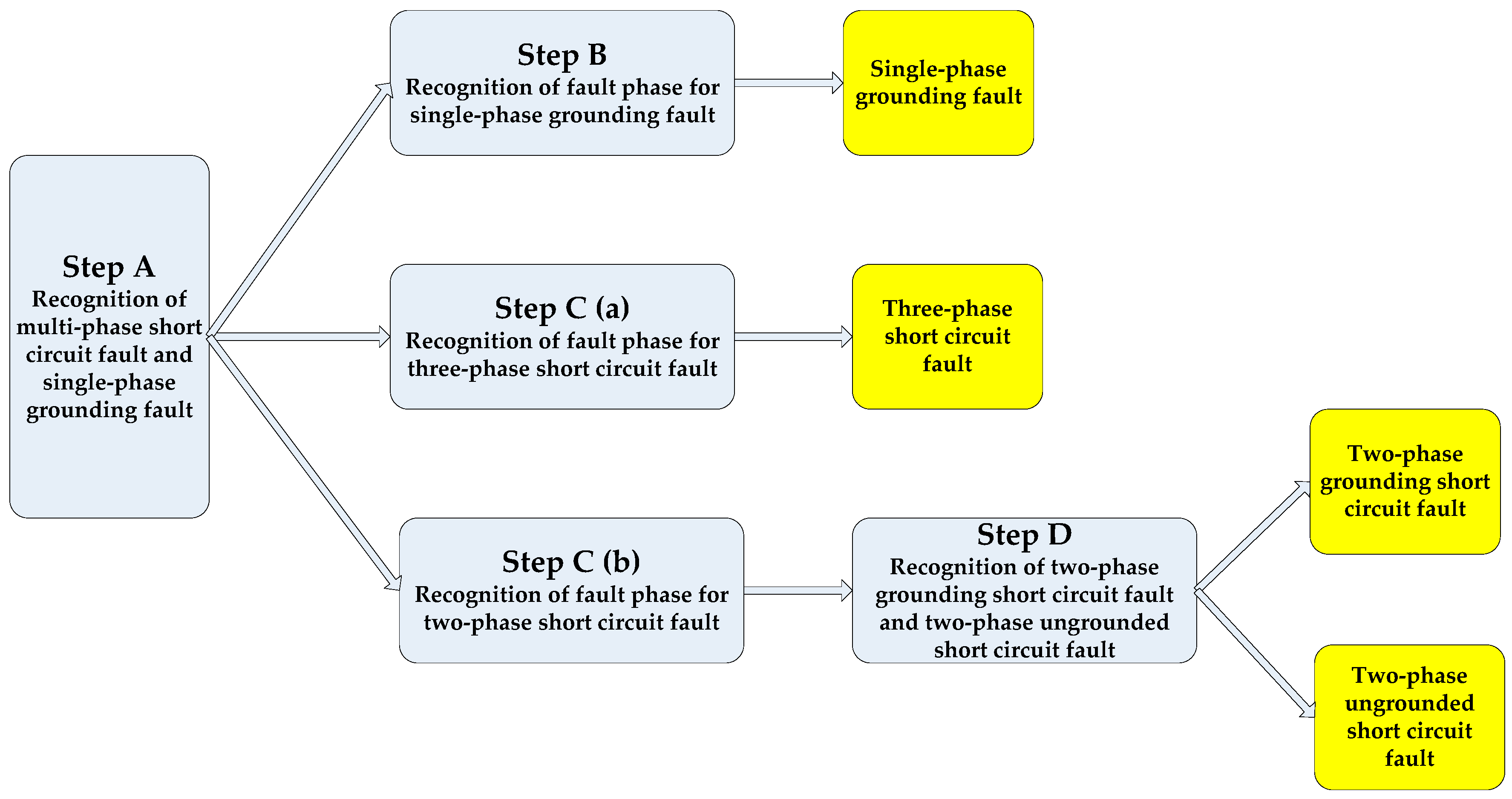
- A.
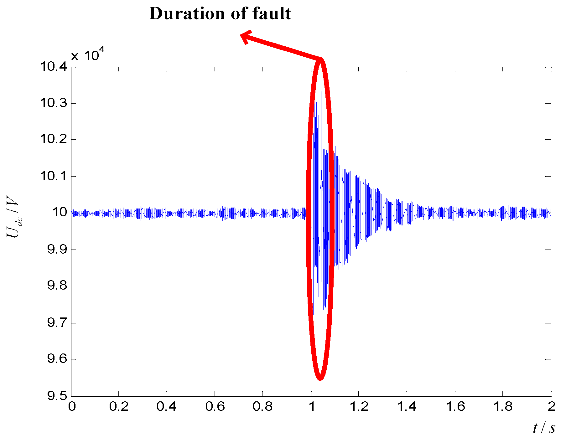
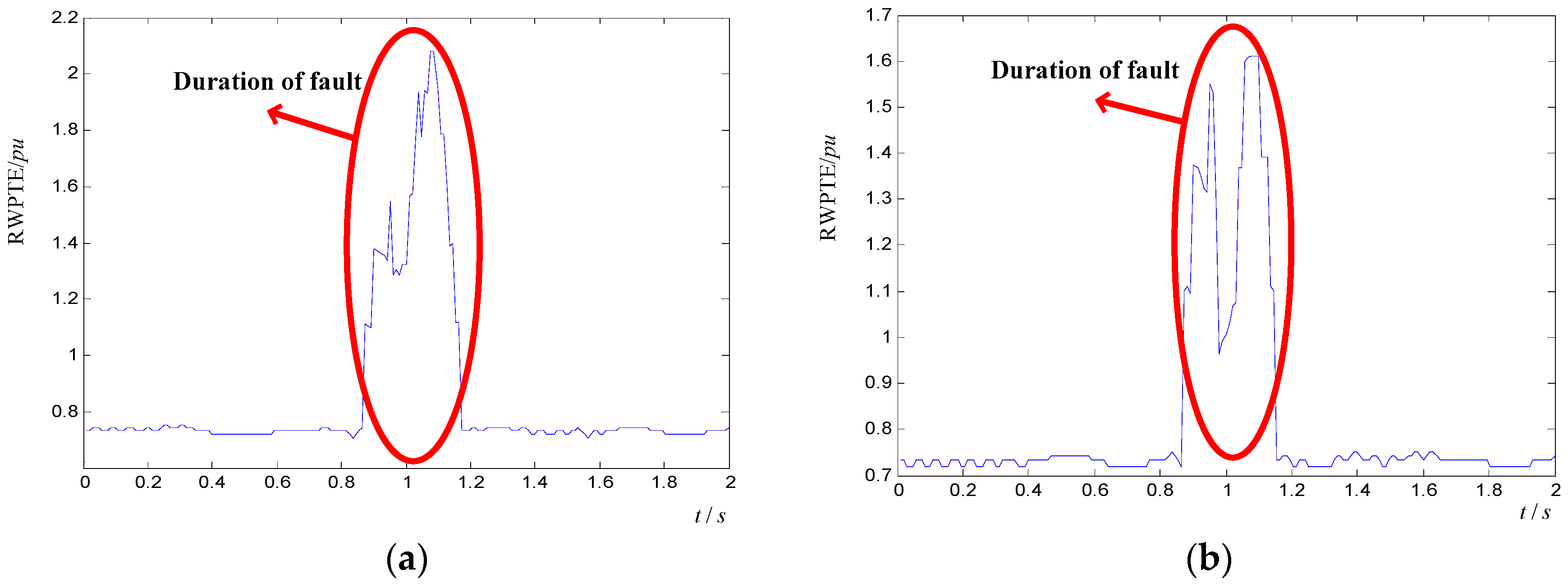
- DC bus voltage is sampled with 800 Hz, and RWPEE is performed on it. Comparing the maximum and average value of RWPEE, if the ratio is between 4 and 25, which implies that multi-phase fault occurs on AC transmission line. Otherwise, the single-phase grounding fault occurs. When the single-phase grounding fault occurs, fault phase can be judged by step B. Otherwise, step C can be used to judge multi-phase fault type and fault phase.
- B.
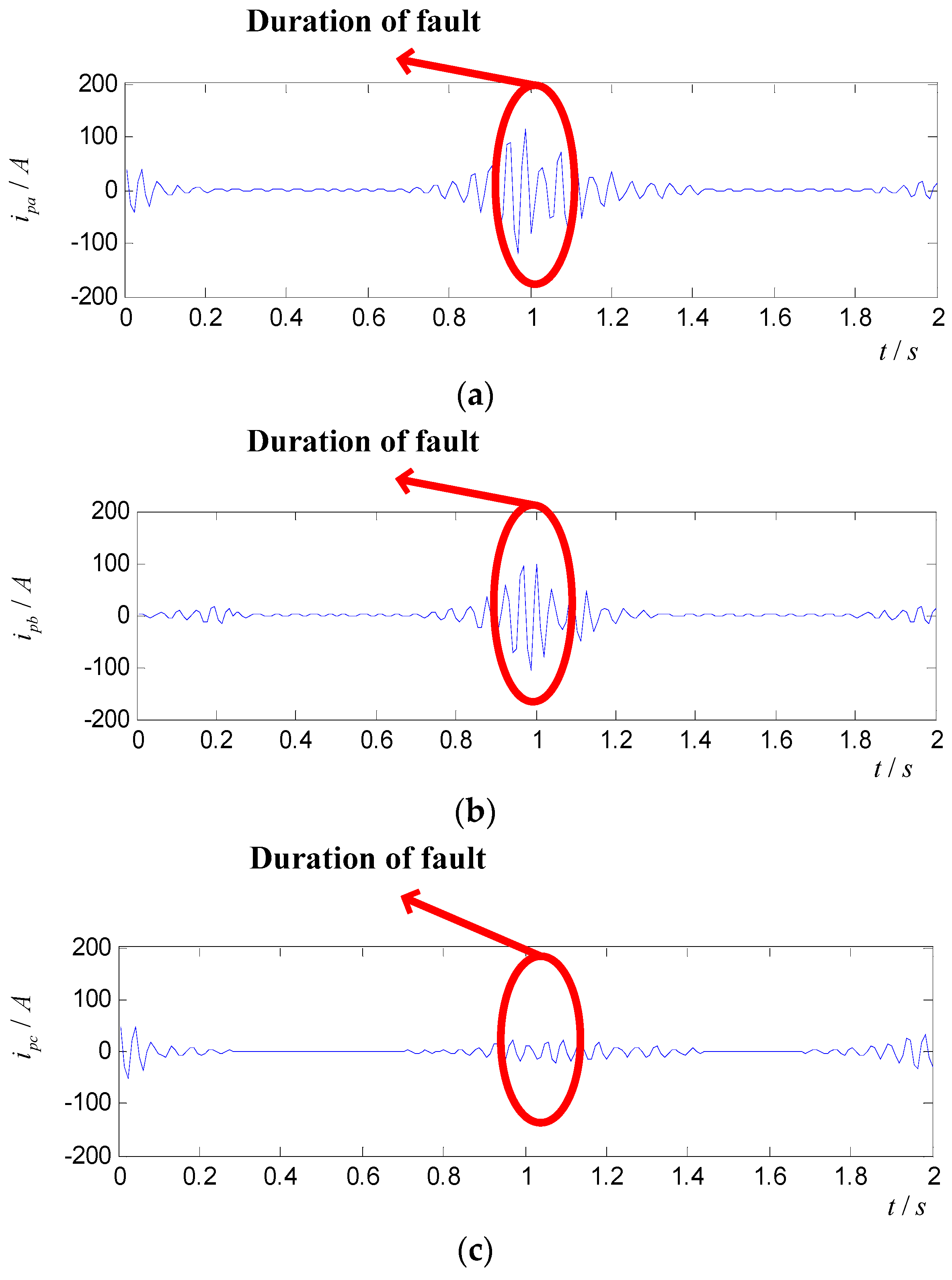
- Currents from the upper arm of three phases are respectively sampled with 112 Hz and RWPTE are computed for reconstruction signal in 42–29 Hz. The phase with entropy saltation is non-fault phase, and the phase without entropy saltation is fault phase. According to it, the fault phase of single-phase grounding fault can be confirmed.
- C.
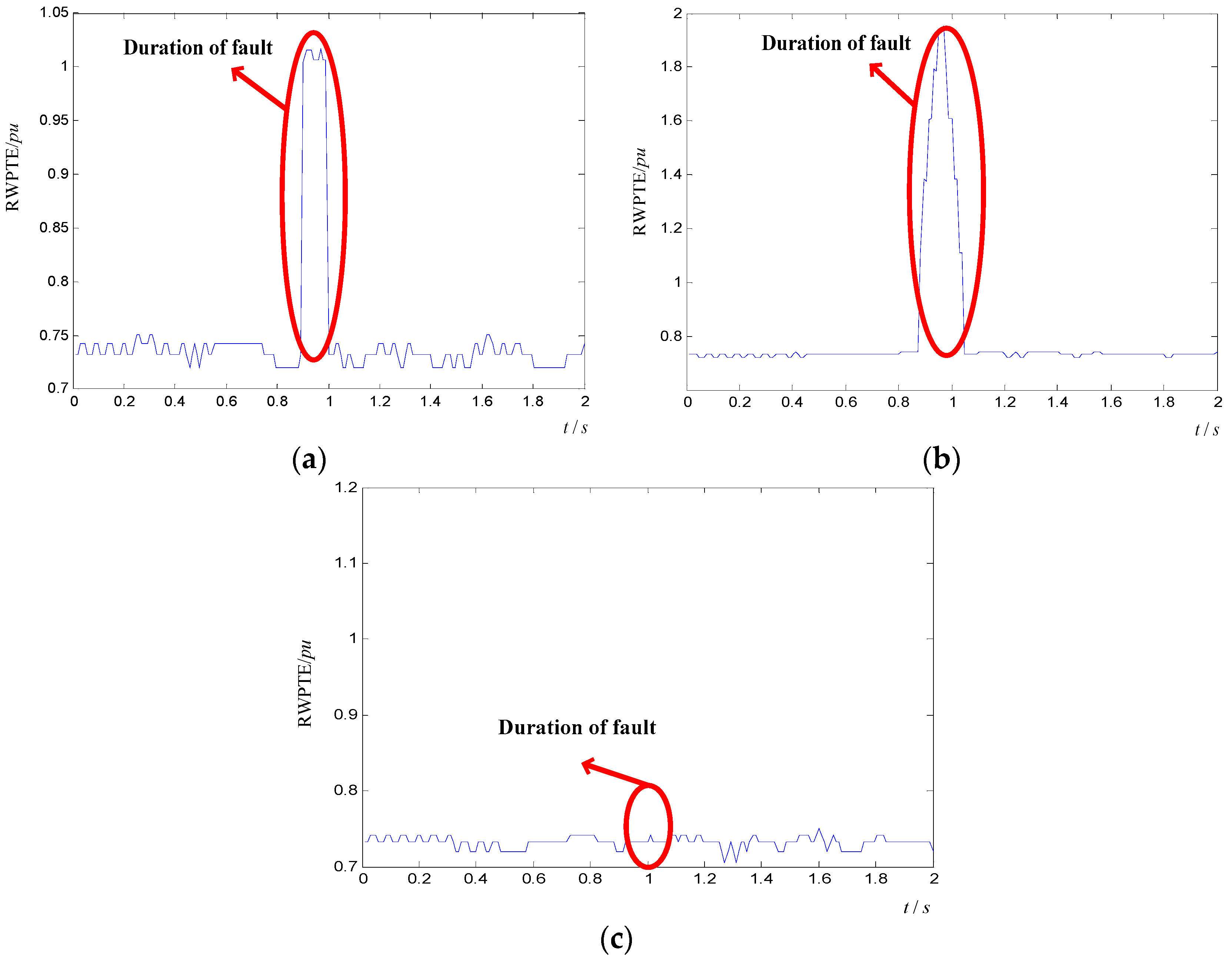
- Currents from the upper arm of three phases are respectively sampled with 112 Hz and RWPTE are computed for reconstruction signal in 14–28 Hz.
- a.
- Entropy saltation in three phases implies that three-phase short circuit fault occurs on AC transmission line and the fault phases are ABC phases.
- b.
- There is two-phase short circuit fault on AC transmission line, when the entropy saltation occurs in only two phases. Although only the two phases with entropy saltation can be determined as fault phase, the other fault phases have to be found based on step D.
- D.
- Fault phases can be identified according to step C. On this basis, RWPTE are computed for reconstruction signal in 7–14 Hz. If there is entropy saltation at the fault phase, it can be determined as two-phase grounding short circuit fault on AC transmission line. Otherwise, it is two-phase ungrounded short circuit fault.
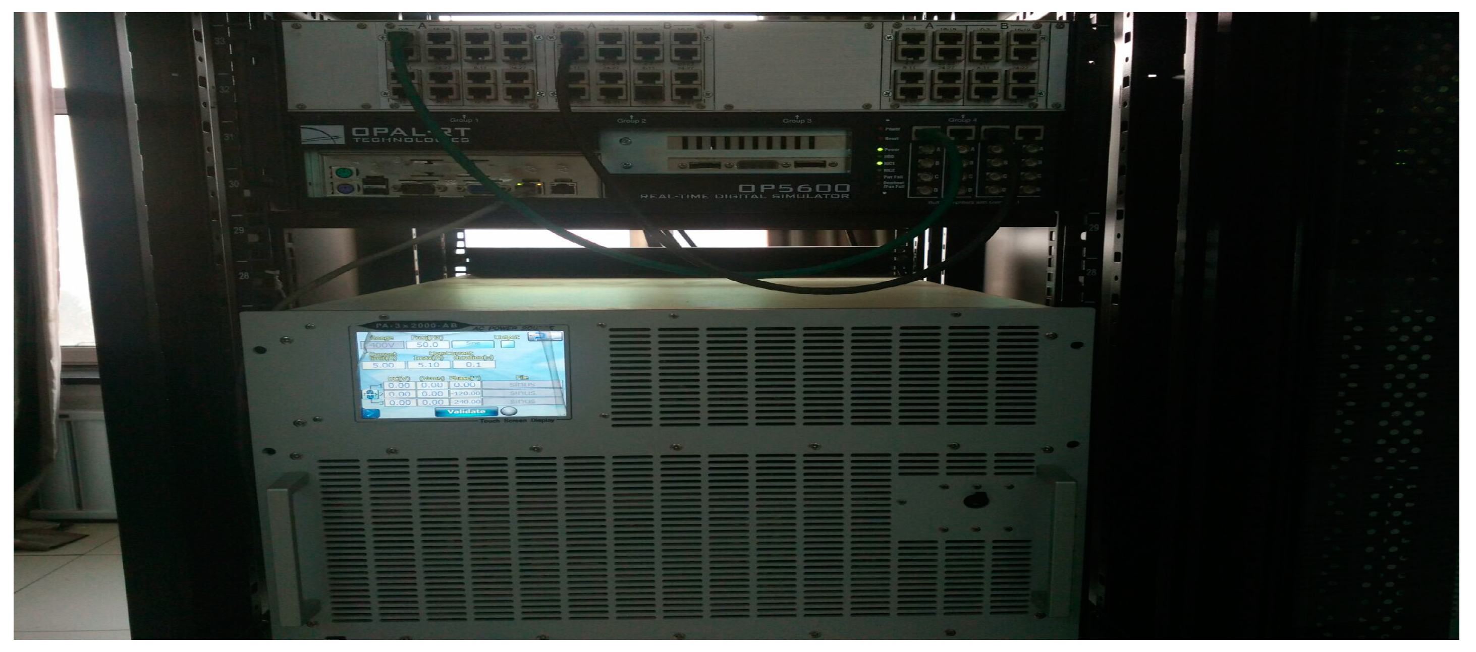
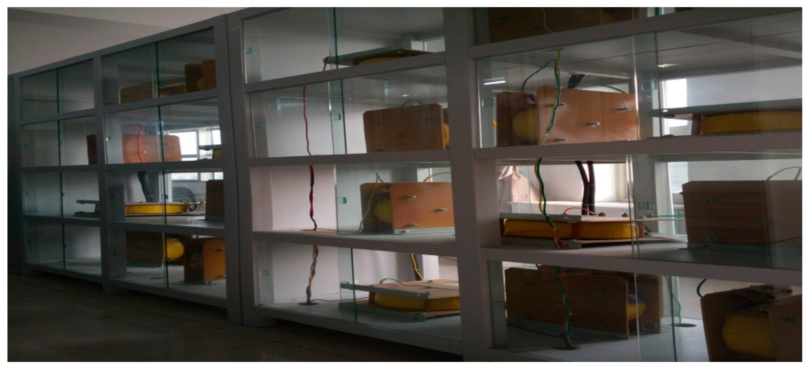
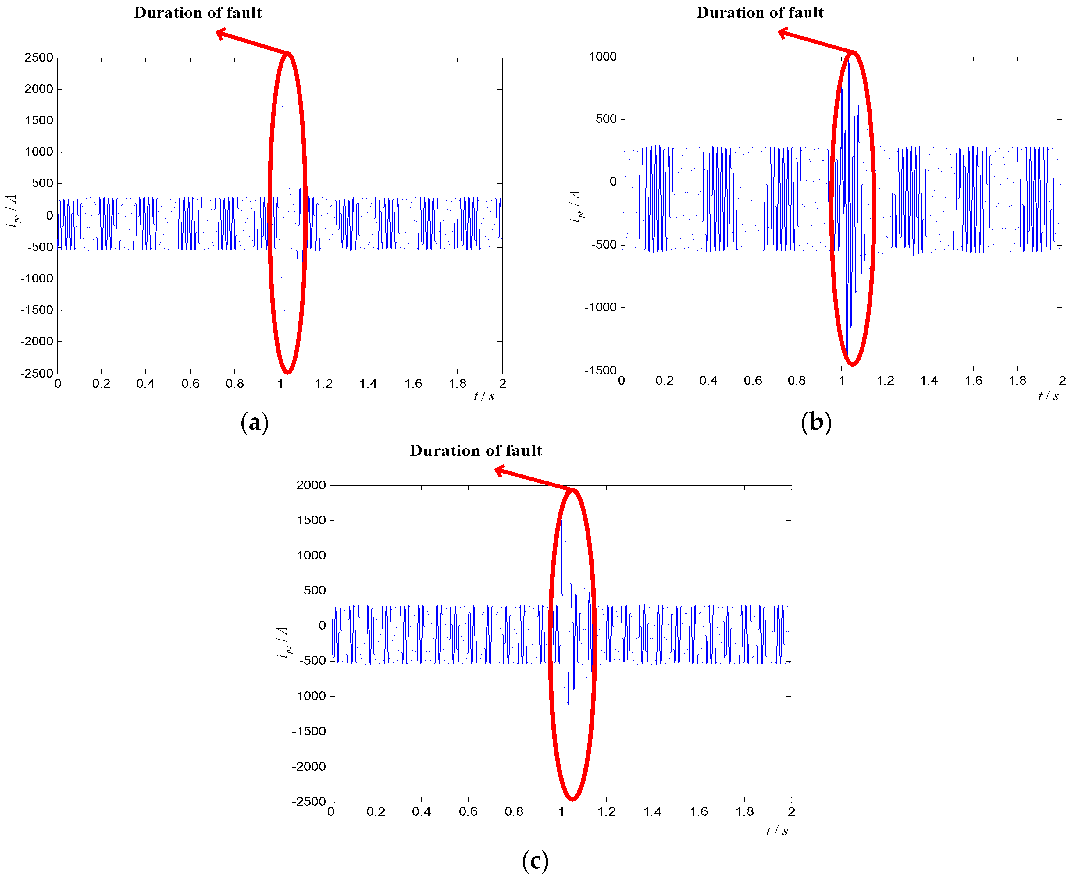
6. Stimulation
7. Conclusions
- (a)
- Different AC transient faults have different influence on MMC. It is difficult to recognize AC transient faults by using time-domain signals of electrical information in MMC.
- (b)
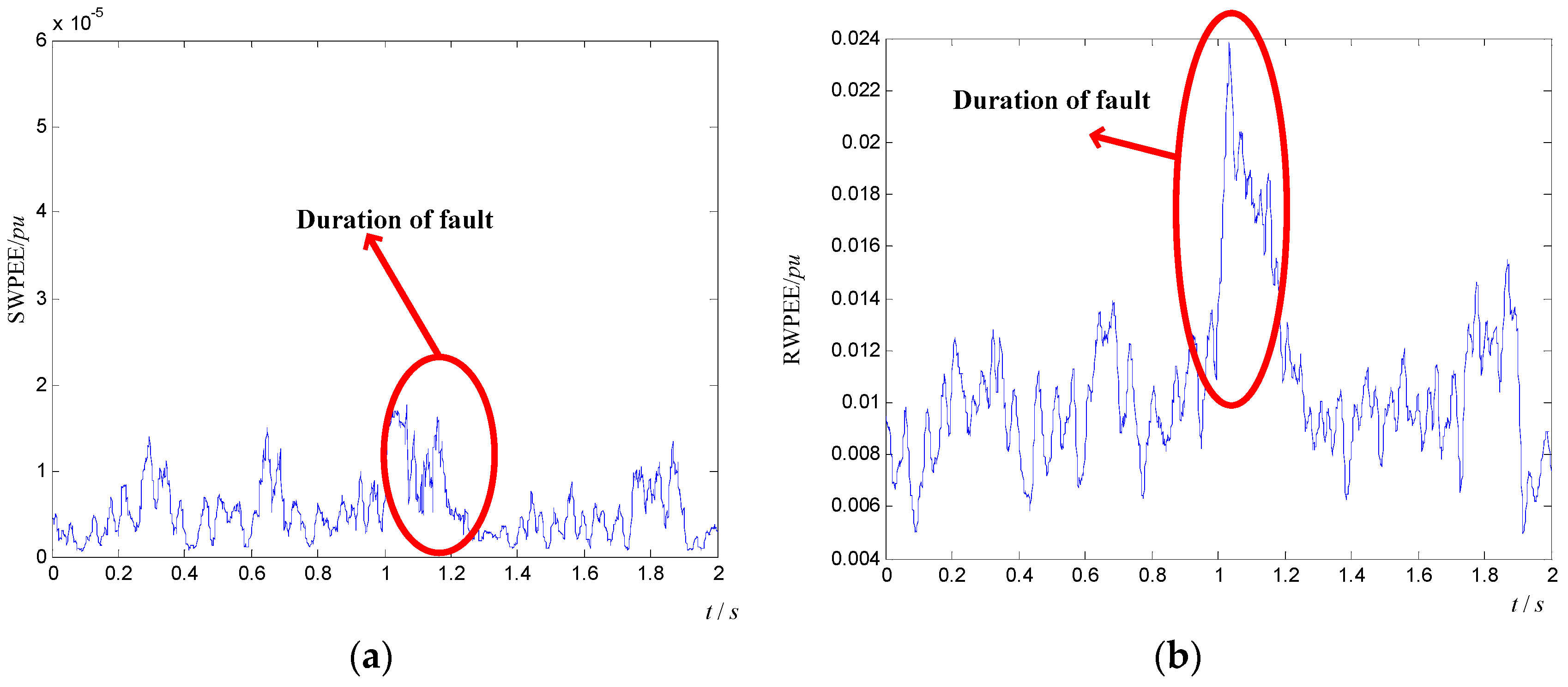
- Based on high resolution of DWPT in frequency-domain, the energy distribution of electrical signals in MMC are different for different arms in the same frequency bands after DWPT. According to the feature of energy distribution in the same frequency bands, RWPEE and RWPTE are proposed to extract feature of transient faults. In term of feature extraction accuracy and computation complexity, the methods proposed are better than SWPEE and SWPTE.
- (c)
- The recognition method proposed can simplify numerous and complicated electrical information and it achieves the recognition of AC transient faults in MMC-HVDC system. Compared with BP neural network recognition, the recognition method proposed is more accurate.
- (d)
- The conclusion provides theoretical support for the further analysis of operation state and AC-DC interaction for MMC-HVDC system. The next research will focus on how to reduce negative effects of transient faults on MMC from the results of this article, and the control strategy and evaluation of operation state will be proposed to optimize the performance of MMC-HVDC system.
Acknowledgments
Author Contributions
Conflicts of Interest
References
- Liu, H.; Ma, K.; Loh, P.C.; Blaabjerg, F. Online Fault Identification Based on an Adaptive Observer for Modular Multilevel Converters Applied to Wind Power Generation Systems. Energies 2015, 8, 7140–7160. [Google Scholar] [CrossRef]
- Saad, H.; Mahseredjian, J.; Dennetiere, S.; Nguefeu, S. Interactions studies of HVDC-MMC link embedded in an AC grid. Electr. Power Syst. Res. 2016, 138, 202–209. [Google Scholar] [CrossRef]
- Tu, Q.; Xu, Z. Impact of Sampling Frequency on Harmonic Distortion for Modular Multilevel Converter. IEEE Trans. Power Del. 2011, 26, 298–306. [Google Scholar] [CrossRef]
- Yu, F.; Wang, X.; Zhang, Y.; Wang, Z. Direct Circulating Current Suppressing Strategy for MMC under Unbalanced AC Grid Conditions. Power Syst. Technol. 2015, 39, 3339–3345. [Google Scholar]
- Hu, P.; Jiang, D.; Zhou, Y.; Liang, Y.; Guo, J.; Lin, Z. Energy-balancing control strategy for modular multilevel converters under sub-module fault conditions. IEEE Trans. Power Electron. 2014, 29, 5021–5030. [Google Scholar] [CrossRef]
- Tang, G.; Xu, Z.; Zhou, Y. Control and modulation strategies for modular multilevel converter based HDVC system. Power Syst. 2014, 29, 3030–3040. [Google Scholar] [CrossRef]
- Zhang, J.; Zhao, C. Control Strategy of MMC-HVDC under Unbalanced Grid Voltage Conditions. J. Power Electron. 2015, 15, 1499–1507. [Google Scholar] [CrossRef]
- Liu, Y.; Chen, Q.; Li, N.; Xie, B.; Wang, J.; Ji, Y. On DC-Side Impedance Frequency Characteristics Analysis and DC Voltage Ripple Prediction under Unbalanced Conditions for MMC-HVDC System Based on Maximum Modulation Index. J. Power Electron. 2016, 16, 319–328. [Google Scholar] [CrossRef]
- Ludois, D.; Venkataramanan, G. An Examination of AC/HVDC Power Circuits for Interconnecting Bulk Wind Generation with the Electric Grid. Energies 2010, 3, 1263–1289. [Google Scholar] [CrossRef]
- Xu, C.; Dai, K.; Chen, X.; Kang, Y. Voltage droopcontrolat point of common coupling with arm current and capacitor voltage analysis for distribution static synchronous compensator based on modular multilevel converter. IET Power Electron. 2016, 9, 1643–1653. [Google Scholar] [CrossRef]
- Guan, M.; Xu, Z.; Tu, Q.; Pan, W. Nearest Level Modulation for Modular Multilevel Converters in HVDC Transmission. Autom. Electr. Power Syst. 2010, 34, 48–52. [Google Scholar]
- Shao, S.; Wheeler, P.W.; Clare, J.C.; Watson, A.J. Fault detection for modular multilevel converters based on sliding mode observer. IEEE Trans. Power Electron. 2013, 28, 4867–4872. [Google Scholar] [CrossRef]
- Ma, Y.; Wang, W.; Zhang, J.; Tang, J.; Ren, T. Analysis of MMC-HVDC Transient Response Characteristic under Typical Disturbances. Proc. CSU-EPSA 2011, 23, 110–118. [Google Scholar]
- Qiu, P.; Zhang, S.; Huang, X.; Lu, Y.; Lu, M. Research on the protection strategies of internal AC bus fault based on MMC-HVDC. Power Syst. Prot. Control 2014, 42, 150–154. [Google Scholar]
- Ma, S.; Yu, L.; Zheng, L. Characteristics Analysis of MMC-HVDC AC Asymmetric Fault and Protection Strategy. J. North China Electr. Power Univ. 2015, 42, 35–43. [Google Scholar]
- Xiao, L.; Xu, Z.; Liu, S.; An, T.; Kong, M. AC Fault Ride through Strategy of MMC-HVDC Connected to Passive Networks. Trans. China Electrotech. Soc. 2016, 31, 120–128. [Google Scholar]
- Liang, Y.; Zhang, T.; Liu, J.; Yang, Q.; Liu, S. A Circulating Current Suppressing Method for Modular Multilevel Converter under Unbalanced Grid Voltage. Trans. China Electrotech. Soc. 2016, 31, 120–128. [Google Scholar]
- Yuan, X.; Gao, L.; Wen, J.; Cheng, S. Unbalanced three-phase control strategy of VSC-HVDC system. Electr. Power Autom. Equip. 2010, 30, 1–5. [Google Scholar]
- Li, X.; Liu, W.; Song, Q.; Rao, H.; Zhu, Z.; Li, X. An Enhanced MMC Topology with DC Fault Clearance Capability. Proc. CSEE 2011, 34, 6389–6397. [Google Scholar]
- Li, X.; Song, Q.; Liu, W.; Li, Q.; Rao, H.; Xu, S. Zero-sequence voltage injection control scheme of modular multilevel converter supplying passive networks under unbalanced load conditions. Electr. Power Syst. Res. 2015, 121, 270–278. [Google Scholar] [CrossRef]
- Guan, M.; Xu, Z. Modeling and control of a modular multilevel converter-based HVDC system under unbalanced grid conditions. IEEE Trans. Power Electron. 2012, 27, 4858–4867. [Google Scholar] [CrossRef]
- Guan, M.; Xu, Z.; Pan, W.; Zhang, J.; Zheng, X. Analysis and Control of Modular Multilevel Converter Based HVDC Transmission Systems during Grid Faults. High Volt. Eng. 2013, 39, 1238–1245. [Google Scholar]
- Liu, Z.; Cui, Y.; Li, W. Combined Power Quality Disturbances Recognition Using Wavelet Packet Entropies and S-Transform. Entropy 2015, 17, 5811–5828. [Google Scholar] [CrossRef]
- Chen, J.; Zhou, Z.; Li, H.; Xu, B. Study of Fast Wavelet Entropy’s Application in Feature Extraction of Transient Signals in Transmission Line. Trans. China Electrotech. Soc. 2012, 27, 219–225. [Google Scholar]
- Andreopoulos, Y.; Schaar, M.V.D. Generalized Phase Shifting for M-Band Discrete Wavelet Packet Transforms. IEEE Trans. Signal Proc. 2007, 52, 742–747. [Google Scholar] [CrossRef]
- Erdogmus, D.; Hild, K.E.; Principe, J.C.; Lazaro, M.; Santamaria, I. Adaptive blind deconvolution of linear channels using Renyi’s entropy with Parzen window estimation. IEEE Trans. Signal Proc. 2014, 52, 1489–1498. [Google Scholar] [CrossRef]
- Chen, J.; Dou, Y.; Wang, Z.; Li, G. A Novel Method for PD Feature Extraction of Power Cable with Renyi Entropy. Entropy 2015, 17, 7698–7712. [Google Scholar] [CrossRef]
- Chen, J.; Li, H.Y.; Yang, S.; Kou, B. Application of Wavelet Packet Singularity Entropy and PSD in Power Harmonics Detection. Trans. China Electrotech. Soc. 2010, 25, 193–199. [Google Scholar]
- Sun, L.; Hu, X.; Ji, Y. Fault Diagnosis for High Voltage Circuit Breakers with Improved Characteristic Entropy of Wavelet Packet. Proc. CSEE 2007, 27, 103–108. [Google Scholar]
- Chen, J.; Li, G. Tsallis Wavelet Entropy and Its Application in Power Signal Analysis. Entropy 2014, 16, 3009–3025. [Google Scholar] [CrossRef]


| Entropy | Complexity of RWPE Algorithm | Complexity of SWPE Algorithm | Computational Cost Savings |
|---|---|---|---|
| Time Entropy | |||
| Energy Entropy |
| Parameters | Value |
|---|---|
| Short circuit ratio | 10 |
| AC system voltage , | 230 kV |
| AC system equivalent inductance , | 0.2183 mH/km |
| AC system equivalent resistance , | 0.0001143 /km |
| Transformer turns ratio | 230 kV/64 kV |
| Transformer capacity , | 230 MVA |
| Connection mode , | |
| Arm equivalent inductance | 24 mH |
| Arm equivalent resistance | 0.4 |
| Number of SM | 100 |
| Fault Types and Fault Phase | Correct Recognition | The fault Phase is Misjudgment | The Fault Type is Misjudgment |
|---|---|---|---|
| A-phase groundingfault | 17 | 1 | 0 |
| B-phase groundingfault | 17 | 1 | 0 |
| C-phase groundingfault | 17 | 1 | 0 |
| AB-phase grounding short circuit fault | 17 | 1 | 0 |
| BC-phase grounding short circuit fault | 16 | 1 | 1 |
| AC-phase grounding short circuit fault | 17 | 0 | 1 |
| AB-phase ungrounded short circuit fault | 17 | 1 | 0 |
| BC-phase ungrounded short circuit fault | 16 | 1 | 1 |
| AC-phase ungrounded short circuit fault | 17 | 1 | 0 |
| ABC-phase short circuit fault | 18 | 0 | 0 |
| Fault Types and Fault Phase | Correct Recognition | The Fault Phase is Misjudgment | The Fault Type is Misjudgment |
|---|---|---|---|
| A-phase grounding fault | 16 | 1 | 1 |
| B-phase grounding fault | 17 | 1 | 0 |
| C-phase grounding fault | 16 | 2 | 0 |
| AB-phase grounding short circuit fault | 16 | 1 | 1 |
| BC-phase grounding short circuit fault | 15 | 2 | 1 |
| AC-phase grounding short circuit fault | 16 | 1 | 1 |
| AB-phase ungrounded short circuit fault | 16 | 1 | 1 |
| BC-phase ungrounded short circuit fault | 16 | 2 | 0 |
| AC-phase ungrounded short circuit fault | 17 | 1 | 0 |
| ABC-phase short circuit fault | 18 | 0 | 0 |
© 2016 by the authors; licensee MDPI, Basel, Switzerland. This article is an open access article distributed under the terms and conditions of the Creative Commons Attribution (CC-BY) license (http://creativecommons.org/licenses/by/4.0/).
Share and Cite
Chen, J.; Dou, Y.; Li, Y.; Li, J.; Li, G. A Transient Fault Recognition Method for an AC-DC Hybrid Transmission System Based on MMC Information Fusion. Energies 2017, 10, 23. https://doi.org/10.3390/en10010023
Chen J, Dou Y, Li Y, Li J, Li G. A Transient Fault Recognition Method for an AC-DC Hybrid Transmission System Based on MMC Information Fusion. Energies. 2017; 10(1):23. https://doi.org/10.3390/en10010023
Chicago/Turabian StyleChen, Jikai, Yanhui Dou, Yang Li, Jiang Li, and Guoqing Li. 2017. "A Transient Fault Recognition Method for an AC-DC Hybrid Transmission System Based on MMC Information Fusion" Energies 10, no. 1: 23. https://doi.org/10.3390/en10010023
APA StyleChen, J., Dou, Y., Li, Y., Li, J., & Li, G. (2017). A Transient Fault Recognition Method for an AC-DC Hybrid Transmission System Based on MMC Information Fusion. Energies, 10(1), 23. https://doi.org/10.3390/en10010023