
Damping Force Modeling and Suppression of Self-Excited Vibration due to Magnetic Fluids Applied in the Torque Motor of a Hydraulic Servovalve


1
School of Mechatronics Engineering, Harbin Institute of Technology, Harbin 150001, China
2
College of Energy and Power Engineering, Lanzhou University of Technology, Lanzhou 730000, China
3
Department of Mechanical Engineering, Hosei University, Tokyo 102-8160, Japan
*
Author to whom correspondence should be addressed.
Energies 2017, 10(6), 749; https://doi.org/10.3390/en10060749
Submission received: 30 March 2017
/
Revised: 6 May 2017
/
Accepted: 22 May 2017
/
Published: 27 May 2017
(This article belongs to the Special Issue Energy Efficiency and Controllability of Fluid Power Systems)
Abstract
:As a key component of hydraulic control systems, hydraulic servovalves influence their performance significantly. Unpredictable self-excited noise inside hydraulic servovalves may cause instability and even failure. Being functional, with higher saturation magnetization and increased viscosity when exposed to a magnetic field, magnetic fluids (MFs) have been widely used in dampers, sealing, and biomedical treatment. In this paper, magnetic fluids are applied in the torque motor of a hydraulic servovalve to exert damping and resistance for vibration and noise suppression. Construction of the torque motor armature with magnetic fluids is introduced and the forces due to magnetic fluids on the torque motor armature are studied. Based on a bi-viscosity-constituted relationship, a mathematical model of the damping force from magnetic fluids is built when magnetic fluids are filled in the working gaps of the torque motor. Measurements of the properties of an Fe3O4 composite magnetic fluid are carried out to calculate the parameters of this mathematical model and to investigate the influence of magnetic fluids on the vibration characteristics of the armature assembly. The simulated and tested harmonic responses of the armature with and without magnetic fluids show the good suppression effects of magnetic fluids on the self-excited noise inside the servovalve.
1. Introduction
Magnetic fluids show a reversible transition from liquid to solid behavior, characterized by the apparent viscosity variation with several orders of magnitude under the action of an external magnetic field. Being a functional material with both magnetic properties of solid magnetic materials and fluidity of liquids, magnetic fluids have been widely used in a large variety of engineering and biomedical applications, such as vacuum sealing, bearings, lubrication, and insulation [1,2,3]. Marinica et al. [4] studied the static properties and magnetorheological behavior of a set of 12 nano-micro composite magnetic fluids for rotation seal and vibration damper applications. An Mn-Zn ferrite magnetic fluid (TCF-56) has been investigated as a coolant in a 3 kW prototype transformer for overloading conditions by Patel et al. [5]. A ninefold increase in normal life expectancy was shown by the application of TCF-56 compared to the use of pure oil. Li and Shinshi [6] made use of magnetic fluids as a lubricant to avoid the leakage of lubricating oil under a sliding planar motion table and reduced environmental pollution. A stroke larger than that of the hinge mechanism was realized with less complexity and relatively higher stiffness. Biomedical applications have also been developed to magnetically modify various types of organic or inorganic materials or microbial cells with magnetic fluids [7,8]. Due to the increased saturation magnetization of magnetic fluids exposed to a magnetic field, the application of magnetic fluids in vibration control and dampers especially have received a great deal of attention [9,10,11]. Magnetic fluids were filled in a U-tube to develop a tuned liquid column damper (TLCD) by Oyamada et al. [12]. Li and Song applied magnetic fluids in the torque motor of hydraulic servovalves to improve their stability [13].
However, to apply a functional fluid practically and properly, the properties of the materials are of significance and thus merit investigation and verification [14,15,16]. The dynamic properties of magnetic fluids were investigated with low-frequency, polarized, complex susceptibility measurements by Li et al. [17]. Manukyan et al. [18] compared the wetting characteristics of an oil-based ferrofluid and a water-based magnetic paint on a hydrophobic flat surface. For the application in vibration absorbers and dampers, it is essential to investigate the mechanical properties of magnetic fluids [19,20,21]. Hayashi et al. [22] studied the resistance force of a shock absorber due to magnetic functional fluids containing both micrometer-sized and nanometer-sized magnetic particles. Damping properties of magnetic fluids when applied in an electrohydraulic servovalve torque motor for vibration suppression were measured by Peng et al. [23]. Gstöttenbauer et al. introduced the three modes of operation for magnetic fluids. To numerically describe the squeeze mode, in which magnetic fluid is squeezed along the direction of the exerted magnetic field, adequate constitutive laws were applied, checked numerically by utilizing finite-element simulations, and validated against experimental data [24]. However, commercial applications of the squeeze mode are still restricted due to a lack of understanding and modeling of the material behavior, while further investigations still need to be carried out on the mathematical models of damping forces and resistance from magnetic fluids in the application of vibration absorbers and dampers. Therefore, the aim of the paper is to build a mathematical model of damping force from magnetic fluids for vibration suppression in a torque motor, and to study the mechanism of operation mechanism of magnetic fluids in the squeeze mode, via simulation and experiment of the harmonic response of the armature with magnetic fluids.
Hydraulic servovalves are the most important components of hydraulic control systems, which are very widely applied in the areas of industry, aerospace, agriculture, and automobiles. The characteristics of a hydraulic servovalve significantly influence the performance of a hydraulic control system [25]. Self-excited pressure oscillations and high-frequency noise appearing unpredictably in hydraulic servovalves will cause performance deterioration, or even failure, in the valves. In this paper, magnetic fluids are filled in a hydraulic servovalve to overcome the self-excited noise and to improve its performance. Mathematical models of damping due to magnetic fluids when they are exposed to the magnetic field inside the gaps of the torque motor are investigated. To calculate the necessary parameters of the mathematical models, identifications are carried out based on the measurements and experimental data concerning the properties of the magnetic fluids. The vibration characteristics of the armature with magnetic fluids are simulated, and the self-excited noise of the servovalve with magnetic fluids is tested.
2. Construction of a Torque Motor with Magnetic Fluids
A torque motor is one of the key mechanisms by which electrical signals are converted to mechanical movements of the armature in hydraulic servovalves. The construction of a torque motor in a hydraulic servovalve with magnetic fluids is shown in Figure 1. The dimensions of the torque motor are 38 mm × 28.5 mm × 22.25 mm. As the driving part of the servovalve, the torque motor moves the flapper or jet pipe linked to the armature in the pilot stage of the servovalve to a rotation angle after a current is supplied to the coil of the motor. It can be seen from Figure 1, when the current supplied to the coil is zero, the magnetic flux densities inside the four working gaps are almost the same. The output torque of the motor is nearly zero, and the armature will not rotate. If the current is not zero, the magnetic flux densities inside Gaps 1 and 3 on one diagonal become larger than those inside the other two gaps (2 and 4). There will then be an output torque of the motor, and the armature will rotate. If magnetic fluids are filled into the gaps between the torque motor armature and cores, a large saturation magnetization will be shown by the magnetic fluids exposed to the magnetic field of the torque motor. Thus, the influence of magnetic fluids can be exerted on the armature to suppress the unexpected self-oscillation of the armature with high frequency. Magnetic fluid will stay inside the gaps between armature and cores because of the permanent magnetic field that exists in the gaps, even when the power of the motor is turned off.
As shown in Figure 1, when the armature rotates, the working gaps of the torque motor will become smaller or larger. The function of magnetic fluids inside the gaps can be regarded as a spring with a tunable stiffness and a damper. As the movement of the end of the armature is required to be small by the stability criteria of the servovalve, it is usually less than one-third of the working gap (0.2 mm in this paper). Therefore, the movement of the end of the armature can be regarded as a displacement along the direction of the magnetic field exerted inside the working gap, although the armature actually rotates when the electric current is supplied to the torque motor. The operation mode of the magnetic fluids can be taken as a squeeze mode due to the displacement of the armature.
3. Mathematical Models of Magnetic Fluids
Magnetic fluids show a larger saturation magnetization and increased viscosity when exposed to a magnetic field. The magneto-viscosity of magnetic fluids is a property that is critical to the application of magnetic fluids in a servovalve for the suppression of self-excited noise. For different magnetic fields and different densities of magnetic fluid, the magneto-viscosity of a magnetic fluid will be different. Therefore, the magneto-viscosity characteristics of the magnetic fluid applied in this paper were measured and are shown in Table 1 under the saturated condition. Assuming that the flow of magnetic fluids inside the gaps is steady and uncompressible, for the squeeze working mode of magnetic fluids in Figure 1, a bi-viscosity model in Equation (1) can be used to describe the constitutive characteristics of the magnetic fluid [26]:
where represents the radial shear stress in the plane perpendicular to x axis (Pa); represents the radial velocity (m/s); represents the viscosity at the unyielding zone (Pa·s); represents the viscosity at the yielding zone (Pa·s); represents the yield stress (Pa); and represents the dynamic yield stress (Pa), .
For the squeeze flow, the radial velocity (ur) will decrease from the central plane to the upper and lower wall surfaces. Thus, the sign of will always be positive, when x < 0. The radial shear stress τxr will also be positive in the zone where x < 0. Therefore, for the zone where x < 0, |τxr| < τ1 can be written as 0 < τxr < τ1 and |τxr| ≥ τ1 can be written as τxr ≥ τ1. To simplify the analysis, only the zone where x < 0 in the considered gap is taken to be analyzed as the sign of will always be positive here to make the analysis easier. Therefore, Equation (1) can be simplified as:
If the armature stays at the neutral position, then h and L in Figure 1 are 0.375 mm and 2.5 mm, respectively. When the armature rotates, the maximum displacement and velocity of the armature end is 76.9 μm and 0.54 m/s, respectively. For the squeeze working mode in Figure 1, the displacement of the armature x is less than 40 μm, and the velocity of the armature V0 is 0.05–0.3 m/s. As the displacement of the armature is small enough, linear characteristics of the damping force on the armature due to the magnetic fluid working in the squeeze mode in the working gaps of the torque motor can be assumed and expressed simply as
where represents the equilibrium spring stiffness of magnetic fluid (N/m); represents the equilibrium damping coefficient (); x represents the displacement of the armature (μm); and represents the velocity of the armature end (m/s).
An Fe3O4 composite magnetic fluid produced by a local manufacturer (Heilongjiang Provincial Institute of Chemical Engineering, Harbin, China) was applied here. It is an ester-based magnetic fluid with 40% concentration of Fe3O4. Dioctyl sebacate was used as the carrier fluid of the magnetic fluid (MF) applied. The diameter of Fe3O4 magnetic nanoparticles in the magnetic fluids was 10 nm. The saturation magnetization of the magnetic fluid was tested to be 450 Gs, and the magnetic induction intensity of the magnetic field inside the working gaps changed from 2100 to 2500 Gs when we measured it with a gauss meter (TX-15, Ch-Hall Co., Ltd., Beijing, China). The magnetic induction intensity in the working gaps caused by the permanent magnetic field was measured to be around 2135 Gs. The magnetic-viscosity properties of the magnetic fluid were measured by a viscometer (RVDV-II+Pro, Brookfield Company, Middleboro, MA, USA). From the experimental data, the relationship between the dynamic yield stress and the magnetic induction intensity was obtained.
By curve fitting, as shown in Figure 2, when the end of the armature vibrates within a very small range around the neutral position, the parameters in the mathematical model of the damping force in Equation (3) can be calculated as = 218 N/m and = 0.34 N∙s/m for the magnetic fluids applied here, respectively. From the analysis and the mathematical model built above, if we want to take the influence of the magnetic fluids into account in the vibration analysis of the armature with FEM (finite element methods), we can regard the work of magnetic fluids as that of a spring and a damper in the torque motor. When the dynamic response of torque motor with magnetic fluids is considered, the model for magnetic fluids can also be built and combined with the dynamic model of torque motor with or without magnetic fluids [13].
4. Harmonic Response of an Armature with Magnetic Fluids
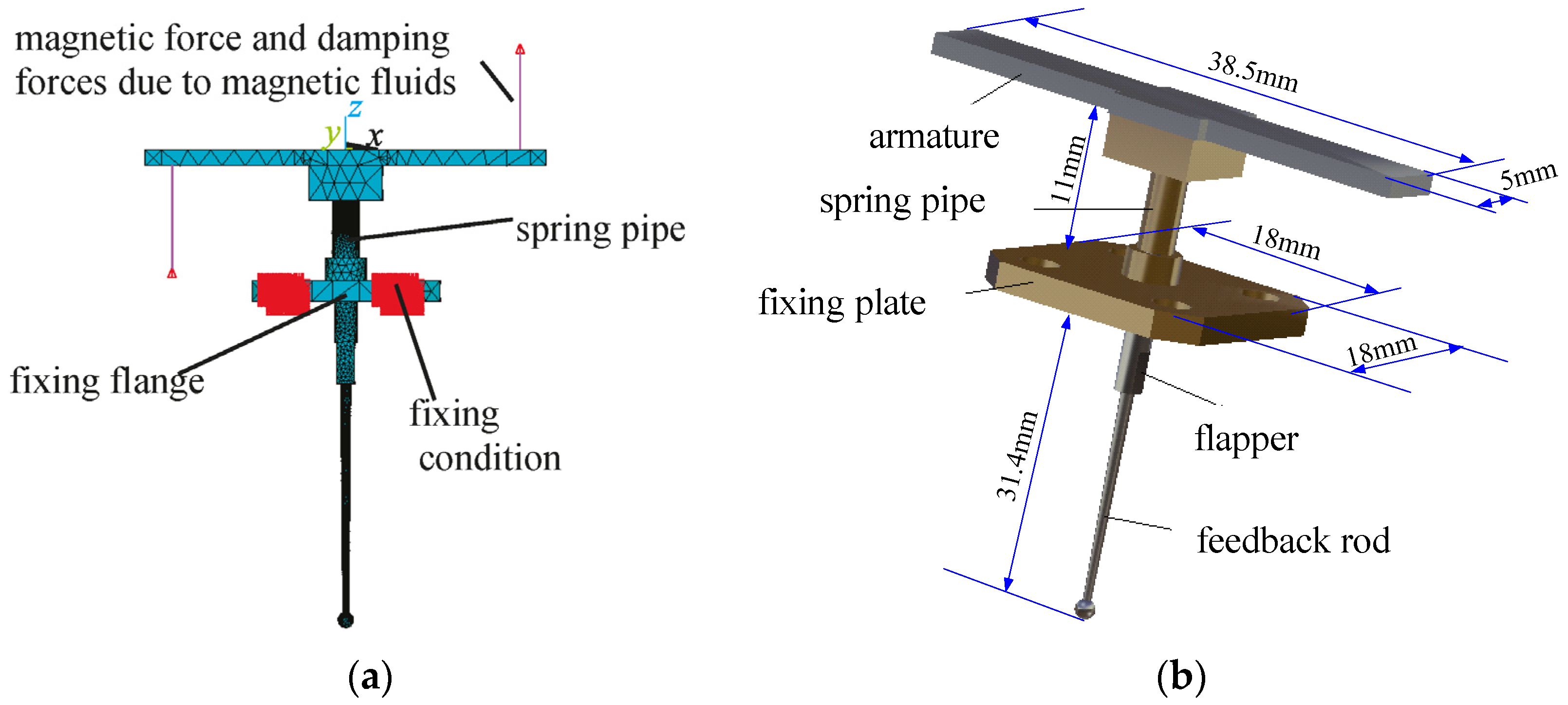
By applying the mathematical model in Equation (3) and the parameters calculated from the experimental data for the mathematical model, the damping force from magnetic fluids can be considered in the vibration mode and harmonic response analysis of the armature with FEM. The geometry model of the armature assembly with meshes and boundary conditions is shown in Figure 3a for the analysis of vibration modes. In the analysis, the armature is fixed at the flange of the spring pipe. Magnetic force due to the input electric current of the torque motor is exerted on the end of the armature. When the input electric current is 0.01 A, the magnetic force can be calculated as 0.086 N. Assuming that the damping ratio for the Rayleigh vibration model is constant for the frequency range of interests, it is taken as 0.03 in the analysis from experience.
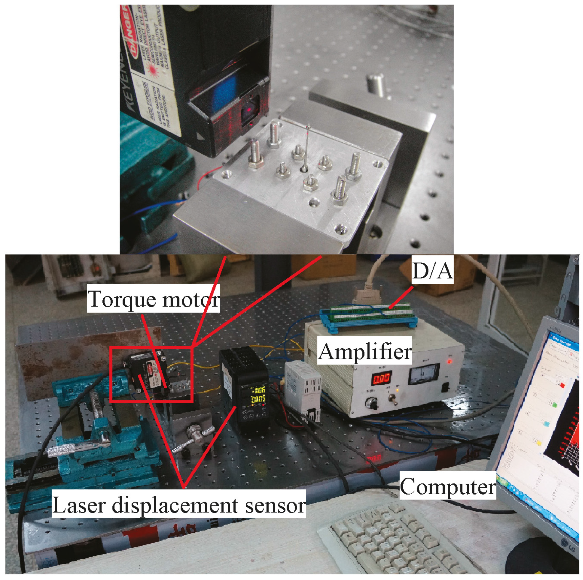
The tested sample of armature is shown in Figure 3b, and the experimental setup to test the vibration of the armature is shown in Figure 4. The torque motor from an electro-hydraulic servovalve (Chinese servovalve manufacturer, SL100, Beijing, China) was separately installed on a support from the main valve. Sinusoidal electric current signals were applied to exert the magnetic force on the armature with frequencies up to 4500 Hz. With the aid of a high-speed laser displacement sensor (LK-G5000, Keyence, Osaka, Japan), the harmonic responses in the x direction at the end of the feedback rod were measured both when magnetic fluids in the torque motor were applied and when they were not. The experimental data was transferred to a computer through the data acquisition system.
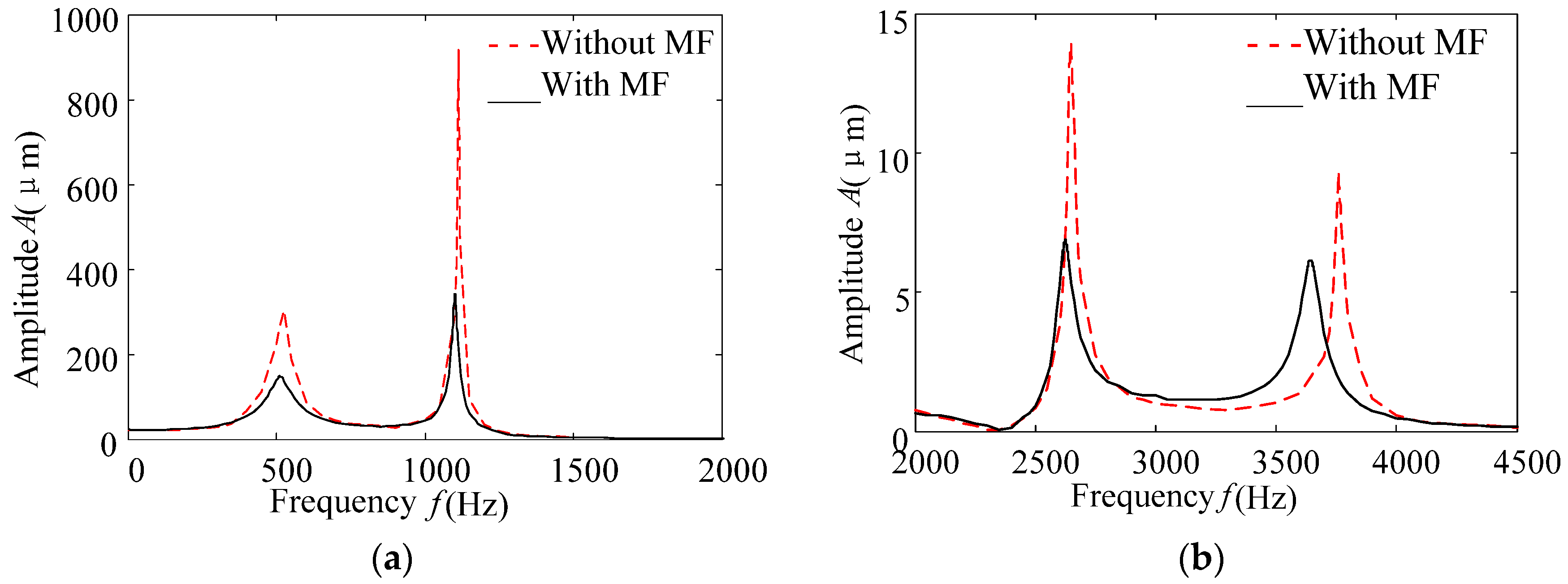
The simulated harmonic responses of the armature with or without magnetic fluids are shown in Figure 5a,b. From the predicted harmonic responses of the armature with or without magnetic fluids in Figure 5, it can be seen that there are four resonance peaks at the frequencies of 500 Hz, 1150 Hz, 2700 Hz, and 3800 Hz, respectively. When magnetic fluids are applied in the torque motor, the resonance peaks of the armature at the four frequencies are all reduced. The calculated resonance peak and damping ratio of the armature are given in Table 2. The resonance peak at 500 Hz in Figure 5a and that of the first-order vibration mode in Table 2 are depressed more significantly than those at the other frequencies by 60.8% when magnetic fluids are applied, while it seems that the resonance peak of the sixth-order vibration mode is reduced less obviously by 33% at 2700 Hz in Figure 5b and Table 2 than those at the other three frequencies if magnetic fluids are filled in the working gaps of the torque motor. Therefore, it can be concluded that magnetic fluids can depress the high frequency vibration of the armature by reducing the amplitude of resonance with the damping force exerted on the armature.
The tested harmonic responses of the armature with and without magnetic fluids are shown in Figure 6. It can be seen from Figure 6 that there are also four resonance peaks when the armature is tested with or without magnetic fluids, which illustrates a good agreement between the simulation results and the experimental data. However, when the magnetic fluid is applied in the torque motor, the four resonance frequencies are all tested to be smaller than those four frequencies when magnetic fluids are not applied. The four resonance frequencies are 510 Hz, 1210 Hz, 2700 Hz, and 3800 Hz when magnetic fluids are not applied. When the magnetic fluids are filled into the torque motor, the four resonance frequencies are 500 Hz, 1100 Hz, 2650 Hz, and 3650 Hz, respectively. This means that magnetic fluids will influence not only the damping ratio of the vibration mode but also the natural frequency. When magnetic fluids are applied in the torque motor, the attached mass of the magnetic fluid in the system will lead to the suppression in resonant frequency, but the deviation of the resonance frequency is somehow not obvious from Figure 6. It can also be helpful for applications where magnetic fluids are used for the suppression in resonant frequencies of the armature.
Because of the property when exposed to a magnetic field, MF behaves very differently from normal fluids by changing its viscosity and shear stress remarkably and reversibly due to magnetic fields. It can work in a squeeze mode by exerting damping force and resistance to the armature. Especially, the MF will always stay in the working gaps due to the electromagnetic force, even when it is compressed. However, for normal fluids without magnetorheological properties [24], the damping force is only due to the basic constant viscosity, because these normal fluids will easily flow away when the armature vibrates. Therefore, normal fluids can hardly work as a damper in the servovalve’s environment to suppress the vibration of the armature assembly. As the torque motor of a servovalve usually works in a dry mode, in the comparison plots (Figure 5 and Figure 6), “without the MF” means that no fluid is added in the working gaps of the torque motor. The damping on the armature in the simulation is only due to the air and mechanical damping.
5. Tested Self-Excited Noise
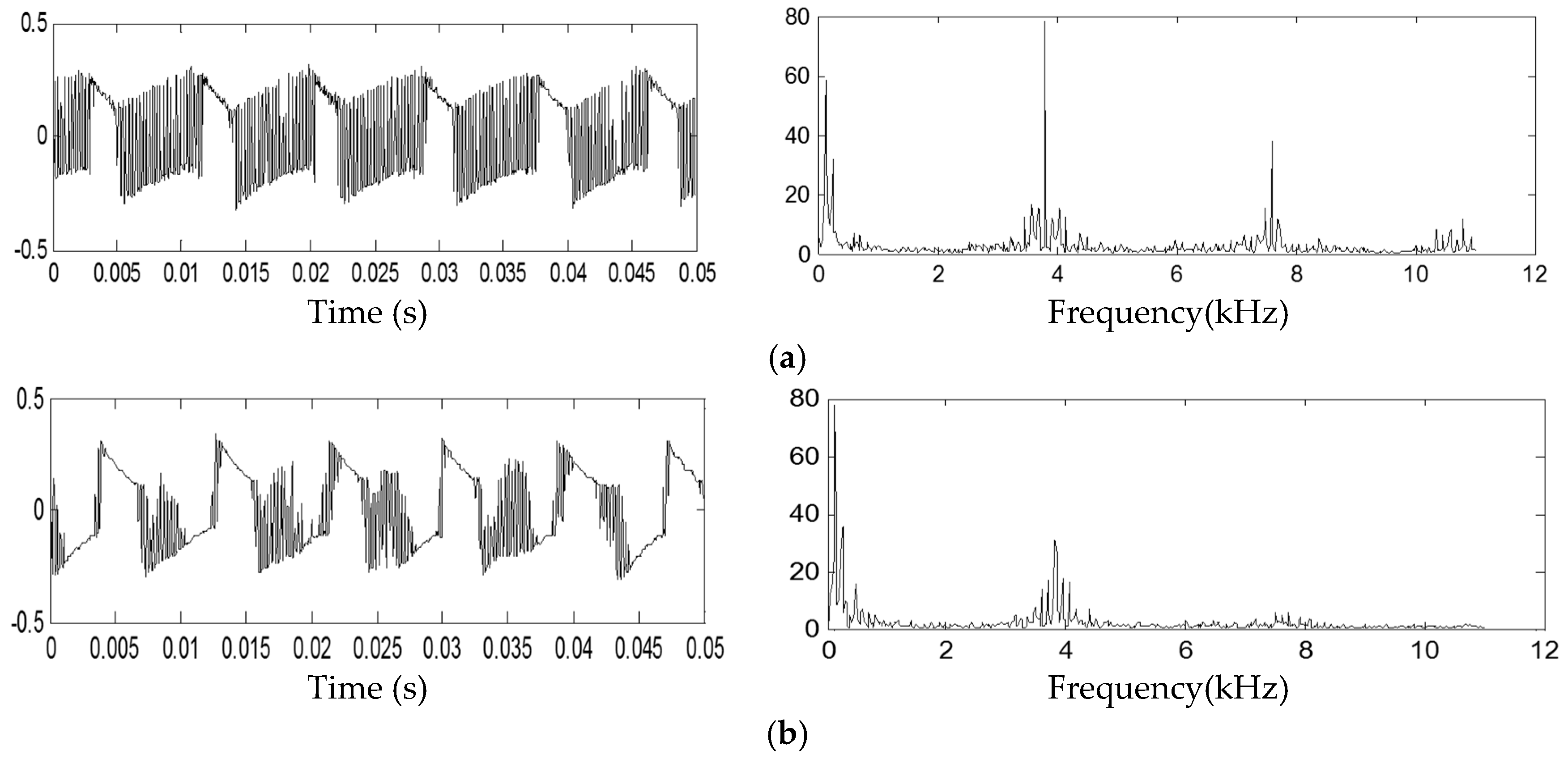
In order to verify the function of magnetic fluids for vibration suppression, magnetic fluids are filled in a hydraulic servovalve, selected due to the appearance of the self-excited noise in the servovalve. The self-excited noise is measured by a high-precision sound recording system including two microphones and associated software. The servovalve is installed on the experimental setup to test the static characteristics of servovalves, as shown in Figure 7. Pressure sensors are connected to the two chambers with nozzles. The flow rate meter is used to test the leakage flow rate or the flow rate between Port A and Port B when they are connected. When the supply pressure is 21 MPa, the self-excited noise can be obviously heard if the magnetic fluid is not filled in the servovalve. When magnetic fluids are filled in the working gaps of the torque motor in the servovalve, the self-excited noise is significantly reduced. The two power signals of the noise and their Fast Fourier Transformation (FFT) analysis results, both when magnetic fluids are applied in the servovalve and when they are not, are shown in Figure 8a,b, respectively. The waves are shown as the amplitude ratio, which is the tested sound pressure level ratio to a reference sound pressure level given by the recording software. FFT analysis results are also given together with the wave signals. From the FFT analysis in Figure 8a, it can be seen that the sound wave contains not only a low frequency component around 300 Hz, but also a high-frequency component with a frequency around 3.7 kHz. The high frequency component is supposed to be the self-excited noise, which coincides with the predicted vibration mode in Figure 5 and Table 2. The noise wave and FFT analysis results in Figure 8b show that the high-frequency noise is significantly depressed when magnetic fluids are applied.
6. Conclusions
From the simulation and experimental investigation above, it can be concluded that magnetic fluids can depress the self-excited vibration of armature and high-frequency noise inside a hydraulic servovalve by exerting damping forces on the armature due to the magnetic field of the torque motor. The mathematical models of the damping force from magnetic fluids can be expressed by a linear model with parameters calculated from the experimental data. Reasonable harmonic responses of the armature with magnetic fluids can be predicted when magnetic fluids are regarded as a spring and a damper if the mathematical models are used in the FEM analysis of the vibration mode.
Because the displacement of the armature is assumed to be small, the variation of magnetic strength inside the working gaps of the torque motor is neglected to make the modeling simple. However, the viscosity of magnetic fluids exposed to a magnetic field may also change slightly with the variation of magnetic field strength. Therefore, in the future, a better understanding of the suppression mechanism will be needed to investigate the influence of variation in the magnetic field strength on the viscosity of magnetic fluids that varies with the magnetic field strength inside the working gaps of the torque motor. Future work should also include exploring the influence of magnetic fluids with different volumes and the suppression effects due to magnetic fluids and other fluids with different properties.
Acknowledgments
The authors would like to give their acknowledgement to the financial support from the National Natural Science Foundation of China (No. 51675119).
Author Contributions
Wei Zhang, Jinghui Peng, and Songjing Li conceived and designed the experiments; Wei Zhang performed the simulation and experiments. Wei Zhang, Jinghui Peng, and Songjing Li analyzed the data; and Wei Zhang and Songjing Li wrote the paper.
Conflicts of Interest
The authors declare no conflict of interest.
References
- Lee, J.C.; Lee, W.H.; Lee, S.H.; Lee, S. Positive and negative effects of dielectric breakdown in transformer oil based magnetic fluids. Mater. Res. Bull. 2012, 47, 2984–2987. [Google Scholar] [CrossRef]
- Socoliuc, V.; Popescu, L.B. The role of the magnetically induced anisotropy of the pair correlation function in the dichroism of magnetic fluids. J. Magn. Magn. Mater. 2013, 347, 146–152. [Google Scholar] [CrossRef]
- Park, B.J.; Fang, F.F.; Choi, H.J. Magnetorheology: Materials and application. Soft Matter 2010, 6, 5246–5253. [Google Scholar] [CrossRef]
- Marinică, O.; Susan-Resiga, D.; Bălănean, F.; Vizman, D.; Socoliuc, V.; Vékás, L. Nano-micro composite magnetic fluids: Magnetic and magnetorheological evaluation for rotating seal and vibration damper applications. J. Magn. Magn. Mater. 2016, 406, 134–143. [Google Scholar] [CrossRef]
- Patel, J.; Parekh, K.; Upadhyay, R.V. Prevention of hot spot temperature in a distribution transformer using magnetic fluid as a coolant. Int. J. Therm. Sci. 2016, 103, 35–40. [Google Scholar] [CrossRef]
- Li, X.H.; Shinshi, T.; Hijikata, W.; Morimoto, Y. Development of a suspension type sliding planar motion table using magnetic fluid lubrication. Rev. Sci. Instrum. 2016, 87, 425–428. [Google Scholar] [CrossRef] [PubMed]
- Safarik, I.; Stepanek, M.; Uchman, M.; Slou, M.; Baldikova, E.; Nydlova, L.; Pospiskova, K.; Safarikova, M. Composite particles formed by complexation of poly(methacrylic acid)—Stabilized magnetic fluid with chitosan: Magnetic material for bioapplications. Mater. Sci. Eng. C 2016, 67, 486–492. [Google Scholar] [CrossRef] [PubMed]
- Safarik, I.; Maderova, Z.; Pospiskova, K.; Safarikova, M. Magnetic decoration and labeling of prokaryotic and eukaryotic cells. In Cell Surface Engineering: Fabrication of Functional Nanoshells; Fakhrullin, R.F., Ed.; RSC: Cambridge, UK, 2014; Volume 9, pp. 185–215. [Google Scholar]
- Ding, Y.; Li, D.C.; Wang, Q.L.; Zhang, H.N.; Zhang, Z.L. The experimental study of the Magnetic fluid damper based on the principle of second-order buoyancy. Key Eng. Mater. 2012, 512–515, 1459–1463. [Google Scholar] [CrossRef]
- Liu, J. Analysis of a porous elastic sheet damper with a magnetic fluid. J. Tribol.-Trans. ASME 2009, 131, 021801. [Google Scholar] [CrossRef]
- Ohno, K.I.; Suzuki, H.; Sawada, T. Analysis of liquid sloshing of a tuned magnetic fluid damper for single and co-axial cylindrical containers. J. Magn. Magn. Mater. 2011, 323, 1389–1393. [Google Scholar] [CrossRef]
- Oyamada, T.; Masuda, H.; Ikari, K.; Sawada, T. Damping characteristics of a magnetic fluid tuned liquid column damper under static magnetic fields. Int. J. Appl. Electromagn. Mech. 2014, 45, 659–665. [Google Scholar]
- Li, S.J.; Song, Y.W. Dynamic response of a hydraulic servo-valve torque motor with magnetic fluids. Mechatronics 2007, 17, 442–447. [Google Scholar] [CrossRef]
- Bateer, B.; Qu, Y.; Tian, C.G.; Du, S.; Ren, Z.; Wang, R.; Pan, K.; Fu, H. Facile synthesis of stable magnetic fluid using size-controlled Fe3O4 nanoparticles. Mater. Res. Bull. 2014, 56, 34–38. [Google Scholar] [CrossRef]
- Liu, Y.D.; Choi, H.J. Magnetorheology of core–shell typed dual-coated carbonyl iron particle fabricated by a sol–gel and self-assembly process. Mater. Res. Bull. 2015, 69, 92–97. [Google Scholar] [CrossRef]
- Zhang, L.; Huang, Z.; Shao, H.P.; Li, Y.; Zheng, H. Effects of γ-Fe2O3 on γ-Fe2O3/Fe3O4 composite magnetic fluid by low-temperature low-vacuum oxidation method. Mater. Des. 2016, 105, 234–239. [Google Scholar] [CrossRef]
- Li, Q.; Fannin, P.C.; Marin, C.N.; Malaescuc, I.; Rajd, K. On the utility of low frequency, polarized complex susceptibility measurements in the investigation of the dynamic properties of magnetic fluids. J. Mol. Liq. 2016, 219, 773–779. [Google Scholar] [CrossRef]
- Manukyan, S.; Schneider, M. Experimental investigation of wetting with magnetic fluids. Langmuir ACS J. Surf. Colloids 2016, 32, 5135–5140. [Google Scholar] [CrossRef] [PubMed]
- Zakinyan, A.; Mkrtchyan, L.; Dikansky, Y. Experimental investigation of surface instability of a thin layer of a magnetic fluid. Eur. J. Mech. B/Fluids 2015, 56, 172–177. [Google Scholar] [CrossRef]
- Zhao, M.; Hu, J.H.; Zou, J.B.; Zhao, B.; Li, Y. Characteristics of a magnetic fluid under an orthogonal alternating magnetic field. J. Magn. Magn. Mater. 2016, 409, 66–70. [Google Scholar] [CrossRef]
- Polunin, V.M.; Ryapolov, P.A.; Platonov, V.B.; Kuz’ko, A.E. Free oscillations of magnetic fluid in strong magnetic field. Acoust. Phys. 2016, 62, 313–318. [Google Scholar] [CrossRef]
- Hayashi, K.; Yamada, T.; Ido, Y. Resistance force of a shock absorber using magnetic functional fluids containing both micrometer-sized and nanometer-sized magnetic particles. Phys. Procedia 2010, 9, 243–247. [Google Scholar] [CrossRef]
- Peng, J.H.; Li, S.J.; Han, H. Damping properties for vibration suppression in electrohydraulic servo-valve torque motor using magnetic fluid. Appl. Phys. Lett. 2014, 104, 171905. [Google Scholar] [CrossRef]
- Gstöttenbauer, N.; Kainz, A.; Manhartsgruber, B.; Scheidl, R. Experimental and numerical studies of squeeze mode behaviour of magnetic fluid. Proc. Inst. Mech. Eng. Part C 2008, 222, 2395–2407. [Google Scholar] [CrossRef]
- Zhang, S.; Aung, N.Z.; Li, S. Reduction of undesired lateral forces acting on the flapper of a flapper–nozzle pilot valve by using an innovative flapper shape. Energy Convers. Manag. 2015, 106, 835–848. [Google Scholar] [CrossRef]
- Huang, J.; Wang, P.; Wang, G. Squeezing force of the magnetorheological fluid isolating damper for centrifugal fan in nuclear power plant. Sci. Technol. Nucl. Install. 2012, 2012, 175703. [Google Scholar] [CrossRef]
Figure 1.
Construction and working mode of the torque motor with magnetic fluids. (a) Construction; (b) the working mode of magnetic fluids.
Figure 1.
Construction and working mode of the torque motor with magnetic fluids. (a) Construction; (b) the working mode of magnetic fluids.
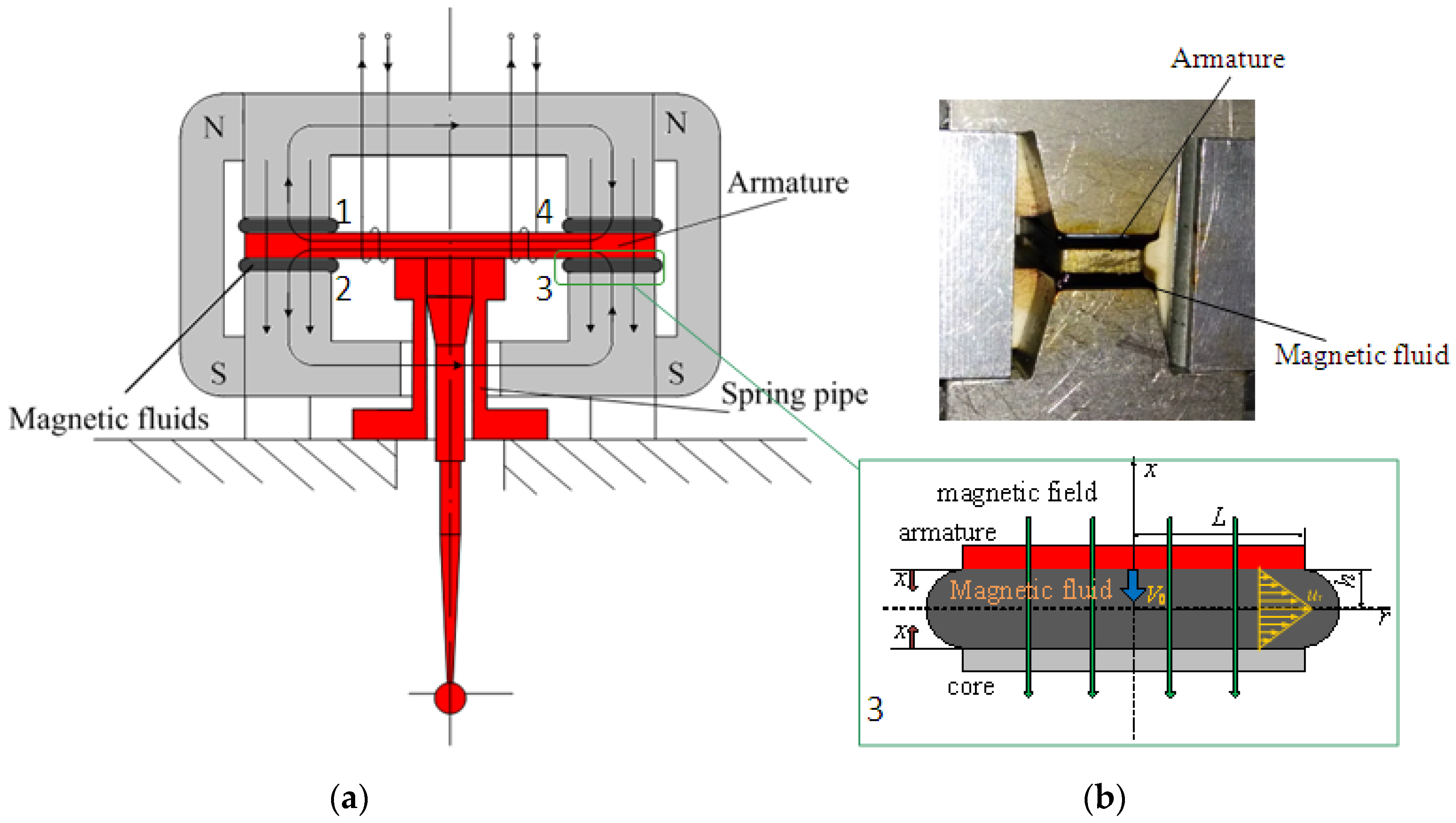
Figure 2.
Damping force vs. squeezing displacement under different squeezing velocities.
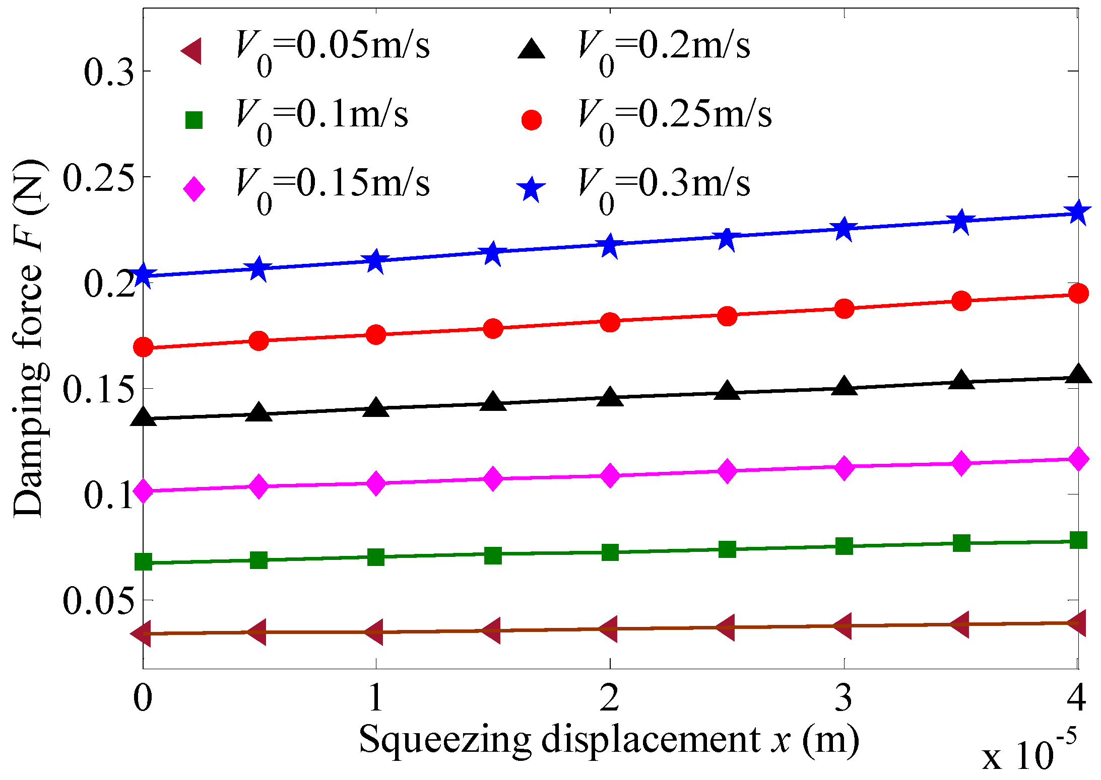
Figure 3.
Simulated and tested model of the armature. (a) Geometric model of the armature; (b) the tested sample of the armature.
Figure 3.
Simulated and tested model of the armature. (a) Geometric model of the armature; (b) the tested sample of the armature.

Figure 4.
Experimental setup for vibration testing of the armature.

Figure 5.
Predicted harmonic responses in the x-direction (with and without magnetic fluids). (a) Predicted harmonic responses (0–2000 Hz); (b) predicted harmonic responses (2000–4500 Hz).
Figure 5.
Predicted harmonic responses in the x-direction (with and without magnetic fluids). (a) Predicted harmonic responses (0–2000 Hz); (b) predicted harmonic responses (2000–4500 Hz).
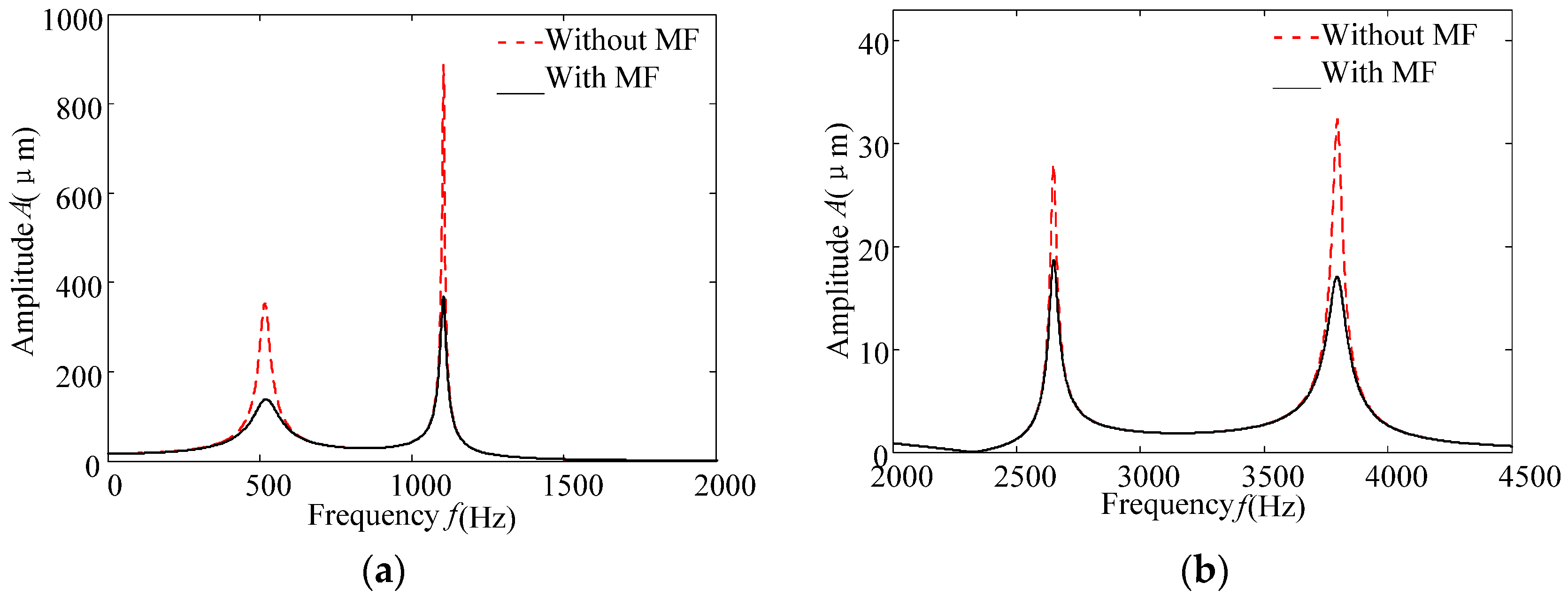
Figure 6.
Tested harmonic responses in the x-direction (with and without magnetic fluids). (a) The tested harmonic responses (0–2000 Hz); (b) the tested harmonic responses (2000–4500 Hz).
Figure 6.
Tested harmonic responses in the x-direction (with and without magnetic fluids). (a) The tested harmonic responses (0–2000 Hz); (b) the tested harmonic responses (2000–4500 Hz).

Figure 7.
Experimental setup for self-excited noise and the tested servovalve with magnetic fluids. (1) Hydraulic pump; (2) relief valve; (3) tested servovalve with or without MF; (4) pressure gauge; (5) pressure sensor; (6) flow rate meter; (7) back pressure valve; (8) cooler; (9) computer with acquisition systems; (10) sound sensor.
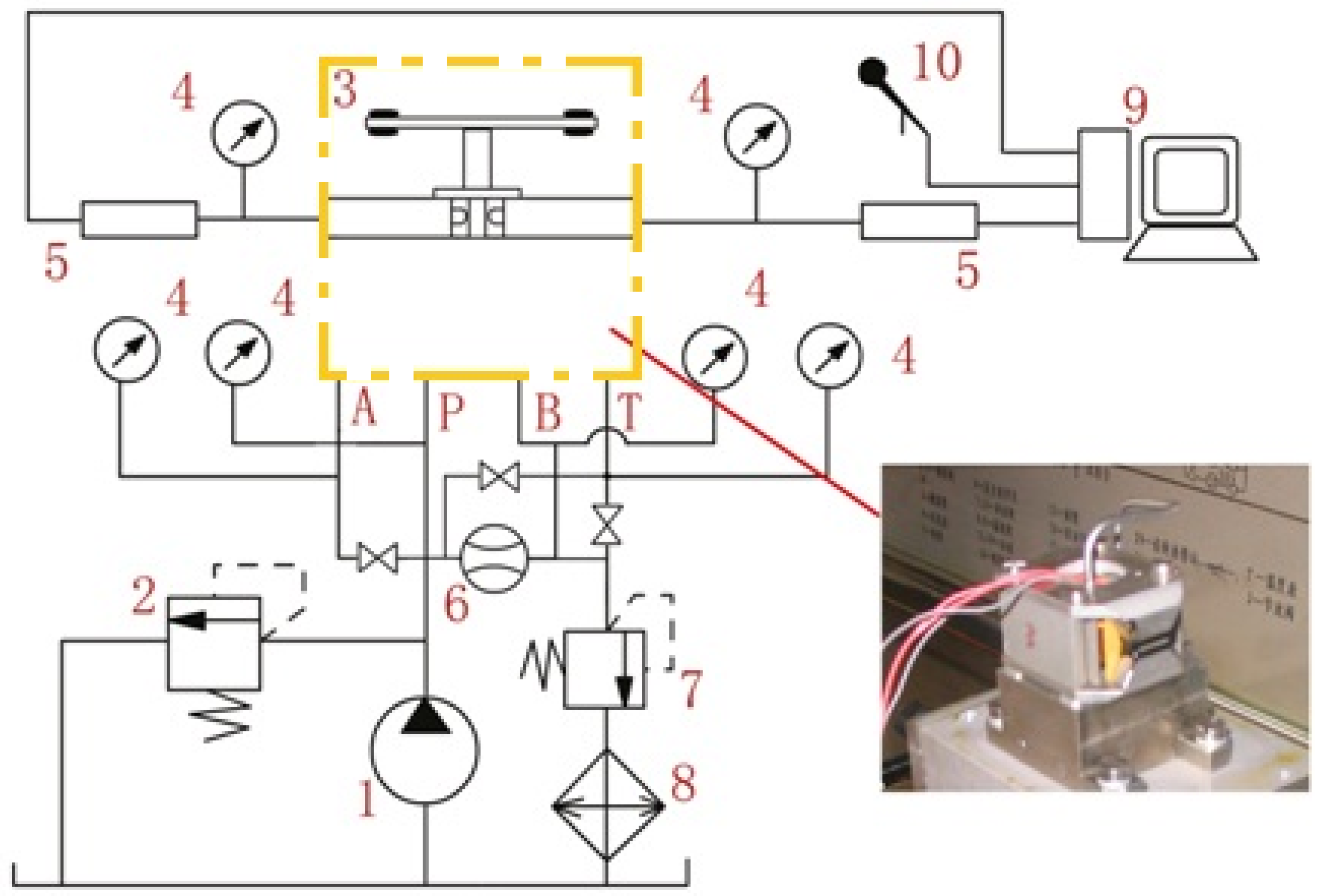
Figure 8.
Tested results of self-excited noise inside the servovalve. (a) The tested noise wave and FFT analysis results without magnetic fluids; (b) the tested noise wave and FFT analysis results with magnetic fluids.
Figure 8.
Tested results of self-excited noise inside the servovalve. (a) The tested noise wave and FFT analysis results without magnetic fluids; (b) the tested noise wave and FFT analysis results with magnetic fluids.


Table 1.
The magneto-viscosity parameters of a magnetic fluid under saturated conditions.
| Parameters | Value |
|---|---|
| Dynamic yield stress (Pa) | 6.168 |
| Yield stress (Pa) | 6.23 |
| Viscosity at yielding zone (Pa·s) | 0.0776 |
| Viscosity at unyielding zone (Pa·s) | 7.76 |
Table 2.
Comparison between the predicted resonance peaks at the end of the feedback rod with and without magnetic fluids.
Table 2.
Comparison between the predicted resonance peaks at the end of the feedback rod with and without magnetic fluids.
| Order | Without Magnetic Fluid | With Magnetic Fluid | Suppression (%) | ||
|---|---|---|---|---|---|
| Resonance Peak (μm) | Damping Ratio (%) | Resonance Peak (μm) | Damping Ratio (%) | ||
| 1 | 351.9 | 3.29 | 138.1 | 8.26 | 60.8 |
| 4 | 886.3 | 0.34 | 369.99 | 0.82 | 58.4 |
| 6 | 27.92 | 0.45 | 18.71 | 0.67 | 33.0 |
| 9 | 32.36 | 0.51 | 17.09 | 0.97 | 47.2 |
© 2017 by the authors. Licensee MDPI, Basel, Switzerland. This article is an open access article distributed under the terms and conditions of the Creative Commons Attribution (CC BY) license (http://creativecommons.org/licenses/by/4.0/).
Share and Cite
MDPI and ACS Style
Zhang, W.; Peng, J.; Li, S. Damping Force Modeling and Suppression of Self-Excited Vibration due to Magnetic Fluids Applied in the Torque Motor of a Hydraulic Servovalve. Energies 2017, 10, 749. https://doi.org/10.3390/en10060749
AMA Style
Zhang W, Peng J, Li S. Damping Force Modeling and Suppression of Self-Excited Vibration due to Magnetic Fluids Applied in the Torque Motor of a Hydraulic Servovalve. Energies. 2017; 10(6):749. https://doi.org/10.3390/en10060749
Chicago/Turabian StyleZhang, Wei, Jinghui Peng, and Songjing Li. 2017. "Damping Force Modeling and Suppression of Self-Excited Vibration due to Magnetic Fluids Applied in the Torque Motor of a Hydraulic Servovalve" Energies 10, no. 6: 749. https://doi.org/10.3390/en10060749
Note that from the first issue of 2016, this journal uses article numbers instead of page numbers. See further details here.