1. Introduction
In recent years, reliability, continuity, and fault-related issues have been receiving lots of research attention in automation or industrial processes employing a pulse width modulation (PWM) inverter-fed permanent magnet synchronous machine (PMSM) drive systems. Furthermore, in some drive applications such as vehicle and railway transportation, a high degree of reliability and safety must be continuously achieved, even in accident or fault situations, which makes the fault diagnosis of AC machine drive systems as one of the primary concerns [
1]. Since a fault in such applications often leads to a critical problem, as well as increased losses caused by abrupt system operation halts, there has been a strong need to enhance the system stability and sustainability.
In general, PWM inverter-fed PMSM drive systems are usually subject to various faults in different system components such as the power converter module, controller, and sensing devices [
2]. The faults in drive systems often trigger a reduced system lifetime and high repair costs due to unscheduled maintenance, eventually causing disastrous accidents in an extreme case. For this reason, a considerable number of studies has been devoted to developing fault diagnosis schemes. The main objective is to realize online fault detection and fault localization algorithms without requiring any additional hardware components or extra sensors. Other desirable requirements are speed, simplicity, and easiness in the algorithm to such an extent that the diagnosis scheme can be installed in a commercial drive system without requiring much computational burden and a large amount of CPU resources.
Recently, several survey papers have reviewed the faults in drive systems with statistical approaches. According to a recent industry study, power components and gate control circuits are known to be the components most susceptible to failure in electric machine drive systems [
3,
4]. In particular, it has been estimated that about 38% of the faults in industrial AC drives are due to failures of semiconductor power devices. The average downtime cost in different industries caused by unscheduled maintenance events has been investigated [
5]. The propensity of several faults occurring in AC machine drives has been analyzed in detail. According to this study, it is known that 63% of the users experience the faults in drive systems in the first 12 months of operation. In particular, 70% of these faults are related to the failures in power components [
6]. The behavior of a voltage source inverter-fed induction machine drive has been investigated considering key fault conditions in the converter [
7]. In recent times, the researches on fault diagnosis scheme have been steadily expanding into the application areas such as the grid-connected inverters [
8], renewable energy systems [
9], and electric or hybrid vehicles [
10].
A failure in semiconductor power devices are classified as a short-circuit fault or an open-circuit fault. The short-circuit fault is more critical and requires immediate measures to shut down the system. Most of the short-circuit detections and protections depend on hardware-based methods since the time between the fault initiation and failure is very small. On the other hand, the open-circuit fault does not essentially make the system shut down. However, this fault may lead to a severe secondary fault in the drive system due to electrical and thermal stresses if it remains undetected for a long time, eventually resulting in system outages and high repair costs [
11].
There have been intensive studies regarding the development of fault-tolerant systems to allow the continuity of system operation over the last years [
11,
12,
13]. A fault-tolerant routine is generally accomplished in four main steps, which are the fault detection, including the identification of fault location, the isolation of faulty components, hardware reconfiguration, and post-fault control optimization. Following these procedures, a fault-tolerant control of three-phase power converter for a PMSM has been studied in a fully automated way by connecting the isolated motor phase to the midpoint of the capacitor bank in DC link [
13]. The success of a fault-tolerant system is mainly dependent upon the precision and speed of both the fault detection and identification of the fault location. However, this scheme usually requires large back-up equipment to replace a damaged component in the stage of hardware reconfiguration, which is often the cause of increased cost, size, and complexity of the system. Moreover, available system output may be significantly reduced in post-fault operation. Thus, a rapid and proper action with the knowledge of exact fault location can be a more practical and simpler alternative in a commercial drive system.
The fault detection methods can be categorized as current-based approaches, voltage-based approaches, observer-based techniques, and intelligent control methods such as the fuzzy logic and knowledge-based models. The current-based approaches use average current Park’s vector [
14], current residual vector between the estimator and system [
15], pattern of the stator currents by constructing a signature vector in the
dq frame [
16], or the normalized DC current to consider load currents [
17]. Other methods detect open-switch faults by using the average value of reference current errors [
18]. Also, the fault detection based on the average absolute values of normalized currents has been presented to implement the detection irrespective of operating conditions [
19,
20]. Other studies have considered the simultaneous open faults in inverter multiple switches and detected fault occurrence by using the current harmonics [
1,
21], moving window-based current signals [
22], and non-zero phase current information [
23].
Alternative fault diagnosis methods use a voltage-based approach for open-switch fault detection. To judge the fault occurrence, the measured voltage errors between the normal inverter and faulty case have been employed [
24]. Also, a fault diagnosis method using the sectoral average residuals of the pole voltages has been presented in order to improve the performance of the voltage measurement-based methods [
25]. The fault detection based on the measurement of the pole voltage and its duration time has been reported for neutral-point-clamped inverter [
26]. A fault detection circuit for insulated-gate bipolar transistors (IGBT) based on the gate voltage behavior has been presented [
27]. However, the usage of voltage sensors increases the cost and complexity of the detection system. Alternatively, in order to simplify the detecting circuits and get rid of the requirement of high cost voltage sensors, collector-emitter voltages of the lower power switches in inverter have been acquired indirectly by using a high speed diagnostic photocoupler [
28]. Other scheme use field-programmable gate arrays (FPGAs) for fault diagnosis of power converters [
29]. However, the requirement of extra sensors or components is not desirable in industrial drive applications. Thus, fault diagnosis methods without requiring any extra sensors or hardware have been also investigated by using the operating characteristic of machines [
30] or by comparing the normalized reference voltages and estimated voltages [
31].
Instead of using the current or voltage-based approaches, other fault diagnosis methods use an observer-based technique [
32], the wavelet transformation-based switching faults detection [
33], model-based approach [
34], and a model reference adaptive system (MRAS) [
35]. These techniques are preferred in industrial applications because they do not require the installation of extra hardware. However, the model-based approaches such as observer or MRAS scheme usually require sufficiently accurate information on all the system parameters.
Other approaches use an intelligent control method such as fuzzy logic [
36] and knowledge-based models [
12] for fault detection. However, these methods have a major drawback of large computational burden due to the complexity of the diagnosis algorithms. Consequently, the adoption of such algorithms in a standard drive system is not easy.
The open-switch faults in an inverter often occur in a very complicated manner. Due to this reason, it was only recently in a few references that real-time diagnosis schemes for open-switch faults in multiple switches have been presented. Even though the fault detection is simple and immediate, the exact fault localization is not simple task, especially when open faults in three multiple switches occur in various types of combination because different open-switch fault locations may develop the same fault signature. Hence, until now conventional diagnosis methods confine the fault localization problem to only the case of the open faults in two simultaneous switches [
1,
16,
18,
19,
28,
35] due to the complexity and precision issues in the case of open faults in more than two switches, even though this is not generally the case.
In order to overcome the limitations in the existing methods, this paper proposes a reliable and practical on-line fault localization scheme for a PWM inverter-fed PMSM drive system, even when the inverter has simultaneous open faults in up to three switches. An open-switch fault is usually initiated by an accidental over-current or electrical and thermal stresses. This fault may induce crucial secondary damage in the drive system since it is easily propagated and produce a continuous harmful effect on other system components. To overcome the limitation in the conventional diagnosis methods and to avoid the complexity in fault localization, the open faults in multiple switches are classified in seven different categories. By using the fault signature developed by each seven fault group as well as by introducing free-wheeling mode detection, the open faults in multiple switches can be identified in a reliable and systematic way. In addition, rather than confining the number of simultaneous open-switches to only two, the proposed scheme aims to extend the open fault problem in multiple switches into a general case. The main objective is to realize a rapid and reliable online fault localization algorithm under the condition of simultaneous open-switches (up to three) without requiring any extra hardware or sensors in order that the algorithm can be easily installed in the main CPU of a commercial drive system. The entire fault diagnosis scheme is implemented on a digital controller by using a TMS320F28335digital signal processor (DSP) [
37]. The experimental results for various scenarios of open faults in multiple switches to verify the usefulness of the proposed open-switch fault localization scheme.
2. Open-Switch Faults in a PWM Inverter
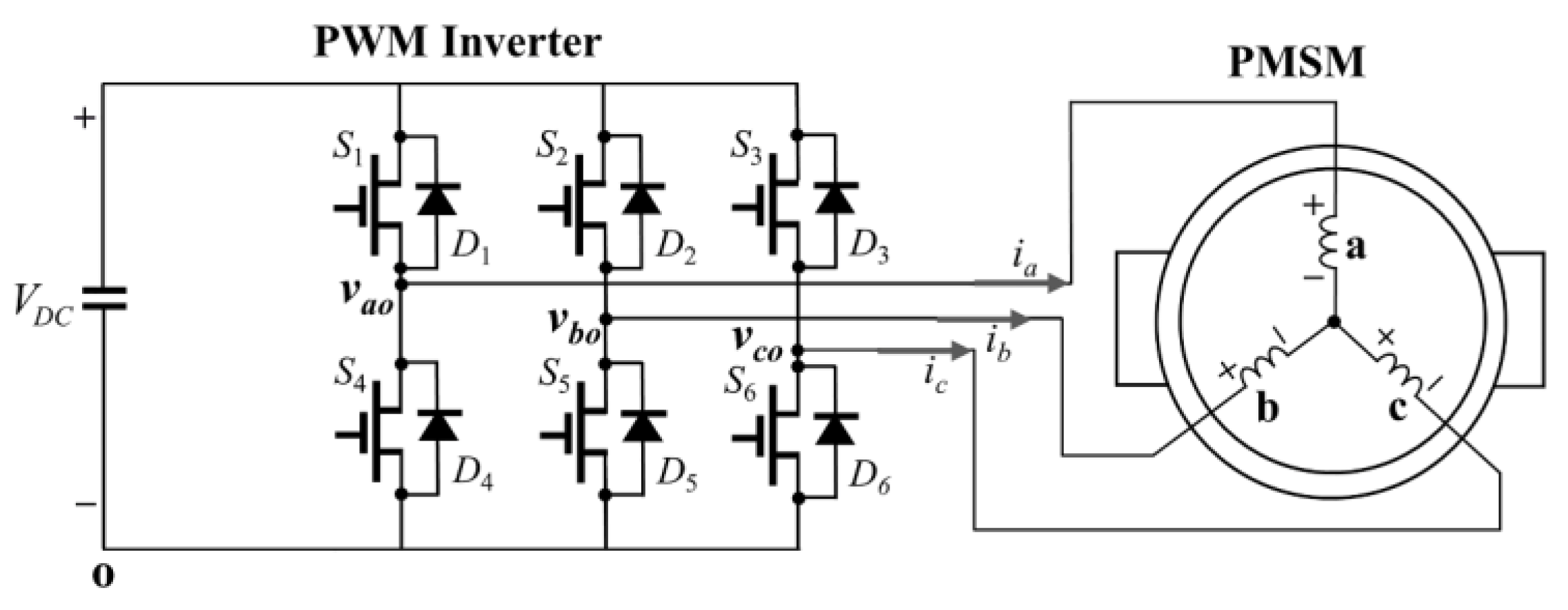
Figure 1 shows the configuration of a three-phase PWM inverter-fed PMSM drive system, in which the PWM inverter consists of six active switches and six free-wheeling diodes. In this figure,
Sx and
Dx denote the symbol of switches and diodes for
x = 1, 2, … 6, and
νao,
νbo and
νco represent the terminal voltages. Whereas the terminal voltages are uniquely determined only by the switching function under the normal operating condition without open-switch fault, they are dependent on the direction of phase current under the open-switch fault condition [
35]. Detailed analysis regarding the terminal voltage deviation according to the conduction of free-wheeling diode under the open-switch fault is presented in [
23,
35].
The deviation in terminal voltages caused by the open-switch fault directly influences the generation of phase currents. Since it distorts sinusoidal phase currents, the current waveform can be useful to detect the fault occurrence as well as its location. For example, when the open-switch fault occurs in switch S1, positive a-phase current can flow only through D4 path, making the terminal voltage νao equal to zero. Since the terminal voltage with VDC cannot be applied to a-phase, there are no positive current waveforms in a-phase.
In general, commercial AC machine drive systems are implemented with only phase current sensing devices without voltage measurement devices. Thus, to adopt the fault detection and fault localization algorithm in a practical drive system, it is often preferred to realize the fault diagnosis scheme by using only the current information on an online basis. One of the important issues in the fault diagnosis scheme of an inverter-fed PMSM drive is the early detection of faults before the fault expands widely to other components due to the current and thermal stresses as well as mechanical vibration. Another important issue is to find out its source or location correctly without “false alarms”.
The open-switch faults in inverters often occur in a very complicated manner. Especially, when open faults occur in multiple switches in various types of combination, exact fault localization is not easy because different open fault locations may present the same fault signature. Due to this complexity, the existing diagnosis methods confine the fault localization problem to the case of the open faults in two simultaneous switches. In order to overcome this limitation, this paper deals with a reliable open fault localization method for up to three simultaneous open-switches. In addition, for the purpose of alleviating the complexity in diagnosis algorithm, the open faults in multiple switches up to three are classified into seven different groups. Because each fault group produces unique fault signature in phase current waveforms, the decision-making process to identify faulty switches is more straightforward and systematic. For this aim, the open-switch faults are categorized as seven fault groups in this paper, which are expressed as follows:
FG1 = {(S1), (S2), (S3), (S4), (S5), (S6)}
FG2 = {(S1 S4), (S2 S5), (S3 S6)}
FG3 = {(S1 S5), (S1 S6), (S2 S4), (S2 S6), (S3 S5), (S3 S4)}
FG4 = {(S1 S2), (S1 S3), (S2 S3), (S4 S5), (S4 S6), (S5 S6)}
FG5 = {(S1 S2 S6), (S1 S3 S5), (S1 S5 S6), (S2 S3 S4), (S2 S4 S6), (S3 S4 S5)}
FG6 = {(S1 S4 S2), (S1 S4 S3), (S2 S5 S1), (S2 S5 S3), (S3 S6 S1), (S3 S6 S2)}
FG7 = {(S1 S4 S5), (S1 S4 S6), (S2 S5 S4), (S2 S5 S6), (S3 S6 S4), (S3 S6 S5)}
where FG1 through FG7 denote seven different fault groups according to the number and position of faulty switches, respectively, and the variables in parenthesis denote all elements in each fault group. In these fault groups, the group FG1 denotes the open fault in single switch. The fault groups FG2 through FG4 represent the open fault in two simultaneous switches and these groups are further divided according to the location of the two faulty switches. The group FG2 has the open fault in all the switches of a one-phase inverter leg. In the group FG3, one of two open-switches occurs in the upper leg and the other in the lower leg. On the other hand, the group FG4 has two open-switches either only in the upper leg or only in the lower leg. The fault groups FG5 through FG7 represent the open fault in three simultaneous switches depending on the location of the faulty switches. In the group FG5, the open-switches occur in three different inverter legs. The group FG6 has three open-switches in the entire switches of one-phase inverter leg with one additional upper switch. On the other hand, the group FG7 has three open-switches in the entire switches of one-phase inverter leg with one additional lower switch. Depending on the number and position of faulty switches, each group has a different fault signature in the phase current waveforms.
Even though the open-switch fault detection is simple and immediate, the realization of a reliable faulty switch localization scheme is not a simple task because the open-switch faults occur in a very complicated manner with various combinations of multiple switches. Even, some simultaneous open-switches occurring in different locations may produce exactly the same fault signature in phase current waveforms.
Figure 2 and
Figure 3 show the experimental results for this case.
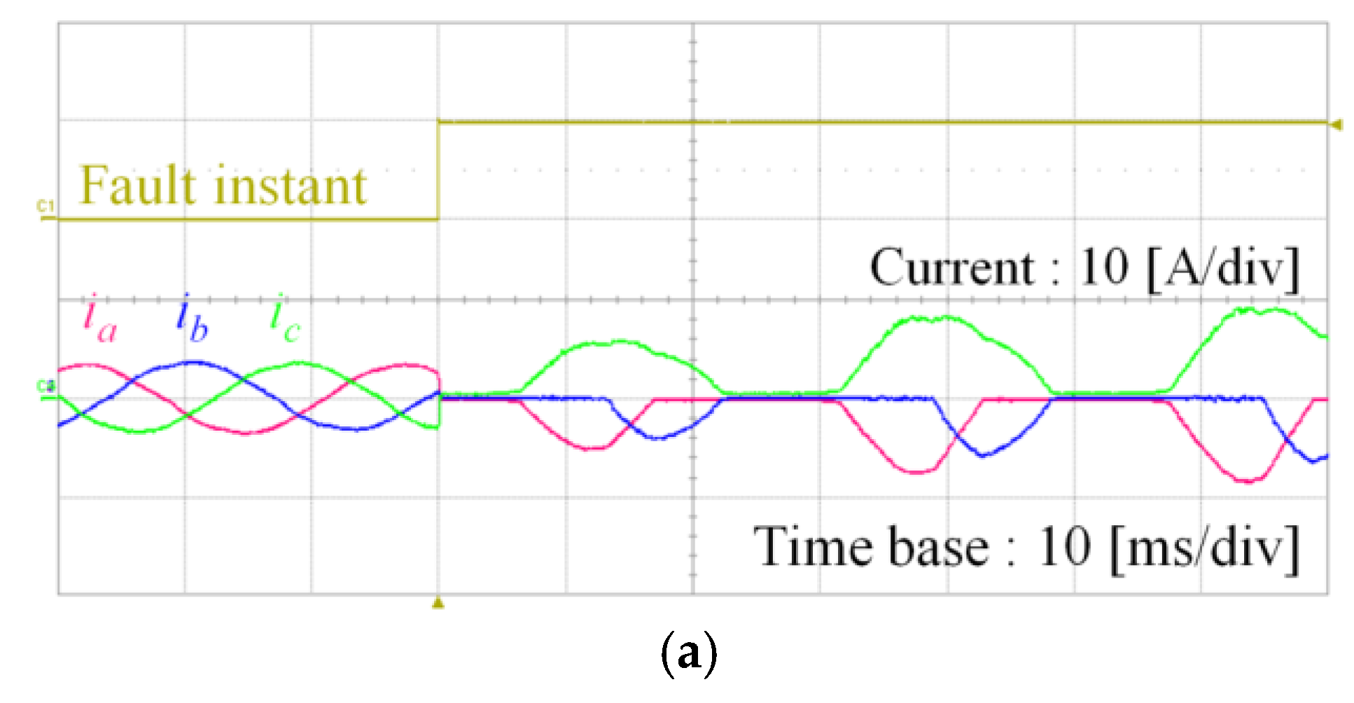
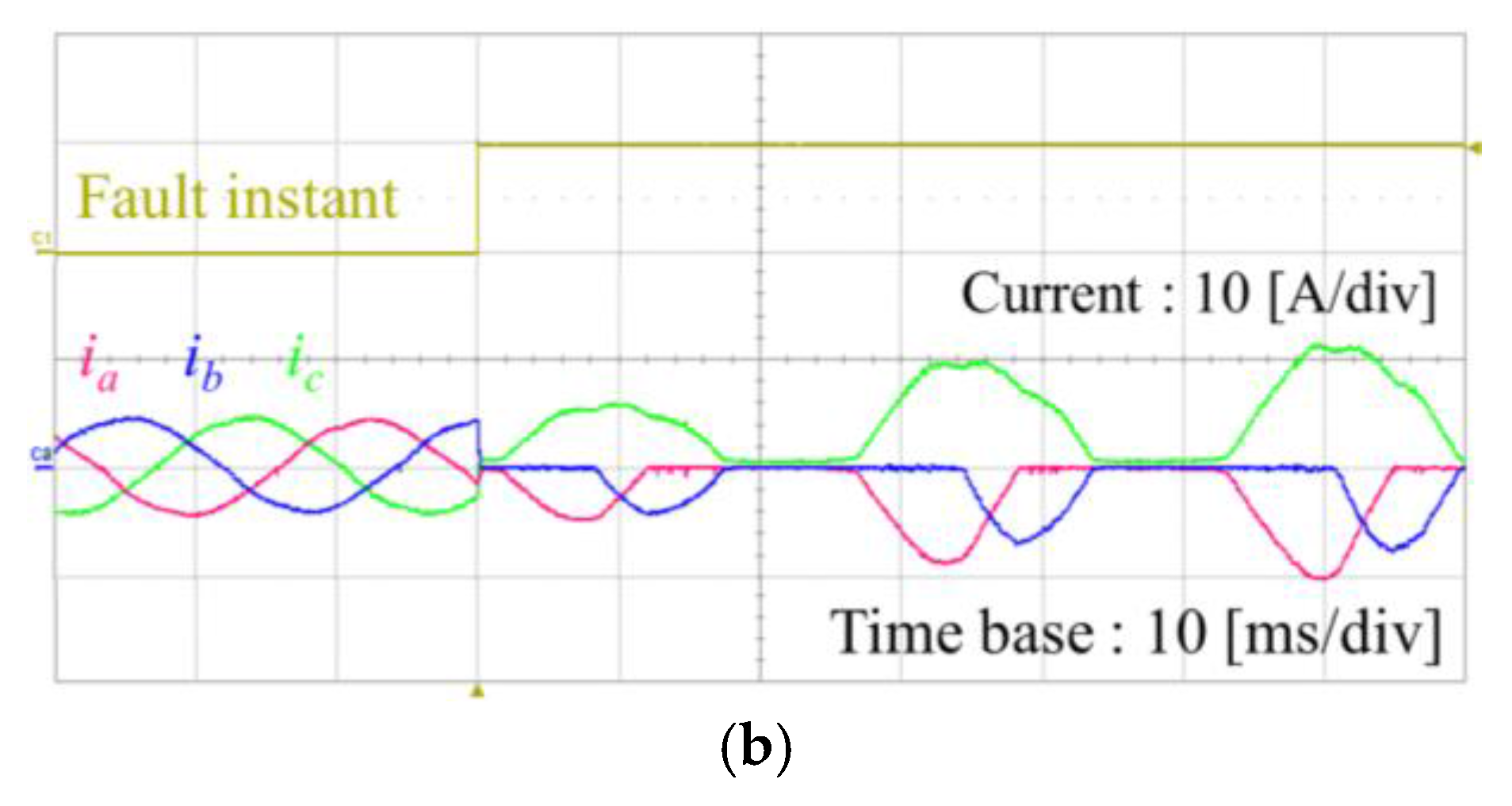
Figure 2 shows the experimental results for three-phase currents under the simultaneous open-switch faults in
S1 and
S2 of FG
4, and under the simultaneous open-switch faults in
S1,
S2 and
S6 of FG
5, respectively. It is clearly observed that these different faults provide the same three-phase current waveforms. For both the cases, positive
a-phase and positive
b-phase currents cannot flow due to the open-switch faults in
S1 and
S2. In addition, negative
c-phase current does not exist regardless of the open-switch fault in
S6 due to the absence of positive current supply through both
a-phase and
b-phase. As a result, positive
a-phase and
b-phase currents as well as negative
c-phase current are absent in either case, even if the open-switch faults occured in different locations.
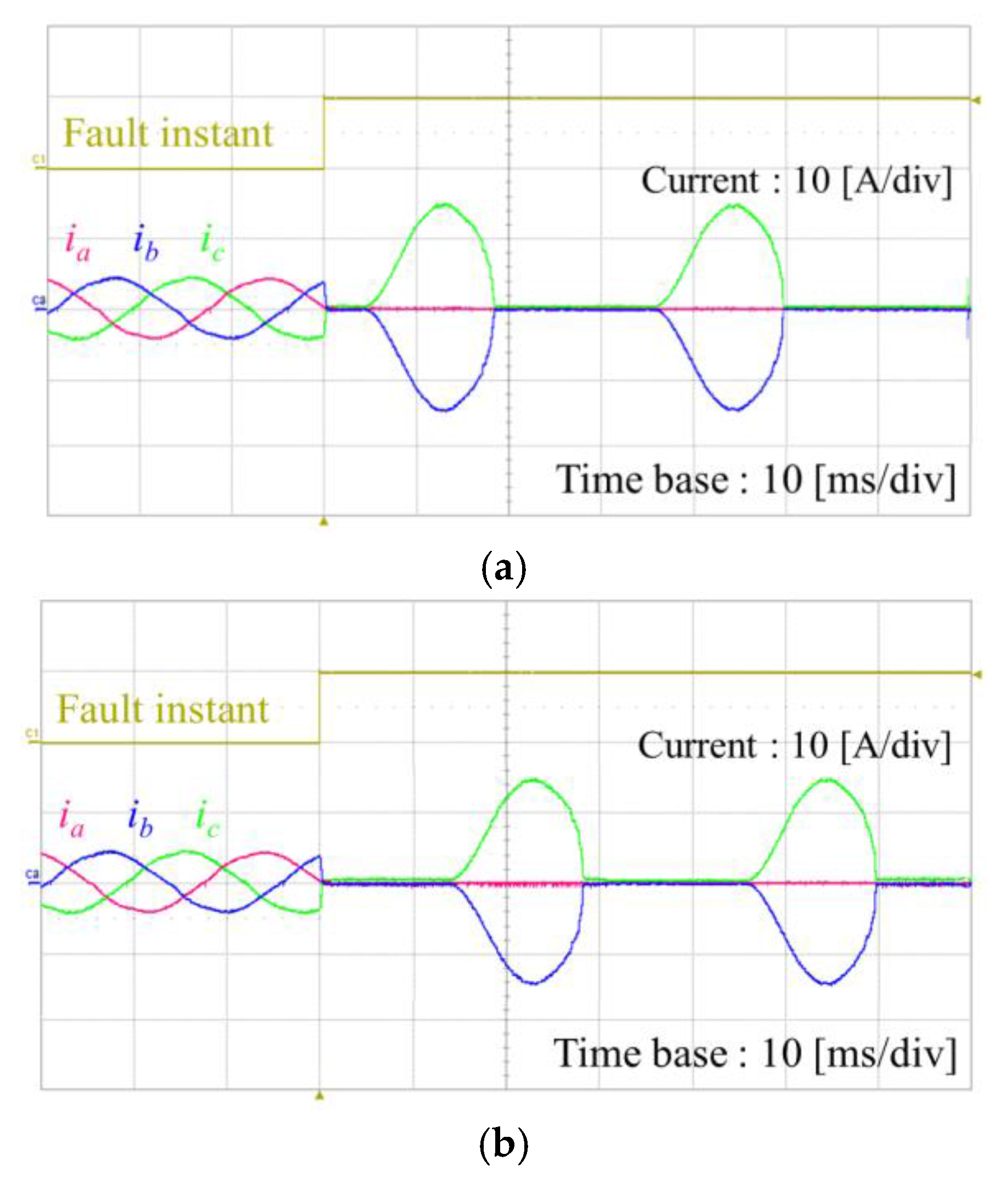
Figure 3 shows the experimental results for three-phase currents under the simultaneous open-switch faults in
S1,
S2 and
S4 of FG
6, and under the simultaneous open-switch faults in
S1,
S4 and
S6 of FG
7, respectively. These two fault conditions have the open faults in
S1 and
S4 in common. Due to the open faults in the entire switches of
a-phase leg, the inverter cannot develop
a-phase current, making
b-phase and
c-phase the only possible path for the current. Under the simultaneous open-switch faults in
S1,
S2 and
S4, positive
b-phase current cannot flow due to the open-switch in
S2. Additionally, negative
c-phase current does not exist due to the absence of positive current supply through
b-phase. As a result, positive
c-phase and negative
b-phase currents are only possible under the simultaneous open-switch faults in
S1,
S2 and
S4 as shown in
Figure 3a. Similar analysis can be applied for the simultaneous open-switch faults in
S1,
S4 and
S6. In this condition, there are no
a-phase current and no negative
c-phase current as well, due to open-switch. Additionally, positive
b-phase current does not exist due to the absence of negative current path. Thus, as shown in
Figure 3b, positive
c-phase and negative
b-phase currents are only possible, which is very similar to the result in
Figure 3a.
In addition to these results in
Figure 2 and
Figure 3, it is worth mentioning that all the fault conditions in FG
4 have their counterparts in FG
5 in view of giving exactly the same fault signature in phase current waveforms. In other words, one fault condition in FG
4 has the same fault signature with one in FG
5. Similarly, all the fault conditions in FG
6 have their counterparts in FG
7 in view of producing the same fault signature in current. Due to this similarity and complexity, the implementation of a reliable faulty switch localization scheme is a challenging task.
Table 1 summarizes the fault conditions giving the same fault signature in current between FG
4 and FG
5, and between FG
6 and FG
7, respectively.
4. Proposed Fault Localization Scheme for Simultaneous Open-Switches
In this section, the proposed fault localization scheme for an inverter open-switch fault is described. The purpose is for the main controller to identify faulty switches reliably without human inference only by observing the fault signature in currents developed by seven fault groups. To localize faulty switches in an expeditious way, the fault group is first identified. According to the analysis in
Section 2, positive phase currents flow through the conduction of inverter upper switches
S1,
S2 and
S3, and negative phase currents through the conduction of inverter lower switches
S4,
S5 and
S6. Thus, if
Nnzc is defined as the number of positive and negative current waveforms in each phase within the entire period, the fault group can be basically identified by using
Nnzc, in spite of some exceptional cases. During the normal non-fault condition, the number of positive and negative current waveforms,
Nnzc becomes 6 because all the positive and negative current waveforms exist in three-phase. However, this value is reduced under open fault conditions depending on the number and position of open-switches. For example, under the open fault in single switch
S1, which corresponds to FG
1,
Nnzc becomes 5 because only the positive
a-phase current is absent.
The fault groups FG2 and FG3 have Nnzc equal to 4 because two positive or negative current waveforms are missing. In these cases, by considering that one phase current always remains zero in the fault group FG2 in which the entire switches in one inverter leg have the open faults, these two groups can be easily distinguished by using In,norm in Equation (1).
In the fault groups FG
4 and FG
5,
Nnzc is equal to 3. Even if the number of simultaneous open-switches is two in the fault group FG
4,
Nnzc is equal to 3 rather than 4 according to the analysis in
Figure 2. The fault group FG
4 has two open-switches either only in the upper leg or only in the lower leg. Since two open-switches in the upper leg prevent negative current in the other phase and two open-switches in the lower leg prevent positive current in the other phase,
Nnzc becomes 3 in the fault group FG
4. As explained in
Figure 2 and
Table 1, two fault groups FG
4 and FG
5 provide exactly the same fault signature in view of three-phase current waveforms. Thus, the exact fault group identification and faulty switch localization are not possible by using only the conventional methods. To overcome this limitation, this paper introduces a free-wheeling mode detection for the purpose of distinguishing these two fault groups.
Due to the similar analysis, the fault groups FG
6 and FG
7 have
Nnzc equal to 2. Even if the number of simultaneous open-switches is three for both the groups,
Nnzc becomes 2 rather than 3 according to the analysis in
Figure 3. These two groups have the open fault in the entire switches of one-phase inverter leg with one additional switch in upper or lower side. Definitely, entire open-switches of one-phase inverter leg yield zero current in that phase. In addition to that, one additional upper open-switch prevents negative current in other phase, and vice versa. As explained in
Figure 3 and
Table 1, two fault groups FG
6 and FG
7 provide exactly the same fault signature in view of three-phase current waveforms. Similarly, a free-wheeling mode detection is employed to distinguish these two fault groups.
Table 2 summarizes the identification of the fault group in the proposed localization scheme by using the number of positive and negative current waveforms. To identify the fault group, the phase-current information processed with the moving window is employed. As a result, the diagnosis variables are updated at each sampling instant to constitute the recently acquired periodic data in one window length. This permits a rapid update on the diagnosis variables as compared with the method processing the current data only after the entire periodic data is acquired.
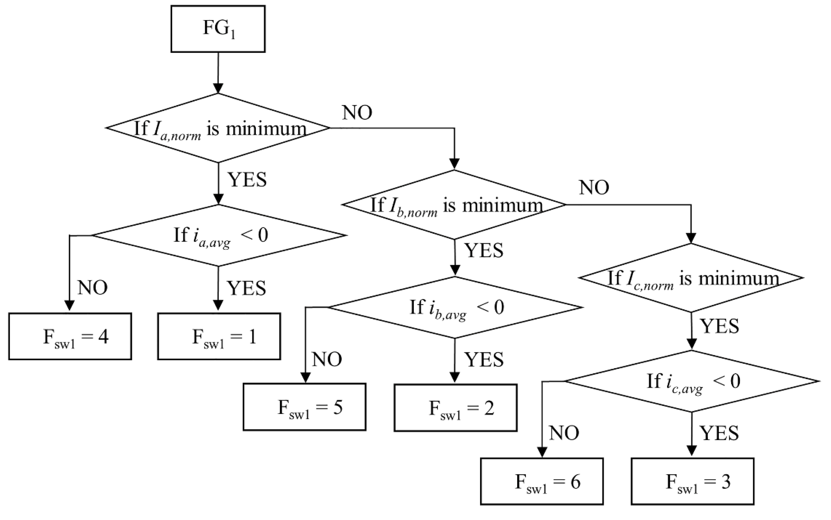
Once the fault group is identified, the faulty switches are detected by using the fault signature developed by each group. In the fault group FG
1, the identification of faulty switch can be easily accomplished by finding absent positive or negative current in each phase. For example, under the open-switch fault in
S1, positive
a-phase current is absent.
Figure 5 shows the detection of faulty switch in FG
1, where
ia,avg,
ib,avg, and
ic,avg denote three-phase average currents, respectively.
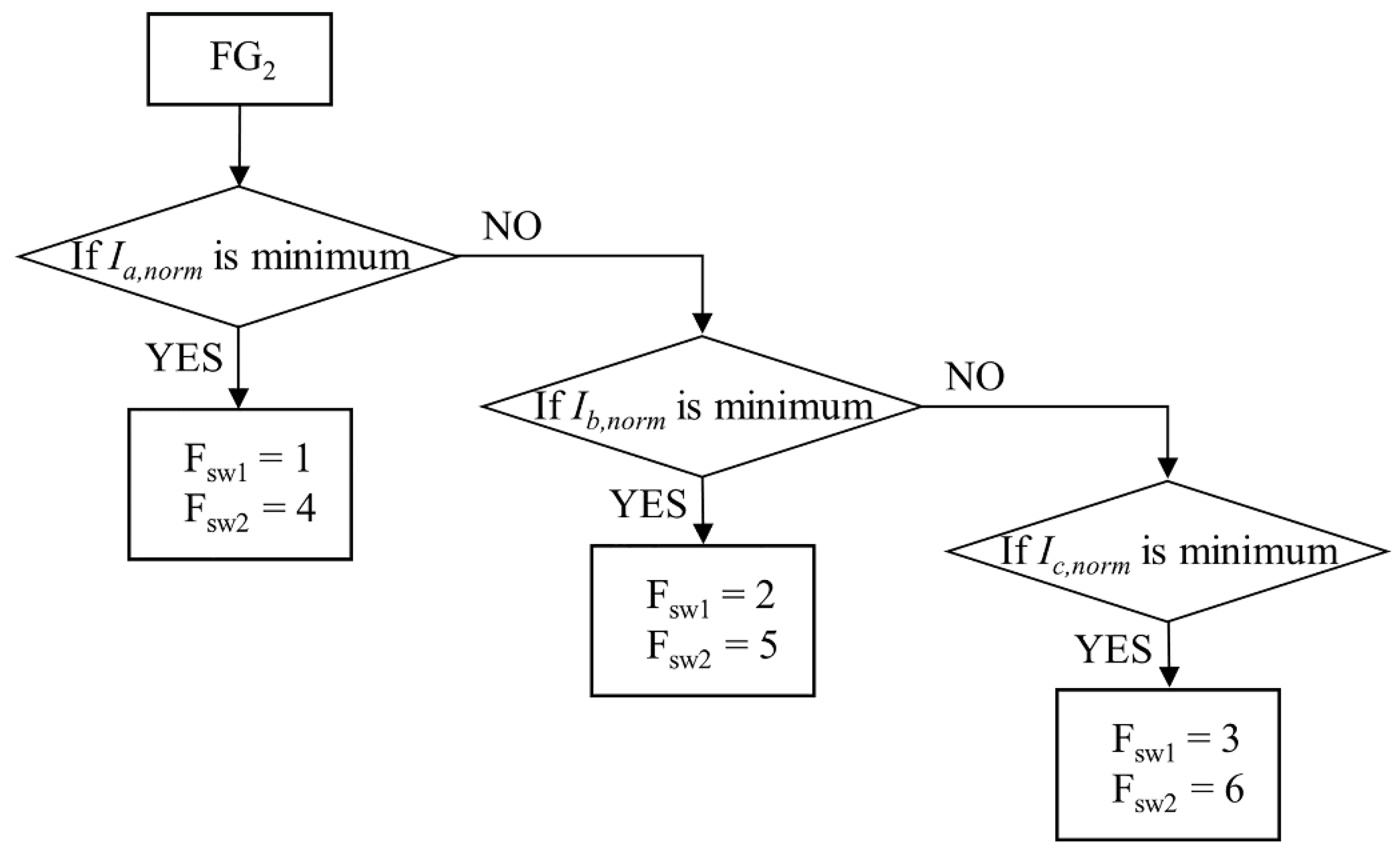
In the fault group FG
2, two faulty switches are effectively detected by finding the phase in which the normalized RMS current
In,norm for
n =
a,
b,
c is minimum. This is due to the fact that one phase current always remains zero in this fault group since the entire switches in one inverter leg have the open-switch faults. For example, under the simultaneous open-switch faults in
S1 and
S4,
Ia,norm remains zero because both the positive and negative
a-phase currents are absent.
Figure 6 shows the detection of two simultaneous faulty switches in FG
2.
In the fault group FG
3, the identification of two faulty switches can be achieved by finding two absent positive and negative currents in three-phase. Because
Nnzc is equal to 4 in this fault group, two absent positive and negative current waveforms provide the information on two faulty switches. For example, under the simultaneous open-switch faults in
S1 and
S5, two absent current waveforms are positive
a-phase current and negative
b-phase current.
Table 3 shows the detection of two simultaneous faulty switches in FG
3, in which
In+ and
In− (for
n =
a,
b,
c) are defined as positive and negative current waveforms in each phase, respectively.
The fault groups FG
4 and FG
5 can be effectively separated from the other remaining groups by using
Nnzc equal to 3. By finding three absent positive and negative currents among three-phase currents, these groups are easily distinguished from other groups. However, all the fault conditions in FG
4 have their counterparts in FG
5 in view of giving exactly the same fault signature in three-phase current waveforms according to the analysis in
Figure 2 and
Table 1.
Table 4 shows the detection of simultaneous faulty switches in FG
4 and FG
5. Under the open faults either in two upper or two lower switches, the fault signature is irrespective of the fault in the opposite switch of the remaining phase, as is observed in the case for the simultaneous open-switch faults in
S1 and
S2 of FG
4, and the simultaneous open-switch faults in
S1,
S2 and
S6 of FG
5 as in
Figure 2. For example, when positive
a-phase, negative
b-phase, and negative
c-phase currents are missing as in the first low of
Table 4, only the simultaneous open-switch faults in
S5 and
S6 are distinct. It is not sure whether the open-switch fault occurs in
S1 or not.
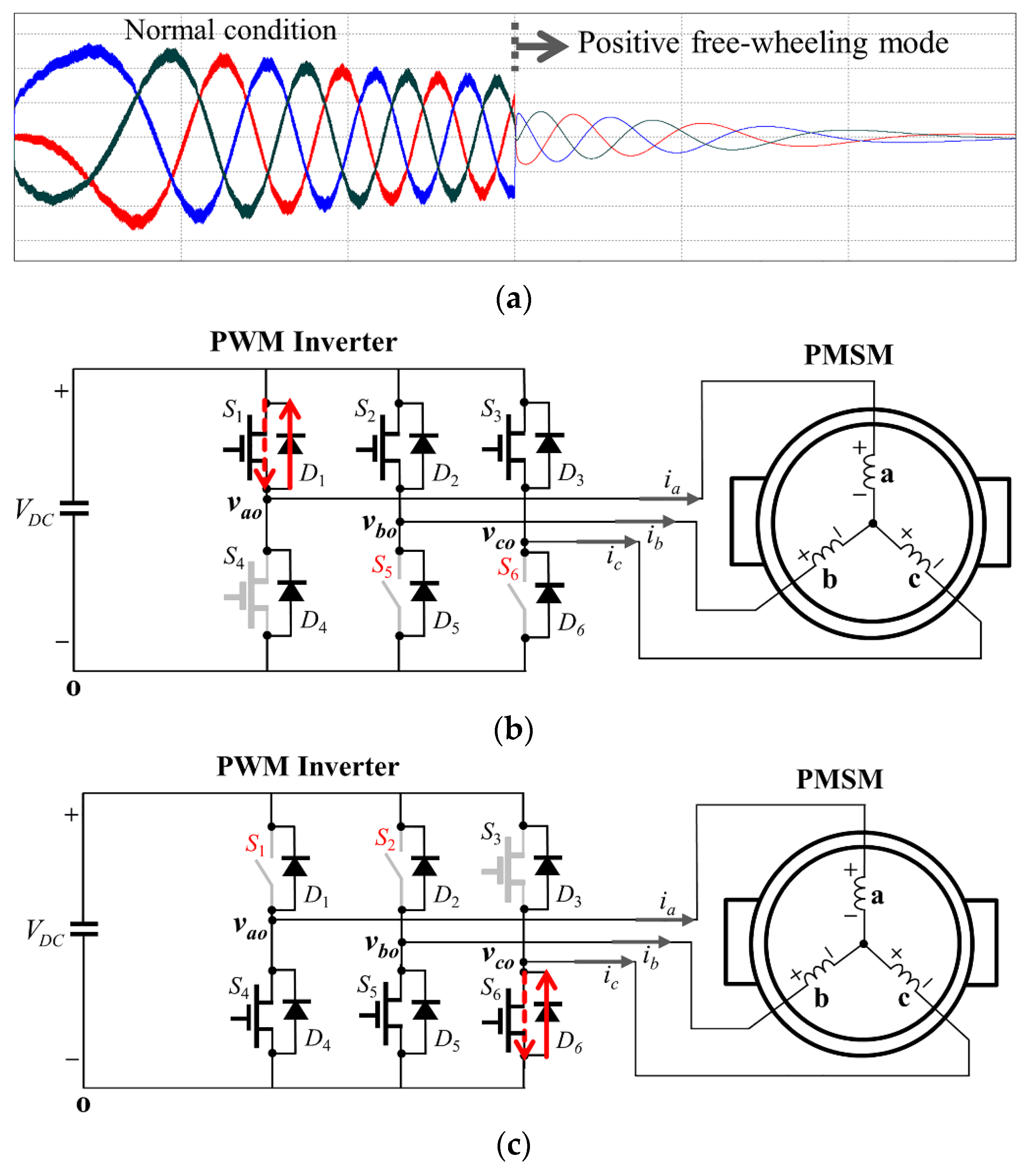
To further distinguish the fault groups FG4 and FG5 as well as to detect all faulty switches, a free-wheeling mode detection is employed, which is composed of the positive free-wheeling mode detection and negative free-wheeling mode detection carried out in sequence. While the inverter upper switches S1, S2 and S3 are forced to turn on to investigate faulty switches during the test period of the positive free-wheeling mode detection, the inverter lower switches S4, S5 and S6 are forced to turn on during that of the negative free-wheeling mode detection. As the free-wheeling mode in inverter decelerates the machine, the free-wheeling mode detection is only applicable to the condition that the machine is rotating with a sufficient speed. In spite of this limitation, it can be a reliable method to detect an open-switch fault for such condition that the faulty switches cannot be clearly detected by using the powering mode.
Figure 7 shows the concept of the free-wheeling mode detection. If the kinetic energy of the machine is sufficient during the free-wheeling mode, the currents flow through the path composed of the switches and diodes, decelerating the machine velocity.
Figure 7a shows three-phase current waveforms during the positive free-wheeling mode under non-fault condition. For the case in the first low of
Table 4, only the simultaneous open-switch faults in
S5 and
S6 are clear and the open-switch fault in
S1 is not sure.
Figure 7b shows the case that the positive free-wheeling mode is applied to detect the open-switch fault in
S1, where the inverter upper switches
S1,
S2 and
S3 are forced to turn on. Whereas negative
a-phase free-wheeling current can flow through diode
D1, positive
a-phase free-wheeling current can flow only when
S1 does not have the open-switch fault. Thus, by investigating the existence of positive
a-phase free-wheeling current, the open-switch fault in
S1 can be determined. As a result, even if both the simultaneous open-switch faults in
S5 and
S6 of FG
4 and those in
S1,
S5 and
S6 of FG
5 develop the same fault signature, the exact fault group and the faulty switch location can be identified by using the positive free-wheeling mode detection.
For the case in the last row of
Table 4, only the simultaneous open-switch faults in
S1 and
S2 are clear and the open-switch fault in
S6 is doubtful.
Figure 7c shows the application of the negative free-wheeling mode to detect the open-switch fault in
S6 for this case, where the inverter lower switches
S4,
S5 and
S6 are forced to turn on. With the negative free-wheeling mode, positive
c-phase free-wheeling current flows through diode
D6. Thus, by investigating the existence of negative
c-phase free-wheeling current, the open-switch fault in
S6 can be determined, which achieves the exact fault localization.
The fault groups FG
6 and FG
7 can be similarly separated with the other remaining groups by using the information on
Nnzc equal to 2, which means that four positive or negative currents among three-phase currents are absent. Similar to the case of the fault groups FG
4 and FG
5, all the fault conditions in FG
6 have their counterparts in FG
7 in view of giving exactly the same fault signature in three-phase current waveforms according to the analysis in
Figure 2 and
Table 1.
Table 5 shows the detection of three simultaneous faulty switches in FG
6 and FG
7. As shown in the first low of
Table 5, when the entire switches of
a-phase inverter leg have open faults, the fault signature is the same irrespective of one additional open-switch either in
S2 or
S6. Thus, when the entire
a-phase, positive
b-phase, and negative
c-phase currents are missing as in the first low of
Table 5, only the simultaneous open-switch faults in
S1 and
S4 are clear. It is not sure where the additional open-switch fault occurs in
S2 or
S6. However, even in this case, the remaining additional open-switch fault can be effectively detected by using the similar way described in
Figure 7. During the positive free-wheeling mode detection, the open-switch fault in
S2 can be determined. If positive
b-phase free-wheeling current exists,
S2 does not have the open-switch fault, and vice versa. Similarly, the open-switch fault in
S6 can be determined during the negative free-wheeling mode detection. If negative
c-phase free-wheeling current exists,
S6 does not have the open-switch fault, and vice versa. As a result, all the fault conditions in the fault groups FG
6 and FG
7 can be effectively identified by the proposed fault localization algorithm.
5. Experimental Results
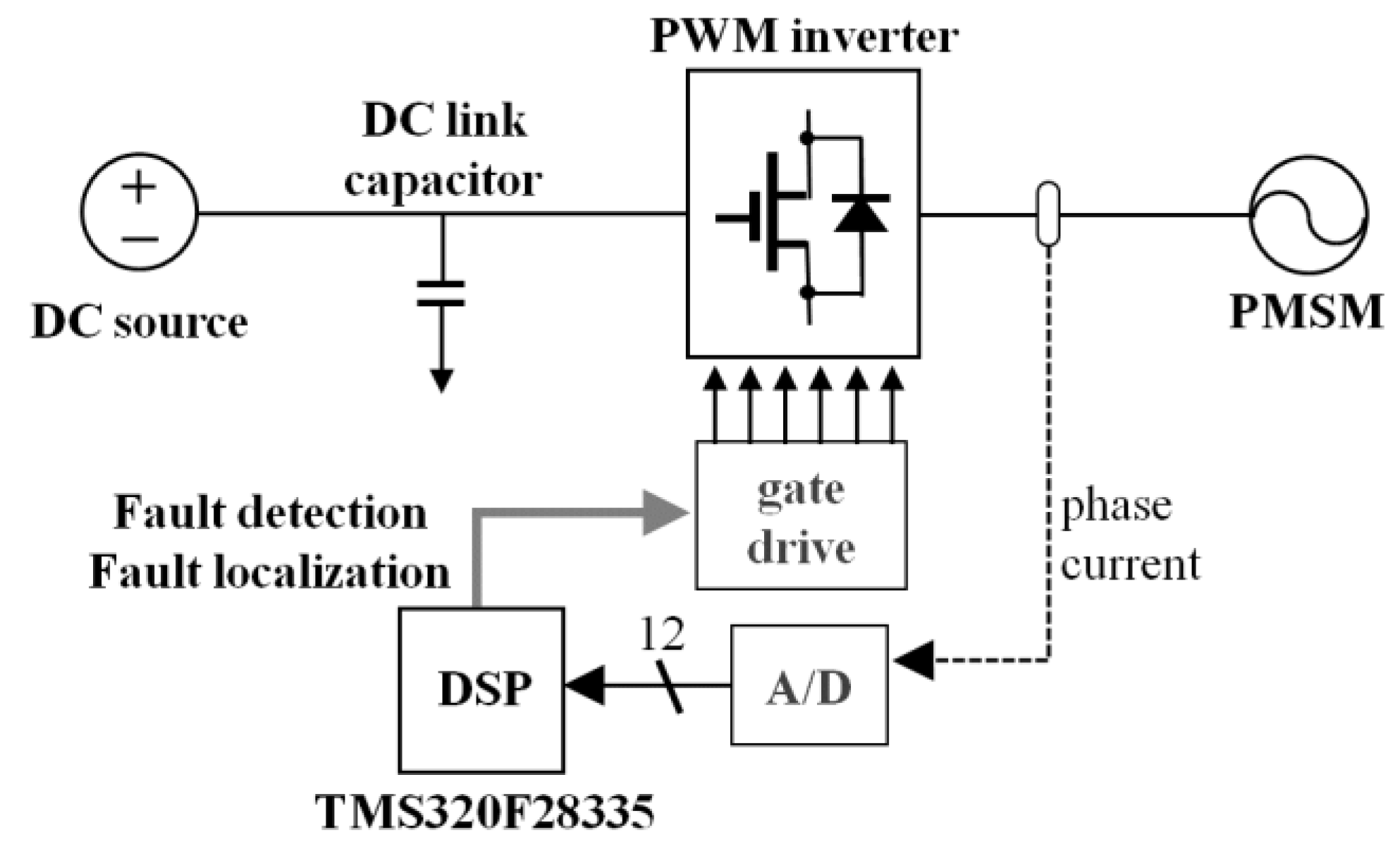
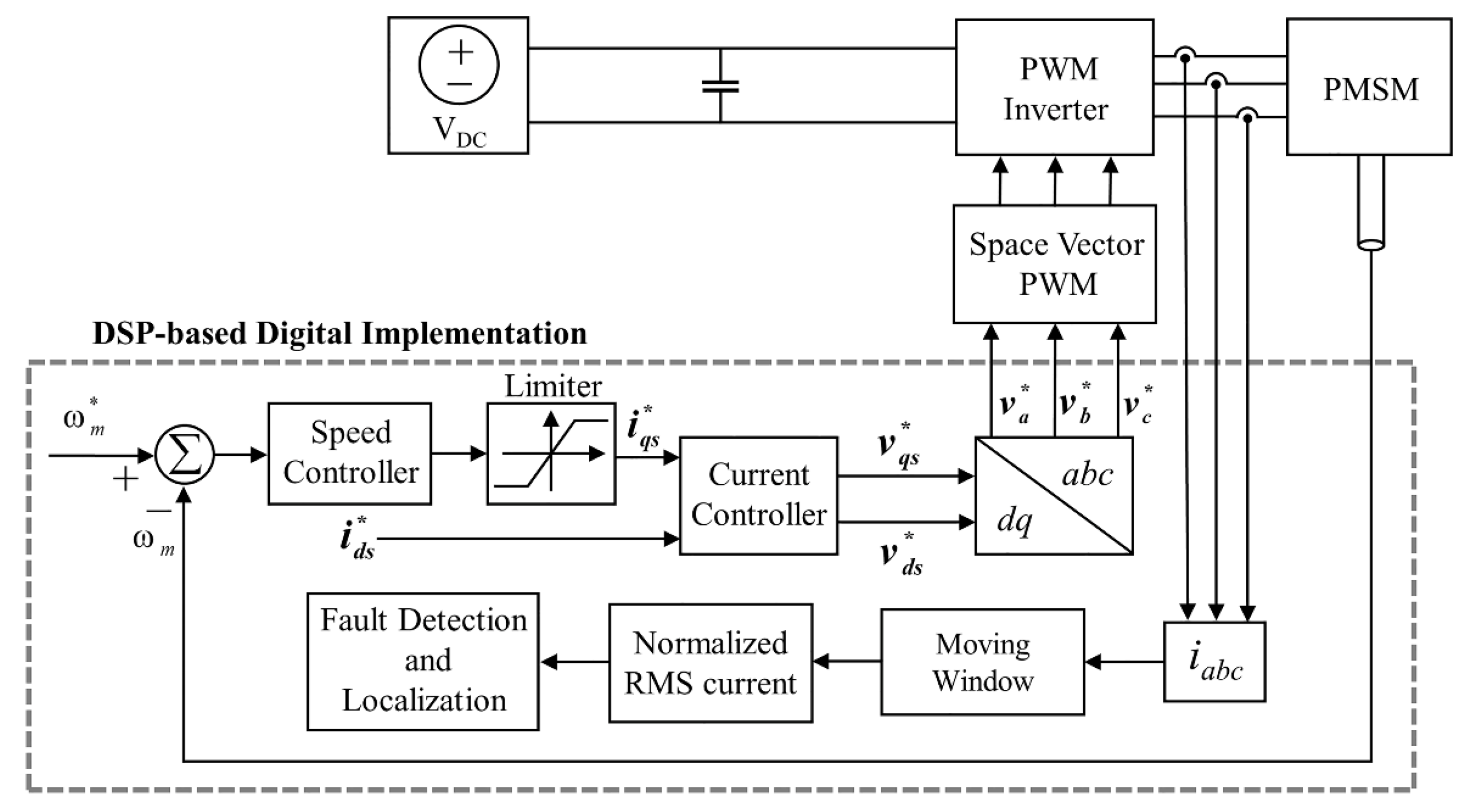
To verify the feasibility and practical usefulness of the proposed on-line fault localization scheme in a PWM inverter-fed PMSM drive system, the experimental results are presented under various open fault conditions. The overall configuration of the experimental system is shown in
Figure 8. The experimental system is composed of a PWM inverter, a PMSM, and a DSP-based digital controller. The entire control and diagnosis algorithm are implemented on TMS320F28335 32-bit floating-point DSP [
37]. Inverter phase currents are measured by the Hall sensors and fed to the DSP using the internal 12-bit A/D converter with the resolution of 40/2
11 A. The sampling period is selected as 100 μs to implement the entire control and diagnosis algorithm. The intelligent power module (IPM) is employed for a PWM inverter and the inverter gate signals are generated through internal 16-bit PWM port in DSP with a switching frequency of 10 kHz.
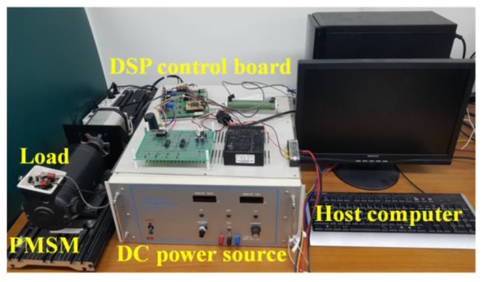
Figure 9 shows a photograph for the experimental test setup consisting of a PMSM, permanent magnet DC (PMDC) generator, and electric load. The specifications and parameters of the PMSM are listed in
Table 6.
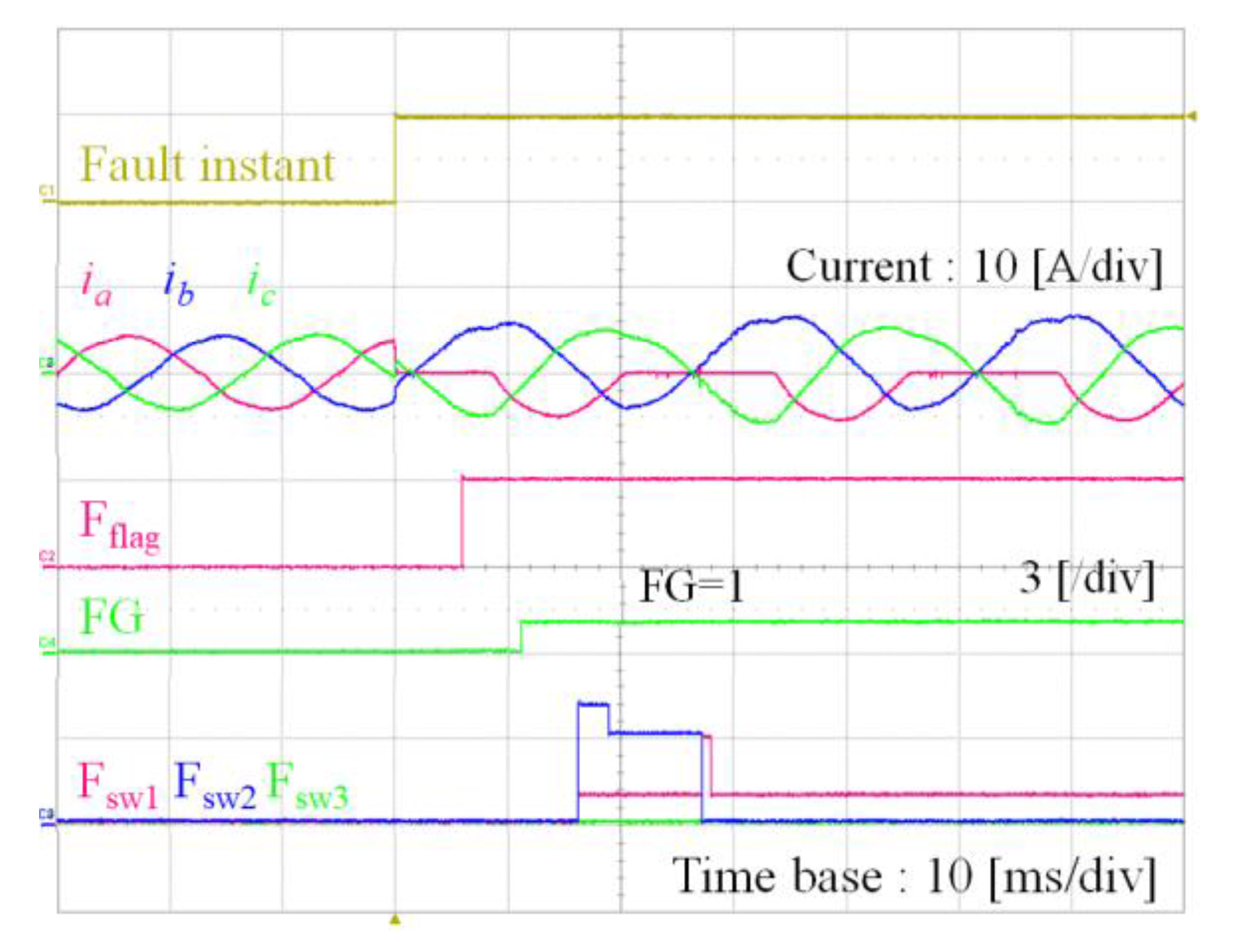
Figure 10 shows the experimental results for the proposed fault detection and faulty switch localization under the open-switch fault in
S1 of FG
1. In this figure, the first waveform indicates the instant of fault occurrence. The second waveforms in
Figure 10 represent three-phase current responses
ia,
ib and
ic. As can be observed, positive
a-phase current does not exist due to the open-switch fault in
S1, which results in
Nnzc equal to 5. As the normalized three-phase RMS currents
In,norm used for a fault detection variable deviate from the nominal value, the fault occurrence is acknowledged instantly by setting the variable F
flag to 1 as shown in the third waveform in
Figure 10. Then, the diagnosis algorithm is changed into the proposed fault localization algorithm to find the fault locations. The first step is to determine the fault group by using the number of positive and negative current waveforms,
Nnzc in
Table 2. The fourth waveform in
Figure 10 shows the detection result for the fault group (FG) which the fault belongs to. The next step is to investigate the faulty switch in FG
1 by using
Figure 5. The last waveforms in
Figure 10 show the values of the faulty switch. In these figures, the values of one through seven are designated to denote the fault group FG
1 through FG
7, and F
sw1, F
sw2, and F
sw3 are employed to denote three faulty switches, respectively. After small transient period, the proposed fault localization scheme determines FG = 1, F
sw1 = 1, F
sw2 = 0, and F
sw3 = 0, which indicates that the fault belongs to FG
1 and the open-switch fault location is
S1.
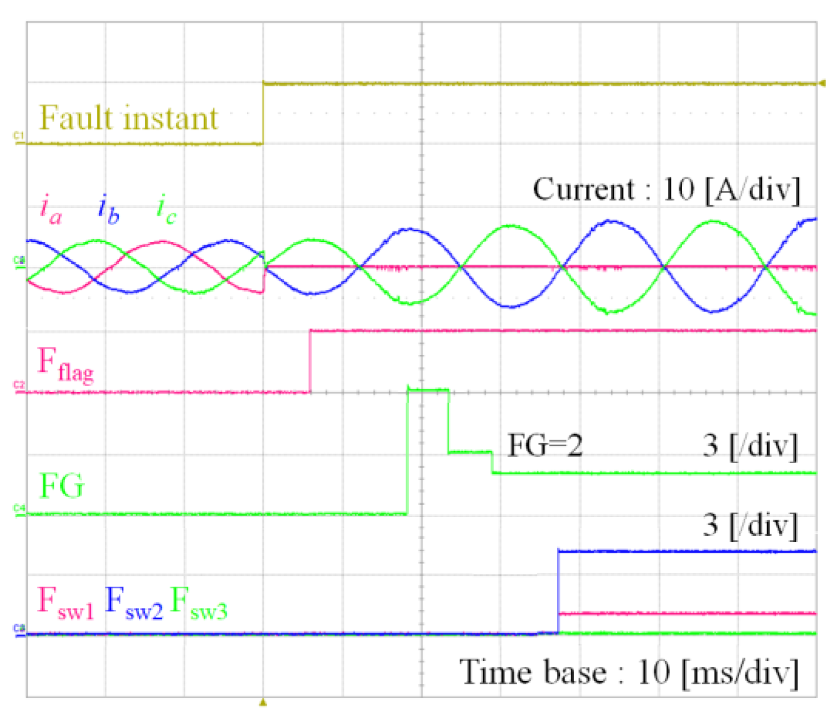
Figure 11 shows the experimental results for the proposed fault detection and faulty switch localization under the simultaneous open-switch faults in
S1 and
S4 of FG
2. Similarly, the waveforms represent the instant of fault occurrence, three-phase currents responses, the variable F
flag, the detected result for FG, and three faulty switches F
sw1, F
sw2 and F
sw3 respectively, from the top. As can be observed in three-phase currents, entire
a-phase current
ia is very close to zero due to the open-switch faults in
S1 and
S4. As soon as the detection variable,
Ia,norm deviates from the nominal value, the fault occurrence is acknowledged. In addition, the fault group is determined as FG
2 by using
Nnzc = 4 and
Ia,norm = 0 in
Table 2. Then, the proposed fault diagnosis algorithm investigates the faulty switches by using
Figure 6. The final detection results are FG = 2, F
sw1 = 1, F
sw2 = 4, and F
sw3 = 0, which indicates that the fault belongs to FG
2 and the open-switch faults occur in
S1 and
S4 as shown in
Figure 11.
Figure 12 shows the experimental results for the proposed fault detection and faulty switch localization under the simultaneous open-switch faults in
S1 and
S5 of FG
3. As is obvious in three-phase currents,
a-phase positive current and
b-phase negative current do not exist, which yields
Nnzc = 4. Following the procedures in
Table 2 and
Table 3, the proposed fault diagnosis algorithm determines FG = 3, F
sw1 = 1, F
sw2 = 5, and F
sw3 = 0 as the final detection results, which indicates that the fault belongs to FG
3 and the open-switch faults occur in
S1 and
S5 as shown in
Figure 12.
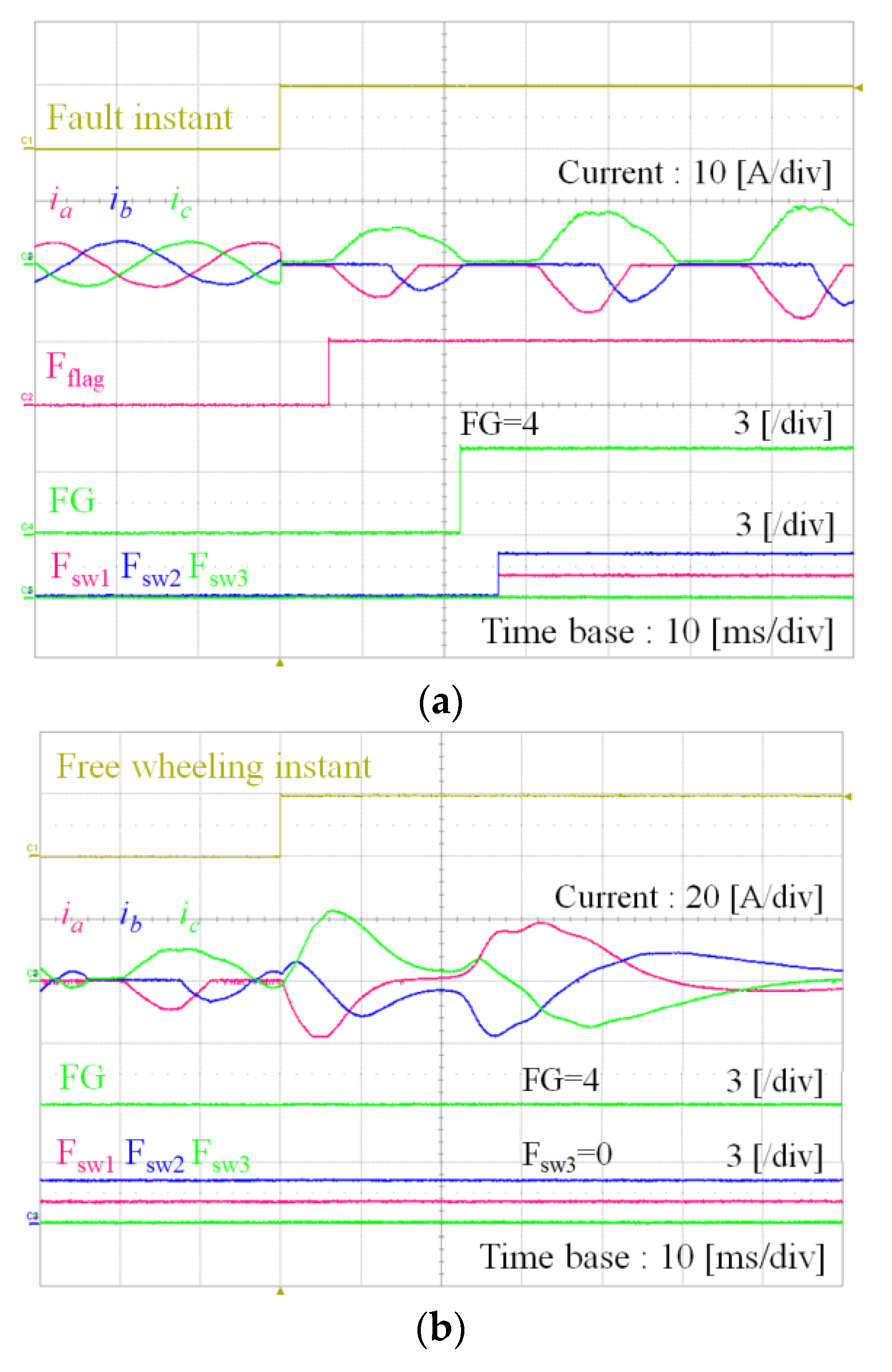
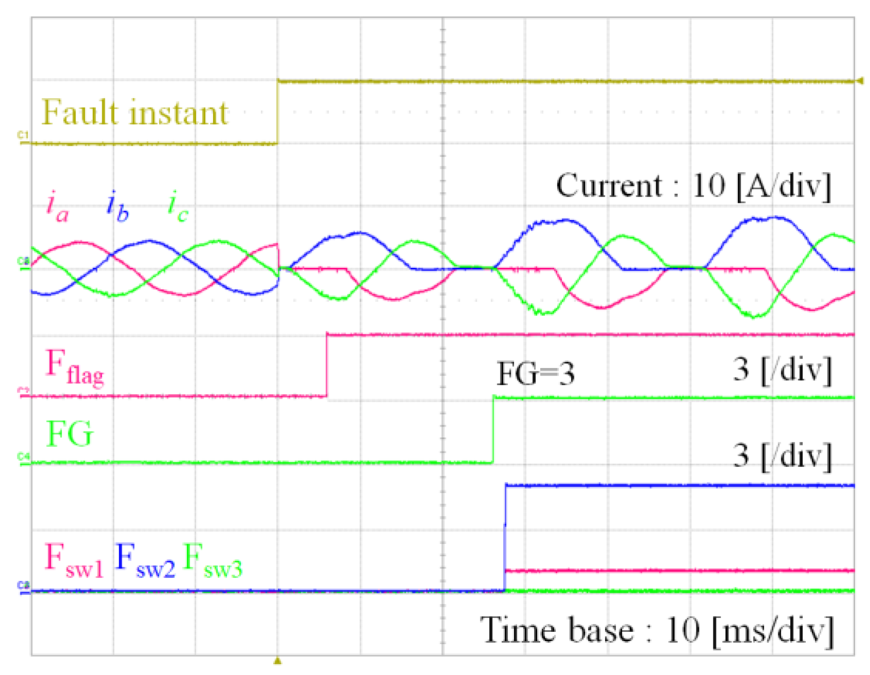
Figure 13 shows the experimental results for the proposed fault detection and faulty switch localization under the simultaneous open-switch faults in
S1 and
S2 of FG
4. In this fault condition, the number of positive and negative current waveforms,
Nnzc is equal to 3 because only
a-phase negative,
b-phase negative, and
c-phase positive currents exist as shown in
Figure 13a. Following the procedures in
Table 2, the fault group is determined as FG
4 or FG
5. Also, according to
Table 4, the simultaneous open-switch faults in
S1 and
S2 are clear and the additional open-switch fault in
S6 is not sure. To detect the remaining additional open-switch fault, the detection by free-wheeling mode test is introduced by using the method described in
Figure 7 as shown in
Figure 13b. In this case, since the possible location for open-switch is the inverter lower side, the negative free-wheeling mode detection is employed. When the negative free-wheeling mode is applied, the open-switch fault in
S6 can be detected by investigating negative
c-phase free-wheeling current as shown in
Figure 7b. It is shown from
Figure 13b that all the positive and negative free-wheeling currents exist. Thus, it can be concluded that the switch
S6 does not have the open-switch fault. As a result, the proposed fault diagnosis algorithm determines FG = 4, F
sw1 = 1, F
sw2 = 2, and F
sw3 = 0 as the final detection results, which indicates that the fault belongs to FG
4 and the open-switch faults occur in
S1 and
S2 as shown in
Figure 13.
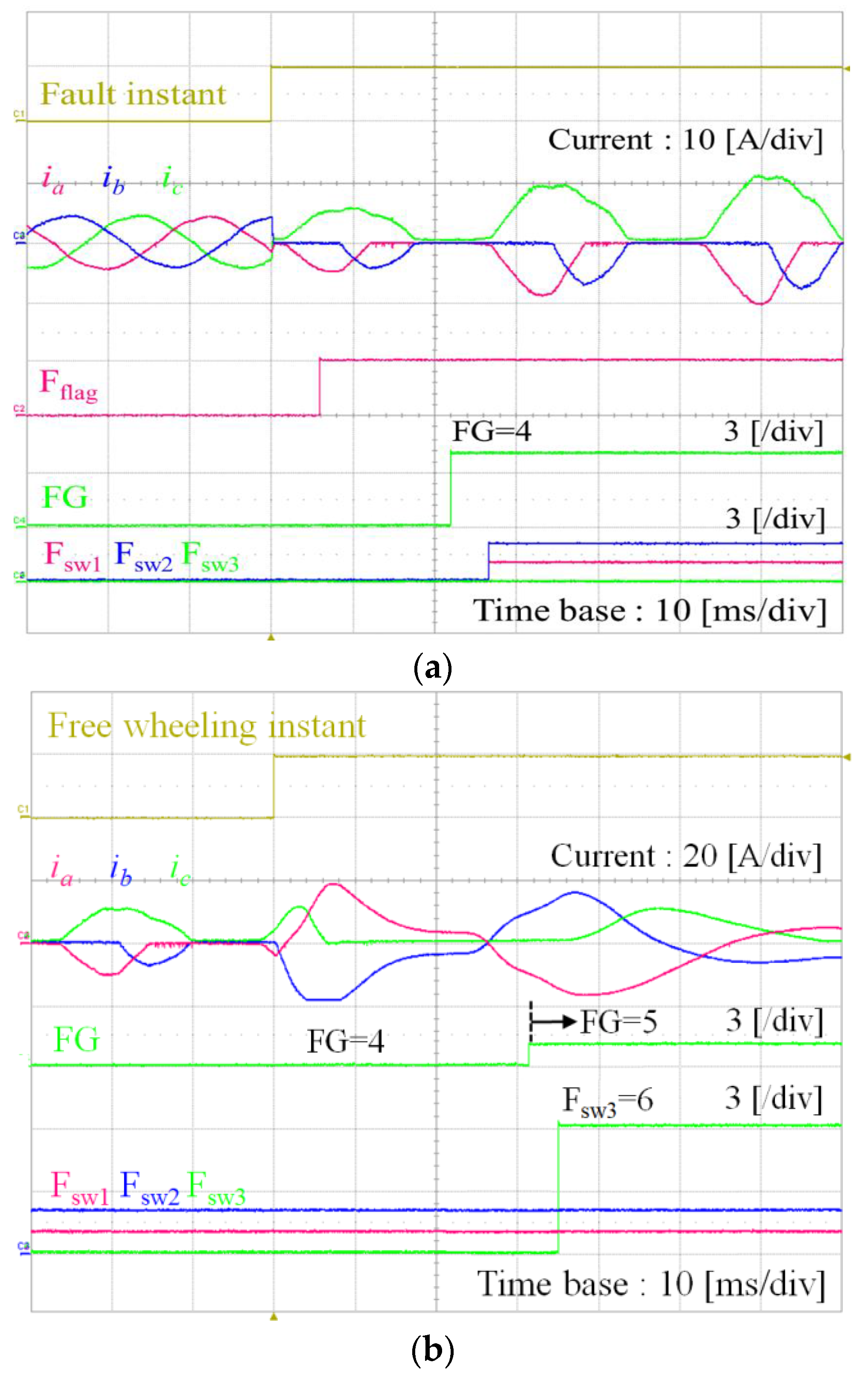
Figure 14 shows the experimental results for the proposed fault detection and faulty switch localization under the simultaneous open-switch faults in
S1,
S2 and
S6 of FG
5. As shown in the current waveforms in
Figure 13a and
Figure 14a, this fault condition gives the same fault signature with that of the open-switch faults only in
S1 and
S2. Following the procedures in
Table 2, the fault group is determined as FG
4 or FG
5, and the simultaneous open-switch faults in
S1 and
S2 are only clear and the additional open-switch fault in
S6 is not sure according to
Table 4. Similarly, the remaining additional open-switch fault can be effectively detected by negative free-wheeling mode test as shown in
Figure 14b. It is clearly shown in
Figure 14b that
c-phase negative current does not exist during the negative free-wheeling mode test, even though other phases have both positive and negative currents, which implies the open-switch fault in
S6. Thus, the final detection results of the proposed fault diagnosis algorithm are FG = 5, F
sw1 = 1, F
sw2 = 2, and F
sw3 = 6, which indicates that the fault belongs to FG
5 and the open-switch faults occur in
S1,
S2 and
S6 as shown in
Figure 14b.
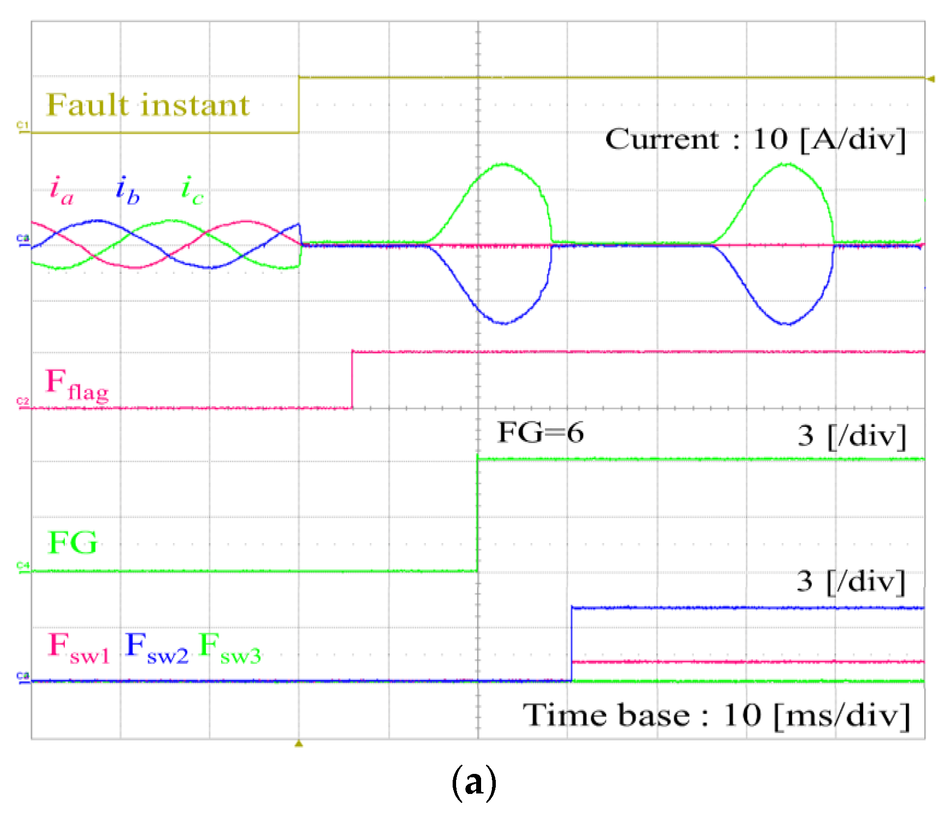
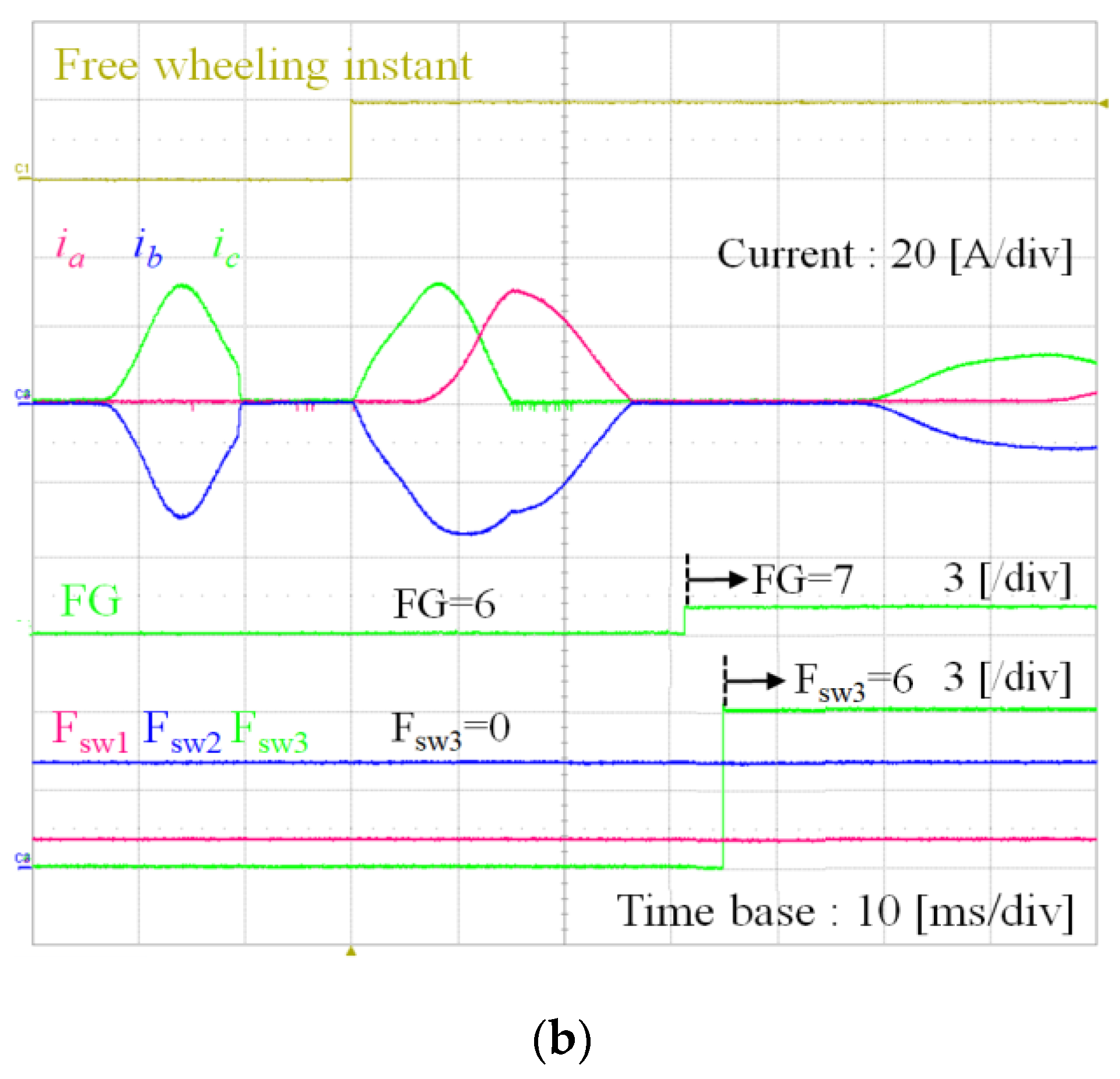
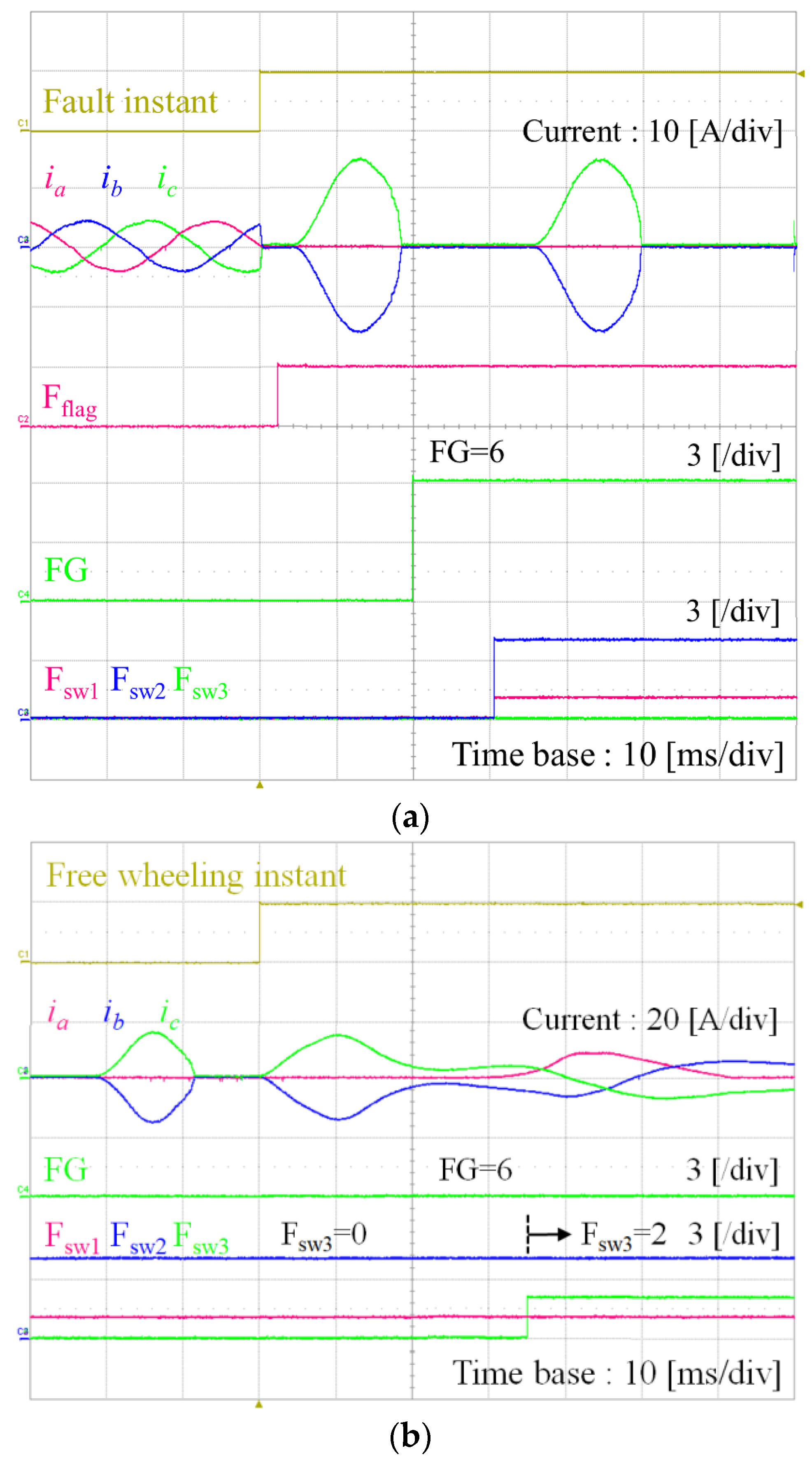
Figure 15 and
Figure 16 show the experimental results for the proposed fault detection and faulty switch localization under the simultaneous open-switch faults in
S1,
S2 and
S4 of FG
6, and under the simultaneous open-switch faults in
S1,
S4 and
S6 of FG
7, respectively. As explained in
Table 1, these two fault conditions give the same fault signature in current waveforms as shown in
Figure 15a and
Figure 16a. Because only two positive or negative currents exist,
Nnzc is equal to 2. Following the procedures in
Table 2, these fault groups FG
6 or FG
7 can be separated with the other remaining groups. Thus, the simultaneous open-switch faults in
S1 and
S4 are only clear and the additional open-switch fault either in
S2 or in
S6 is not sure according to
Table 5.
To investigate the remaining additional open-switch fault, the negative free-wheeling mode test is employed as shown in
Figure 15b and
Figure 16b. Whereas
c-phase negative current exists in
Figure 15b during the negative free-wheeling mode test, it does not exist in
Figure 16b. Thus, in addition to the simultaneous open-switch faults in
S1 and
S4, the remaining additional open-switch can be detected as
S2 in
Figure 15 and as
S6 in
Figure 16. As a result, the final detection results in the condition of
Figure 15 are FG = 6, F
sw1 = 1, F
sw2 = 4, and F
sw3 = 2, which indicates that the fault belongs to FG
6 and the open-switch faults occur in
S1,
S4 and
S2 as shown in
Figure 15b. On the other hand, the final detection results in the condition of
Figure 16 are FG = 7, F
sw1 = 1, F
sw2 = 4, and F
sw3 = 6 as shown in
Figure 16b.
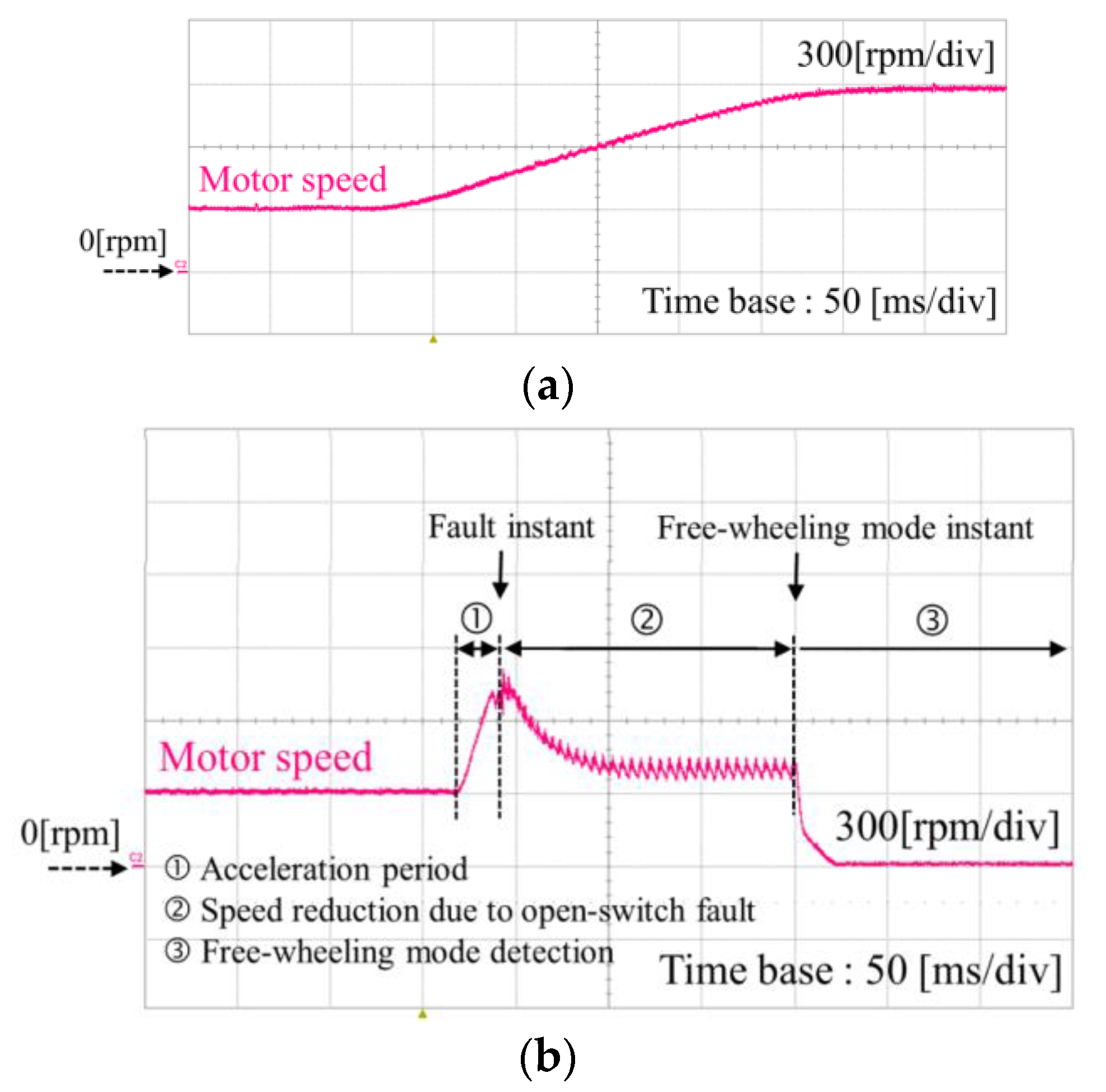
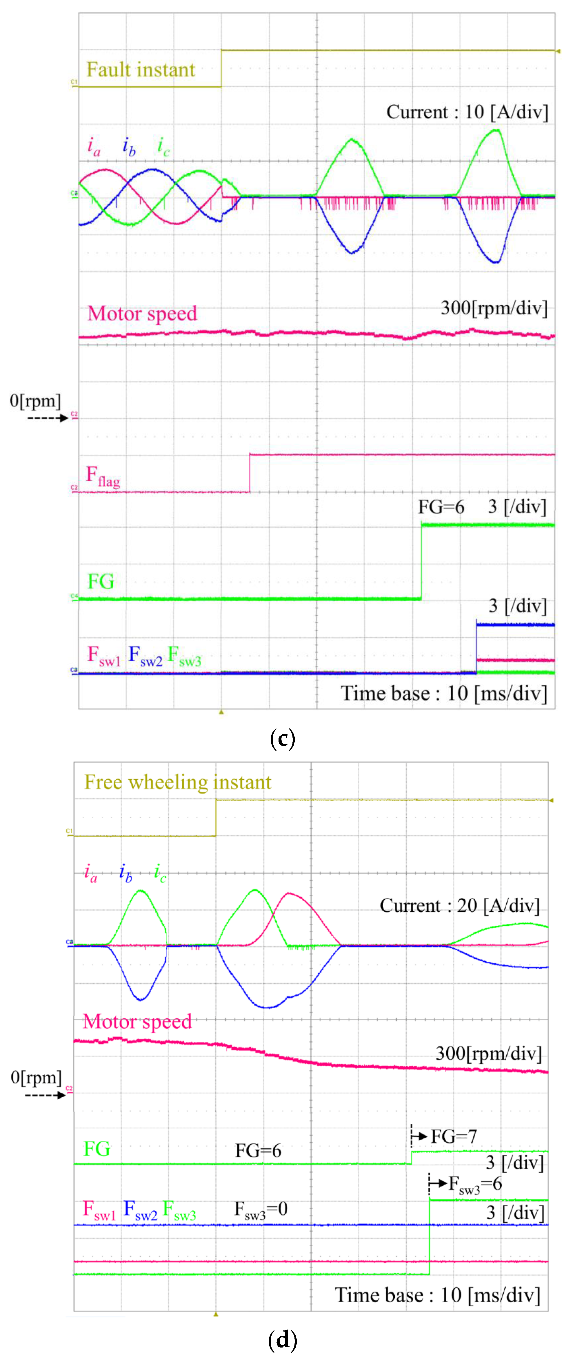
Figure 17 shows the experimental results for the proposed fault detection and faulty switch localization during acceleration period under the same simultaneous open-switch faults with
Figure 16.
Figure 17a shows the speed profile during acceleration period and
Figure 17b shows the motor speed variation during the entire operation of detection algorithm including acceleration period. Even when the speed is increasing, the fault occurrence can be effectively detected as shown in
Figure 17c.
Section 4, it can clearly detect both the fault group and faulty switches as shown in
Figure 17d. Through the experiments under various fault conditions, it has been clearly demonstrated that the proposed fault diagnosis scheme works effectively and reliably, even when the inverter has simultaneous open faults in three multiple switches. It is confirmed from the experimental results that the proposed diagnosis scheme works well in a practical drive system with a sufficient accuracy and rapidness.


