Small-Signal Performance of Type 4 Wind Turbine Generator-Based Clusters in Power Systems


1
School of Electrical and Information Engineering, The Jiangsu University, Zhenjiang 212013, China
2
School of Science and Engineering, The Chinese University of Hong Kong, Shenzhen 518100, China
3
School of Electrical and Information Engineering, The University of Sydney, Sydney, NSW 2006, Australia
*
Authors to whom correspondence should be addressed.
Energies 2018, 11(6), 1486; https://doi.org/10.3390/en11061486
Submission received: 28 April 2018
/
Revised: 3 June 2018
/
Accepted: 4 June 2018
/
Published: 7 June 2018
Abstract
:The impact of Type 4 wind turbine generator (WTG)-based 10 million megawatt clusters (TMMC) on small-signal dynamics of power systems was investigated using the second-generation generic models (GM) of Western Electricity Coordinating Council (WECC). A WTG participation index (WTG PI) was defined to investigate the impact of Type 4 WTGs on the traditional interarea electromechanical modes. To identify the new electromechanical modes dominated by Type 4 WTGs, an identification factor (IF) was also defined using participation factors. Given the increasing penetration of Type 4 WTGs replacing synchronous generators, the changed law of damping and frequencies of the traditional interarea modes was also investigated using the WTG PI. One new type of electromechanical mode dominated by Type 4 WTGs was identified by using the defined IF. These new modes can be divided into two categories: strong-interaction modes and weak-interaction modes, depending on the number of participating WTGs. The strong-interaction modes dominated by Type 4 WTGs can result in widely spread power oscillations in power systems. The results of small-signal analysis were validated by time domain simulation and mode detection.
1. Introduction
The Type 4 wind turbine generator (WTG)-based 10 million megawatt cluster (TMMC) has been put into operation in the northwest China Grid. The Type 4 WTG-based TMMC consist of dozens of wind farms that are centrally integrated into one area of a power system. Its total capacity is greater than 10 million megawatts. The capacity of Type 4 WTGs is increasing recently, and they account for more than one-third of the total capacity of wind turbine generators in China. However, Type 4 WTGs are connected to power systems using electronic converters. This is different from the traditional synchronous generators that are directly connected to power systems. The mechanical dynamics of Type 4 WTGs are completely decoupled from power systems. Thus, they cannot provide inertia response for the connected power systems, which may cause the dynamic damping of the connected power systems to become so weak that it is difficult to damp out the power oscillation during small-signal events. In other words, Type 4 WTG-based TMMCs have a significant impact on the electromechanical dynamic performance of power systems. Industrial circles have shown concerns about the impact of Type 4 WTG-based TMMCs on small-signal performance of power systems in China. Therefore, it is urgent to investigate the impact of Type 4 WTG-based TMMCs on small-signal performance of power systems.
Using a single machine infinite bus system, some works addressed the modal characteristics of Type 4 WTGs themselves [1,2,3], but they did not investigate the impact of Type 4 wind turbine generators on the small-signal stability of power systems by using a multimachine power system. The supplementary frequency and oscillation control loops of Type 4 WTGs have been presented for emulating inertia response by using a single machine infinite bus system as well [4,5,6]. In terms of the small-signal stability for multimachine power systems, a previous study focused on the impact of Type 3 WTGs on small-signal stability of power systems. However, compared with Type 3 WTGs, Type 4 WTGs have a different impact on the small-signal stability of power systems. The previous conclusions for Type 3 WTGs are not applicable for Type 4 WTGs. A thorough survey of literature shows that the potential impact of Type 4 WTG-based TMMCs on the electromechanical behavior of power systems has received little study.
The impact of the combination of Type 3 WTGs, Type 4 WTGs and utility-scale photovoltaic systems on the small-signal stability of power systems has been investigated by using the first-generation generic models (GMs) of Western Electricity Coordinating Council (WECC) and General Electric models in production-level power systems [7]. Most previous studies adopted custom models [1,2,3] or the first-generation GMs of WTGs for analysis of small-signal stability [7]. They were hardly validated by measured data. Additionally, the active power control seemed to be too simple for the first-generation Type 4 GM; the reactive power control of the first-generation GM does not cater to various reactive power injection options of various designs [8]. These above defects of the first-generation Type 4 GM can result in the incorrect results.
The WECC developed the second-generation GMs for representing wind farms after the first-generation GMs had been implemented for several years [8,9,10,11,12,13,14,15]. The second-generation GMs improved the above limitations of the first-generation GMs. Also, the second-generation GMs have been verified through a large number of field-measured data. As such, the second-generation GMs can reliably describe the electromechanical dynamics of WTGs from different manufacturers. No literature has been found with regard to adopting the second-generation GMs to study the influence of Type 4 WTGs on the small-signal stability of power systems.
Despite that the commercial software of power system simulation PSS/E [16] was used to conduct the analysis, the contributions of this work are:
(1) The identification of two undocumented types of electromechanical modes dominated by Type 4 WTGs: strong-interaction modes and weak-interaction modes.
Almost all Type 4 WTGs connected to power systems participate in the strong-interaction modes; with the increase of wind penetration levels, their damping gradually becomes weak, and finally negative. The strong-interaction modes can result in widely spread power oscillations in power systems. However, the weak-interaction modes are only related to a few WTGs, and the damping of weak-interaction modes is almost constant with the increase of wind generation penetration. Therefore, the strong-interaction modes of Type 4 WTGs have a significant impact on the security of power systems, but this is not the case for the weak-interaction modes.
(2) The second-generation GMs of Type 4 WTGs were used to implement a simulation analysis in a moderate-scale test bed of the IEEE 16-machine 68-bus standard test system. Each wind farm in the TMMC was represented by a Type 4 equivalent WTG using the second-generation GM. The impact of Type 4 WTG-based TMMC on the small-signal performance of power systems was firstly investigated in this work using the second-generation GM.
The rest of the paper is organized as follows. Section 2 presents the fundamental basis of the modal-based small-signal stability analysis used in this work. Section 3 presents the framework of the second-generation of Type 4 WTGs. With the increasing penetration level of Type 4 WTGs, two new kinds of modes dominated by Type 4 WTGs are identified and characterized in Section 4. Finally, the conclusions are summarized in Section 5.
2. Theory of Small-Signal Stability Analysis with WTGs
2.1. Small-Signal Stability Theory
Similar to the conventional power systems, the electromechanical dynamics of power systems involving WTGs can be also described as differential algebraic equations. Nonlinear first-order ordinary differential equations are used to describe the dynamic characteristics of the components concerned. The quasi-steady-state behavior of a transmission network is represented by nonlinear algebraic equations [7]. Assuming the steady-state equilibrium point of the system is not a singularity of network equations, these differential algebraic equations can be linearized as a standard formulation:
where A is the Jacobian matrix of the linearization equation of differential algebraic equations.
According to the Lyapunov stability theory, the sign of the eigenvalues of the Jacobian matrix determines the stability of the linearized system. Traditional synchronous generators (SG) are directly connected to the alternative current (AC) power network. The rotor flux is directly fixed to the rotor. When the rotor is disturbed, the rotor flux linkage changes with the actual physical position of the rotor, so that the generator rotor oscillates to induce power oscillation and synchronization stability issues. The traditional power oscillation modes of power systems only involve electromechanical modes governed by synchronous generators. Therefore, the previous study of the power oscillation of power systems only focused on traditional electromechanical modes governed by SGs. A traditional electromechanical mode corresponds to a pair of complex eigenvalues, . Its damping ratio is defined as .
The eigenvalues satisfy
where is the nth column of the right eigenvector matrix, u of A; is the nth row of the left eigenvector matrix, v of A; they are respectively called the right and left eigenvectors. The relationship between the right and the left eigenvectors can be expressed as v = u−1.
The normalized right eigenvector ui and the left eigenvector vi are combined to form the participation matrix p, which is used to measure the degree of correlations between modes and state variables. The kth row ith column of elements of the participating matrix p can be expressed as,
where pki is called the participation factor. The participation factor is dimensionless and used to measure the degree of mutual involvement between the ith mode and the kth state variable.
2.2. Impact of Type 4 WTGs on Traditional Electromechanical Modes
For n synchronous generators in power systems, there are usually (n − 1) electromechanical modes. In order to assess the impact of Type 4 WTGs on traditional interarea electromechanical modes, the participation of Type 4 WTGs in traditional interarea electromechanical mode i can be determined through a WTG participation index (PI):
where denotes the summation of participation factors of all state variables of the system affecting mode i; denotes the sum of participation factors of the state variables of WTGs affecting mode i; greater than 0.1 is used to calculate and smaller than 0.1 is negligible.
If , the Type 4 WTGs in the TMMC have no participation in traditional interarea electromechanical modes. If not, the Type 4 WTGs have an impact on traditional interarea electromechanical modes.
2.3. Identification of Electromechanical Modes Dominated by Type 4 WTGs
The rotor oscillations of permanent magnet synchronous generators (PMSG) will result in the power oscillation and synchronization stability issues when they are directly connected to AC networks. However, the PMSGs of Type 4 WTGs are integrated into power systems using electronic converters. Previously, it was believed that mechanical dynamics of Type 4 WTGs are completely decoupled from the power grid so that Type 4 WTGs’ electromechanical oscillations cannot spread into the connected power system. However, this paper draws the conclusion that the electromechanical oscillations of PMSGs of Type 4 WTGs may spread into the connected power system.
The electromechanical modes of Type 4 WTGs should be strongly related to the mechanical state variables of the drive-train model, wtgt_a, such as ωt, ωg, δt and δg. However, a large number of oscillation modes can be solved by Equation (3), but only a few of them are dominated by the PMSGs of Type 4 WTGs. To identify the electromechanical modes dominated by Type 4 WTGs, the identification factor (IF) of the mechanical state variables of Type 4 WTGs in mode i, λi, is defined using participation factors:
where denotes the sum of participation factors of the mechanical state variables (ωt, ωg, δt and δg) of WTGs affecting mode i.
In general, if , the corresponding mode is the electromechanical mode dominated by Type 4 WTGs; on the contrary, if IFi << 1, it is a non-electromechanical mode. The performance of the new electromechanical modes participating in power oscillations can be verified by time-domain simulation and signal detection.
3. Second-Generation Generic Models of Type 4 WTGs
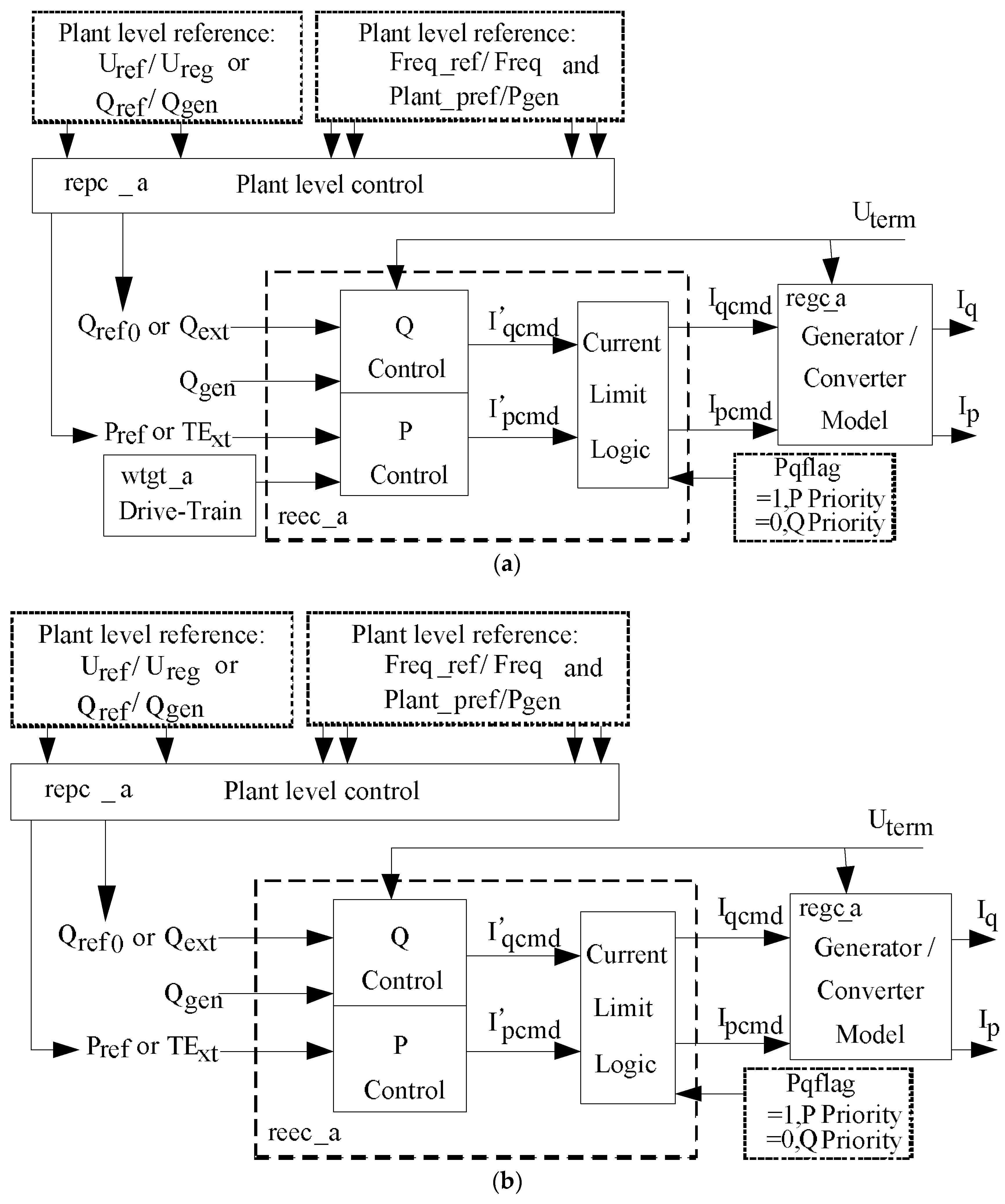
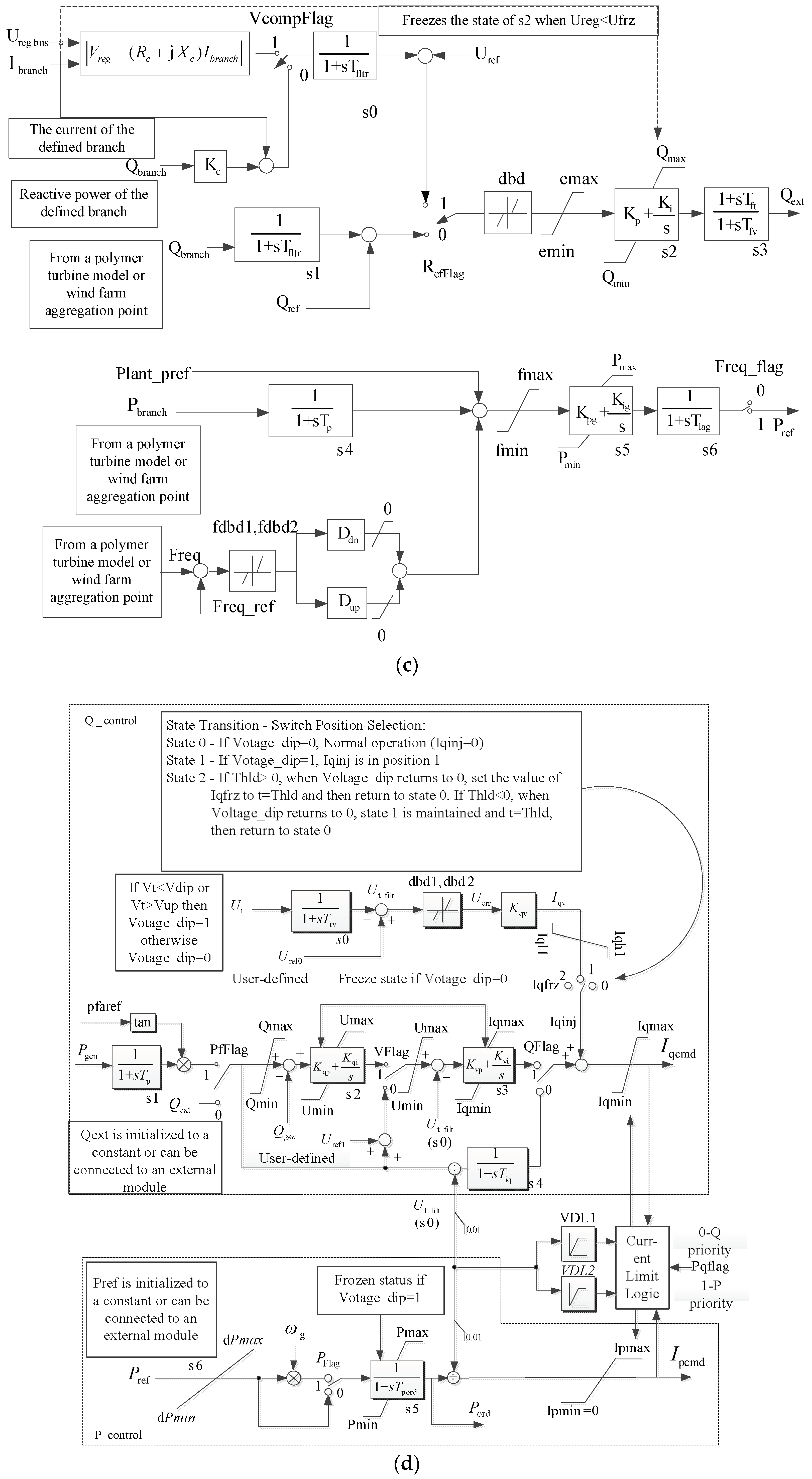
During 2009–2014, due to the need for generic, standard and publicly available models for variable generation technologies, WECC developed second-generation GMs for representing wind farms/WTGs. The second-generation GMs have improved the defects of first-generation GMs by controlling the structure, function, portability and other aspects. The second-generation GMs were validated through a large number of field data. This shows that the second-generation GMs can reliably describe the electromechanical time-scale dynamics of wind farms/WTGs in large-scale power systems. The submodels—repc_a, reec_a, regc_a and wtgt_a—are illustrated in c–f of Figure 1, respectively. Ipcmd and Iqcmd are the active and reactive current commands; Uterm is the generator terminal voltage; Uref/Ureg is the optional remote control bus voltage.
The second-generation GMs of Type 4 WTGs are divided into Type 4A and Type 4B models [8,9,10,11,12,13,14,15], as shown in Figure 1a,b. The Type 4A model consists of the generator/converter model (regc_a), electrical control model (reec_a), shaft model (wtgt_a) and plant-level controller model (repc_a). The Type 4B model includes all components, except for the shaft model (wtgt_a). When power grid faults occur, if the electromagnetic power output of the WTG involves a significant torsional oscillation, it is appropriate to use the Type 4A model; if not, then the Type 4B model is used. The Type 4A model preserves the influence of the electromechanical modes of PMSGs, while the Type 4B model neglects the influence of the electromechanical modes of PMSGs. In this study, the Type 4A model was used to study the effect of electromechanical oscillation modes of Type 4 WTGs. The details of Type 4A models can be found in [8].
The flag RefFlag is set in repc_a. The voltage control is implemented when RefFlag = 1, while the constant reactive power control is realized when RefFlag = 0.
The input of reec_a is derived from the active power reference Pref and the reactive power reference Qext, both of which are obtained by the repc_a. The output of reec_a is the active current command (Ipcmd) and the reactive current command (Iqcmd), which transfer to the repc_a. The internal part of reec_a consists of three parts: active power control (generates the command Ipcmd), reactive power control (generates the command Iqcmd) and converter current limit logic, which limits the active and reactive currents to the current rating of the converter inside.
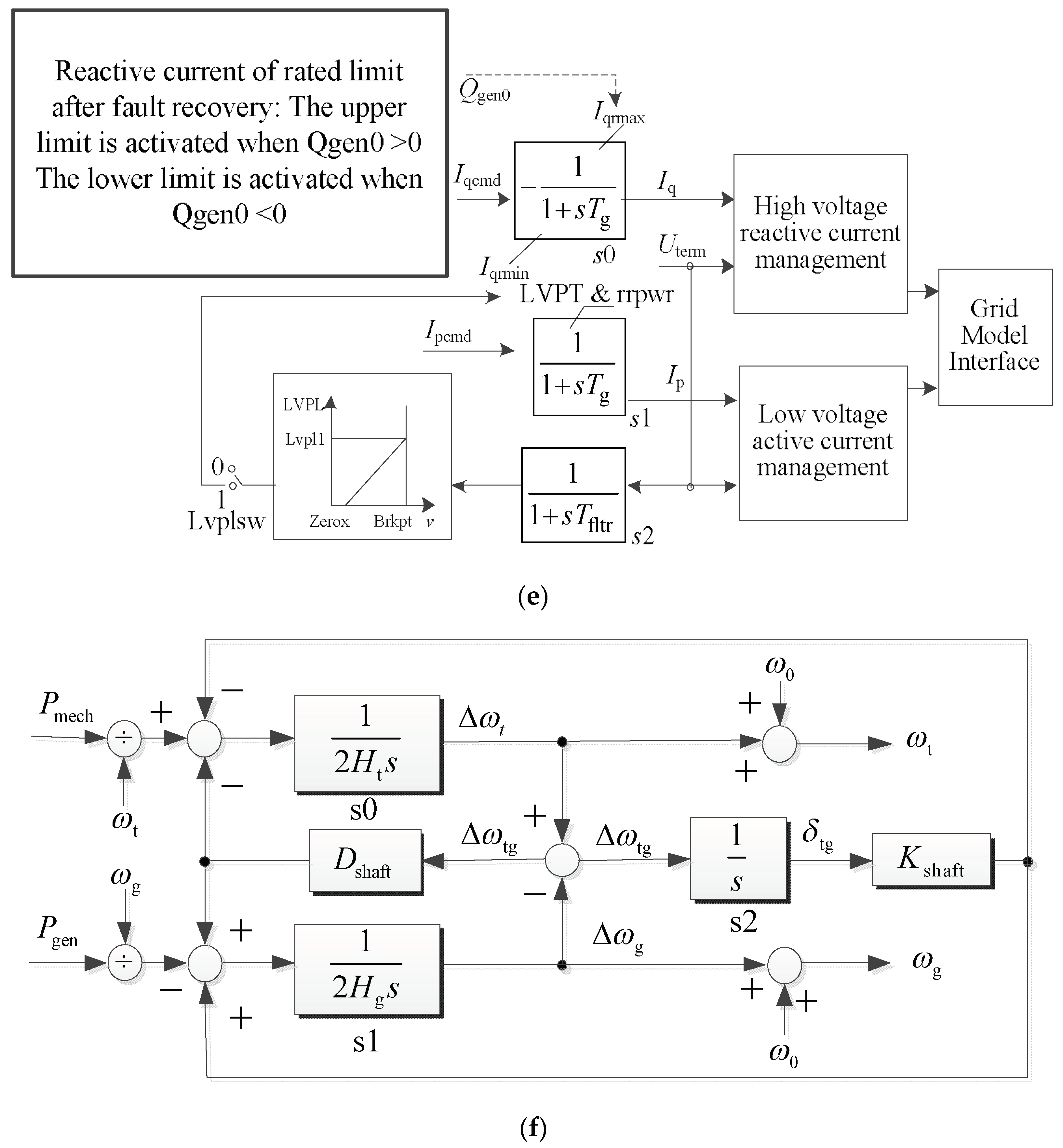
The active current command Ipcmd and the reactive current command Iqcmd are the inputs of regc_a. The outputs of the model are the active current Ip and reactive current Iq injected into the grid model. In Figure 1e, Tg represents the active and reactive current injection time constants and the Tfilt represents the voltage filter time constant.
The submodel, wtgt_a, is a double mass model that consists of two shafts: the wind turbine shaft and the generator shaft. The symbols involved are explained as follows: Ht is the turbine inertia; Hg is the generator inertia time constant; Freq1 is the frequency of the first torsional mode. Dshaft is the coefficient of the shaft mechanical damping; Kshaft is the shaft spring coefficient; Pmech is the mechanical power from the wind turbine; Pgen is the electromagnetic output power of the generator; ωt and ωg are the speeds of the wind turbine and the generator; Δωtg = ωt − ωg; δt is the angle deviation of the turbine; δtg is the angle deviation of the generator and δtg = δt − δg.
4. Simulation Analysis and Verification
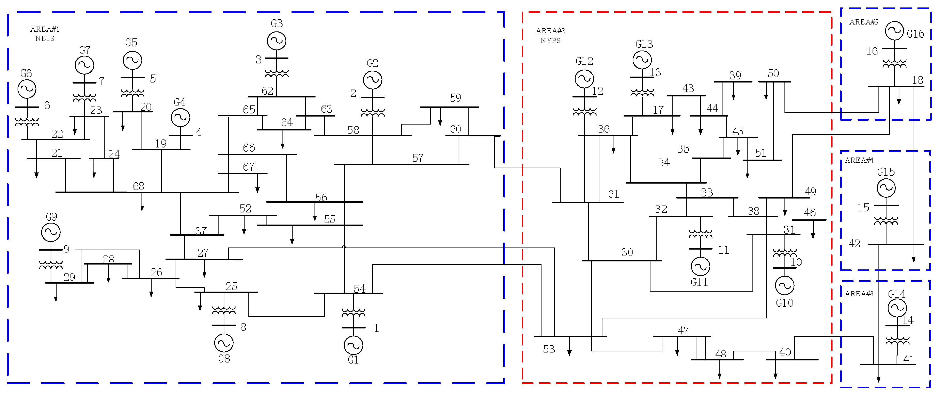
The IEEE 16-machine 68-bus system [17] was adopted to implement the simulation analysis. The system consists of five areas: the New England test system (NETS), the New York power system (NYPS) and its three adjacent systems, as shown in Figure 2. Among them, the New England system (NETS) is Area 1 comprising nine generators, named G1–G9. The system power flows, SG models, their parameters and excitation systems and power system stabilizers (PSS) are described in [17].
The PSS/E was adopted to implement the simulation analysis. Fifteen electromechanical modes in the original system were identified and are listed in Table 1. Among these electromechanical modes, four interarea modes, their corresponding eigenvalues, oscillation frequencies, damping ratios and associated generators are shown in the first four lines in bold in Table 1. From Table 1, it can be observed that interarea modes are involved with several interarea SGs—their frequencies change from 0.3619 to 0.7926 Hz—but only a few local SGs participate in the other 11 local modes, with frequencies between 1.0113 and 1.7944 Hz.
4.1. Impact of the Increasing Penetration Levels of Type 4 WTGs on Traditional Interarea Modes
The capacities of generators G1–G9 in the NETS area of the system are 250, 545, 650, 632, 505, 700, 560, 540, 800 MW. To study the impact of the Type 4 WTG-based TMMC on the small-signal performance of power systems, the synchronous generators, G9–G2, in the NETS area are gradually replaced by the equivalent Type 4 WTGs. The eight penetration levels in the NETS area change from 15.44% to 95.18%. The details of the eight penetration levels and the replaced synchronous generators are shown in Table 2. When the largest WTG penetration level of the NETS area is 95.18%, the penetration level of the whole system is 27.7%. In this case, the NETS area is analogous to a Type 4 WTG-based TMMC.
We analyzed and compared the modes for all penetration levels in Table 2. When one conventional synchronous generator is replaced by one Type 4 equivalent WTG, a pair of electromechanical modes relating to the conventional synchronous generator disappears. Moreover, a pair of new electromechanical modes relating to Type 4 WTGs appears. Four interarea modes are still available despite replacement of some conventional synchronous generators in the NETS area, but their damping ratios and frequencies change with increasing penetration levels.
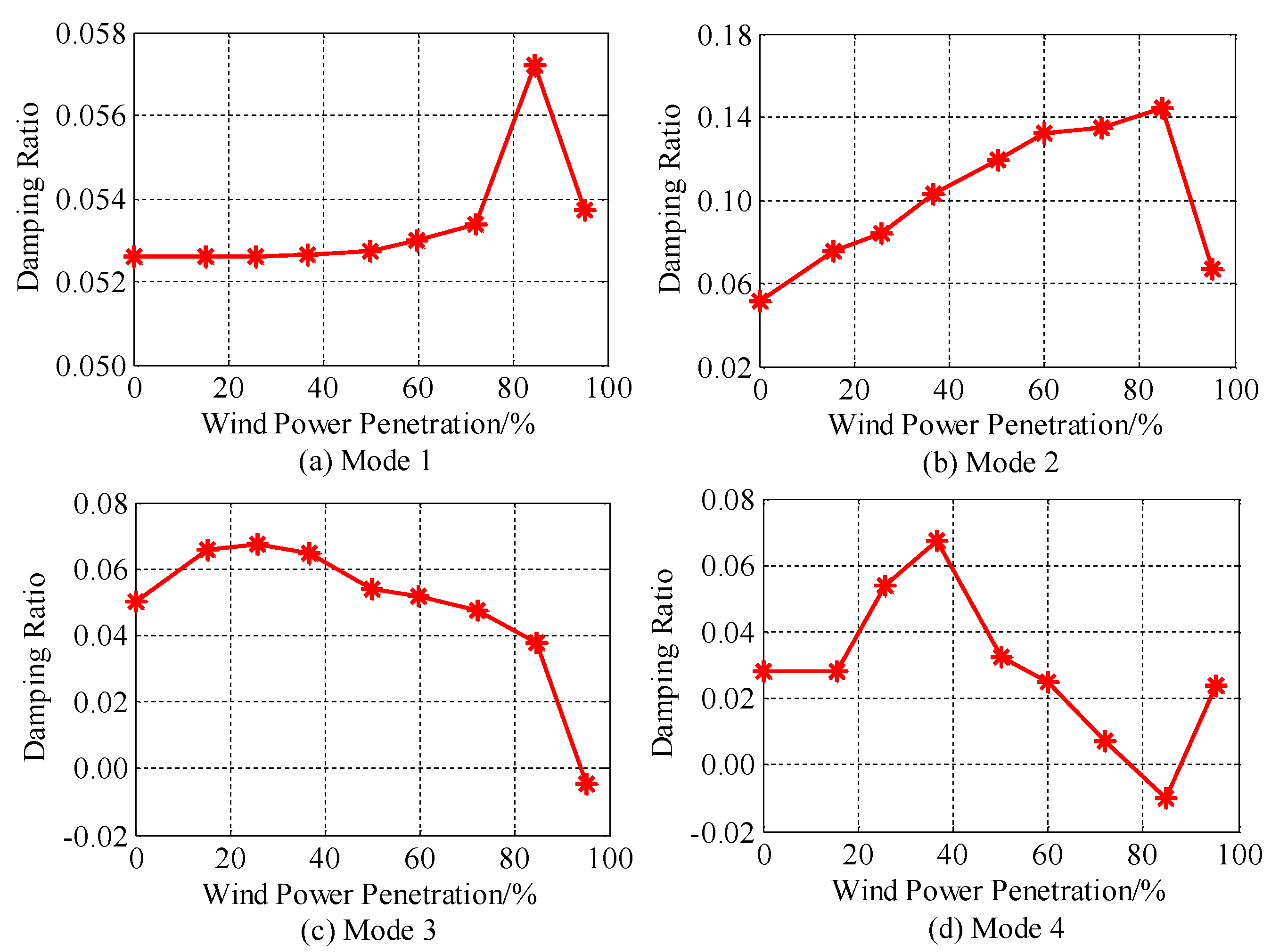
Figure 3 shows that the damping ratios of the four interarea modes vary as the penetration level of Type 4 WTGs in the TMMC increases. It can be observed from Figure 3 that the damping ratio of Mode 1 is generally constant before the penetration level reaching 72.12%, and then it fluctuates with the penetration level increasing in the TMMC. The damping ratio of Mode 2 increases with the increase of the WTG penetration level. However, when the WTG penetration level increases to 84.66%, the damping ratio of Mode 2 begins to decrease. The damping ratios of Modes 3 and 4 fluctuate as the WTG penetration level increases. A high Type 4 WTG penetration level may cause Modes 3 and 4 to become unstable. It can be observed from Figure 3 that, with the increase of the penetration level, the changed law of the damping of interarea modes is inconsistent.
Figure 4 shows that the frequencies of interarea modes change with the increase of WTG penetration levels. The frequency of Mode 1 fluctuates with the increase of penetration levels, while the frequencies of Modes 2, 3 and 4 increase with the increase of penetration levels. The changed law of the damping of interarea modes is also inconsistent with the increase of penetration levels.
Table 3 shows that the state variables of Type 4 WTGs hardly participate in the traditional interarea electromechanical modes. Thus, there is no dynamic interaction between Type 4 WTGs and traditional interarea electromechanical modes. The impact of Type 4 WTGs on traditional interarea modes mainly depends on the system layout, the WTG penetration levels and the replaced synchronous generators, but not on the dynamic interaction of Type 4 WTGs and SGs.
In summary, there is no dynamic interaction between Type 4 WTGs and SGs by interarea modes. With the increase in penetration level in the NETS area, the SGs that participate in the area modes may be replaced. Thus, for each penetration level, the participation SGs are different for the area modes. This can result in an inconsistent law, where the damping ratios or frequencies of four interarea modes may increase or decrease with the increase of penetration levels. Thus, integration of Type 4 WTGs into production-level power systems may result in the increase of damping of some interarea modes, but the decrease of damping of others. It is difficult to find a law of the influence of the Type 4 WTGs on damping and frequencies of the key modes of production-level power systems.
4.2. Investigation of New Electromechanical Modes Dominated by Type 4 WTGs
As stated above, when one equivalent Type 4 WTG replaces one synchronous generator, a pair of electromechanical modes strongly relating to the synchronous generator vanishes, but a pair of new electromechanical modes strongly relating to the Type 4 WTG appears. The new type of electromechanical modes can be identified by IFi, defined by Equation (5). Table 4 lists the new modes for each penetration level, participating WTGs in descending order of participation factors and identification factors of these new modes.
The numerators of identification factors, IFi, are equal to their denominators in Table 4. This shows that the new electromechanical modes are dominated by the mechanical state variables of Type 4 WTGs. For each penetration level, there exists one electromechanical mode that has the lightest damping and strong interaction with most Type 4 WTGs. They are akin to the conventional interarea modes, but with frequencies higher than conventional interarea modes, here called strong-interaction modes in bold in Table 4. The other several modes are only related to a few WTGs with heavier damping, and they are akin to the conventional local modes, here called weak-interaction modes. The new electromechanical modes involving both strong- and weak-interaction modes have a weak correlation with the electrical control of full converters of Type 4 WTGs.
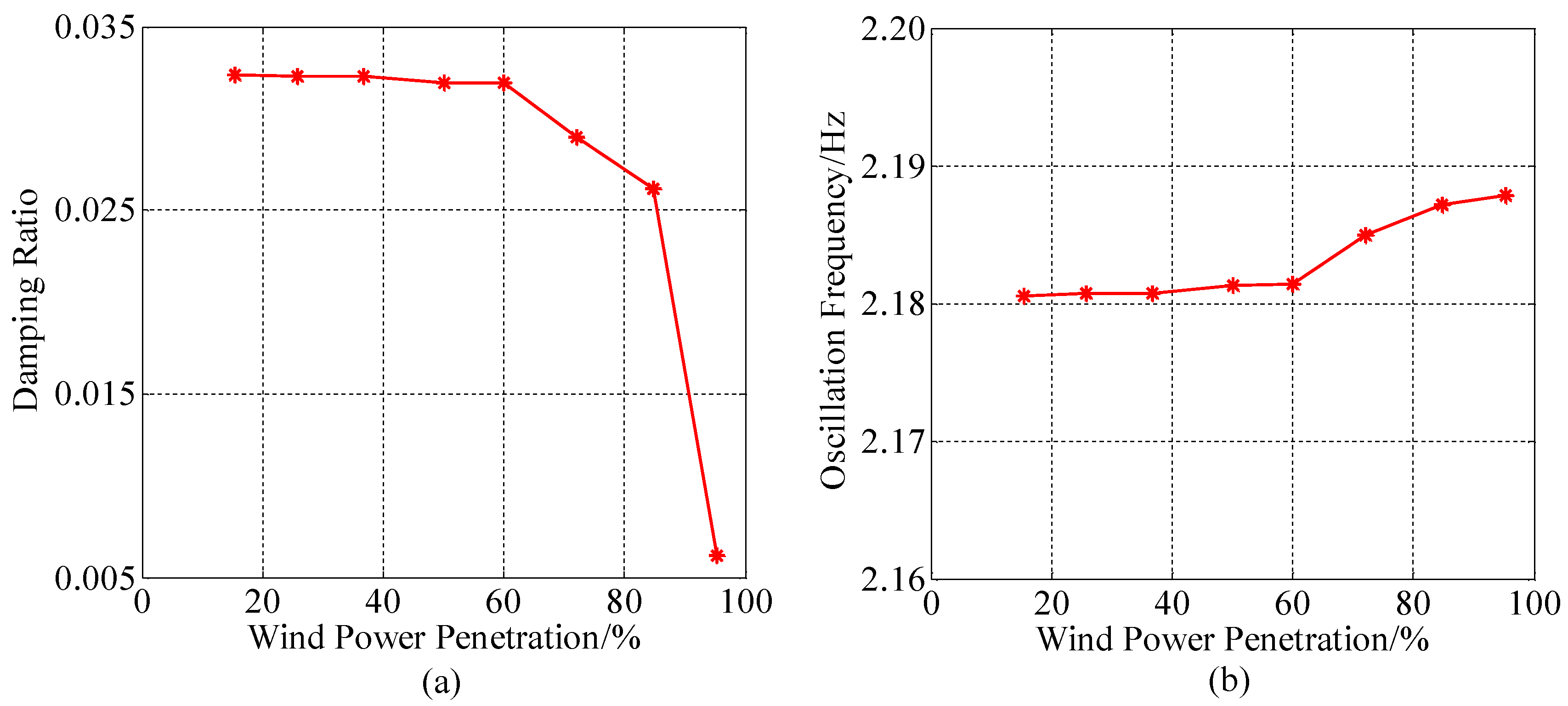
Figure 5a,b show that the damping ratios and frequencies of the strong-interaction modes change with the increasing penetration levels. The new type of strong-interaction mode is governed by most Type 4 WTGs. With the increase of penetration level, the damping of the strong-interaction mode gradually decreases and finally becomes negative because the number of its participating WTGs increases. Their oscillation frequencies are higher than conventional interarea modes. The detailed performance of strong-interaction modes need to be further investigated.
For the wind power penetration level 50.17%, at which G6–G9 are replaced, Table 5 shows the first participation factors larger than 0.1, the corresponding participating WTGs and variables for the strong-interaction mode. It can be seen from Table 5 that the strong-interaction mode strongly relates to equivalent WTGs—G9, G7 and G6. It is also observed from the first larger participation factors that the strong-interaction mode closely relates to δt and ωg of Type 4 WTGs. Therefore, the strong-interaction modes dominated by Type 4 WTGs result from a strong interaction between the power angle and speed of the Type 4 WTGs.
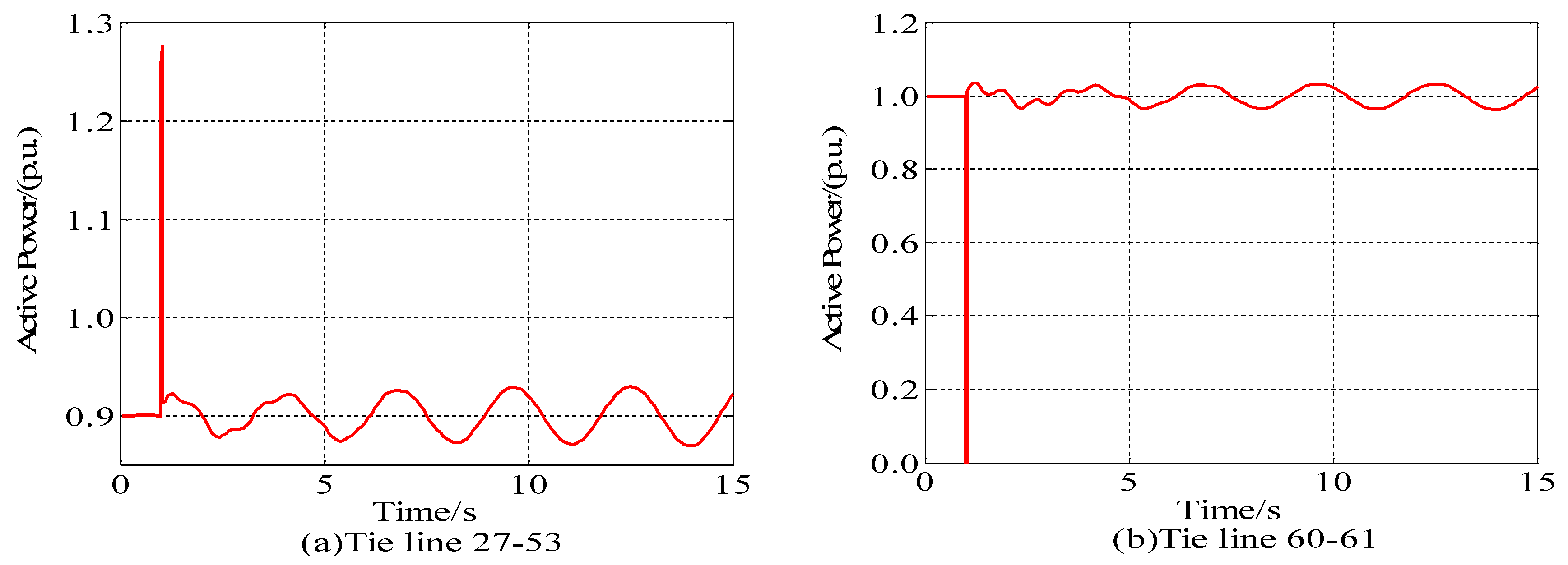
For the wind power penetration level of 50.17%, a three-phase short-circuit fault was applied to bus 49 for a duration period of 0.01 s and then cleared. The power oscillation curves of the related generators and the tie line for 15 s are shown in Figure 6 and Figure 7. Figure 6 shows the active power and reactive power curves of the WTGs G9 and G7. Figure 7 illustrates the active power curves of the interarea tie lines 27–53 and 60–61. The power oscillation curve was analyzed by using the Prony program [18,19] to identify the modes of the power oscillations.
Table 6 shows the Prony analysis results of the power oscillations of Type 4 equivalent WTGs and the interarea tie line. It can be also observed from Table 6 that two oscillation components appear in power oscillations of WTGs and tie lines 27–53, 54–53, 60–61. One oscillation component of about 0.34 Hz is the conventional interarea electromechanical Mode 4. Another oscillation component of about 2.183 Hz is the strong- or weak- interaction mode of the Type 4 WTGs in Table 5. These results show that the new electromechanical modes dominated by WTGs are similar to the traditional electromechanical modes dominated by SGs. They can result in widely spread power oscillations into the grid through the full converter.
In the traditional power system, its power oscillation propagates from the electromechanical modes dominated by SGs. However, according to the above small-signal analysis and signal detection of the time-domain simulation, the new electromechanical modes dominated by the mechanical dynamics of Type 4 WTGs may cause widely spread power oscillations in power systems. The characteristics of these new electromechanical modes are akin to the traditional electromechanical modes dominated by SGs. Moreover, according to the analysis results of Figure 5, with the increase of WTG penetration level, the strong interaction between Type 4 WTGs can result in instability of strong-interaction modes dominated Type 4 WTGs, which was not involved in any previous theoretical analysis. Previous theoretical analysis usually believed that Type 4 WTGs are isolated from the grid through the electronic converters and that their electromechanical dynamics are decoupled from power systems. However, the above analysis in this paper presents a different result.
5. Conclusions
Under the background that the Type 4 WTG-based TMMC has operated in the Northwest Power Grid in China, this paper analyzes the impact of the Type 4 WTG-based TMMCs on small-signal stability using the second-generation GMs of WECC. Integration of the Type 4 WTG-based TMMC into power systems not only has an important impact on the conventional electromechanical modes, but also brings in two new types of electromechanical modes related to the Type 4 WG-based TMMC. The detailed conclusions are given as follows.
(1) There is no dynamic interaction between Type 4 WTGs and SGs. Due to replacement of SGs, the increasing penetration of Type 4 wind power generators may result in stronger damping or also instability of a significant mode. There is no law for the impact of Type 4 WTGs replacing SGs on traditional electromechanical modes.
(2) Although the PMSGs of the Type 4 WTGs are isolated from the grid by their grid-connected converters, one new type of electromechanical mode, strongly dominated by the mechanical states of Type 4 WTGs, is introduced into power systems. The new type of mode is strongly determined by the rotor angle and velocity of the Type 4 WTGs. It can be divided into strong-interaction modes and weak-interaction modes. Multiple equivalent Type 4 WTGs participate in the strong-interaction modes. Also, the strong-interaction modes may lose stability with the increase of penetration. Thus, the strong-interaction modes of Type 4 WTGs have significant impact on the operation security of power systems.
The performance of the new electromechanical modes dominated by Type 4 WTGs need to be further investigated.
Author Contributions
W.C., Z.T., J.Z. and J.Q. equally contributed to this work. W.C., J.Z. and J.Q. presented the idea of this paper and completed the writing and some other work of this paper. Z.T. contributed to the simulations of the performance of the system. The final manuscript was approved by all authors.
Acknowledgments
This work is supported in part by Sino-US international Science and Technology Cooperation Project under Grant 2016YFE0105300
Conflicts of Interest
The authors declare no conflict of interest.
Nomenclature
| WTG | Wind turbine generator |
| TMMC | Ten million megawatt cluster |
| GM | Generic model |
| WECC | Western Electricity Coordinating Council |
| IF | Identification factor |
| regc_a | Generator/converter model |
| reec_a | Electrical control model |
| wtgt_a | Shaft model of wind turbine generator |
| repc_a | Plant-level controller model |
| SG | Synchronous generator |
| AC | Alternative current |
| PI | Participation index |
| PMSG | Permanent magnet synchronous generators |
| NETS | New England test system |
| NYPS | New York power system |
| PSS | Power system stabilizer |
References
- Chouket, M.; Krichen, L. Small signal modeling and stability analysis of wind turbine with PMSG connected to the grid. In Proceedings of the 2015 12th International Multi-Conference on Systems, Signals & Devices (SSD), Mahdia, Tunisia, 16–19 March 2015. [Google Scholar]
- Huang, H.; Mao, C.; Lu, J.; Wang, D. Small-signal modelling and analysis of wind turbine with direct drive permanent magnet synchronous generator connected to power grid. IET Renew. Power Gener. 2012, 6, 48–58. [Google Scholar] [CrossRef]
- Hu, J.; Hu, Q.; Wang, B.; Tang, H.; Chi, Y. Small signal instability of PLL-synchronized type-4 wind turbines connected to high-impedance AC grid during LVRT. IEEE Trans. Energy Convers. 2016, 31, 1676–1687. [Google Scholar] [CrossRef]
- Rimorov, D.; Joós, G.; Kamwa, I. Design and Implementation of Combined Frequency/Oscillation Damping Controller for Type 4 Wind Turbines. In Proceedings of the 2016 Power Systems Computation Conference (PSCC), Genoa, Italy, 20–24 June 2016. [Google Scholar]
- Tan, A.; Lin, X.; Sun, J. A Novel DFIG Damping Control for Power System with High Wind Power Penetration. Energies 2016, 9, 521. [Google Scholar] [CrossRef]
- Shang, L.; Hu, J.; Yuan, X.; Chi, Y. Understanding Inertial Response of Variable-Speed Wind Turbines by Defined Internal Potential Vector. Energies 2017, 10, 22. [Google Scholar] [CrossRef]
- Quintero, J.; Vittal, V.; Heydt, G.T.; Zhang, H. The impact of increased penetration of converter control-based generators on power system modes of oscillation. IEEE Trans. Power Syst. 2014, 29, 2248–2256. [Google Scholar] [CrossRef]
- WECC Renewable Energy Modeling Task Force. Generic Models and Model Validation for Wind and Solar PV Generation: Technical Update; EPRI: Palo Alto, CA, USA, 2011. [Google Scholar]
- WECC Wind Generator Modeling Group. WECC Wind Power Plant Power Flow Modeling Guide; EPRI: Palo Alto, CA, USA, 2008. [Google Scholar]
- WECC Renewable Energy Modeling Task Force. WECC Wind Plant Dynamic Modeling Guidelines; EPRI: Palo Alto, CA, USA, 2014. [Google Scholar]
- Pourbeik, P. Model User Guide for Generic Renewable Energy System Models; EPRI: Palo Alto, CA, USA, 2015. [Google Scholar]
- Muljadi, E.; Ellis, A. Validation of wind power plant dynamic models. In Proceedings of the Power and Energy Society General Meeting-Conversion and Delivery of Electrical Energy in the 21st Century, Pittsburgh, PA, USA, 20–24 July 2008. [Google Scholar]
- Asmine, M.; Brochu, J.; Fortmann, J.; Gagnon, R.; Kazachkov, Y.; Langlois, C.E.; Larose, C.; Muljadi, E.; MacDowell, J.; Pourbeik, P.; et al. Model validation for wind turbine generator models. IEEE Trans. Power Syst. 2011, 26, 1769–1782. [Google Scholar] [CrossRef]
- Brochu, J.; Larose, C.; Gagnon, R. Validation of single- and multiple-machine equivalents for modeling wind power plants. IEEE Trans. Energy Convers. 2011, 26, 532–541. [Google Scholar] [CrossRef]
- Pourbeik, P. Model Validation for Wind and Solar pv Generation, Technical Update; EPRI: Palo Alto, CA, USA, 2011. [Google Scholar]
- Siemens Industry, Inc. PSS/E 34.1 Gui Users Guide; Siemens Industry, Inc.: Schenectady, NY, USA, 2016. [Google Scholar]
- Pal, B.; Chaudhuri, B. Robust Control in Power Systems; Springer Science & Business Media: Berlin, Germany, 2006. [Google Scholar]
- Trudnowski, D.J.; Johnson, J.M.; Hauer, J.F. SIMO system identification from measured ringdowns. In Proceedings of the American Control Conference, Philadelphia, PA, USA, 26–26 June 1998. [Google Scholar]
- Deng, J.; Tu, J.; Chen, W. Identification of critical low frequency oscillation mode in large disturbances. Power Syst. Technol. 2007, 31, 36–41. [Google Scholar]
Figure 1.
Second-generation generic model (GM) of Type 4 wind turbine generators (WTGs): (a) Type 4A; (b) Type 4B; (c) repc_a; (d) reec_a; (e) regc_a; (f) wtgt_a.
Figure 1.
Second-generation generic model (GM) of Type 4 wind turbine generators (WTGs): (a) Type 4A; (b) Type 4B; (c) repc_a; (d) reec_a; (e) regc_a; (f) wtgt_a.


Figure 2.
IEEE 16-machine 68-bus system diagram: with the increasing of wind penetration, the synchronous generators (SGs) of the New England test system (NETS) are gradually replaced by Type 4 WTGs; its behavior is similar to the 10 million megawatt cluster (TMMC).
Figure 2.
IEEE 16-machine 68-bus system diagram: with the increasing of wind penetration, the synchronous generators (SGs) of the New England test system (NETS) are gradually replaced by Type 4 WTGs; its behavior is similar to the 10 million megawatt cluster (TMMC).

Figure 3.
Damping ratios of interarea modes. (a) Mode 1; (b) Mode 2; (c) Mode 3; (d) Mode 4.

Figure 4.
Frequencies of interarea modes vs. wind power penetration. (a) Mode 1; (b) Mode 2; (c) Mode 3; (d) Mode 4.
Figure 4.
Frequencies of interarea modes vs. wind power penetration. (a) Mode 1; (b) Mode 2; (c) Mode 3; (d) Mode 4.

Figure 5.
Damping ratio and frequency of the strong-interaction mode vs. wind power penetration. (a) the damping ratios of the strong-interaction modes; (b) the frequencies of the strong-interaction modes.
Figure 5.
Damping ratio and frequency of the strong-interaction mode vs. wind power penetration. (a) the damping ratios of the strong-interaction modes; (b) the frequencies of the strong-interaction modes.

Figure 6.
Power oscillation of WTGs G9 and G7 under the penetration level of 50.17%. (a) the active power curves of the WTGs G9; (b) the reactive power curves of the WTGs G9; (c) the active power curves of the WTGs G7; (d) the reactive power curves of the WTGs G7.
Figure 6.
Power oscillation of WTGs G9 and G7 under the penetration level of 50.17%. (a) the active power curves of the WTGs G9; (b) the reactive power curves of the WTGs G9; (c) the active power curves of the WTGs G7; (d) the reactive power curves of the WTGs G7.

Figure 7.
Power curve of tie lines for 27–53 and 60–61 under 50.17% wind power penetration. (a) the active power curves of the interarea tie lines 27–53; (b) the active power curves of the interarea tie lines 60–61.
Figure 7.
Power curve of tie lines for 27–53 and 60–61 under 50.17% wind power penetration. (a) the active power curves of the interarea tie lines 27–53; (b) the active power curves of the interarea tie lines 60–61.


Table 1.
Eigenvalues of 16-machine 68-bus original system.
| Mode | Eigenvalues | Frequency (Hz) | Damping Ratio | Participation Generator |
|---|---|---|---|---|
| 1 | −0.2625 ± 4.9801 | 0.7926 | 0.0526 | 15, 14, 16 |
| 2 | −0.1878 ± 3.6787 | 0.5855 | 0.0510 | 13, 16, 14, 6, 12, |
| 3 | −0.1645 ± 3.2708 | 0.5206 | 0.0502 | 16, 14, 13 |
| 4 | −0.0642 ± 2.2737 | 0.3619 | 0.0282 | 15, 14, 16, 13 |
| 5 | −0.4311 ± 6.3543 | 1.0113 | 0.0677 | 3, 2, 6, 5, 7, 4 |
| 6 | −0.1499 ± 6.6674 | 1.0612 | 0.0225 | 9, 3, 8 |
| 7 | −0.4443 ± 6.9603 | 1.1078 | 0.0637 | 12, 13 |
| 8 | −0.5850 ± 7.0540 | 1.1227 | 0.0826 | 5, 6, 7, 4 |
| 9 | −0.2895 ± 7.7299 | 1.2303 | 0.0374 | 10, 9, 1, 8, 12 |
| 10 | −0.6337 ± 7.8369 | 1.2473 | 0.0806 | 2, 3 |
| 11 | −0.3960 ± 8.1306 | 1.2940 | 0.0487 | 10, 1, 8, 9 |
| 12 | −0.9023 ± 9.0836 | 1.4457 | 0.0989 | 7, 6 |
| 13 | −0.7164 ± 9.2516 | 1.4724 | 0.0772 | 8, 1 |
| 14 | −0.9341 ± 9.5130 | 1.5140 | 0.0977 | 4, 5 |
| 15 | −0.7562 ± 11.2750 | 1.7944 | 0.0669 | 11, 10 |
Table 2.
Replaced units and corresponding penetration levels in the New England test system (NETS) area.
Table 2.
Replaced units and corresponding penetration levels in the New England test system (NETS) area.
| Penetration Levels | 15.44% | 25.86% | 36.67% | 50.17% | 59.92% | 72.12% | 84.66% | 95.18% |
| Replaced Generators | G9 | G9, G8 | G9, G8, G7 | G9, G8, G7, G6 | G9, G8, G7, G6, G5 | G9, G8, G7, G6, G5, G4 | G9, G8, G7, G6, G5, G4, G3 | G9, G8, G7, G6, G5, G4, G3, G2 |
Table 3.
WTG participation index (PIi) of interarea modes for the case with the penetration level 50.17% in the NETS area.
Table 3.
WTG participation index (PIi) of interarea modes for the case with the penetration level 50.17% in the NETS area.
| Mode # | WTG PIi |
|---|---|
| 1 | 0/5.428 |
| 2 | 0/8.239 |
| 3 | 0/3.2 |
| 4 | 0/5.55 |
Table 4.
New modes dominated by Type 4 WTGs for different penetration levels in the NETS area.
| Penetration Levels | Eigenvalues | Damping Ratio | Frequency | Participating WTGs | IFi |
|---|---|---|---|---|---|
| 15.44% | −0.4440 ± 13.701 | 0.0324 | 2.1805 | G9 | 1.97/1.97 |
| 25.86% | −0.4428 ± 13.702 | 0.0323 | 2.1807 | G9, G8 | 2.1/2.1 |
| −0.4638 ± 13.693 | 0.0339 | 2.1793 | G8 | 1.97/1.97 | |
| 36.67% | −0.4425 ± 13.702 | 0.0323 | 2.1807 | G9, G8, G7 | 2.1/2.1 |
| −0.4591 ± 13.694 | 0.0335 | 2.1795 | G7 | 1.97/1.97 | |
| −0.4638 ± 13.693 | 0.0338 | 2.1793 | G8 | 1.97/1.97 | |
| 50.17% | −0.4378 ± 13.706 | 0.0319 | 2.1813 | G9, G7, G6 | 3.43/3.43 |
| −0.4479 ± 13.701 | 0.0327 | 2.1806 | G9, G7, G6 | 4.63/4.63 | |
| −0.4627 ± 13.693 | 0.0338 | 2.1793 | G9, G7 | 3.55/3.55 | |
| −0.4637 ± 13.693 | 0.0339 | 2.1793 | G8 | 1.97/1.97 | |
| 59.92% | −0.4374 ± 13.706 | 0.0319 | 2.1814 | G9, G7, G6 | 3.24/3.24 |
| −0.4478 ± 13.701 | 0.0327 | 2.1806 | G9, G7, G6 | 5.1/5.1 | |
| −0.4627 ± 13.693 | 0.0338 | 2.1793 | G6, G7 | 3.59/3.59 | |
| −0.4636 ± 13.693 | 0.0338 | 2.1793 | G8 | 1.97/1.97 | |
| −0.4657 ± 13.691 | 0.0340 | 2.1791 | G5 | 1.97/1.97 | |
| 72.12% | −0.3981 ± 13.729 | 0.0290 | 2.1850 | G6, G7, G9, G4, G5 | 6.91/6.91 |
| −0.4452 ± 13.701 | 0.0325 | 2.1806 | G9, G7 | 2.19/2.19 | |
| −0.4575 ± 13.696 | 0.0334 | 2.1798 | G4, G5, G7, G6 | 4.4/4.4 | |
| −0.4636 ± 13.693 | 0.0338 | 2.1793 | G8 | 1.97/1.97 | |
| −0.4625 ± 13.693 | 0.0338 | 2.1793 | G6, G7 | 3.61/3.61 | |
| −0.4641 ± 13.692 | 0.0339 | 2.1792 | G5, G4 | 3.15/3.15 | |
| 84.66% | −0.3601 ± 13.743 | 0.0262 | 2.1872 | G7, G6, G9, G4, G5, G3 | 7.28/7.28 |
| −0.4450 ± 13.701 | 0.0325 | 2.1806 | G9, G7 | 2.07/2.07 | |
| −0.4571 ± 13.696 | 0.0334 | 2.1798 | G4, G5, G7, G3, G6 | 6.06/6.06 | |
| −0.4582 ± 13.696 | 0.0334 | 2.1797 | G3, G4 | 2.26/2.26 | |
| −0.4635 ± 13.693 | 0.0338 | 2.1793 | G8 | 1.97/1.97 | |
| −0.4624 ± 13.693 | 0.0337 | 2.1793 | G6, G7 | 3.55/3.55 | |
| −0.4640 ± 13.692 | 0.0339 | 2.1792 | G5, G4 | 3.17/3.17 | |
| 95.18%. | −0.0854 ± 13.747 | 0.0062 | 2.1878 | G6, G7, G9, G4, G3, G5, G2 | 8.53/8.53 |
| −0.4448 ± 13.701 | 0.0324 | 2.1806 | G9 | 1.97/1.97 | |
| −0.4510 ± 13.699 | 0.0329 | 2.1803 | G3, G2, G7, G6 | 4.13/4.13 | |
| −0.4573 ± 13.696 | 0.0334 | 2.1798 | G4, G5, G7, G6 | 3.17/3.17 | |
| −0.4616 ± 13.693 | 0.0337 | 2.1794 | G7, G3 | 3.32/3.32 | |
| −0.4635 ± 13.693 | 0.0338 | 2.1793 | G8 | 1.97/1.97 | |
| −0.4621 ± 13.692 | 0.0337 | 2.1792 | G6, G7 | 3.58/3.58 | |
| −0.4638 ± 13.692 | 0.0339 | 2.1791 | G5, G4 | 3.17/3.17 |
Table 5.
Participating WTGs and state variables of the strong-interaction mode for the penetration level 50.17% in the NETS area.
Table 5.
Participating WTGs and state variables of the strong-interaction mode for the penetration level 50.17% in the NETS area.
| Participation Factor | Generator | Module | Related State Variables |
|---|---|---|---|
| 1.00000 | G9 | wtgt_a | The twist angle of the shaft (δt) |
| 0.97162 | G9 | wtgt_a | Generator speed deviation (Δωg) |
| 0.40640 | G7 | wtgt_a | The twist angle of the shaft (δt) |
| 0.39469 | G7 | wtgt_a | Generator speed deviation (Δωg) |
| 0.33489 | G6 | wtgt_a | The twist angle of the shaft (δt) |
| 0.32535 | G6 | wtgt_a | Generator speed deviation (Δωg) |
Table 6.
Results of Prony analysis under the case with the penetration level 50.17%.
| Measured Power | Main Modes | Frequency | Damping Ratio |
|---|---|---|---|
| Active power of G9 | −0.0250 ± 2.1603 | 0.344 | 0.0116 |
| −0.0520 ± 13.8788 | 2.210 | 0.0037 | |
| Reactive power of G9 | 0.0230 ± 2.1164 | 0.337 | −0.0109 |
| −2.6000 ± 13.2508 | 2.110 | 0.1925 | |
| Active power of G8 | 0.0240 ± 2.1478 | 0.342 | −0.0112 |
| −0.0560 ± 13.6276 | 2.170 | 0.0041 | |
| Reactive power of G8 | −0.0320 ± 2.1352 | 0.340 | 0.0150 |
| −6.1000 ± 13.0624 | 2.080 | 0.4231 | |
| Active power of G7 | 0.0620 ± 2.1540 | 0.343 | −0.0288 |
| −0.6000 ± 13.5648 | 2.160 | 0.0442 | |
| Reactive power of G7 | 0.0290 ± 2.1415 | 0.341 | −0.0135 |
| −0.0350 ± 14.9464 | 2.380 | 0.0023 | |
| Active power of G6 | 0.0320 ± 2.1415 | 0.341 | −0.0149 |
| −1.2000 ± 14.8836 | 2.370 | 0.0804 | |
| Reactive power of G6 | 0.0490 ± 2.1917 | 0.349 | −0.0224 |
| −3.0000 ± 13.502 | 2.150 | 0.2169 | |
| Active power of tie line 27–53 | 0.0100 ± 2.1729 | 0.346 | −0.0046 |
| −1.8000 ± 13.8788 | 2.210 | 0.1286 | |
| Active power of tie line 54–53 | 0.0150 ± 2.1854 | 0.348 | −0.0069 |
| −2.0000 ± 15.4488 | 2.460 | 0.1284 | |
| Active power of tie line 60–61 | 0.0230 ± 2.1603 | 0.344 | −0.0106 |
| −2.1000 ± 13.7532 | 2.190 | 0.1509 |
© 2018 by the authors. Licensee MDPI, Basel, Switzerland. This article is an open access article distributed under the terms and conditions of the Creative Commons Attribution (CC BY) license (http://creativecommons.org/licenses/by/4.0/).
Share and Cite
MDPI and ACS Style
Chen, W.; Teng, Z.; Zhao, J.; Qiu, J. Small-Signal Performance of Type 4 Wind Turbine Generator-Based Clusters in Power Systems. Energies 2018, 11, 1486. https://doi.org/10.3390/en11061486
AMA Style
Chen W, Teng Z, Zhao J, Qiu J. Small-Signal Performance of Type 4 Wind Turbine Generator-Based Clusters in Power Systems. Energies. 2018; 11(6):1486. https://doi.org/10.3390/en11061486
Chicago/Turabian StyleChen, Wuhui, Zaixing Teng, Junhua Zhao, and Jing Qiu. 2018. "Small-Signal Performance of Type 4 Wind Turbine Generator-Based Clusters in Power Systems" Energies 11, no. 6: 1486. https://doi.org/10.3390/en11061486
Note that from the first issue of 2016, this journal uses article numbers instead of page numbers. See further details here.