Load-Sensing Pump Design to Reduce Heat Generation of Electro-Hydrostatic Actuator Systems


1
State Key Laboratory of Fluid Power and Mechatronic Systems, Zhejiang University, Hangzhou 310027, China
2
School of Automation Science and Electrical Engineering, Beihang University, Beijing 100191, China
3
Science and Technology on Aircraft Control Laboratory, Beihang University, Beijing 100191, China
*
Author to whom correspondence should be addressed.
Energies 2018, 11(9), 2266; https://doi.org/10.3390/en11092266
Submission received: 31 July 2018
/
Revised: 21 August 2018
/
Accepted: 24 August 2018
/
Published: 29 August 2018
(This article belongs to the Special Issue Energy Efficiency and Controllability of Fluid Power Systems 2018)
Abstract
:The electro-hydrostatic actuator (EHA) with variable pump displacement is considered to be a promising alternative to the currently popular EHA with fixed pump displacement in terms of heat reduction. This paper presents a load-sensing pump for the EHA which requires no additional power source and can adjust its volumetric displacement automatically with load pressure. A load-sensing pump prototype was developed and experiments were carried out on a test rig for it under different operating conditions. In addition, an experimental campaign was performed on an EHA test bench with a load-sensing pump and a fixed displacement pump. The results show that the load-sensing pump can decrease its volumetric displacement automatically at high pressure and thus reduce the heat generation of EHA system effectively.
1. Introduction
Electro-hydrostatic actuators (EHA) have become popular in more electric aircrafts (MEA) with the development of power-by-wire (PBW) technology [1,2]. The self-contained EHA system has partially replaced the conventional centralized hydraulic system in MEA and provides localized hydraulic power for flight control. This replacement offers substantial advantages for the aircraft, including weight saving, safety and reliability improvement, easier maintenance, and higher efficiency [3,4,5,6,7]. A typical EHA system consists of a bidirectional electric motor, bidirectional hydraulic pump, symmetrical hydraulic actuator, accumulator, and bypass valve [8,9]. The hydraulic pump used is often called an EHA pump [10], which is driven by the electric motor and provides pressurized fluid for the hydraulic actuator to power the flight control surface. The velocity and direction of the hydraulic actuator are controlled by the delivery flow rate of the EHA pump and by the motor rotation direction, respectively.
There are three different concepts for adjusting the flow rate of an EHA pump [11]. The first approach is to change the pump speed, where the flow rate is controlled by the pump speed but the volumetric displacement remains constant. The second method is the variable-displacement pump with a fixed-speed drive, where the flow rate depends only on the volumetric displacement of the pump. The third possibility for controlling the flow rate is a combination of variable speed and variable displacement. In this case, the supplied flow to the hydraulic actuator can be regulated by controlling the pump speed and volumetric displacement simultaneously. Among the above three strategies of flow rate regulation, the third strategy has advantages of better dynamic performance and higher efficiency over the other ones [12,13,14,15].
According to the different combinations of pump and motor in the EHA system, the EHA can be divided into three categories [4]: EHA with fixed pump displacement and variable motor speed (EHA-FPVM), EHA with variable pump displacement and fixed motor speed (EHA-VPFM), and EHA with variable pump displacement and variable motor speed (EHA-VPVM). In these three EHA configurations, the EHA-FPVM is most popular in aerospace applications, because the choice of fixed-displacement pump has great potential for pump size reduction and thus weight saving [4,5,6,7,8,9,16]. However, a major problem with the EHA-FPVM is the large amount of heat generated by the motor [17,18]. It is well known that the armature current is proportional to the motor torque, which depends on the pump displacement and load pressure [19]. When the EHA works at high pressure and low speed, the motor torque will increase significantly, resulting in large armature current and thus great copper and iron losses within the motor. Instead of being carried away by hydraulic fluid, the generated heat can only be cooled in the form of conduction due to the elimination of conventional centralized hydraulic system. As a result, the heat problem limits the application of EHA-FPVM, although it has a higher efficiency than the EHA-VPFM [20,21].
In recent years, the EHA-VPVM is identified as a promising EHA configuration since it combines advantages of both variable displacement and variable speed. Specifically, it offers two control variables, and thus provides a degree of freedom for process control. The delivery flow supplied for the hydraulic actuator can be realized by different combinations of pump displacement and motor speed. It is common to vary the pump displacement by adjusting the swash plate angle using a hydraulic actuator controlled by a servo valve [22]. This method has a fast response, but the additional hydraulic servo system makes the EHA system costly and complex. Alternatively, the swash plate angle of the EHA pump is adjusted by an electrically driven variable displacement mechanism [19,23,24]. For example, the swash plate is directly driven by a DC servo motor instead of a hydraulic actuator, which makes the EHA-VPVM more simplified and reliable, to some extent. However, the added DC servo motor and high-precision gear reduce the economic efficiency and power density of the EHA system.
In this paper, a load-sensing mechanism for the EHA-VPVM pump is presented based on the principle of direct load-sensing control [25]. This mechanism is structurally simple and requires no additional power source. The volumetric displacement of the EHA pump can be decreased automatically as the load pressure increases, which effectively reduces the peak torque and heat generation of the electric motor. In addition, an EHA pump prototype was developed, and tests were carried out to verify the proposed load-sensing design.
2. Mathematical Analysis
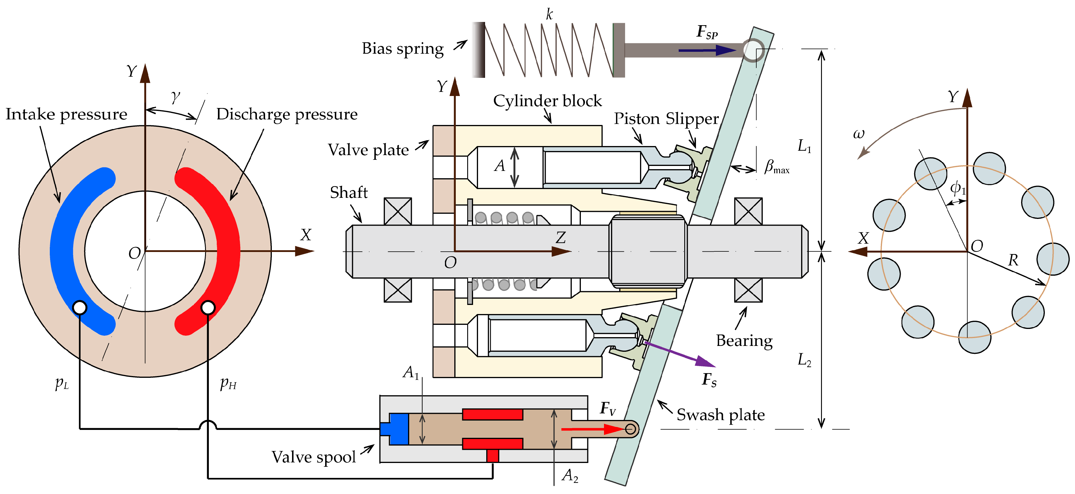
Figure 1 illustrates the schematic diagram of an EHA system with a load-sensing pump. The valve spool and linear spring work together to change the volumetric displacement of the EHA pump. To avoid needing an additional power source, the self-supplied volume flow is taken from the output flow of the pump itself and then acts on the valve spool to drive the swash plate. As a result, the volumetric displacement of the pump can be decreased automatically with the increasing load pressure, thus limiting the peak torque and heat generation of the electric motor.
The bias spring acts as a regulator for the volumetric displacement variation. It works together with the valve spool to implement the required load pressure-volumetric displacement curve, as shown in Figure 2, which is generally derived from the typical force-speed curve of the hydraulic actuator [21,26]. It can be seen from Figure 2 that a full volumetric displacement is maintained at low load pressure (less than pH1), and then the volumetric displacement starts to decrease linearly with load pressure from pH1 to pH2.
For a certain load pressure pH, the volumetric displacement V can be expressed as
where V1 and V2 are the maximum and minimum volumetric displacement, respectively, and pH1 and pH2 are their corresponding load pressures.
As previously stated, the motor torque depends on the volumetric displacement and load pressure of the EHA pump. Considering the intake pressure is negligibly small compared with the load pressure, the motor torque can be approximately expressed as
where ηt is the torque coefficient due to the friction loss of the lubricating interfaces, and TC is the torque loss due to the churning loss of the rotating group within the pump.
The torque coefficient is a function of the operating conditions of the pump, which can be given by [27]
where λi (i = 1, 2, 3, 4) are coefficients, the typical values of which were presented in [27]; μ is the fluid dynamic viscosity; ω is the rotational speed of the pump; and β is the swash plate angle.
The churning loss of the rotating group can be expressed as [28]
where lc and Rc are the length and outer radius of the cylinder block, respectively, t is the gap height between the cylinder block and pump casing, Cd is the drag coefficient, d is the piston diameter, ρ is the fluid density, r is the piston pitch radius, l0 is the piston length out of the cylinder bore at bottom dead center, and α is the angular interval of cylinder bores.
Substituting Equation (1) into Equation (2), the motor torque can be further expressed as
The motor torque reaches its maximum value at a certain operating point (pHm, Vm) as the load pressure varies, as shown in Figure 2. Solving the equation ∂T/∂pH = 0 yields the load pressure pHm for the maximum motor torque, and then, substituting pHm into Equation (5) produces the maximum motor torque.
Figure 3 shows the schematic of the load-sensing EHA pump, which is a swash plate type axial piston pump. There are three types of forces acting on the swash plate, which together determine the rotation of the swash plate about its pivot axis. The bias spring and valve spool are used to control the swash plate angle. Specifically, the bias spring tends to push the swash plate to the location of the maximum inclined angle, while the valve spool attempts to drive the swash plate into a de-stroke position. In addition, the reaction force between the swash plate and slippers also contributes to the swash plate balance.
Neglecting the inertia of the swash plate [29,30] and statically summing the moments acting on the swash plate by the above three forces yield the governing equation for the rotation of swash plate about its pivot axis.
where FSP is the bias spring force, FV is the valve spool force, L1 is the moment arm of FSP, L2 is the moment arm of FV, and TS is the swivel torque due to the reaction force FS between the swash plate and slippers. In this case, L1 = L2 = L.
The bias spring force is given by
where k is the spring stiffness, x0 is the initial compressed length of the spring, and βmax is the maximum swash plate angle.
The valve spool force is given by
where pL is the intake pressure, A1 and A2 are the cross areas of the valve spool. Considering the bidirectional EHA pump, A1 and A2 should satisfy the relationship A2 = 2A1.
The swivel torque acting on the swash plate consists of two components; one results from the displacement chamber pressure and the other one the inertia of piston-slipper assemblies. Therefore, it can be expressed as [31,32,33]
where N is the number of pistons, MPS is the total mass of a single piston-slipper assembly, A is the pressurized area of the piston, and γ is the pressure carry-over angle on the valve plate. Please note that Equation (9) has been linearized for small values of β and γ.
Once again, neglecting the intake pressure and substituting Equations (7) to (9) into Equation (6) yields the following equation:
The spring stiffness and initial compressed length are two important parameters for this load-sensing mechanism. Eliminating x0 by combining two special operating points presented in Figure 2, i.e., (pH1, V1) and (pH2, V2), the bias spring stiffness can be given by
where G is the volumetric displacement gain of the pump, which is defined as G = V/β.
Letting β = βmax and pH = pH1 in Equation (10), the initial compressed length of the bias spring can be expressed as
The first term in Equation (11) or Equation (12) represents a major pressure effect due to the load pressure. The second term represents a minor pressure effect as a result of the pressure transition between two ports on the valve plate. In addition, the third term stands for an inertial effect of the piston-slipper assemblies which is highly dependent on the rotational speed of pump.
It must be pointed out that the inertial terms in Equations (13) and (14) cause a varying k and x0 for different rotational speeds. Therefore, in practice one may design the bias spring for the most used rotational speed of the EHA pump.
3. Results and Discussion
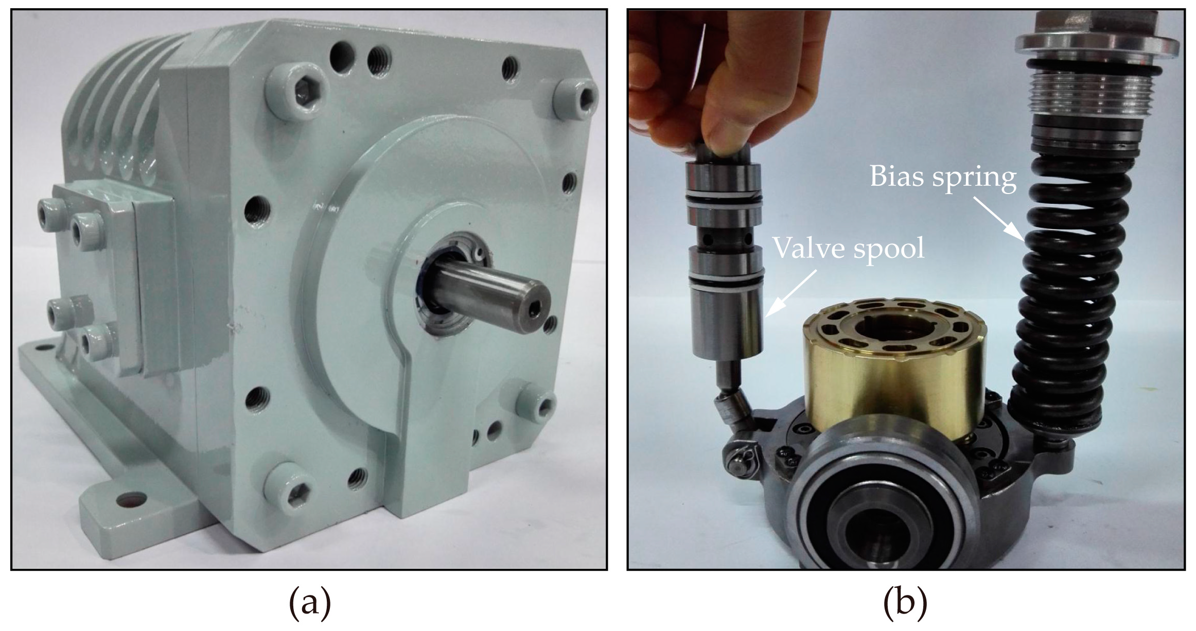
To verify the proposed load-sensing mechanism, an EHA pump prototype (see Figure 4) was developed in the State Key Laboratory of Fluid Power and Mechatronic Systems, Zhejiang University. In addition, a test rig was built for this pump prototype to carry out experiments under different operating conditions, as shown in Figure 5. Transducers were installed in the pump prototype to monitor its performance. The torque/speed transducer was used to measure the torque and speed of the electric motor. Three temperature transducers were responsible for temperature measurements of the intake port, outlet port, and drain port. The pressures of the above three pump ports were measured by three pressure transducers. The discharge and drain flows were obtained by two flow meters. A detailed description of the test rig has been presented in the literature [35].
Figure 6a shows the experimental results of p-V curves for different rotational speeds. At first, the investigated EHA pump works at full volumetric displacement when the load pressure is relatively low. Then the volumetric displacement starts to drop with the increasing load pressure with the help of the load-sensing mechanism. Compared with the theoretical curve, the similarity of the tendencies of both experimental curve indicates that the proposed load-sensing mechanism enables the EHA pump prototype to adjust its volumetric displacement automatically with load pressure as expected. However, the actual p-V curves differ slightly from each other in the turning point for different rotational speeds. This can be explained by the following expression, which is derived from Equation (14).
It is clear from Equation (15) that the critical pressure at the turning point is affected not only by the spring stiffness and initial compressed length, but also by the rotational speed. The critical pressure increases with the increasing spring stiffness and initial compressed length. For a given pump geometry, the critical pressure will increase with the rotational speed, as shown in Figure 6b. This means that when the investigated EHA pump operates at a higher rotational speed, its volumetric displacement has to start decreasing at a greater load pressure, i.e., p H1(1) < p H1(2) < p H1(3).
In Figure 6a the slope of the actual p-V curve becomes greater for higher rotational speeds, which indicates that the volumetric displacement of the pump drops faster with the increasing load pressure as the rotational speed rises. This can be partially explained by the following expression, which is derived from Equation (13).
It can be seen from Equation (16) that both the spring stiffness and rotational speed influence the decreasing slope of the p-V curve. The volumetric displacement of the pump drops more slowly with the increasing spring stiffness, while it drops faster with increasing rotational speed. In addition, the partial filling of cylinders due to the gaseous cavitation [36,37] is another contributor to the faster drop in volumetric displacement for higher rotational speeds. As a result, for a given pump geometry, the volumetric displacement of the pump drops faster as the rotational speed rises, i.e., tanθ1 < tanθ2 < tanθ3.
As shown in Figure 7, the actual p-T curves have a similar tendency to those theoretical curves. The experimental motor torque is greater than the calculated one for each rotational speed. This is because the theoretical calculation does not include the torque loss in the shaft bearings and seals or the torque loss associated with drag due to fluid flow from inlet to outlet, since they are difficult to mathematically model [38]. Another possible cause is the discrepancy between the empirical and actual values of the coefficient λi in Equation (3), because the actual coefficient λi generally varies from one pump to another.
It is observed that the motor torque increases with the increasing rotational speed, which is considered to be caused by the churning loss of the EHA pump [28]. In addition, the torque peak is found to occur at lower critical pressures for higher rotational speeds, i.e., pHm(1) > pHm(2) > pHm(3). This is because as the rotational speed rises, the critical pressure pH1 increases, as shown in Figure 6a, and the increased critical pressure leads to a decreased pressure for the torque peak.
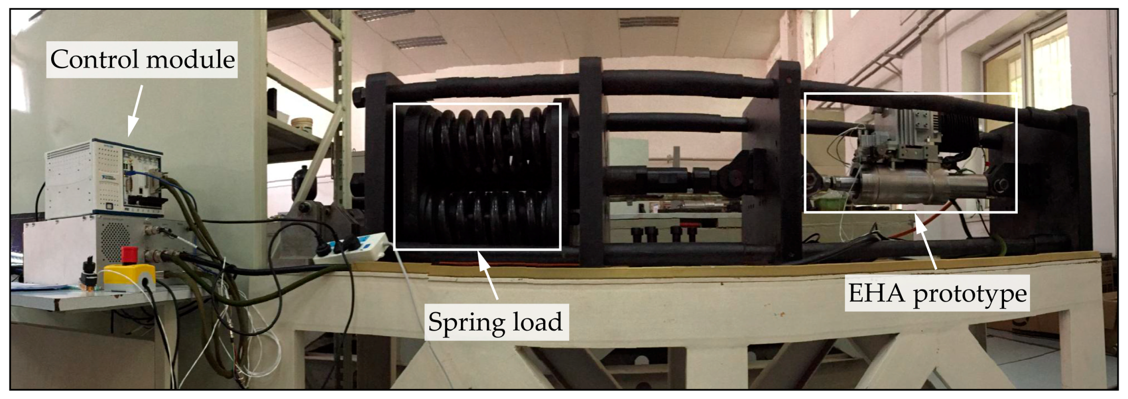
A test bench [39] (see Figure 8) was built to compare the motor heat between the EHA prototypes with fixed-displacement and load-sensing pumps. These two investigated EHA pumps had almost the same design except the pump displacement. The load-sensing pump was a variable displacement pump, while the other one was a fixed-displacement pump that was modified from the load-sensing pump. The piston rod of the hydraulic actuator was connected to a spring load with a stiffness of 1744 N/mm.
After receiving the command signal from the control module, the piston rod was extended out of the cylinder and then maintained at a certain position, as shown in Figure 9a. Then the compressed spring applied a load on the hydraulic actuator. The armature current of the electric motor was recorded to calculate the copper loss of the electric motor.
In practice, the power loss of the electric motor consists of three parts: the copper loss due to the resistance of stator windings, the iron loss due to the eddy current and hysteresis of the stator core, and the mechanical loss of the armature core. The copper and iron losses are dissipated and converted to heat, and the motor heat mainly comes from the copper loss [25,40]. Therefore, in this work, the motor heat is approximately represented by the copper loss W, which is given by [40]
where I is the armature current of electric motor, R is the resistance of stator windings.
Figure 9b shows the comparison of motor heat for two types of EHA pumps. It is clear that the load-sensing design of the EHA pump can effectively reduce the motor heat.
On the other hand, the armature current is also an indicator of the motor torque which is the proportional to the armature current [19,40].
where K is the torque coefficient.
It can be seen from Equations (17) and (18) that decreasing the motor torque can limit the copper loss and thus reduce the motor heat. Furthermore, the motor torque is proportional to the pump displacement and load pressure. The load-sensing design allows the pump displacement to be reduced under high load conditions. This explains why the proposed load-sensing pump can lower the copper loss and heat dissipation of the electric motor in the EHA system compared with the traditional fixed-displacement pump.
4. Conclusions
In this paper, a load-sensing design with no additional power source has been proposed for the EHA pump to reduce the heat generation of the EHA system. The present research includes the theoretical modeling and experimental validation for the load-sensing pump.
The load-sensing design enables the EHA pump to decrease its volumetric displacement automatically with the load pressure, and thus reduces the motor toque and heat generation significantly. The bias spring stiffness and initial compressed length are two critical parameters for the load-sensing design because they determine the turning point and decreasing slope of the p-V curve. The experimental results show that the rotational speed affects the actual p-V and p-T curves of the load-sensing pump. Specifically, for higher rotational speeds the turning point of the p-V curve occurs at a higher critical pressure, and then the pump displacement drops faster with the increasing load pressure; while as the rotational speed rises, the motor torque increases and the peak torque occurs at a lower load pressure.
Future work includes attempting another similar load-sensing design in which the bias spring and valve spool are located on the same side. This alternative configuration would allow the EHA pump to be more compact, thus decreasing the package size of EHA systems.
Author Contributions
J.Z. and B.X. conceived and designed the EHA pump prototype; Q.C. performed the experiments on the EHA pump prototype and wrote the paper. Y.S. and Z.J. conceived and designed the EHA system; Z.L. performed the test of the EHA system and analyzed the data. Y.S., Z.J., and Z.L. contributed to the revision of this paper.
Funding
This research was funded by the National Basic Research Program of China (973 Program) [Grant No. 2014CB046400], the National Natural Science Foundation of China [Grant No. U1737110], and the National Natural Science Foundation of China [Grant No. 51605425].
Conflicts of Interest
The authors declare no conflict of interest.
Nomenclature
| A | pressurized area of a single piston, m2 |
| A1 | cross area of valve spool, m2 |
| A2 | another cross area of valve spool, m2 |
| Cd | drag coefficient |
| d | piston diameter, m |
| FS | reaction force between swash plate and slippers, N |
| FSP | bias spring force, N |
| FV | valve spool force, N |
| G | volumetric displacement gain, m3/rad2 |
| I | armature current of electric motor, A |
| K | torque coefficient, Nm/A |
| k | bias spring stiffness, N/m |
| L | moment arm of FSP and FV, m |
| l0 | piston length out of the cylinder bore at bottom dead center, m |
| lc | length and the cylinder block, m |
| MPS | total mass of a single piston-slipper assembly, kg |
| N | number of pistons |
| pH | load pressure, Pa |
| pL | intake pressure, Pa |
| pH1 | load pressure for maximum volumetric displacement, Pa |
| pH2 | load pressure for minimum displacement, Pa |
| pHm | load pressure for maximum torque, Pa |
| R | resistance of stator windings, Ω |
| Rc | outer radius of the cylinder block, m |
| r | piston pitch radius, m |
| T | motor torque, Nm |
| t | gap height between the cylinder block and pump casing, m |
| TC | torque loss due to the churning loss of rotating group, Nm |
| TS | swivel torque produced by FS, Nm |
| Tmax | maximum motor torque, Nm |
| V | volumetric displacement, m3/rad |
| V1 | maximum volumetric displacement, m3/rad |
| V2 | minimum volumetric displacement, m3/rad |
| Vm | volumetric displacement for maximum torque, m3/rad |
| W | copper loss, J |
| x0 | initial compressed length of the bias spring, m |
| α | angular interval of cylinder bores |
| β | swash plate angle, rad |
| βmax | maximum swash plate angle, rad |
| γ | pressure carry-over angle on valve plate, rad |
| ηt | torque coefficient |
| λi | coefficient of ηt |
| μ | fluid dynamic viscosity, Pa·s |
| ρ | fluid density, kg/m3 |
| ω | rotational speed of pump, rad/s |
Abbreviations
| EHA | electro-hydrostatic actuator |
| EHA-FPVM | EHA with fixed pump displacement and variable motor speed |
| EHA-VPFM | EHA with variable pump displacement and fixed motor speed |
| EHA-VPVM | EHA with variable pump displacement and variable motor speed |
| MEA | more electric aircraft |
| PBW | power-by-wire |
References
- Roboam, X.; Sareni, B.; De Andrade, A. More electricity in the air: Toward optimized electrical networks embedded in more-electrical aircraft. IEEE Ind. Electron. Mag. 2012, 6, 6–17. [Google Scholar] [CrossRef]
- Maré, J.C.; Fu, J. Review on signal-by-wire and power-by-wire actuation for more electric aircraft. Chin. J. Aeronaut. 2017, 30, 857–870. [Google Scholar] [CrossRef]
- Alle, N.; Hiremath, S.S.; Makaram, S.; Subramaniam, K.; Talukdar, A. Review on electro hydrostatic actuator for flight control. Int. J. Fluid Power 2016, 17, 125–145. [Google Scholar] [CrossRef]
- Kang, R.J.; Jiao, Z.X.; Wang, S.P.; Chen, L.S. Design and simulation of electro-hydrostatic actuator with a built-in power regulator. Chin. J. Aeronaut. 2009, 22, 700–706. [Google Scholar] [CrossRef]
- Crowder, R.; Maxwell, C. Simulation of a prototype electrically powered integrated actuator for civil aircraft. Proc. Inst. Mech. Eng. Part G-J. Aerosp. Eng. 1997, 211, 381–394. [Google Scholar] [CrossRef]
- Chakraborty, I.; Mavris, D.N.; Emeneth, M.; Schneegans, A. A methodology for vehicle and mission level comparison of More Electric Aircraft subsystem solution: Application to the flight control actuation system. Proc. Inst. Mech. Eng. Part G-J. Aerosp. Eng. 2015, 229, 1088–1102. [Google Scholar] [CrossRef]
- Van den Bossche, D. The A380 flight control electro hydrostatic actuators, achievements and lessons learnt. In Proceedings of the 25th International Congress of the Aeronautical Sciences, Hamburg, Germany, 3–8 September 2006. [Google Scholar]
- Navarro, R. Performance of an electro-hydrostatic actuator on the F-18 systems research aircraft. In Proceedings of the 16th Digital Avionics Systems Conference, Irvine, CA, USA, 26–30 October 1997. [Google Scholar]
- Habibi, S.; Goldenberg, A. Design of a new high-performance electrohydraulic actuator. IEEE-ASME Trans. Mechatron. 2000, 5, 158–164. [Google Scholar] [CrossRef]
- Zhang, J.H.; Chao, Q.; Xu, B. Analysis of the cylinder block tilting inertia moment and its effect on the performance of high-speed electro-hydrostatic actuator pumps of aircraft. Chin. J. Aeronaut. 2018, 31, 169–177. [Google Scholar] [CrossRef]
- Huang, J.H.; Yan, Z.; Quan, L.; Lan, Y.; Gao, Y.S. Characteristics of delivery pressure in the axial piston pump with combination of variable displacement and variable speed. Proc. Inst. Mech. Eng. Part I-J Syst Control Eng. 2015, 229, 599–613. [Google Scholar] [CrossRef]
- Lovrec, D.; Ulaga, S. Pressure control in hydraulic systems with variable or constant pumps? Exp. Tech. 2007, 31, 33–41. [Google Scholar] [CrossRef]
- Tašner, T.; Les, K.; Tič, V.; Lovrec, D. Energy efficiency of different electrohydraulic drives. In Proceedings of the 9th International Fluid Power Conference, Aachen, Germany, 24–26 March 2014; pp. 14–25. [Google Scholar]
- Willkomm, J.; Wahler, M.; Weber, J. Process-adapted control to maximize dynamics of speed-and displacement-variable pumps. In Proceedings of the ASME/BATH 2014 Symposium on Fluid Power and Motion Control, Bath, UK, 10–12 September 2014. [Google Scholar] [CrossRef]
- Willkomm, J.; Wahler, M.; Weber, J. Potentials of speed and displacement variable pumps in hydraulic applications. In Proceedings of the 10th International Fluid Power Conference, Dresden, Germany, 8–10 March 2016; pp. 379–391. [Google Scholar]
- Mare, J.C.; Vinson, G.; Prado, T.; Combacau, M. Modelling and simulating the pump of an aerospace electro-hydrostatic module for fault detection and identification purposes. In Proceedings of the ASME/BATH 2014 Symposium on Fluid Power and Motion Control, Bath, UK, 10–12 September 2014. [Google Scholar] [CrossRef]
- Chen, W.Z.; Lin, T.; Hill, B.P.; Brown, J.R. Thermal modelling of a flight-critical electrohydrostatic actuator. In Proceedings of the Aerospace Atlantic Conference and Exposition, Dayton, OH, USA, 23–25 May 1995. [Google Scholar]
- Anderson, J.A. Variable displacement electro-hydrostatic actuator. In Proceedings of the IEEE 1991 National Aerospace and Electronics Conference, Dayton, OH, USA, 20–24 May 1991; pp. 529–534. [Google Scholar] [CrossRef]
- Gao, B.; Fu, Y.L.; Pei, Z.C.; Ma, J.M. Research on dual-variable integrated electro-hydrostatic actuator. Chin. J. Aeronaut. 2006, 19, 77–82. [Google Scholar] [CrossRef]
- Andersson, J.; Krus, P.; Nilsson, K. Optimization as a support for selection and design of aircraft actuation systems. In Proceedings of the 7th AIAA/USAF/NASA/ISSMO Symposium on Multidisciplinary Analysis and Optimization, St. Louis, MO, USA, 2–4 September 1998. [Google Scholar]
- Charrier, J.J.; Kulshreshtha, A. Electric actuation for flight and engine control: Evolution and challenges. In Proceedings of the 45th AIAA Aerospace Sciences Meeting and Exhibit, Reno, NV, USA, 8–11 January 2007. [Google Scholar]
- Kim, J.H.; Jeon, C.S.; Hong, Y.S. Constant pressure control of a swash plate type axial piston pump by varying both volumetric displacement and shaft speed. Int. J. Precis. Eng. Manuf. 2015, 16, 2395–2401. [Google Scholar] [CrossRef]
- Zhang, Y.; Fu, Y.L.; Zhou, W.X. Optimal control for EHA-VPVM system based on feedback linearization theory. In Proceedings of the 11th International Conference on Control, Automation, Robotics and Vision, Singapore, 7–10 December 2010; pp. 744–749. [Google Scholar] [CrossRef]
- Fu, Y.L.; Qi, H.T.; Lu, Y.L.; Guo, R.S.; Li, Z.F.; Xue, J.; Yang, Q. A novel electrical servo variable displacement hydraulic pump used for integrated actuator in MEA. In Proceedings of the 28th Congress of the International Council of the Aeronautical Sciences, Brisbane, Australia, 23–28 September 2012. [Google Scholar]
- Song, Z.N.; Jiao, Z.X.; Shang, Y.X.; Wu, S.; Hu, W.N. Design and analysis of a direct load sensing electro-hydrostatic actuator. In Proceedings of the 2015 International Conference on Fluid Power and Mechatronics, Harbin, China, 5–7 August 2015; pp. 624–627. [Google Scholar] [CrossRef]
- Frischemeier, S. Electrohydrostatic actuators for aircraft primary flight control-types, modelling and evaluation. In Proceedings of the 5th Scandinavian International Conference on Fluid Power, Linkoping, Sweden, 28–30 May 1997. [Google Scholar] [CrossRef]
- Manring, N.D. Fluid Power Pumps and Motors: Analysis, Design and Control, 1st ed.; McGraw-Hill Education: New York, NY, USA, 2013; pp. 107–116. [Google Scholar]
- Zhang, J.H.; Li, Y.; Xu, B.; Pan, M.; Lv, F. Experimental study on the influence of the rotating cylinder block and pistons on churning losses in axial piston pumps. Energies 2017, 10, 662. [Google Scholar] [CrossRef]
- Akers, A.; Zeiger, G. Torque on the swashplate of an axial piston pump. J. Dyn. Syst. Meas. Control-Trans. ASME 1985, 107, 220–226. [Google Scholar] [CrossRef]
- Kim, S.D.; Cho, H.S.; Lee, C.O. A parameter sensitivity analysis for the dynamic model of a variable displacement axial piston pump. Proc. Inst. Mech. Eng. Part C-J. Mech. Eng. Sci. 1987, 201, 235–243. [Google Scholar] [CrossRef]
- Manring, N.D.; Johnson, R.E. Modeling and designing a variable-displacement open-loop pump. J. Dyn. Syst. Meas. Control-Trans. ASME 1996, 118, 267–271. [Google Scholar] [CrossRef]
- Manring, N.D. The control and containment forces on the swash plate of an axial-piston pump. J. Dyn. Syst. Meas. Control-Trans. ASME 1999, 121, 599–605. [Google Scholar] [CrossRef]
- Manring, N.D. Designing a control and containment device for cradle-mounted, transverse-actuated swash plates. J. Mech. Des. 2001, 123, 447–455. [Google Scholar] [CrossRef]
- Manring, N.D. The torque on the input shaft of an axial-piston swash-plate type hydrostatic pump. J. Dyn. Syst. Meas. Control-Trans. ASME 1998, 120, 57–62. [Google Scholar] [CrossRef]
- Xu, B.; Chao, Q.; Zhang, J.H.; Chen, Y. Effects of the dimensional and geometrical errors on the cylinder block tilt of a high-speed EHA pump. Meccanica 2017, 52, 2449–2469. [Google Scholar] [CrossRef]
- Bügener, N.; Klecker, J.; Weber, J. Analysis and improvement of the suction performance of axial piston pumps in swash plate design. Int. J. Fluid Power 2014, 15, 153–167. [Google Scholar] [CrossRef]
- Kunkis, M.; Weber, J. Experimental and numerical assessment of an axial piston pump’s speed limit. In Proceedings of the BATH/ASME 2016 Symposium on Fluid Power and Motion Control, Bath, UK, 7–9 September 2016. [Google Scholar] [CrossRef]
- Zecchi, M.; Mehdizadeh, A.; Ivantysynova, M. A novel approach to predict the steady state temperature in ports and case of swash plate type axial piston machines. In Proceedings of the 13th Scandinavian International Conference on Fluid Power, Linköping, Sweden, 3–5 June 2013; pp. 177–187. [Google Scholar] [CrossRef]
- Li, Z.H.; Shang, Y.X.; Jiao, Z.X.; Lin, Y.; Wu, S.; Li, X.B. Analysis of the dynamic performance of an electro-hydrostatic actuator and improvement methods. Chin. J. Aeronaut. 2018. [Google Scholar] [CrossRef]
- Hu, W.N.; Zhou, L.; Tian, Y.S.; Jiao, Z.X.; Shang, Y.X.; Song, Z.N.; Yan, L. Analysis for the power loss of electro hydrostatic actuator and hydraulic actuator. In Proceedings of the 2015 IEEE International Conference on Advanced Intelligent Mechatronics (AIM), Busan, South Korea, 7–11 July 2015; pp. 613–616. [Google Scholar] [CrossRef]
Figure 1.
Schematic diagram of an electro-hydrostatic actuator (EHA) system with load-sensing pump.

Figure 2.
Relationship between load pressure and volumetric displacement or motor torque.

Figure 3.
Schematic of the EHA pump with a load-sensing mechanism.

Figure 4.
EHA pump prototype with a load sensing mechanism: (a) EHA pump prototype; (b) Load-sensing mechanism.
Figure 4.
EHA pump prototype with a load sensing mechanism: (a) EHA pump prototype; (b) Load-sensing mechanism.

Figure 5.
Experiments on the pump prototype: (a) Transducers installed in the pump prototype; (b) Test rig for the pump prototype.
Figure 5.
Experiments on the pump prototype: (a) Transducers installed in the pump prototype; (b) Test rig for the pump prototype.
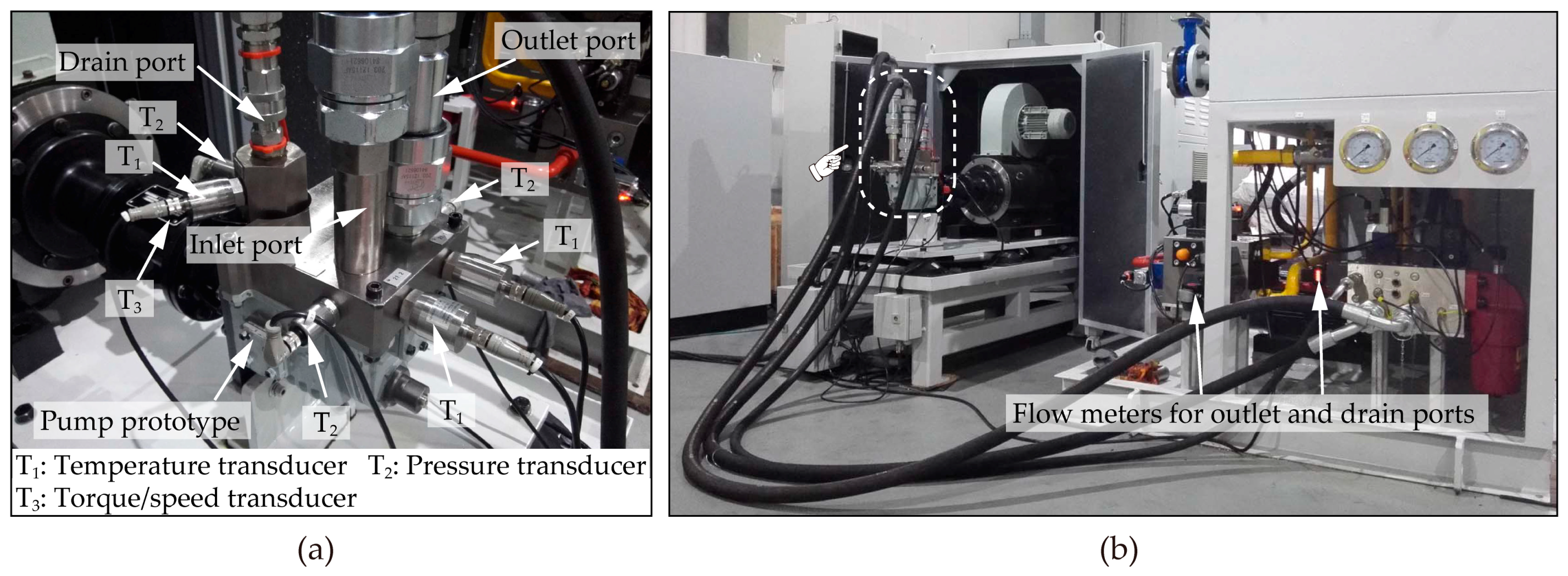
Figure 6.
Influence of rotational speed on the p-V curve: (a) Experimental p-V curves; (b) Variation of the critical pressure with rotational speed.
Figure 6.
Influence of rotational speed on the p-V curve: (a) Experimental p-V curves; (b) Variation of the critical pressure with rotational speed.
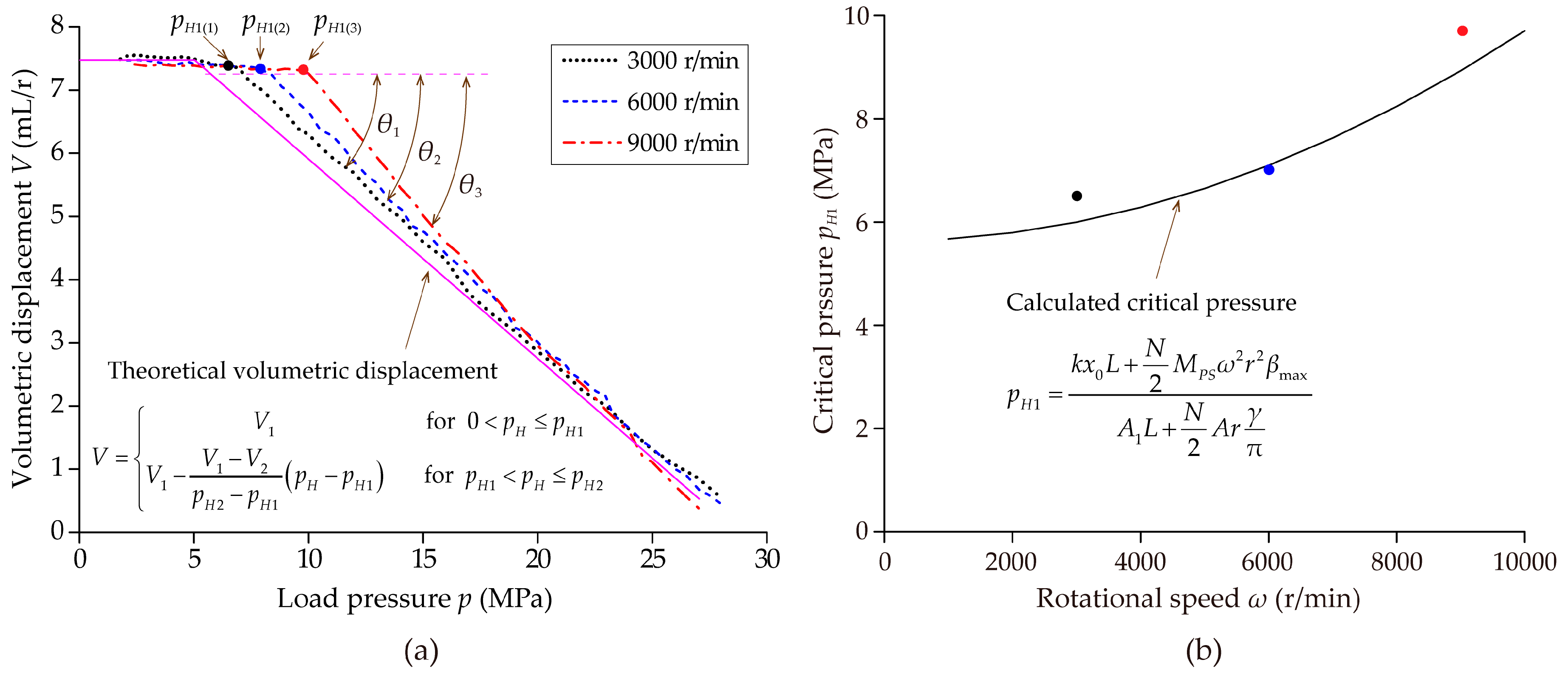
Figure 7.
Relationship between motor torque and rotational speed.

Figure 8.
Test bench for the EHA prototype.

Figure 9.
Experimental results for the EHA prototype: (a) Comparison of the hydraulic actuator displacement; (b) Comparison of the copper loss.
Figure 9.
Experimental results for the EHA prototype: (a) Comparison of the hydraulic actuator displacement; (b) Comparison of the copper loss.

© 2018 by the authors. Licensee MDPI, Basel, Switzerland. This article is an open access article distributed under the terms and conditions of the Creative Commons Attribution (CC BY) license (http://creativecommons.org/licenses/by/4.0/).
Share and Cite
MDPI and ACS Style
Chao, Q.; Zhang, J.; Xu, B.; Shang, Y.; Jiao, Z.; Li, Z. Load-Sensing Pump Design to Reduce Heat Generation of Electro-Hydrostatic Actuator Systems. Energies 2018, 11, 2266. https://doi.org/10.3390/en11092266
AMA Style
Chao Q, Zhang J, Xu B, Shang Y, Jiao Z, Li Z. Load-Sensing Pump Design to Reduce Heat Generation of Electro-Hydrostatic Actuator Systems. Energies. 2018; 11(9):2266. https://doi.org/10.3390/en11092266
Chicago/Turabian StyleChao, Qun, Junhui Zhang, Bing Xu, Yaoxing Shang, Zongxia Jiao, and Zhihui Li. 2018. "Load-Sensing Pump Design to Reduce Heat Generation of Electro-Hydrostatic Actuator Systems" Energies 11, no. 9: 2266. https://doi.org/10.3390/en11092266
Note that from the first issue of 2016, this journal uses article numbers instead of page numbers. See further details here.