Diesel-Injection Equipment Parts Deterioration after Prolonged Use of Biodiesel


1
Vehicle Mechanical Engineering Dept., Alexandrion TEI of Thessaloniki, 57400 Thessaloniki, Greece
2
Mechanical Engineering Department, University of Thessaly, 38334 Volos, Greece
*
Author to whom correspondence should be addressed.
Energies 2019, 12(10), 1953; https://doi.org/10.3390/en12101953
Submission received: 27 March 2019
/
Revised: 10 May 2019
/
Accepted: 14 May 2019
/
Published: 22 May 2019
(This article belongs to the Special Issue Internal Combustion Engines 2018)
Abstract
:The application of biodiesel blends is known to significantly affect operation of diesel-injection equipment, especially the injectors and fuel pump. This paper summarizes experience on this subject from burning fuel blends with high-percentages of biodiesel (up to 70%) on a common-rail, high-pressure-injection diesel engine and a conventional DI engine. Both engines were unable to start after running for 100 h each and staying shut off for more than two months. In order to understand the wear characteristics of the injector nozzle, pump pistons, and elastomer parts (in the case of the high-pressure pump of the common-rail engine), due to the prolonged operation with high-percentage biodiesel blends, their injectors and pumps parts were examined and compared by performing normal photography and low magnification microscopy. Additionally, the various elastomer parts of the high-pressure fuel pump of the common-rail engine were examined for wear and deterioration. The results are compared with existing literature results from other researchers. The observed deterioration of diesel-injection equipment is caused by use of high-percentage biodiesel blends and subsequent engine shut down.
1. Introduction
Biodiesel is defined as the mono alkyl esters of long-chain fatty acids derived from vegetable oils or animal fats. The term fatty acid methyl ester (FAME) [1] is often used as a generic expression for the trans-esters of these naturally occurring triglycerides, which find application as either a replacement for or a blending component for use with fossil-derived diesel. Significant variation in product quality and specification is allowed by legislation for products generally described as biodiesel. The influence of biodiesel blends on the steady-state and transient performance and emissions of various diesel engine types has been extensively reported in the literature [2,3,4]. The use of biodiesel blends with less than 10% biodiesel on diesel fuel is generally considered favorable mainly for the engine particulate emissions, but it is legislated for sustainability reasons.
1.1. Biodiesel Fuel Quality and Stability Problems
Oxidation of biodiesel may damage fuel injection system parts and excess heating of vegetable oils may cause polymerization of the biodiesel. The extent of biodiesel oxidation depends on its fatty acid composition [4]. Experience has shown that several fuel quality, handling, storage, and vehicle operability issues need to be successfully addressed whenever high-percentage biodiesel blends are to be used in an automotive diesel vehicle fleet. This has led to numerous initiatives by fuel producers, original equipment manufacturers (OEMs), and their industry associations to publicize their issues and to lobby fuel legislators to include a number of parameters in regional biodiesel specifications.
In the United States, this has led to the first specification standard for the test methods to be employed in the determination of certain properties for biodiesel, adopted in 2002. In its current form, ASTM D6751-18 [5], this standard addresses the quality of the pure biodiesel (B100) component that is to be blended to produce biodiesel/diesel fuel blends. In regards to the specification of biodiesel blends, the ASTM D975 standard for diesel fuel, modified in 2008, allows up to 5% biodiesel to be blended into the fuel, whereas ASTM D7467-18a [6] covers fuel blend grades of 6 to 20 volume percent (%) biodiesel, with the remainder being a light-middle or middle distillate diesel fuel. Biodiesel blends are generally referred to as BX, where X is a number which denotes the volume percent of biodiesel incorporated in the finished fuel. The ASTM D6751 standard specifies biodiesel as long-chain fatty acid methyl esters from vegetable or animal fats containing only the alcohol molecule on one ester linkage. This effectively excludes raw or unrefined vegetable oils, which contain three ester linkages. Within the United States and the European Union, soybean oil [7] and rapeseed oil [8], respectively, are the leading source biodiesel feedstock. Used cooking oils are also employed in the raw oil mixture [9]. The European Committee for Standardization developed a uniform standard, EN14214 [10], to replace the respective national standards.
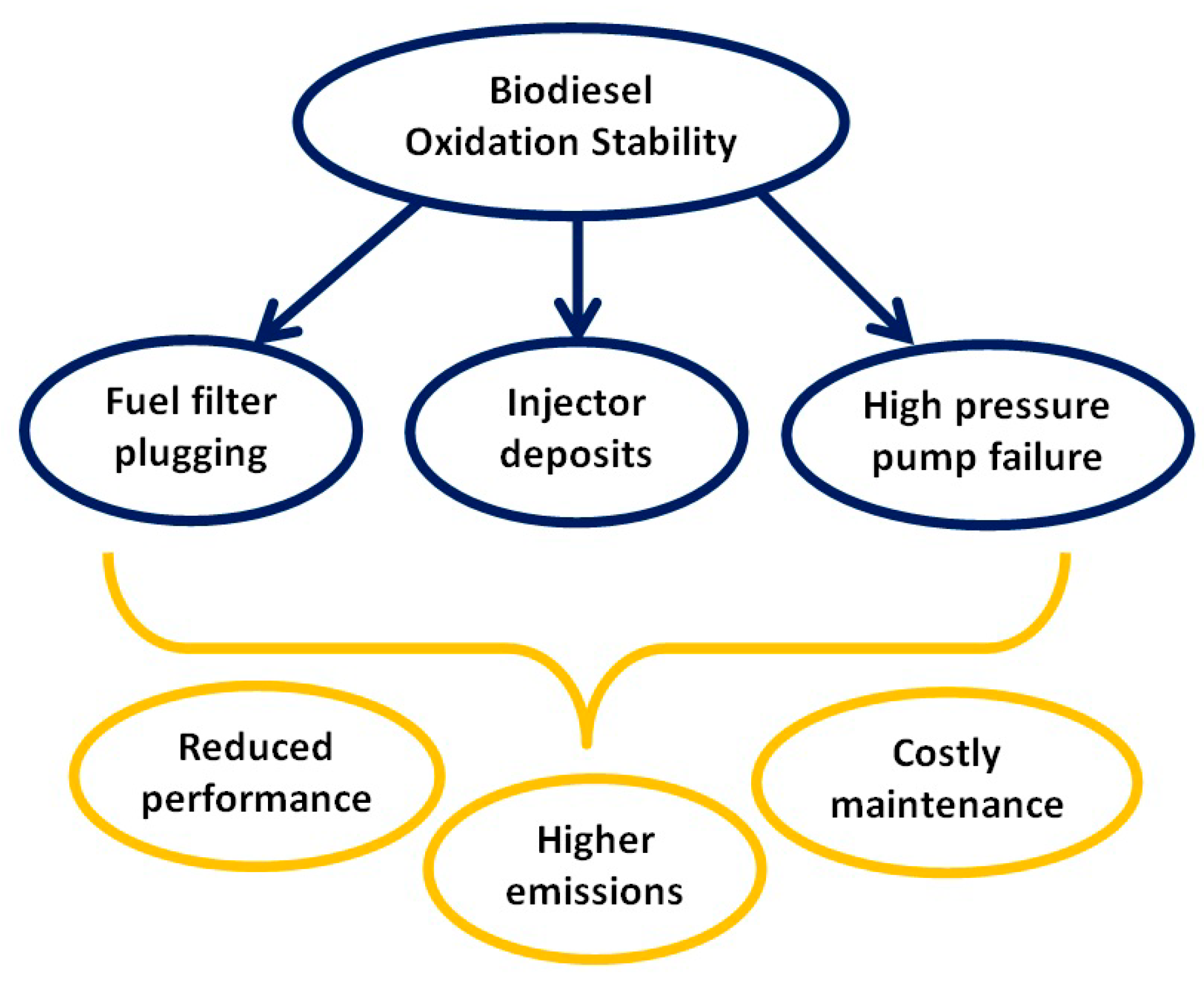
The use of high-percentage biodiesel blends is known to be associated with fuel injector deposits [11] and other types of injection system effects [12,13]. On the other hand, US and European market fuel surveys indicate that many retail biodiesel samples are out of specification, which means that poor quality biodiesel is not scarce [14,15]. The most demanding issue with the use of biodiesel is its oxidation stability, which affects performance, emissions, and engine durability (Figure 1). The more general term biodiesel degradation is referred to the modification of its original composition and properties due to aging, oxidation, and metal corrosion during the storage process [12,16].
The compatibility of seal and hose materials commonly encountered in automotive fuel systems using conventional hydrocarbon fuels has long been established and elastomer manufacturers are able to make recommendations for their use. Specialized studies [17,18] and in-use experience suggest that certain seals, gaskets, and hoses may degrade under harsh operating conditions in contact with B50 or high-percentage blends. Elastomer materials generally suffer physical or chemical changes when in contact with fuel. The extent of these changes depends on the tendency of the material to absorb fuel or on specific compounds to be dissolved or extracted. This may lead to swelling, shrinkage, embrittlement or modifications of tensile properties [19]. The extent of a physical change that can be tolerated depends on the specific application. For example, a material that swelled or softened after contact with a fuel may continue to acceptably act for a long time as a static seal. On the other hand, dynamic applications are more sensitive to swelling, due to increased friction and wear. Thus, a lower degree of volume change can be tolerated.
The requirement to produce low and ultra-low sulfur fuels for environmental reasons, is generally met by hydro-treatment. This process destroys polar nitrogen and oxygen compounds, thus leading to a deterioration of the lubricity of diesel fuel. Fuel injection system parts deterioration after using low quality fuels is reported in analogous situations in marine engines [20]. Several researchers reported that biodiesel blending at low percentages may significantly improve the lubricating properties of low sulfur diesel fuel. Moreover, the use of biodiesel blends may reduce the concentration of metallic wear particles and increase engine durability [21]. On the other hand, the associated formation of corrosive materials (organic acids, water, methanol) may affect engine life. Additionally, thermal and oxidative instability and water separation may give rise to engine operability problems. The following problems have been identified during extensive field trials: corrosion of fuel injection system parts, seal failures and low-pressure fuel line, fuel filter blockage. High-pressure fuel system problems include fuel injector holes blockage, engine oil dilution, and polymerization. Additional problems reported include pump seizures at low temperatures. Due to the above reasons, Original Equipment Manufacturers Associations are conservative regarding the use of high-percentage biodiesel blends [22,23]. Clark et al. reported no abnormal characteristics in fuel injection system tests after 200 h of operation of a John Deere 4239 TF turbocharged diesel engine fueled with methyl and ethyl soybean esters [24]. On the other hand, Fraer et al. reported higher sludge formation on the valve deck around the rocker assemblies and more injector replacement for B20 fueled engine particularly for Mack tractor engines [25]. In the same way, the National Biodiesel Board has reported that a 1000 h durability test on an engine with B20 soybean ester blend caused serious technical problems, like failure of fuel injection pump, softening of fuel system seals, and deposits on air box covers, piston components, and injectors.
Furthermore, truckers’ associations have complained that fuel filter plugging is increasing as animal fat- and soybean-based fuels are being introduced nationwide [26]. Based on the previous paragraphs, it is obvious that fuel system problems, including filter plugging by use of B100 fuel, have been mainly documented in the United States. According to a survey conducted by the Minnesota Trucking Association [27], 62% of 900 fleets said they had experienced fuel filter plugging. In most of the studies, the main problems were fuel filter plugging and injector coking.
In this study, the impact of high (B70) and medium percentage biodiesel blends (B20 and B50) on a first generation common-rail injection system and a conventional “pump-in-line” injection system, respectively was investigated. It should be mentioned that the experiments were conducted on unmodified diesel engines. The most serious failure was that of the common-rail high-pressure fuel pump and the inline pump of the single cylinder engine. These failures repeated a second time, always after the engine stayed shut down for a period of a few months each. The details of the biodiesel impact to the injection system components are presented and discussed in this paper in an effort to motivate the scientific and technical community to further investigate these effects that damage the high reliability of the diesel powertrain.
1.2. Main Types of High-Pressure Pumps for Passenger Cars.
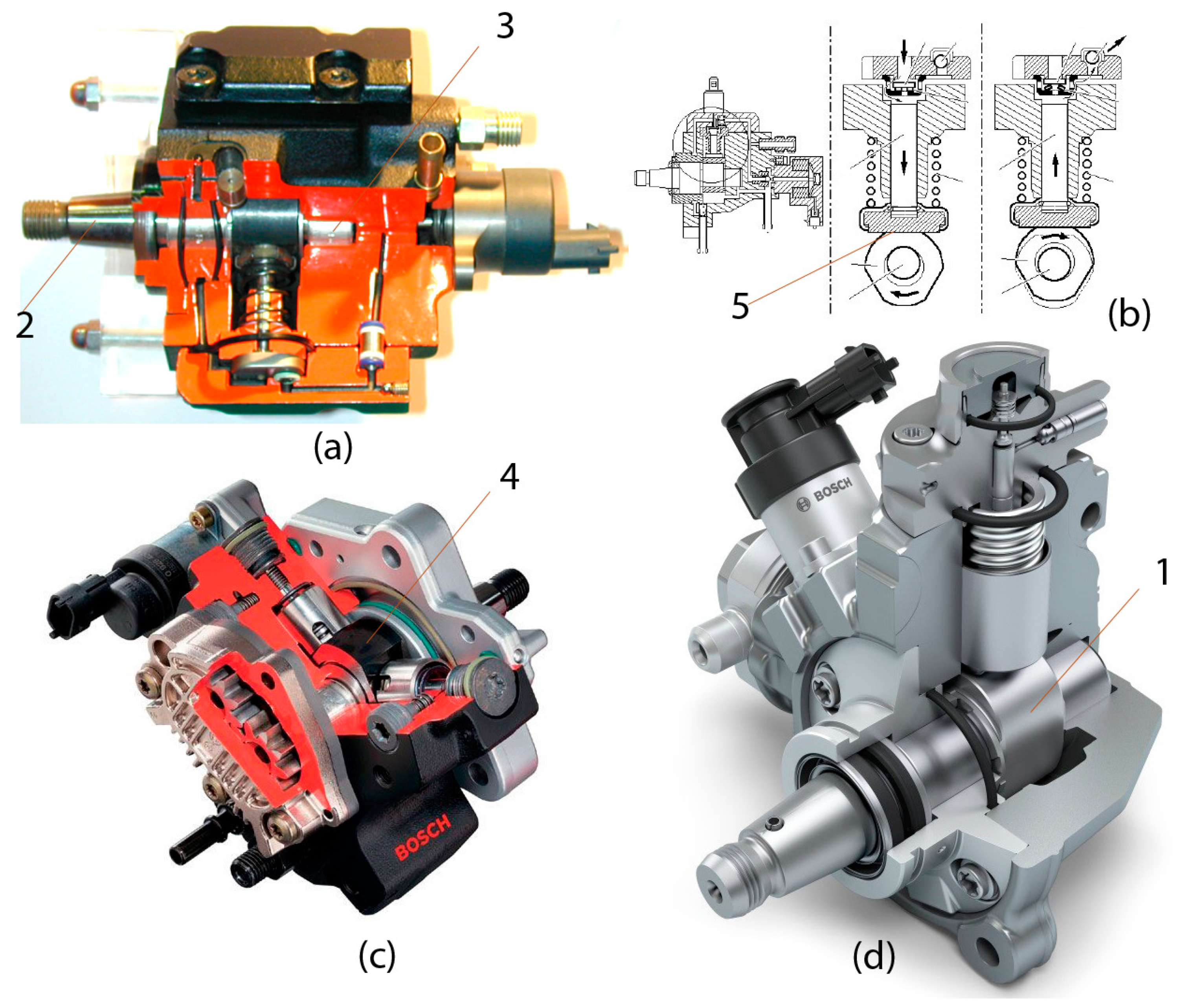
The high-pressure pump is the interface between a common-rail system’s low- and high-pressure stage. Its function is to keep the quantity of fuel required by the system ready at the necessary rail pressure level depending on the operation point [28,29,30]. The high-pressure stage of the common-rail system is divided into three sections: pressure generation, pressure storage, and fuel metering. The high-pressure assumes the function of pressure generation. Pressure storage takes place in the fuel rail to which the rail pressure sensor and the pressure-control and pressure-relief valves are fitted. The evolution of high-pressure pumps for passenger cars is presented in Figure 2.
First generation common-rail systems utilize high-pressure pumps with eccentric shaft drives and three radially-arranged plungers. There are three types of CP1 high-pressure pumps: CP1S (standard), CP1K (compact), and CP1H (reinforced). Compared to CP1K/S, CP1H is designed for higher pressures up to 1600 bar. This is achieved by reinforcing the drive mechanism, modifying the valve units, and introducing measures to increase the strength of the pump housing.
Bosch CP3 is a monoblock-housing three-plunger radial high-pressure pump with suction throttle control and an external gear pump for fuel delivery, which is flange-mounted directly on the pump. This construction of housing reduces the potential of leakage in the high-pressure section, and permits a higher delivery rate. The low-pressure ports are mainly located in the aluminum pump flange, which is bolted with the forged steel housing. This pump can withstand pressures up to 1600 bar. Unlike the CP1 pump series, the polygon’s movement is not directly transferred to the plunger but rather to the bucket tappet placed in between. This keeps the lateral forces induced by friction away from plunger and conducts them to the pump housing, improving the pump’s stability under load [28,30].
CP4 is the latest Bosch common-rail radial high-pressure pump which consists of one (CP4.1) or two (CP4.2) radial arrayed plungers and a drive shaft with a double cam, as shown in Figure 2d (1). The CP4 handles pressure levels from 1800 to 2700 bar and is used for both on-and off-highway applications from passenger cars, light- and medium-duty vehicles up to small heavy-duty vehicles. Analogous models are produced by Denso corporation, HP2, HP3, HP4 [31].
All the types of high-pressure pumps operate in the same reciprocating mode which consists of suction and delivery strokes. The working pump elements are the plunger, barrel, suction and delivery valve. The drive shaft, Figure 2a (2), is mounted in a central bearing, Figure 2a (3). The pumping elements are arranged radially with respect to the central bearing. The polygon, Figure 2c (4), is fitted to drive the shaft which forces the pump plunger, Figure 2b (5), to move up and down.
1.3. Plunger Manufacturing Process
High-pressure fuel pumps are manufactured with extremely close tolerances, especially between plunger and barrel (about 10 μm [32]). It is important to understand the manufacturing process for these parts, which is summarized below.
The fuel pump plunger pushes the fuel through a positive displacement pump by reciprocating through a chamber. This reciprocating action enables the pump to attain high-pressures.
The plunger’s pumping motion guides the fuel in the cavity from the high- to low-pressure side. The plunger first creates suction, drawing the fuel into the chamber. It then moves the opposite direction to build pressure, forcing the fuel to the discharge port.
Plunger manufacturing consists of the following phases:
- Preheating: To prepare for coating, the plunger barrel is mounted on a coating lathe. A spray gun preheats it by means of a flame. The barrel is heated to 200–220 °C, for a duration that depends on plunger’s size.
- Coating: Once the plunger reaches a prescribed temperature, a hopper loaded with a mixture of tungsten carbide powder is mounted on the gun. The gun then deposits a layer of the powder to the plunger barrel’s surface.
- Fusing: As soon as the barrel is completely coated, the powder hopper is removed. Subsequently, the plunger barrel is heated to 700–750 °C. This results in the fusion of tungsten carbide powder to the barrel’s surface. Then, the plunger is cooled at room temperature.
- Grinding: The plunger’s diameter is measured to check uniformity of coating. Then, the coated, semi-finished plunger is mounted on a CNC (computer numerical control) grinder. The surface is finished to a prescribed RMS (root mean square) roughness.
- Finishing: The plunger is checked for surface roughness, concentricity, and uniformity. If it is found to meet the specifications, it is mounted to a CNC lathe for finishing.
1.4. Elastomer Parts Compatibility
Biodiesel, a mixture of fatty acid methyl esters (FAME), is a renewable fuel produced from the homogeneous catalytic transesterification of vegetable oils, like rapeseed oil, soybean oil, and animal fats using basic hydroxides as catalysts. In a standard process of biodiesel production from rapeseed oil there are the following process steps: esterification of oil (vegetable, rapeseed, soybean, canola), separation of esterification products, methanol distillation, and purification of ester. Glycerol (glycerin) is the main formed by-product of oil esterification process. In this process, soaps and fatty acids are also created. FKM (Fluorocarbon-Based Elastomer), NBR (Nitrile Butadiene Rubber), and HNBR (Hydrogenated NBR) are also chemically compatible with both of them.
Glycerin is a by-product of the biodiesel production process and is related to amounts of unconverted or partially-converted fats and oils left from the manufacturing process. If the amount of glycerin is too high, it can lead to storage tank and fuel system filter plugging.
Table 1 summarizes the compatibility properties of various commercial elastomer parts when exposed to different types of biodiesel components, raw materials, and by-products [33], according to the manufacturers [34]. On the other hand, a review of reported effects of liquid biofuels on the deterioration of automotive rubbers [19] concluded that the physical and mechanical properties of NBR decreased after exposure to almost all the commercially-available biofuels. In regards to FKM, the main weakness of FKM rubbers towards biofuel attack was the metal oxides and hydroxides in their curing systems.
2. Materials and Methods
In this section, the specific fuel injection systems of the two engines tested, the periods and details of operation points tested, the fuels employed in the tests, the experimental apparatus for surface analysis and the cleaning and disassembly procedures applied for the injection system components are presented.
2.1. Technical Data of the Engines Studied
Two different engines were employed in the tests with high-percentage biodiesel blends in the Laboratory of Thermodynamics and Thermal Engines: (a) a PSA DW10 ATED 2.0 L, four stroke, four cylinder, turbocharged, equipped with Bosch first generation common-rail, ECU (Electronic Control Unit)-controlled injection system (Figure 3a, Table 2); and (b) a Ruggerini RF91 0.5 L, four stroke, single cylinder, naturally aspirated, equipped with a pump-in-line injection system (Figure 3b, Table 3).
2.2. Fuel Injection Systems of the Engines Studied
Bosch high-pressure pump, CP1S, can provide a 1350 bar maximum rail pressure. On the other hand, the New Diesel conventional inline pump can increase the injection pressure up to 210 bar. Technical specifications of the tested pumps, New Diesel and Bosch, are presented in Table 4 and Table 5, respectively.
2.3. Properties of Fuels Employed
The fuels under investigation were three volume-based blends of biodiesel in diesel fuel, 20%, 50%, and 70%. The tested fuels were denoted as B20, B50, and B70, respectively. Diesel fuel conforms to European standard EN 590. The biodiesel employed in the experiments was a fatty acid methyl ester produced by 40% rapeseed oil, 30% soybean oil, and 30% recycled cooking oils. It was supplied by ELIN Biofuels SA (Volos Greece) and conforms to EN14214-2012 [35]. The main specifications of the fuels are summarized in Table 6 [36,37].
High-percentage biodiesel blend, B70, was employed in the engine tests with the PSA DW10 ATED HDi (common-rail, high-pressure injection) engine. On the other hand, medium- and low-percentage biodiesel blends, B20 and B50, were employed in the engine tests with the Ruggerini RF91 DI diesel engine (low-pressure injection).
2.4. Period of Operation with Biodiesel Fuels
Both engines are regularly employed in student laboratory exercises, and also for research and development projects of the Lab. In the case of DW10, the engine was subjected to steady-state and transient testing with the B70 fuel for a total of 100 h in the period 2008–2010 (Table 7) [36,37]. The testing time was uniformly distributed among the operation points listed in Table 8. This prolonged use led to the failure of the high-pressure pump and the wear of the injector’s moving parts. After replacing with a new fuel pump and injector, the engine was regularly employed in student lab exercises with regular diesel fuel (EN590 specifications, which contains about 7% biodiesel in Greece). The lab exercises comprise short-term engine tests (typical steady-state operation points) with normal fuel, not significantly adding to engine parts deterioration. The engine was run again on-low percentage biodiesel blend (B20) for a further 50 h in 2016, in the frame of diesel filter loading and regeneration tests. After a six-month stand still of the engine, it failed to start again for the student lab testing exercises in March 2017. This time, the fuel pump was dismantled and the components were inspected for deposits, wear, and surface texture. Photographs of the components were taken in order to confirm the effect of biodiesel fuel. The results are presented in this section.
On the other hand, RF91 was subjected to steady-state testing with B20 and B50 fuels for a total of 50 and 50 h, respectively, in diesel filter loading and regeneration tests, in the period December 2011 to January 2013 (Table 7) [38,39,40]. The diesel particulate filter loading was mainly carried out at 3250 rpm and 16.2 N-m RF91 engine operation point. Regeneration of the diesel particulate filter was carried out at the 3250 rpm and 22.2 Nm engine operation point, with a total duration of about 4 h. After shut off of the engine and staying still for 4 months, it failed to start again. The mechanical pump and injector were disassembled in order to identify the cause of the failure. After cleaning and replacing of the pump on the engine, the engine was routinely employed in student laboratory exercises in the period 2014–2017. After being employed in 10 h diesel-filter loading and regeneration testing in summer 2017 (Table 7), the engine failed to start again for the student laboratory tests in 2018. Again, the pump plunger was stuck and cleaning and replacing the pump on the engine was necessary.
2.5. Cleaning and Optical Microscopy Procedure
The cleaning procedure consisted of three phases: (i) The injectors and both of the high-pressure pumps were dismantled in accordance with manufacturer technical instructions, and the metal components were thoroughly cleaned using diesel fuel in order to remove dirt and gummy deposits; (ii) In the second phase, the components were brushed using isopropanol alcohol; (iii) In the third phase, the components were put in an ultrasonic bath for 45 min. Surface analysis was performed using optical microscopy [41] at 10× magnification.
2.6. Disassembly Procedure of the Injection Systems
The common-rail injector consists of two parts: injector body and nozzle body. The most easily affected parts, besides the nozzle holes, are the injector’s moving components, like needle, plunger, and spring. An exploded view of this injector is presented in Figure 4.
An exploded view of the inline pump of the RF91 engine is shown in Figure 5. There is only one pump element (single cylinder engine) and the components are arranged inline. The most critical components of the high-pressure pump are the plunger, Figure 5a, and the barrel, Figure 5b. The plunger is driven by the pump camshaft and reset by the plunger spring, and the plunger stroke is constant. The plunger compresses fuel as it moves upward and delivers it to the nozzle.
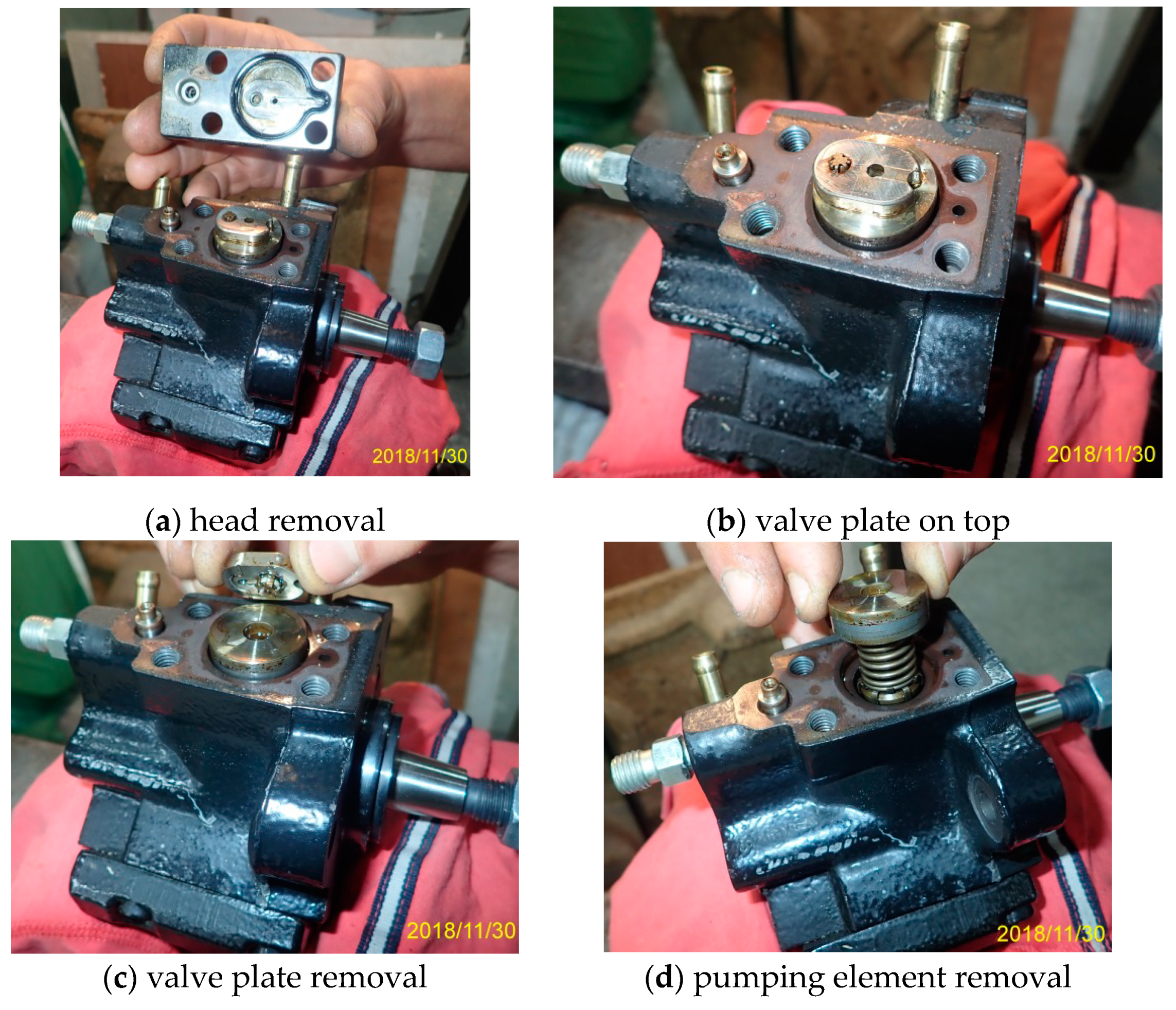
The disassembly procedure of each pumping cylinder of the CP1S pump consisted of three stages, as shown in Figure 6. At the beginning, the four overhead torx screws are removed, allowing the removal of the cast steel pump valve head, as presented in Figure 6a,b. In the second stage, as shown in Figure 6c, the steel valve plate, which includes suction and delivery valves, is removed. Finally, the pumping element is removed, which consists of plunger, barrel, and spring.
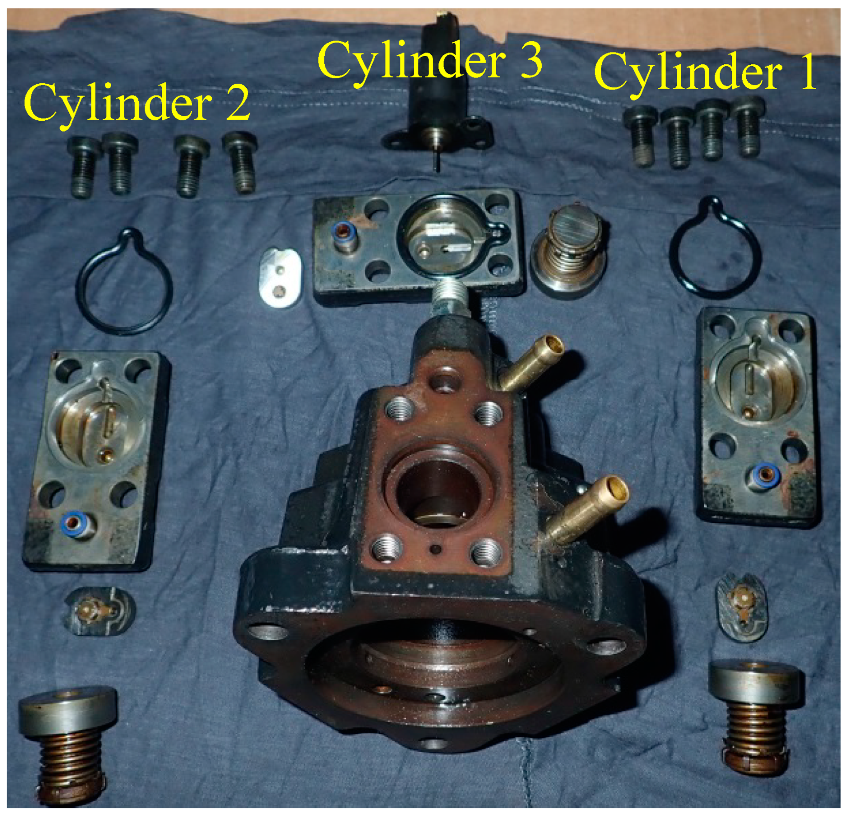
An exploded view of the dismantled pump is presented in Figure 7. The pump consists of three pumping cylinders, as described below.
3. Inspection Results and Discussion
In this section, the impact of high- and low-percentage biodiesel blends on the fuel system components’ durability, of modern and conventional diesel engines, is presented.
Biodiesel is characterized by poor oxidation stability that causes the fuel to biodegrade over time. This process is amplified due to improper storage and handling along the retail distribution chain. The results of oxidation include bacterial growth in tanks and plugging of fuel filters, injectors, and high-pressure pumps [33].
3.1. Fuel Filter Plugging
Following the fuel line, the first component of the injection system is the fuel filter, which consists of the box and the filter. Figure 8 illustrates fuel filter’s condition after 150 h operation with B70 blend. It is obvious that the filter was totally plugged by sticky slurry, causing problems in the fuel flow from the filter to the high-pressure pump. A significant quantity of brown dense slurry was also found at the bottom of the filter box. This finding is in accordance with the reported results of other researchers and associations [42].
3.2. Common-Rail Injector Wear
The next affected component of the injection system is the injectors. The effect of biodiesel fuel on the long-term durability of fuel pumps or injectors is an important subject for all biodiesel fleet users, since fuel injectors and especially high-pressure pumps are costly parts. A new set of DW10 common-rail injectors is shown in Figure 9.
On the other hand, Figure 10 presents the condition of injectors after the prolonged testing with B70 fuel. It is obvious that the nozzle body and the holes were totally covered by a dense slurry.
In order to better understand the impact of biodiesel, each injector was analyzed by means of low magnification optical microscopy. Several photos, magnification 10×, of the nozzle body, tip of the nozzle, and the nozzle holes area were taken. Figure 11 shows heavy oily deposits on the injector nozzle that disturbed the flow pattern of the injected fuel. Nozzle holes were totally covered except for the first injector, whereby the holes remained open. Based on these figures, the third and fourth injectors seem to have serious operation problems.
The next step was to disassemble and clean the injectors according to the official repair manual, as shown in Figure 4. The cleaning process included the removal of the brownish lacquer deposit via an ultrasonic bath in an aggressive detergent, at temperature of 60 °C. After the cleaning procedure, the surfaces of each part were carefully investigated for wear by means of the optical microscope. Figure 12 presents photos of the clean nozzle plungers. It was obvious that the prolonged operation with biodiesel led to further corrosion of the plungers, as indicated by the red circles.
Even though biodiesel provides better lubricity than diesel, corrosive wear and friction increase due to absorbing moisture. Biodiesel is more hygroscopic than diesel fuel and it attracts moisture, causing hydrolysis and the formation of organic acids and bacteria.
3.3. Standard Mechanical Injector Wear
Taking into account the previous findings, the same procedure was applied to the RF91 mechanical injector. Figure 13 presents a comparative view of the injector after 100 h operation with biodiesel blends. The nozzle holes area and the nozzle body were covered by oily deposits and white additive ash, influencing injection and combustion efficiency.
3.4. Common-Rail High-pressure Pump Disassembly
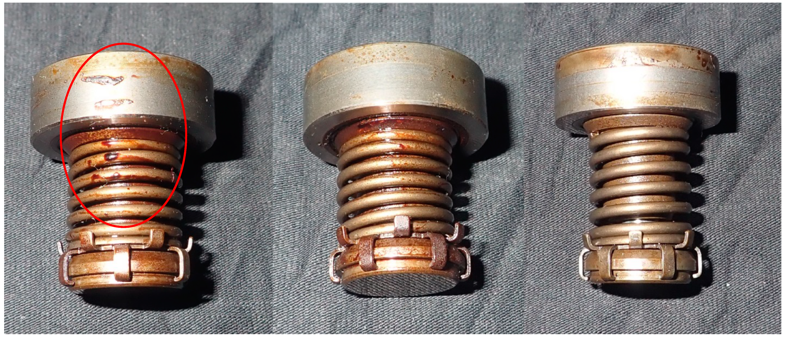
As reported above, the critical failure was that of the high-pressure pump. A summary of the diagnosis procedure is presented below. As reported in [43], in October 2010, after repeated failures to start, a thorough inspection of the fuel lines and injection system was carried out. The findings were presented above. Starting from the fuel filter, a significant quantity of dense slurry rich in fatty esters was observed. After cleaning the fuel filter, the fuel injectors were removed. The injector’s nozzle and holes were found covered by heavy, oily carbon deposits. Proceeding with disassembling the set of injectors, a certain quantity of the same oily deposit was found in the needle tip. After installing a new set of fuel injectors, the engine still could not start and the indication from the ETAS-INCA [44] interface was zero rail pressure. Inspection continued with the high-pressure fuel lines and the common-rail without any important findings. Finally, the high-pressure fuel pump was examined and it was found that all fuel was diverted to the return line. Dismantled dirty components of CP1S pump are presented in Figure 14, Figure 15, Figure 16 and Figure 17. Examination of the fuel pump parts revealed a thin brownish lacquer coating on the barrel and the internal cavities of the valve head. The lacquer was hard, dry, and could be removed by way of an ultrasonic bath. In addition, there were sticky dark brown and black particles on the barrel, spring, and valve chamber, as indicated by the red circles in Figure 14 and Figure 16, respectively.
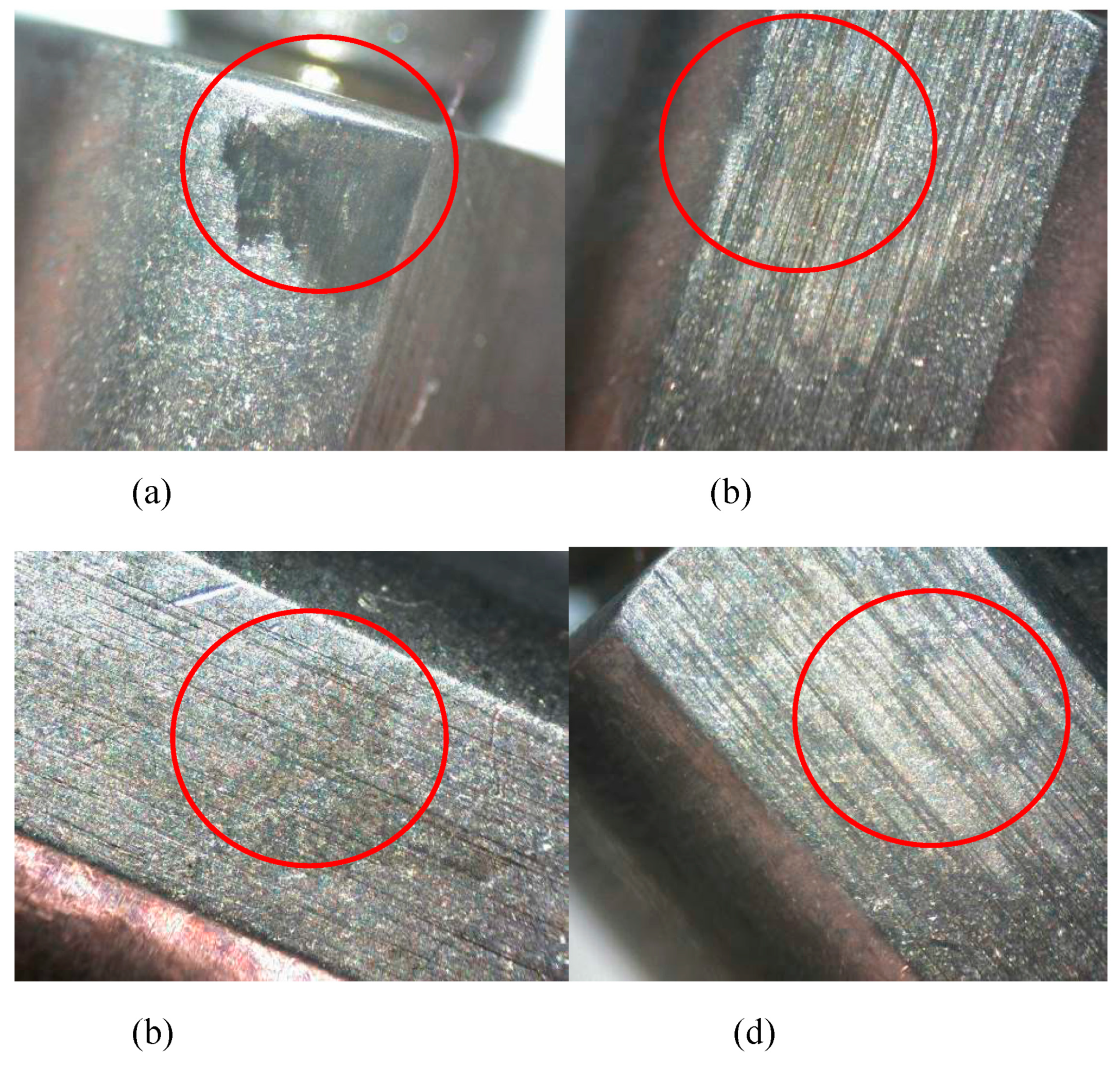
It should be noted that in this type of pump (CP1S) the plunger is not subjected to a purely axial load. Thus, a certain degree of surface wear may be present, which is enhanced by the presence of biofuel, as shown in Figure 18. The most important parameter when one deals with fuel-injection system parts is the surface roughness of the high-pressure mating components. It is important to investigate if any deterioration is present. The surface areas positioned close to the bottom of the pump plungers and to the top of barrels were examined with optical microscopy.
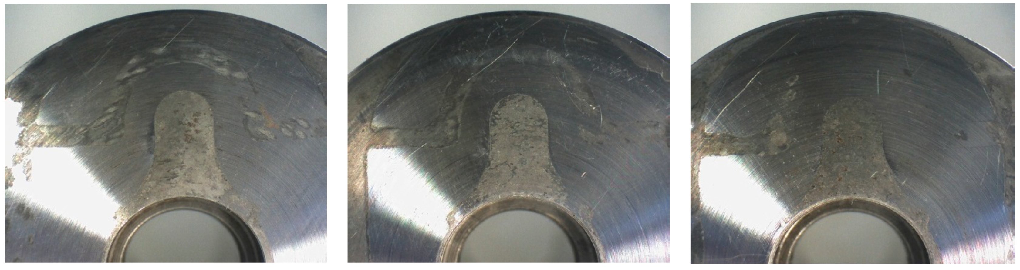
It can be clearly seen that first plunger (to the left) was found in the worst condition. Only the third one (Figure 18, right) shows the characteristic bright appearance of the chromium plating (20 μm). Furthermore, the wear on barrels was localized in the fuel flow line and appeared in the form of brown imprints that should be attributed to the corrosive behavior of biodiesel, as presented in Figure 19.
As shown in Figure 19, the first pump barrel was, again, in the worst condition in regards to surface corrosion, and the third one was in the best condition.
3.5. Gasket O-Rings and Seal Condition
After careful inspection of the pump head gaskets, delivery ports gaskets, teflon washers, camshaft housing, O-rings, and the drive shaft seal, it was concluded that no significant wear from oxidation or swelling were present, and no visible leaks were observed (Figure 20a,b).
Gaskets and O-rings are made by Nitrile and Fluorocarbon elastomer compounds, which are compatible with biodiesel. Taking into account the seal manufacturer’s technical notes [45], it becomes obvious that their sealing compound is fluorocarbon. The drive shaft seal type is indicated with red boxes. According to the specialized literature [19,46], these compounds would be expected to deteriorate after prolonged use and/or high-percentage biodiesel blends. However, in our case, no significant deterioration or swelling was observed, which is expected due to the limited hours of testing. Thus, the main damage to the pump remains the sticking of two out of the three unit-pump plungers on their barrels, close to their TDC positions, and the additional sticking of the suction and delivery valves for all three pump units.
Based on the above findings, which agree with experience from other researchers [27,47,48], it would not be wise to exploit the full range of biodiesel blending with these types of engines until the required fuel system modifications are decided by the manufacturers. A maximum blending of 20% on average would be a more conservative approach.
3.6. Standard Pump-In-Line Disassembly
The design and principle of the operation of the pump-in-line system employed in the RF91 single cylinder engine is shown in Figure 21.
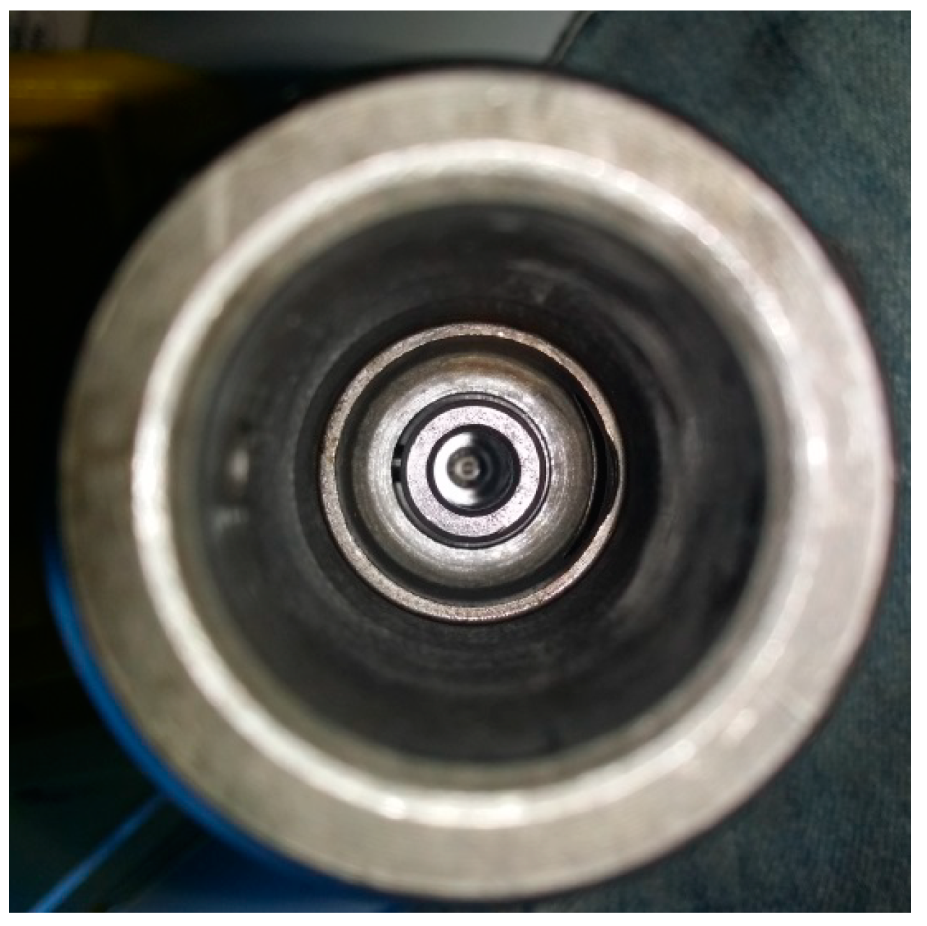
Analogous findings with the previous case were observed in the unit pump of the single cylinder engine. The pump plunger was stuck at the top dead center position (see Figure 22, view from the top, and Figure 23, right, after the dismantling of the plunger). Deposits were found also on the inside of the pump housing (Figure 23). Signs of wear were also visible on the pump cylinder (Figure 24) and the plunger’s surface (Figure 25).
As reported above, the surface quality of precision assemblies in the injection pump has a large impact on the proper operation of the engine. Both the plunger and the barrel of the pumping section are adjusted, so that the gap between the side surface of the plunger and the inner surface of the barrel is approximately 2–5 μm. This clearance provides sufficient lubrication of the side surfaces of the plunger and barrel, while still providing enough sealing to maintain the high-pressure of fuel. The penetration of slurry deposits between the surface of the plunger and the barrel can cause the sticking of the pumping elements, as was the case with the reported findings. The sticking of pumping elements was repeatedly observed after operation with high-percentage biodiesel blends and the shutdown of the engines for a period of two months or more. Moreover, this damage happened in two fuel pumps of different technologies and injection pressures.
4. Conclusions
This paper summarizes experience on the deterioration of diesel-injection equipment parts from the use of fuel blends with high-percentages of biodiesel (up to 70%) on a common-rail, high-pressure injection diesel engine and a single cylinder diesel engine.
In regards to the high-pressure fuel pump of the common-rail engine, it was found that the main mode of failure was sticking of the pump pistons near their TDC positions, due to oxidation of their sleeves at this position. The same mode of failure was found with the inline fuel pump of the single cylinder engine. This type of failure is not fatal for the pump and can be repaired by the disassembly and cleaning of the pump. However, successive repairs lead to increased wear on the plunger-cylinder surfaces, and oxidation proceeds with prolonged use of high-percentage biodiesel blends. The condition of the various gaskets and O-rings in the high-pressure pump of the common-rail system was found to be normal without any signs of deterioration. This should be expected due to the short operation time with biodiesel blends. However, this relatively short operating time, of the order of 100 h, was sufficient to cause damage to the pumps.
As a general remark, the use of biodiesel blends higher than B20 must be combined with engine- and fuel-injection system protection measures and these engines should not stay shut down for more than one month in such cases, in order to avoid sticking of the fuel pump plungers. The most probable reason that such instances are not reported in the specialized literature is that the durability tests are accelerated tests, which do not normally include large periods of intermediate engine shut down.
Author Contributions
Conceptualization, A.M.S.; Methodology, A.M.S.; D.N.T.; Investigation, D.N.T.; Resources, A.M.S.; D.N.T.; Writing—Original Draft Preparation, D.N.T.; Writing—Review & Editing, A.M.S.; Visualization, D.N.T.; Supervision, A.M.S.; Project Administration, D.N.T.
Funding
This research received no external funding.
Acknowledgments
The authors would like to thank their former Mechanical Engineering students Nikos Sakalidis and Manos Papadopetrakis for their assistance in the tests and disassembly of the RF91 engine, in the frame of their Diploma Thesis in the Laboratory of Thermodynamics and Thermal Engines, University of Thessaly. Additionally, special thanks are due to personnel from the company Sielman SA, Volos Greece, for their assistance with the disassembly and photographing of the Bosch CP1S common-rail fuel pump.
Conflicts of Interest
The authors declare no conflict of interest.
References
- DieselNet. Biodiesel—Mono Alkyl Esters. In DieselNet Technology Guide » Alternative Diesel Fuels; Revision 2007.07. Available online: www.dieselnet.com (accessed on 21 March 2016).
- Giakoumis, E.G.; Rakopoulos, C.D.; Dimaratos, A.M.; Rakopoulos, D.C. Exhaust emissions of diesel engines operating under transient conditions with biodiesel fuel blends. Prog. Energy Combust. Sci. 2012, 38, 691–715. [Google Scholar] [CrossRef]
- Agarwal, A.K. Biofuels (alcohols and biodiesel) applications as fuels for internal combustion engines. Prog. Energy Combust. Sci. 2007, 33, 233–271. [Google Scholar] [CrossRef]
- Niculescu, R.A.; Clenci, A.; Iorga-Siman, V. Review on the use of diesel–Biodiesel–Alcohol blends in compression ignition engines. Energies 2019, 12, 1194. [Google Scholar] [CrossRef]
- ASTM D 6751-18—Standard Specification For Biodiesel (B100) Blend Stock For Distillate Fuels; ASTM: West Conshohocken, PA, USA, 2018.
- ASTM D7467-18a—Standard Specification for Diesel Fuel Oil, Biodiesel Blend (B6 to B20); ASTM: West Conshohocken, PA, USA, 2018.
- Kline, K.L.; Oladosu, G.A.; Wolfe, A.K.; Perlack, R.D.; Dale, V.H. Biofuel Feedstock Assessment for Selected Countries; O.R.N. LABORATORY: Oak Ridge, TN, USA, 2008. [Google Scholar]
- Al-Riffai, P.; Dimaranan, B.; Laborde, D. Global Trade and Environmental Impact Study of the EU Biofuels Mandate; IFPRI: Washington, DC, USA, 2010. [Google Scholar]
- Tsoutsos, T. Quality characteristics of biodiesel produced from used cooking oil in southern Europe. ChemEngineering 2019, 3, 19. [Google Scholar] [CrossRef]
- EU. Automotive Fuels—Fatty Acid Methylesters (FAME) for Diesel Engines—Requirements and Test Methods; EN 14214:2012; EU: Brussels, Belgium, 2012. [Google Scholar]
- Birgel, A.; Ladommatos, N.; Aleiferis, P.; Zülch, S.; Milovanovic, N.; Lafon, V.; Orlovic, A.; Lacey, P.; Richards, P. Deposit Formation in the Holes of Diesel Injector Nozzles: A Critical Review; SAE International: Warrendale, PA, USA, 2008. [Google Scholar]
- Gopalan, K.; Chuck, C.J.; Roy-Smith, C.; Bannister, C.D. Assessing the Impact of FAME and Diesel Fuel Composition on Stability and Vehicle Filter Blocking; SAE Technical Papers; SAE International: Warrendale, PA, USA, 2019. [Google Scholar]
- Terry, B.; McCormick, R.L.; Natarajan, M. Impact of Biodiesel Blends on Fuel System Component Durability; SAE International: Warrendale, PA, USA, 2006. [Google Scholar]
- Lopes, S.M.; Cushing, T. The Influence of Biodiesel Fuel Quality on Modern Diesel Vehicle Performance; SAE International: Warrendale, PA, USA, 2012. [Google Scholar]
- Fortunato, M.A.; Lenglet, F.; Amara, A.B.; Starck, L. Are Internal Diesel Injector Deposits (IDID) Mainly Linked to Biofuel Chemical Composition or/and Engine Operation Condition? SAE Technical Papers; SAE International: Warrendale, PA, USA, 2019. [Google Scholar]
- Agarwal, S.; Singhal, S.; Singh, M.; Arora, S.; Tanwer, M. Role of antioxidants in enhancing oxidation stability of biodiesels. ACS Sustain. Chem. Eng. 2018, 6, 11036–11049. [Google Scholar] [CrossRef]
- Xue, J.; Grift, T.E.; Hansen, A.C. Effect of biodiesel on engine performance and emission. Renew. Sustain. Energy Rev. 2011, 15, 1098–1116. [Google Scholar] [CrossRef]
- Fazal, M.A.; Haseed, A.S.M.A.; Masjuki, H.H. Biodiesel feasibility study: An. evaluation of material compatibility; performance; emission and engine durability. Renew. Sustain. Energy Rev. 2011, 15, 1314–1324. [Google Scholar] [CrossRef]
- Akhlaghi, S.; Gedde, U.W.; Hedenqvist, M.S.; Braña, M.T.C.; Bellander, M. Deterioration of automotive rubbers in liquid biofuels: A review. Renew. Sustain. Energy Rev. 2015, 43, 1238–1248. [Google Scholar] [CrossRef]
- Bejger, A.; Chybowski, L.; Gawdzińska, K. Utilising elastic waves of acoustic emission to assess the condition of spray nozzles in a marine diesel engine. J. Mar. Eng. Technol. 2018, 17, 153–159. [Google Scholar] [CrossRef]
- Agarwal, A.K.; Bijwe, J.; Das, L.M. Wear assessment in a biodiesel fuelled compresion ignition engine. ASME J. Eng. Gas Turbines Power 2003, 125, 820–826. [Google Scholar] [CrossRef]
- FIE. Fuel Requirements for Diesel Fuel Injection Systems Diesel Fuel Injection Equipment Manufacturers Common Position Statement; FIE: West Conshohocken, PA, USA, 2009. [Google Scholar]
- FIE. Diesel Fuel Injection Equipment Manufacturers Common Position Statement: FAME Fuels as a Replacement or Extender for Diesel Fuels; FIE: West Conshohocken, PA, USA, 2004. [Google Scholar]
- Clark, S.J.; Wagner, L.; Schrock, M.D.; Piennaar, P.G. Methyl and esthyl soybean esters as renewable fuels for diesel engines. J. Am. Oil Chem. Soc. 1984, 61, 1632–1643. [Google Scholar] [CrossRef]
- Fraer, R.; Dinh, H.; McCormick, R.L.; Chandler, K.; Buchholz, B. Operating Experience And Teardown Analysis For Engines Operateed On Biodiesel Blends (B20); SAE 2005-01-3641; SAE International: Warrendale, PA, USA, 2005. [Google Scholar]
- Rakopoulos, D.C.; Rakopoulos, C.D.; Giakoumis, E.G.; Papagiannakis, R.G.; Kyritsis, D.C. Influence of properties of various common bio-fuels on the combustion and emission characteristics of high-speed DI (direct injection) diesel engine: Vegetable oil, bio-diesel, ethanol, n-butanol, diethyl ether. Energy 2014, 73, 354–366. [Google Scholar] [CrossRef]
- Truckers complain that biodiesel fuel is clogging engine filters. PTSA Weekly Update. 2005, p. 7. Available online: http://209.157.64.200/focus/f-news/1554217/posts (accessed on 21 March 2019).
- Mollenhauer, K.; Tschoeke, H. Handbook of Diesel Engines; Springer: Berlin, Germany, 2010. [Google Scholar]
- Van Basshuysen, R.; Schaefer, F. Internal Combustion Engine Handbook—Basics, Components, Systems, Perspectives; SAE Siemens VDO, SAE International: Warrendale, PA, USA, 2004. [Google Scholar]
- Reif, K. Diesel Engine Management Systems and Components; Springer Vieweg: Berlin, Germany, 2014. [Google Scholar]
- Denso. Common-rail Components. 2019. Available online: https://www.denso-am.com/ (accessed on 21 March 2019).
- Reif, K. Dieselmotor-Management: Systeme, Komponenten, Steuerung und Regelung; Springer Vieweg: Berlin, Germany, 2012. [Google Scholar]
- Hoekman, S.K.; Broch, A.; Robbins, C.; Ceniceros, E.; Natarajan, M. Review of biodiesel composition, properties, and specifications. Renew. Sustain. Energy Rev. 2012, 16, 143–169. [Google Scholar] [CrossRef]
- Trelleborg_Sealing_Solutions. O-Rings, Your Partner for Sealing Technology, 7th ed.; Trelleborg_Sealing_Solutions: Trelleborg, Sweden, 2007. [Google Scholar]
- EU. Fatty Acid Methyl Esters (FAME) for Diesel Engines—Requirements and Test Methods; EN-14214; EU: Brussels, Belgium, 2003. [Google Scholar]
- Tziourtzioumis, D. Experimental investigation of the effect of a B70 biodiesel blend on a common-rail, passenger car Diesel engine. Inst. Mech. Eng. (Part D J. Automob. Eng.) 2009, 223, 685–701. [Google Scholar] [CrossRef]
- Tziourtzioumis, D.; Stamatelos, A. Effects of a 70% biodiesel blend on the fuel injection system operation during steady-state and transient performance of a common-rail diesel engine. Energy Convers. Manag. 2012, 60, 56–67. [Google Scholar] [CrossRef]
- Tziourtzioumis, D.N.; Stamatelos, A.M. Investigation of the effect of biodiesel blends on the performance of a fuel additive-assisted diesel filter system. Int. J. Eng. Res. 2014, 15, 406–420. [Google Scholar] [CrossRef]
- Tziourtzioumis, D.N.; Stamatelos, A.M. Experimental investigation of the effect of biodiesel blends on a DI diesel engine’s injection and combustion. Energies 2017, 10, 970. [Google Scholar] [CrossRef]
- Tziourtzioumis, D.N.; Stamatelos, A.M. Effects of B20 on the operation of a single-cylinder engine equipped with a SiC diesel particulate filter. J. Energy Eng. 2014, 140, A4014009. [Google Scholar] [CrossRef]
- Supra Foto Elektronik Vertriebs GmbH. Traveler USB Mikroskop, Gebrauchsanweisung, 7th ed.; Supra Foto Elektronik Vertriebs GmbH: Kaiserslautern, Germany, 2008. [Google Scholar]
- IntelliStick, I. 2008. Available online: www.intellistick.com (accessed on 20 February 2015).
- Tziourtzioumis, D.N. Experimental Investigation of the Steady State and Transient Operation of Diesel Engines Fueled by High-Percentage Biodiesel Blends. Ph.D. Thesis, University of Thessaly, Volos, Greece, June 2012. [Google Scholar]
- ETAS. INCA Tools for Measurement, ECU Calibration, and Diagnostics; ETAS: Stuttgart, Germany, 2018; Available online: https://www.etas.com/en/products/inca_software_products.php (accessed on 21 March 2019).
- Kaco. Radial Shaft Seals and Systems: Seals for Diesel Pumps. 2019. Available online: https://www.kaco.de/en/products/radial-shaft-sealing-rings-and-systems/seals-for-diesel-pumps/ (accessed on 21 March 2019).
- Haseeb, A.S.M.A.; Jun, T.S.; Fazal, M.A.; Masjuki, H.H. Degradation of physical properties of different elastomers upon exposure to palm biodiesel. Energy 2011, 36, 1814–1819. [Google Scholar] [CrossRef]
- Clogging Triggers Suspension, Minnesota Halts 2% Biodiesel Requirement Through Jan 13. The Oil Spot News by DTN; DTN: Burnsville MN, USA, 2005.
- Okamoto, B. Biodiesel Fleet Durability Study. July 2010. California Air Resources Board. Available online: https://www.arb.ca.gov/fuels/diesel/altdiesel/biodieseldurabilityreport2010_08_11.pdf (accessed on 21 March 2019).
Figure 1.
Effects of biodiesel oxidation stability problems on engine operation.

Figure 2.
Comparative cross-section views of the different pump generations: CP1 (a,b), CP3 (c), CP4 (d).
Figure 2.
Comparative cross-section views of the different pump generations: CP1 (a,b), CP3 (c), CP4 (d).

Figure 3.
Engine test beds: (a) PSA DW10 ATED, (b) Ruggerini RF91.

Figure 4.
Common-rail injector components. From right to left: (a) Injector body including supply and return fuel line, (b) spring, (c) plunger and nozzle body including (d) needle, (e) nozzle house, and (f) washer.
Figure 4.
Common-rail injector components. From right to left: (a) Injector body including supply and return fuel line, (b) spring, (c) plunger and nozzle body including (d) needle, (e) nozzle house, and (f) washer.

Figure 5.
Exploded view of New Diesel pump. (a) plunger; (b) barrel.

Figure 6.
Disassembly steps of the common-rail high-pressure pump: removal of head, valve plate, and pumping element.
Figure 6.
Disassembly steps of the common-rail high-pressure pump: removal of head, valve plate, and pumping element.

Figure 7.
Disassembly view of the Bosch CP1S high-pressure pump, showing components assessed for wear.
Figure 7.
Disassembly view of the Bosch CP1S high-pressure pump, showing components assessed for wear.

Figure 8.
Fuel filter holder (left) and the filter cartridge (right) of the DW10 engine after 100 h operation with B70 and 50 h operation with B20 (see Table 7).
Figure 8.
Fuel filter holder (left) and the filter cartridge (right) of the DW10 engine after 100 h operation with B70 and 50 h operation with B20 (see Table 7).

Figure 9.
New set of common-rail injectors (left) and injector nozzle (right).

Figure 10.
Used common-rail injectors (left) and closer view of the deposits (right).

Figure 11.
Common-rail injectors magnified view (10×) after 100 h operation with B70 fuel.

Figure 12.
Magnified view (10×) of the injector plungers.

Figure 13.
RF91 nozzle tip magnified (a) after 100 h operation with B20 and B50, including 50 ppm cerium-doped fuel additive; and (b) after ultrasonic cleaning.
Figure 13.
RF91 nozzle tip magnified (a) after 100 h operation with B20 and B50, including 50 ppm cerium-doped fuel additive; and (b) after ultrasonic cleaning.

Figure 14.
Pumping elements of the CP1S pump cylinders (barrel, plunger, spring). Two out of the three elements were stuck in the Top Dead Center position (end of delivery stroke).
Figure 14.
Pumping elements of the CP1S pump cylinders (barrel, plunger, spring). Two out of the three elements were stuck in the Top Dead Center position (end of delivery stroke).

Figure 15.
Top view of pumping elements covered by gummy deposits.

Figure 16.
Affected valve heads. Black sticky particles were observed in two of them.

Figure 17.
High-pressure delivery tube (a) and delivery valve (b) of the third cylinder, which were totally covered by sticky deposits.
Figure 17.
High-pressure delivery tube (a) and delivery valve (b) of the third cylinder, which were totally covered by sticky deposits.

Figure 18.
Magnified view (10×) of the clean pump plungers.

Figure 19.
Magnified top view (10×) of the clean pump barrels.

Figure 20.
Elastomer parts of CP1S pump (gaskets, O-rings, washers, and seal). (a) pump gaskets and o-rings; (b) pump drive shaft seal; (c) materials employed in diesel fuel pump shaft seals [44].
Figure 20.
Elastomer parts of CP1S pump (gaskets, O-rings, washers, and seal). (a) pump gaskets and o-rings; (b) pump drive shaft seal; (c) materials employed in diesel fuel pump shaft seals [44].

Figure 21.
Design and functional principle of the inline pump injection system.

Figure 22.
Closer view of the New Diesel pump’s stuck plunger.

Figure 23.
Inside view of the pump housing. Gummy deposits are present.

Figure 24.
Details of wear on the pump cylinder.

Figure 25.
Details of wear on the plunger.


Table 1.
Elastomer materials compatibility with different types of biodiesel raw materials, components, and by-products.
Table 1.
Elastomer materials compatibility with different types of biodiesel raw materials, components, and by-products.
| Raw Materials, Biodiesel Components, and By-Products | Nitrile Butadiene Rubber (NBR) | HNBR (Hydrogenated NBR) | Fluorocarbon-Based Elastomer (FKM) |
|---|---|---|---|
| Rapeseed oil | good * | good * | very good ** |
| Soybean oil | very good | very good | very good |
| Animal fats | very good | very good | very good |
| Animal oil | very good | very good | very good |
| Vegetable oil | very good | very good | very good |
| Glycerin (glycerol) | very good | very good | very good |
| Soaps | very good | very good | very good |
| Fatty acids | good | good | very good |
* Good suitability: Some effects from exposure with some loss of physical properties. Some chemical swelling. ** Very good suitability: Elastomer shows little or no effect from exposure. Little effect on performance and physical properties. Very good resistance. [34].
Table 2.
PSA DW10 ATED engine specifications.
| Engine Type | HSDI Turbocharged Diesel Engine |
|---|---|
| Number of cylinders | 4 in line |
| Bore × stroke | 85 × 88 mm |
| Rated power | 80 kW, 4000 rpm |
| Rated torque | 250 Nm, 2000 rpm |
| Compression ratio | 18:1 |
| Electronic control unit version | Bosch EDC 15C2 HDI |
Table 3.
Ruggerini RF91 engine specifications.
| Engine Type | DI 4-Stroke Naturally-Aspirated Diesel Engine |
|---|---|
| Number of cylinders | 1 |
| Bore × stroke | 90 × 75 mm |
| Rated power | 8.1 kW, 3600 rpm |
| Rated torque | 25 Nm, 2500 rpm |
| Compression ratio | 18.5:1 |
Table 4.
PSA DW10 ATED injection system specifications.
| Fuel Injection Pump Type | Bosch, CP1S3/R65/10-16S, OEM PN: 0 445 010 010 |
|---|---|
| Pump displacement | 0.69 cc/rev |
| Architecture | 3-plunger |
| Pump plunger diameter | 6.5 mm |
| Nominal max pressure | 1350 bar |
| Injectors type | Bosch 0445110076 |
| Number/diameter of nozzle holes | 5 × 0.123 mm |
Table 5.
Ruggerini RF91engine injection system specifications.
| Fuel Injection Pump Type | New Diesel, OEM PN: NPFR 1K60-1685 |
|---|---|
| Injector needle diameter | 4 mm |
| Number/diameter of nozzle holes | 4 × 0.24 mm |
| Nozzle hole length | 0.6 mm |
| Pin height | 0.125–0.175 mm |
| Sump volume | 0.36 mm3 |
| Injector opening pressure | 210 bar |
| Pump plunger diameter | 7 mm |
Table 6.
Comparison of the main fuel properties, between biodiesel and diesel fuel.
| Specifications/Ranges | Biodiesel (FAME) | Diesel |
|---|---|---|
| Density (15 °C) [kg/m3] | 865 | 825 |
| Viscosity (40 °C) [cSt] | 4.7 | 2.5 |
| Cetane number | 55 | 50 |
| Cold filter plugging point [°C] | −3 | −12 |
| Gross heating value [MJ/kg] (measured) | 40.3 | 46.1 |
| Lower heating value [MJ/kg] (calculated) | 37.7 | 43.3 |
| Water content [mg/kg] | 330 | - |
| Acid number [mg KOH/g] | 0.16 | - |
| Sulfur content [ppm] | - | 50 |
| Iodine number g iodine/100 g | 117 | - |
Table 7.
Use of the two engines in tests and experiments in the period 2008–2017.
| Year | DW10 Engine Tests | Duration | DW10 Engine Tests | Duration | RF91 Engine Tests | Duration | RF91 Engine Tests | Duration |
|---|---|---|---|---|---|---|---|---|
| 2008–2009 | Engine cycles w. B70 vs B0 | 55 h | Laboratory exercises (students) | 5 h | - | - | Laboratory exercises (students) | 2 h |
| 2009–2010 | Engine cycles w. B70 | 35 h | Laboratory exercises (students) | 5 h | - | - | Laboratory exercises (students) | 2 h |
| 2010–2011 | - | - | Laboratory exercises (students) | 2 h | - | - | Laboratory exercises (students) | 2 h |
| 2011–2012 | - | - | Laboratory exercises (students) | 2 h | Diesel Particulate filter loading B20–50 | 50 h | Laboratory exercises (students) | 2 h |
| 2012–2013 | - | - | Laboratory exercises (students) | 2 h | Diesel Particulate filter loading B20–50 | 50 h | Laboratory exercises (students) | 2 h |
| 2013–2014 | - | - | Laboratory exercises (students) | 2 h | - | - | Laboratory exercises (students) | 2 h |
| 2014–2015 | - | - | Laboratory exercises (students) | 2 h | - | - | Laboratory exercises (students) | 2 h |
| 2015–2016 | Diesel filter loading B20 | 50 h | Laboratory exercises (students) | 2 h | - | - | Laboratory exercises (students) | 2 h |
| 2016–2017 | - | - | Laboratory exercises (students) | - | Diesel Particulate filter loading B20 | 10 h | Laboratory exercises (students) | 4 h |
Table 8.
DW10 engine operation points tested with B70 fuel (see Table 7).
Table 8.
DW10 engine operation points tested with B70 fuel (see Table 7).
| Engine Speed [rpm] | 900 | 1260 | 1500 | 1760 | 2020 | 2400 | 2520 | 2800 |
|---|---|---|---|---|---|---|---|---|
| bmep [bar] | 0 | 0.8 | 6.7 | 2.3 | 9.3 | 11.5 | 4.5 | 13.7 |
| bmep [bar] | 2.3 | 9.3 | 4.5 | 11.5 | 13.7 | 6.7 | 15.1 |
© 2019 by the authors. Licensee MDPI, Basel, Switzerland. This article is an open access article distributed under the terms and conditions of the Creative Commons Attribution (CC BY) license (http://creativecommons.org/licenses/by/4.0/).
Share and Cite
MDPI and ACS Style
Tziourtzioumis, D.N.; Stamatelos, A.M. Diesel-Injection Equipment Parts Deterioration after Prolonged Use of Biodiesel. Energies 2019, 12, 1953. https://doi.org/10.3390/en12101953
AMA Style
Tziourtzioumis DN, Stamatelos AM. Diesel-Injection Equipment Parts Deterioration after Prolonged Use of Biodiesel. Energies. 2019; 12(10):1953. https://doi.org/10.3390/en12101953
Chicago/Turabian StyleTziourtzioumis, Dimitrios N., and Anastassios M. Stamatelos. 2019. "Diesel-Injection Equipment Parts Deterioration after Prolonged Use of Biodiesel" Energies 12, no. 10: 1953. https://doi.org/10.3390/en12101953
Note that from the first issue of 2016, this journal uses article numbers instead of page numbers. See further details here.