Innovative Design of Drone Landing Gear Used as a Receiving Coil in Wireless Charging Application


1
Department of Industrial and Information Engineering and Economics, University of L’Aquila, 67100 L’Aquila, Italy
2
Department of Astronautics, Electrical and Energetics Engineering, Sapienza University of Rome, 00185 Rome, Italy
*
Author to whom correspondence should be addressed.
Energies 2019, 12(18), 3483; https://doi.org/10.3390/en12183483
Submission received: 2 August 2019
/
Revised: 29 August 2019
/
Accepted: 3 September 2019
/
Published: 10 September 2019
(This article belongs to the Special Issue Intelligent Wireless Power Transfer System and Its Application)
Abstract
:A near-field wireless power transfer (WPT) technology is applied to recharge the battery of a small size drone. The WPT technology is an extremely attractive solution to build an autonomous base station where the drone can land to wirelessly charge the battery without any human intervention. The innovative WPT design is based on the use of a mechanical part of the drone, i.e., landing gear, as a portion of the electrical circuit, i.e., onboard secondary coil. To this aim, the landing gear is made with an adequately shaped aluminum pipe that, after suitable modifications, performs both structural and electrical functions. The proposed innovative solution has a very small impact on the drone aerodynamics and the additional weight onboard the drone is very limited. Once the design of the secondary coil has been defined, the configuration of the WPT primary coil mounted in a ground base station is optimized to get a good electrical performance, i.e., high values of transferred power and efficiency. The WPT design guidelines of primary and secondary coils are given. Finally, a demonstrator of the WPT system for a lightweight drone is designed, built, and tested.
1. Introduction
The use of unmanned aerial vehicles (UAVs) is becoming more and more popular in various areas of application, such as surveillance, monitoring, and couriers [1,2]. The popular lightweight drones are equipped with several (generally four or six) electric motors (rotors) powered by a lithium battery that permits a flight time of about 20–40 min [3,4]. This time can be too short for some missions and this can be a limitation in the drone usage. To increase the operational time, it is possible to equip the drone with a higher capacity battery, but this inevitably leads to a greater weight with a consequent reduction of the payload. Alternatively, the mission time can be prolonged by rapidly replacing or charging the battery. Currently, this operation requires a human intervention, but the future goal is to make the drone completely autonomous. This objective can be reached by designing a ground base station where, after drone landing, the batteries can be automatically exchanged [5] or quickly recharged. The first solution can be very expensive and complex due to the presence of many robotized mechanisms. Thus, the main interest is in autonomous battery recharge without using complex mechanical elements or any human intervention. This can be easily done by using the inductive near-field wireless power transfer (WPT) technology that allows a very efficient and reliable power transmission between the ground base station and the drone [6,7,8,9,10,11,12,13]. The application of this technology to drone battery charging must take into account several aspects, mainly related to the additional weight onboard the drone, that must be limited as much as possible. Another critical aspect is the misalignment of the WPT coils due to an imprecise landing of the drone that can lead to a reduction of the coupling factor between coils, and therefore of the electrical performance. These two aspects have been investigated in the recent past, and several solutions have been presented [14,15,16,17,18,19,20,21,22,23,24,25,26,27,28,29]. All the proposed solutions were mainly derived by previous WPT applications in other fields such as automotive or consumer electronics, and the main focus was on adapting these techniques to drones. Here, a completely innovative solution is proposed. The major issues to recharge drone batteries by WPT systems are described in several past works [14,15,16,17,18,19]. In [15], a simple charging system is realized using two circular planar spiral coils, the transmitting one placed on the charging pad and the receiving one on-board the drone. The main disadvantage of this configuration is the reduction of the operative payload due to the extra weight of the coil. In [16], the attention is focused on a landing procedure aimed to improve the landing precision in order to reduce the misalignment between the transmitting and receiving coils. Another solution to avoid the coil misalignment is proposed in [17], adopting an automatic system to align the primary coil with the on-board secondary coil after landing, but this solution might not be very reliable due to the presence of movable parts. In [14], a miniaturized receiving coil is placed on the landing leg of a drone, and an array of primary coils is adopted to improve the performances of the system. A charging system based on radio frequency (RF) transmission is presented in [18] and [22], while the capacitive WPT system is adopted in [19]. The main disadvantages of the RF system is the compliance with electromagnetic compatibility (EMC)/electromagnetic interference (EMI) regulations, while the maximum output power and the low efficiency is the main limitation of capacitive technology.
Traditionally, the inductive near-field WPT is based on the use of two coupled coils, the primary placed on the ground base station and the secondary installed on-board the drone. The widely popular coils, without using ferrite (this material should be avoided in drone application for the weight reduction), have the following characteristics: Multi-turn planar coils, mainly made of copper, often using a Litz wire. Obviously, the secondary coil in copper must be installed on-board the drone, as well as the secondary electrical circuit, for the capacitance compensation and some electronics for control and communication. All this material leads to additional weight of the drone that can significantly reduce the payload, especially for lightweight drones, and/or the flight time. To avoid the additional weight, an innovative original solution of the secondary coil design is here proposed. The main idea is to use a structural element of the drone as a secondary coil, without adding any new coil [30]. In all past works, the receiving system is a separate part that it is added to the drone, while with the proposed configuration the receiving coil is integrated in a pre-existent part of the drone. This makes possible to use the drone landing gear with a suitable (closed) shape as a single-turn secondary coil. Obviously, the landing gear must be realized in a light, highly conductive material and must have low AC impedance at the WPT operational frequency that is usually in the range 150 kHz–13.56 MHz. The configuration that perfectly meets the required electrical and mechanical characteristics is an aluminum pipe that is therefore adopted for the drone landing gear in the proposed experimental work. As a consequence of the use of the metallic landing gear as a secondary coil, the overall design of the WPT system must be adequately revisited. In fact, the typical landing gear has a three-dimensional (3D) configuration, with the main function to separate the drone from the ground, and it cannot be modeled as a planar coil. Furthermore, it is composed by only one turn, thus the WPT performance could be limited. The landing gear made of aluminum pipe must be adequately dimensioned (shape, diameter, and thickness) to obtain the required mechanical characteristics and to correctly operate as a secondary coil at the WPT operational frequency. Finally, the primary coil must be well designed to achieve good electrical performance also in the case of imperfect landing. All these aspects are discussed in the following sections. First, the design of the landing gear is presented and discussed, then the optimization of the primary coil is performed with the goal to improve the system efficiency. Finally, the obtained simulation results are validated by measurements in a WPT system demonstrator mounted in a commercial lightweight drone.
2. WPT Design
2.1. System Configuration
The application of the WPT technology to drones permits the realization of automatic base stations where drones can automatically land and recharge the battery. Unlike other applications, the design process of a WPT system for a drone must take care of some specifics aspects. First of all, the on-board components for the wireless charging must be as light as possible to avoid a reduction of the overall payload and/or of the flight time. The electrical components must not interfere with the viewing area of the drone payload, as described in [14]. From an electric point of view, drones are generally powered by ultra-high-density lithium batteries, and a very relevant amount of power is necessary to permit fast battery charging. Thus, the optimization of the WPT efficiency and transferred power is of paramount importance. A further design requirement is a high tolerance against possible misalignment of the WPT coils due to an imperfect landing of the drone.
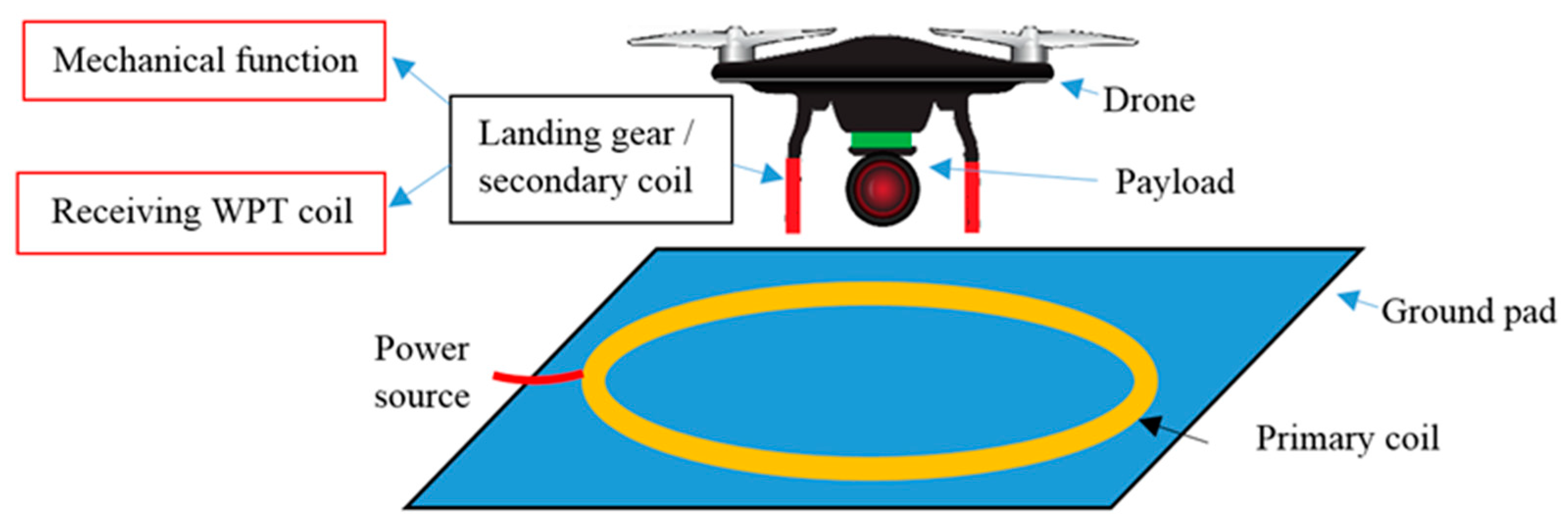
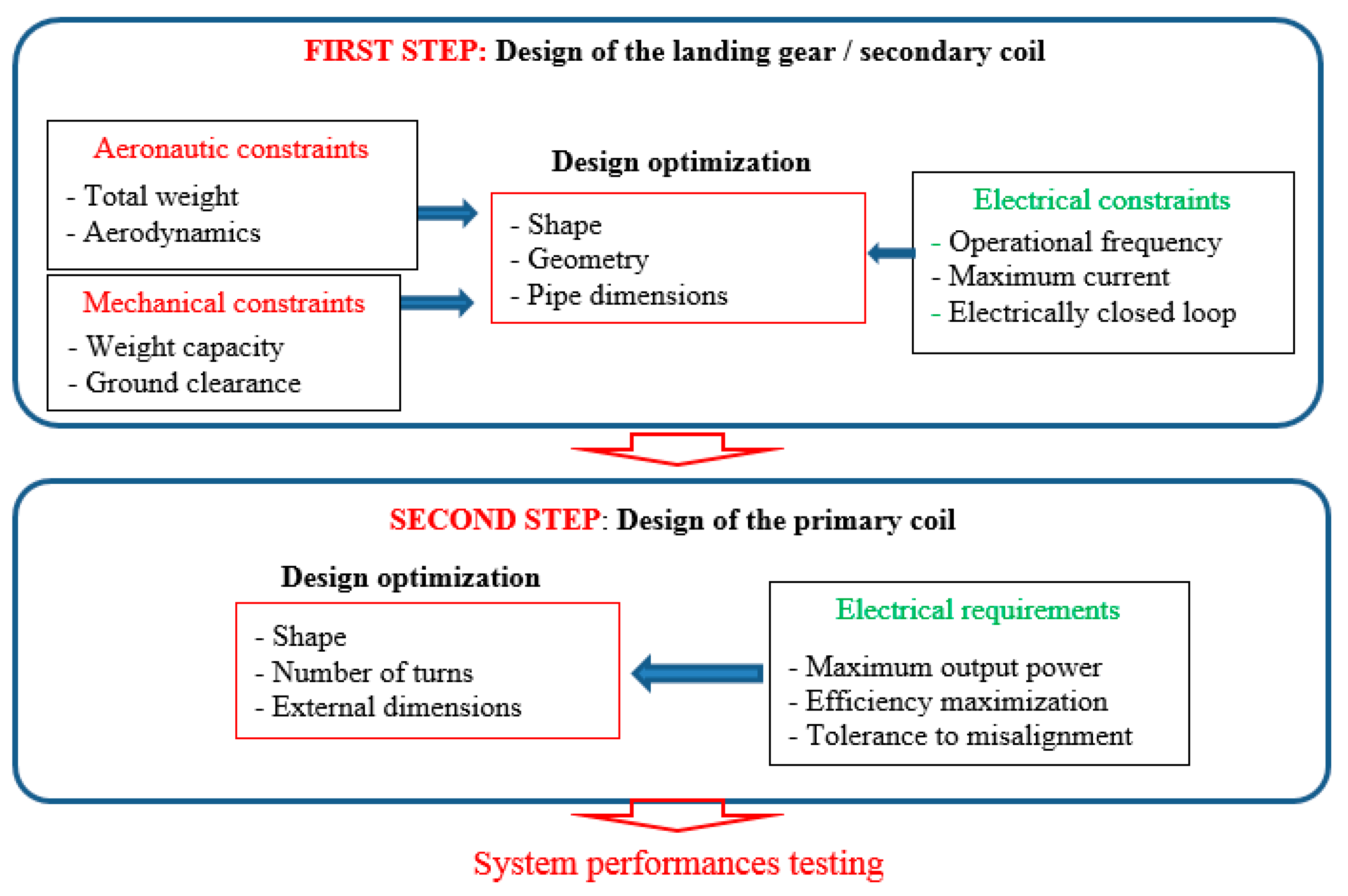
The scheme of the proposed WPT system is shown in Figure 1, where a sketch of the ground pad where the primary planar coil is mounted and of the non-planar secondary coil is illustrated. The design procedure of the charging system starts with the design of the onboard coil/landing gear that first of all must meet all mechanical requirements to provide an adequate suspension system during take-off and landing of the drone [31,32,33]. Then, the electrical design of the receiving coil is constrained by the mechanical design of the landing gear in terms of shape, height from ground, payload view, etc. Thus, only simple adjustments are made to the mechanical design of the landing gear to correctly operate as a secondary coil in the electrical design, e.g., electrical continuity or tubular shape. When the geometry of the secondary coil/landing gear has been fixed, the pipe is dimensioned to meet both mechanical (in terms of robustness) and electrical (in terms of AC resistance) functions. After the secondary coil configuration has been defined, the primary coil is designed in order to guarantee the electrical specifications in terms of transmitting power, efficiency, and tolerance to misalignment conditions. The dimension, the shape, and the number of turns of the primary coil is optimized in order to find the best tradeoff between transmitted power and tolerance to misalignment. The electrical design and optimization procedure are described in detail in the following sections. A sketch of the proposed design is shown in Figure 2.
2.2. WPT Equivalent Circuit
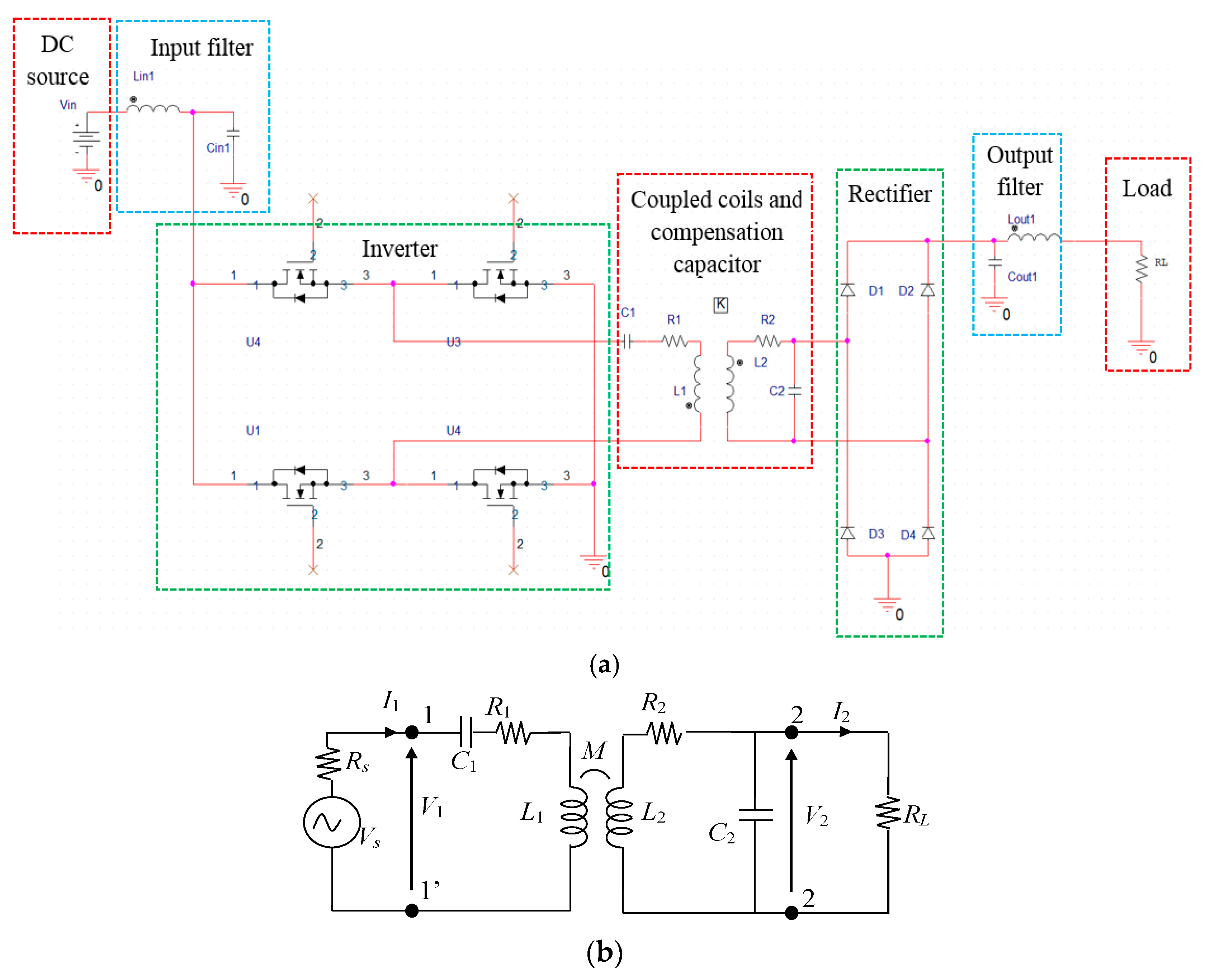
The WPT technology allows to transfer electrical energy by means of magnetic resonant coupling between two inductively coupled coils [34]. The primary coil is mounted in a ground base station, while the secondary coil is mounted on-board the drone. The complete electrical circuit of a WPT system is shown in Figure 3a. The first block is the DC source used to power the charging system, then there is an input filter block (inductor Lin1 and capacitor Cin1) to smooth the current spikes generated by the commutations of the inverter. The inverter permits the conversion from DC to high frequency AC signal. Generally, for medium–high power applications at the considered frequency of 300 kHz, the class-D topology inverter is used to reduce conduction and commutation losses. This inverter topology is made by four switches (in this case, the MOSFETs U1–U4) that permits to generate a full square wave with an easy control of the signal frequency.
Capacitance compensation networks are added on both transmitting and receiving coils to achieve resonance [7] and to improve the electrical performance of the system. There are several configurations of compensation networks that can be used in a WPT system. The most widely used are the capacitive series-series (SS) and series-parallel (SP) topologies, where “series” means that an additional capacitor is series connected with the coil, while “parallel” means that the additional capacitor is in parallel with the coil. The first letter of the topology abbreviation refers to the primary (or transmitting) circuit and the second one to the secondary (or receiving) circuit.
The high frequency AC signal given from the inverter is used to directly power the transmitting coil through the compensation capacitor C1. The two coils are characterized by self-inductances L1 and L2, mutual inductance M, and self-resistances R1 and R2 modeling the power losses [9]. The coupling factor k is given by:
The coil lumped inductances (L1, L2, and M) can be extracted by numerical simulations or calculated by analytical methods for simple configurations. The lumped parameters can be also measured using an RLC meter or a vector network analyzer (VNA). After the assessment of the lumped circuit parameters, the compensation capacitors C1 and C2 can be obtained at resonance frequency for the selected compensation topology [7].
On the receiving side, the secondary coil is connected to the compensation capacitor C2, then the high frequency AC signal is converted in a DC voltage by a full bridge diode rectifier (D1–D4). Finally, the output voltage is filtered and connected to load. Generally, the load is composed by many electronic components (electronic equipment, battery charger, etc.), but for the sake of simplicity, the whole load can be modeled at resonance with a simple resistor to evaluate the system performances.
The electrical performance of the WPT system, i.e., efficiency and transferred power, is obtained by the analysis of an equivalent simplified circuit shown in Figure 3b, derived from the complete circuit with SP compensation topology shown in Figure 3a, where the excitation block is modeled by Thevenin theorem with a simple sinusoidal voltage source Vs with an internal resistance Rs, and the load is modeled by an equivalent resistance RL [9]. The transferred power P2 = RL|I2|2 is the real power transferred to the load resistance RL, while the efficiency η = P2/P1 is calculated as the ratio between the output real power P2 at port 2-2’ and the input real power P1 at port 1-1’ [14]. It should be noted that in the calculation formula of the efficiency η, the losses of the inverter and of the rectifier are not considered.
2.3. Landing Gear Design as a Secondary Coil
The landing gear is here assumed to perform both structural and electrical functions. To this aim, the shape and the material of the landing gear is very important to guarantee mechanical robustness and good electrical performance. The configuration of the landing gear must follow the requirements of the drone in terms of mechanical and electrical functions. Furthermore, the landing gear must not interfere with the viewing area of the onboard payloads (camera, lidar, etc.). The shape of the landing gear depends on the drone characteristics. This aspect is very important, since it permits to apply the proposed wireless charging system to every kind of drone. The design procedure starts with the definition of the geometry of the landing gear according to the drone requirements and specifications, then the landing gear material and pipe dimension are defined. Typically, the landing gear in lightweight drones is made of plastic or fiber composite (e.g., carbon fiber or Kevlar fiber). These materials are characterized by low weight and good mechanical characteristics. However, to realize a landing gear with suitable electrical properties in order to fulfill the function of a secondary coil, you need to use a material with good electrical conductivity. Both plastic-based and fiber composite materials have negligible or very low conductivity at the WPT operational frequency, and for this reason they are not suitable for this application [35]. To overcome this issue, the landing gear is assumed to be realized using an aluminum pipe, a material with excellent mechanical characteristics: low weight, very good electrical conductivity, and limited additional AC losses due to the skin effect. From an electric point of view, the use of an aluminum hollow tube permits to minimize the skin effect losses and therefore the AC resistance of the coil. The skin depth δ can be calculated as:
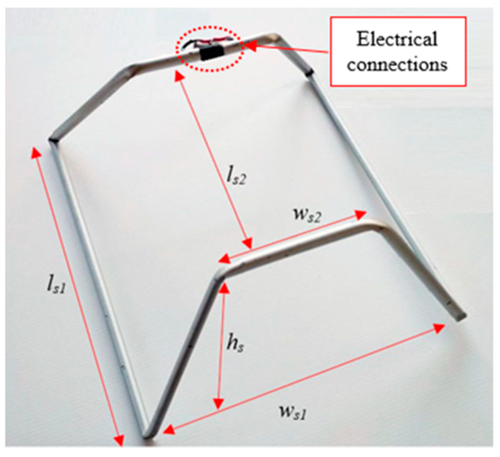
where μ is the permeability, σ is the conductivity, and f is the frequency. At the considered operational frequency f = 300 kHz and for the electrical conductivity of the aluminum tube σAl = 37 MS/m, the skin depth is δ = 0.15 mm. It is important that the geometry of the landing gear is suitably selected to form a closed loop and to guarantee electrical continuity. Moreover, the shape of the landing gear as a secondary coil must improve the coupling factor k with the primary coil. The proposed shape is shown in Figure 4, where it is worth noting that the landing gear is made by a continuous aluminum pipe terminated in the secondary circuit with attached load (not depicted in the picture). In this work a medium size commercial drone is considered (DJI F550, SZ DJI Technology Co. Ltd. , Shenzhen, China) that is characterized by a maximum takeoff weight of 2.5 kg. To ensure a good mechanical robustness, the aluminum pipe is chosen having the external diameter of the pipe equal to dp = 8 mm and a thickness equal to tk = 1 mm, which is a value much larger than the skin depth δ = 0.15 mm, leading to limited additional AC losses. The dimensions of the landing gear are: ls1 = 30 cm, ls2 = 20 cm, ws1 = 25 cm, ws2 = 15 cm, and hs = 10 cm. The weight of the realized landing gear, which can operate as a secondary coil, is mc = 91 g, while the original landing gear without any electrical function has a weight of 78 g. The additional weight is therefore only 13 g.
2.4. Design of the Primary Coil
The design of the primary coil is addressed to enhance the coupling factor k and the efficiency η. Contrary to the usual design, in the proposed application, the three-dimensional configuration of the secondary coil (shape, size, number of turns, etc.) is first designed, since it is used as landing gear. Then, the electromagnetic design is focused to maximize the electrical performance of the WPT system, varying mainly the primary coil configuration since the secondary coil configuration is fixed. The electrical parameters to be optimized are the coupling factor k and the efficiency η. The first design choice consists of the selection of the adequate shape of the primary coil to get a high coupling factor k. Since the primary coil must be installed in a pad inside the ground base station where the drone must land, it is convenient to design the primary coil as a planar coil that can be easily mounted in the pad. There are infinite solutions to design a planar coil, but the simplest one is based on the use of a multi-turn primary coil with circular or rectangular shape. Thus, these two different coil shapes are analyzed by a software tool, based on the numerical solution of the field equation, to calculate self and mutual inductances.
The magnetic flux φij produced by the ith current Ii and linked with the jth coil when assuming a single turn for both primary and secondary coils (N1 = N2 = 1) is given by:
where Ai is the magnetic vector potential produced by the current Ii, is the contour of the jth circuit, and i = {1, 2}, j = {1, 2}. Assuming the thin wire approximation, Ai is given by:
where r is the distance between the small size segment where the current Ii flows and the observation point where Ai is calculated.
For different shapes of the primary coil, the magnetic vector potential can be numerically calculated by approximating the integrals in Equations (3) and (4) as a series of ni discrete current segments Δm in the 3D space. Then the magnetic vector potential Ai is given by [36]:
where rm is the distance from the observation point and the center of the mth segment. The flux can be numerically calculated in the jth coil discretized by nj segments as:
The magnetic permeance Λij can be obtained from the flux φij as:
For two coupled coils with N1 and N2 number of turns, respectively, the self-inductances L1 and L2 and the mutual inductance M are obtained by the Equation (7) as:
Equations (8)–(10) are valid when all turns of each coil are linked with the same flux; however, in the case of small intra-turn spacing, the equation can be still used with good approximation. As in the considered application, the secondary coil has only one turn, N2 = 1, and Equations (8)–(10) become:
It is worth noting that in this case, the mutual inductance M12 is proportional to N1. The equations described above are implemented in a MATLAB code and they are used for the calculation and optimization of the coil parameters, as described in the following.
The outer dimensions of the transmitting coil are constrained by the size of the ground pad where the drone must land. This last depends on the expected landing accuracy and the size of the drone. Generally, precision landing techniques like infrared assisting pilot or Real Time Kinematic GPS permit to land within 20–25 cm. Assuming a drone with maximum outer dimension equal to ld, a ground pad of circular shape must have a diameter db equal to:
where a is the expected landing accuracy and b is a safety lateral margin.
Considering a square shape for the ground pad, the side sb of the square must be greater than or equal to the diameter db, i.e., sb ≥ db. In conclusion, the maximum dimensions of the ground pad for the two considered shapes are:
- 1)
- Circle of diameter db;
- 2)
- Square of side sb.
Obviously, the outer dimension of the primary coil must be lower than the outer dimension of the ground pad. The maximum electrical performance of the WPT system in terms of coupling factor k and efficiency η is therefore investigated considering the following two shapes for the single-turn (N1 = 1) primary coil:
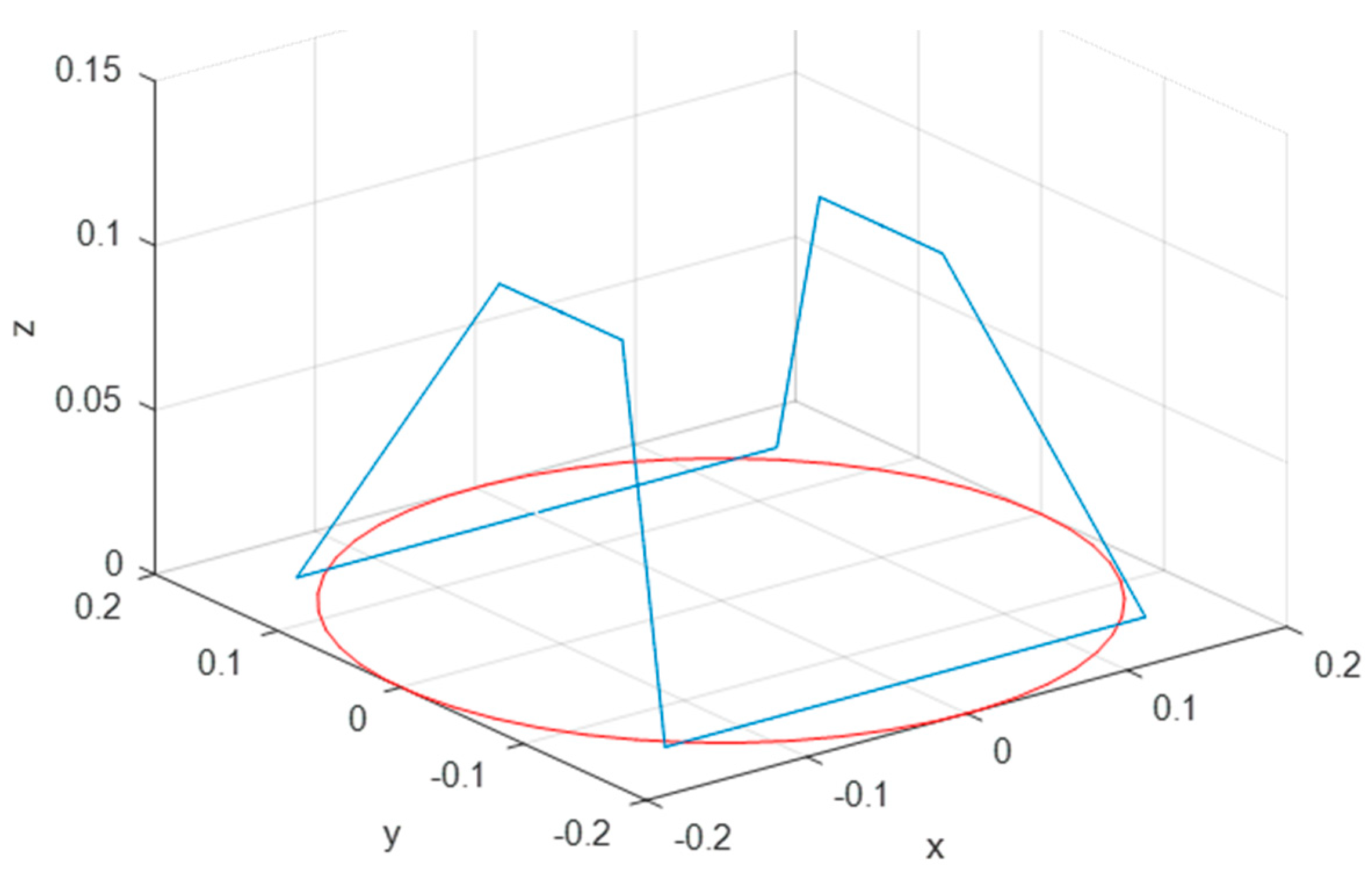
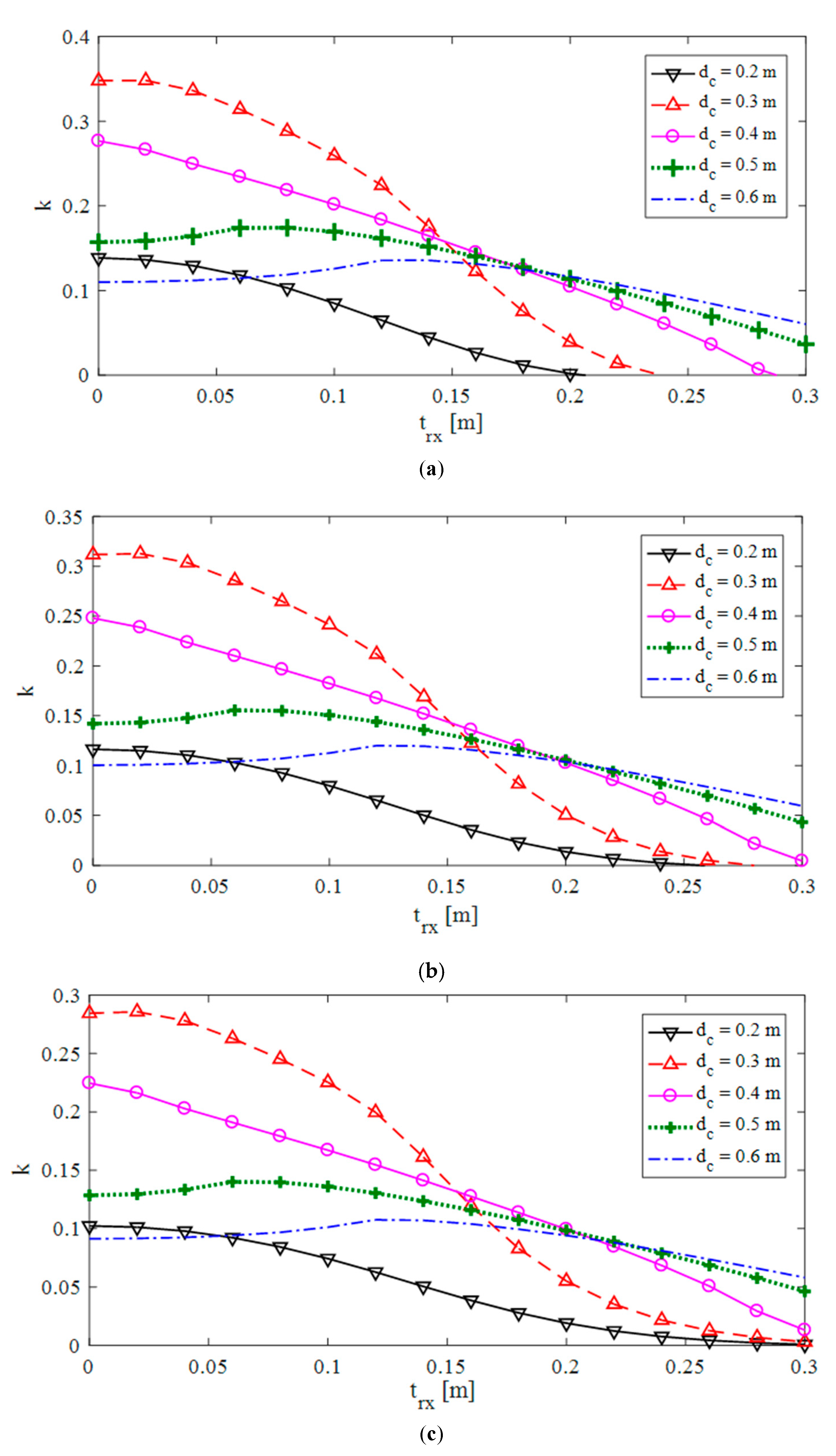
We have calculated k and η versus the variables dc or sc for the test cases #1 and #2, respectively. In our simulation, the adopted values are: dc = 20, 30, 40, 50, 60 cm; sc = 20, 30, 40, 50, 60 cm. The secondary is always a single-turn 3D coil (N2 = 1), whose dimensions are described in Section 2.3. The primary coil is assumed to be made of a copper Litz wire, while the secondary coil is made by a 3D-shaped aluminum pipe. The calculations are carried out considering a lateral misalignment between the projections of the two coils centers on the x−y plane at z = 0. The misalignment must be accurately considered, due to a possible imprecise landing of the drone. The results for a circular coil with variable diameter dc in terms of the coupling factor k versus lateral misalignment trx along x-axis are reported in Figure 7 for three different values of landing gear height hs. From this figure, it is evident that the coupling factor k increases as hs decreases.
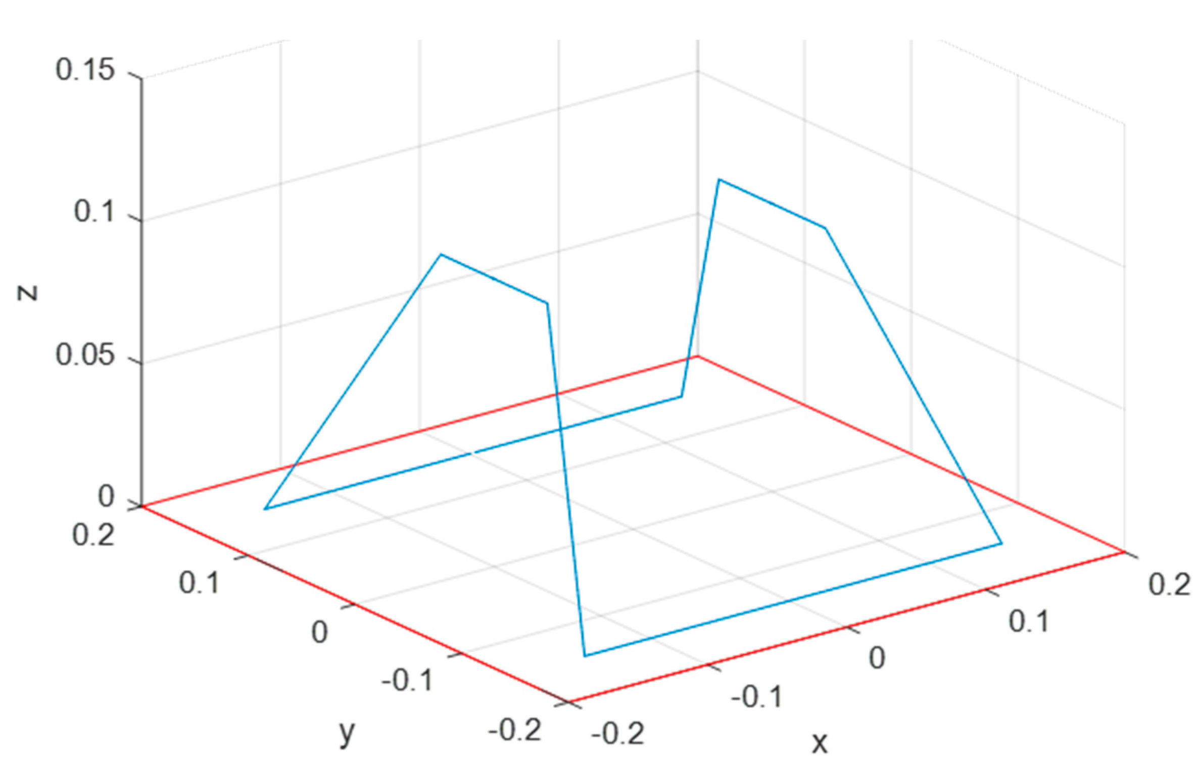
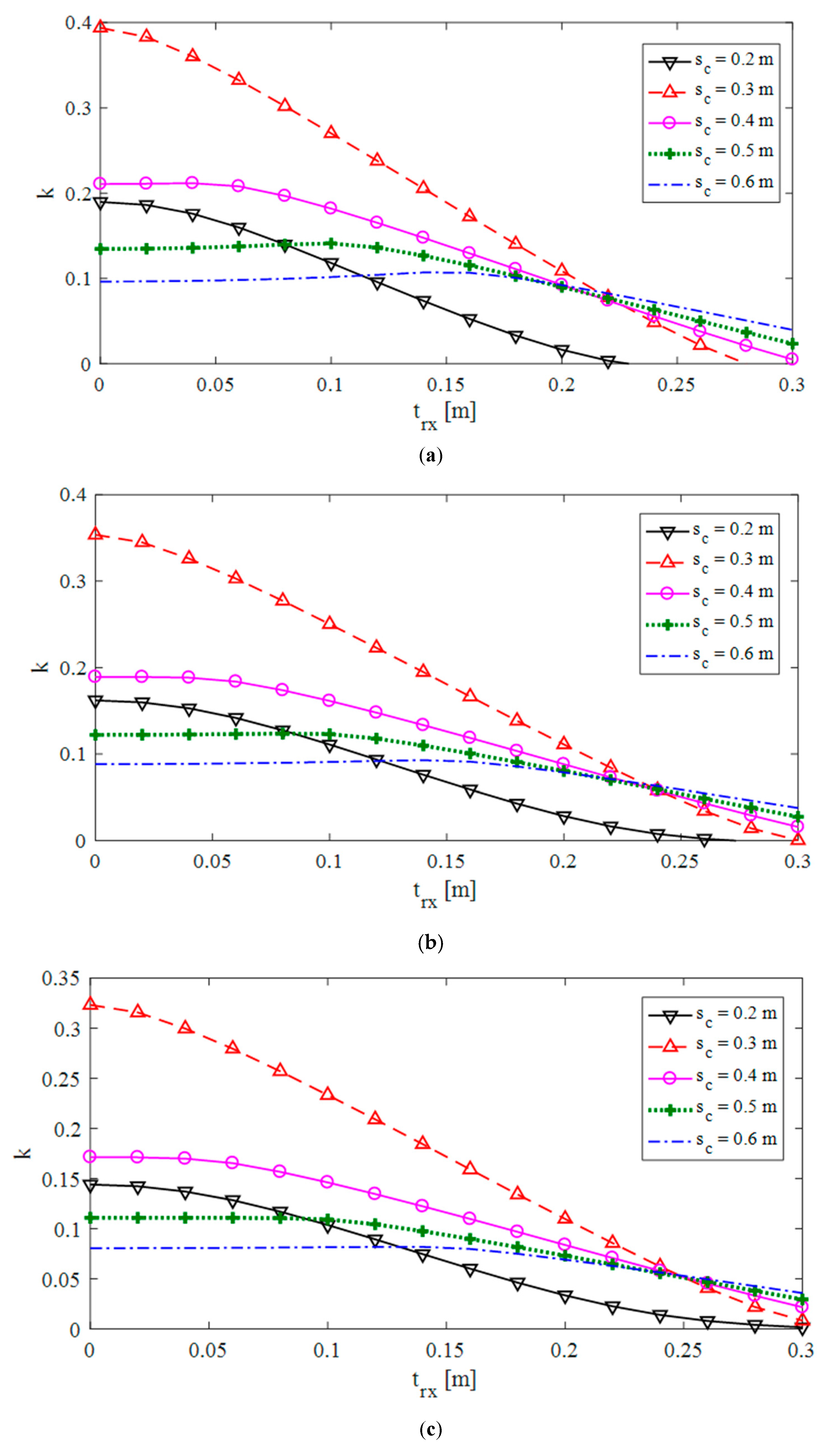
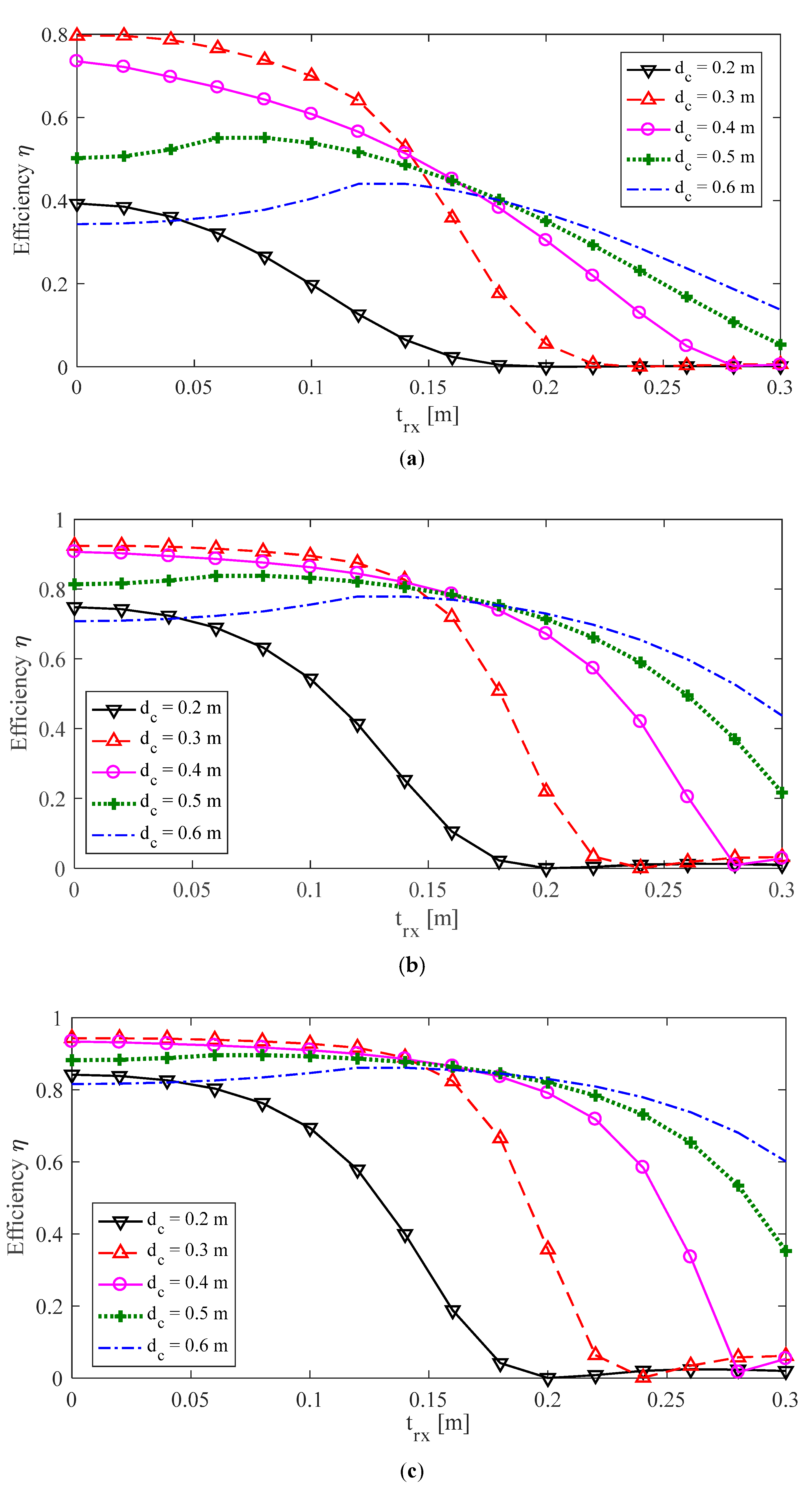
The coupling factor k versus lateral misalignment trx in x-direction is shown in Figure 8 when considering a primary square coil. From the obtained results, it is evident that the coupling factor k is maximum for aligned coils when the coil size is comparable with the projection of the 3D secondary coil on the x–y plane. In the considered case, this condition is verified for dc = 30 cm, being ws1 = 30 cm. The k value is much higher than that of other coil dimensions, but it rapidly decreases as the lateral misalignment. The k decrease appears also for other coils with different diameter dc, but this trend is not so rapid. This aspect is very relevant for stand-alone ground base stations, since any lack of charging due to a very imprecise landing requires human intervention. Thus, it is of paramount importance to assure an adequate charging of the drone battery, also in case of very poor landing. For this reason, it is highly suggested to select a large circular coil as the most adequate for the autonomous charging process of a drone, also in case of bad landing in a stand-alone ground base. Then, optimization in terms of system efficiency is proposed considering the circular coil configuration, which has been revealed to be better than the square shape, and assuming the SP compensation topology, which has been demonstrated to be the most performant topology [15]. The performance of the system is evaluated solving the equivalent circuit shown in Figure 3. The resonant frequency is assumed to be f = 300 kHz, which is the highest admissible frequency in the kilohertz range [37]. The load is modeled by a resistance RL = 5 Ω. The per unit length (p.u.l.) resistance of the Litz wire used for the primary coil is 10 mΩ/m, while the total resistance of the secondary coil is R2 = 28 mΩ. In order to optimize the efficiency η, an analysis varying the number N1 of the primary coil turns is carried out. The efficiency η versus the lateral misalignment trx is shown in Figure 9 for several values of the circular primary coil diameter dc and for three values of the primary coil turns: N1 = 1, 5, 10. The obtained results show that good values of η can also be found for small values of k when the lateral misalignment trx is limited. When the misalignment exceeds the landing precision a, fixed here to 20 cm, only the largest circular coils can efficiently power the battery. Thus, the configuration with dc = 50 cm as the outer diameter is selected as the optimum value of the primary circular coil.
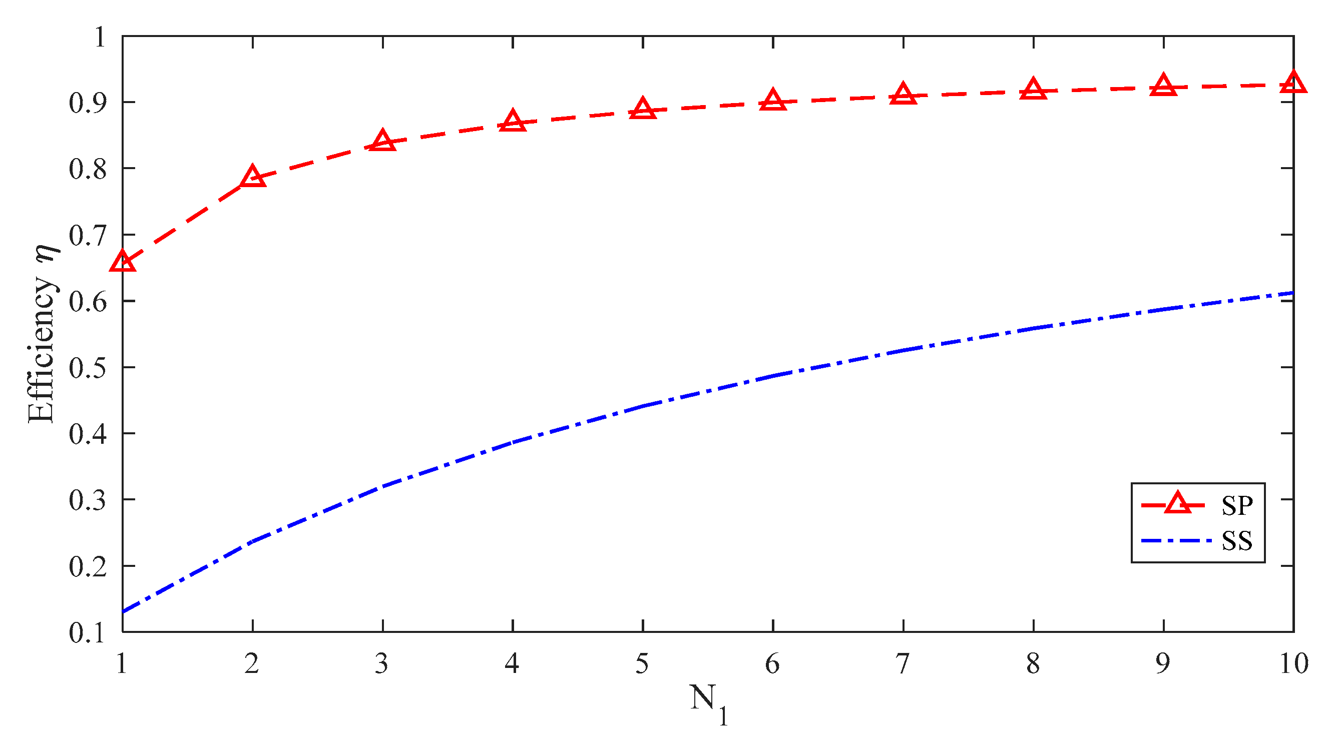
The system efficiency η versus the number of turns N1 = 1–10 of the primary coil is shown in Figure 10 when assuming dc = 50 cm. The results highlight that an increase of N1 significantly enhances the efficiency η. Thus, the configuration with N1 = 10 is chosen as design parameter. The efficiency is calculated assuming both SP and SS compensation topologies, demonstrating that the selection of the SP topology is much more convenient than the SS one, because it permits to obtain higher performances with low turns on the receiving coil [14,15]. It should be noted that increasing the number of turns more than N1 = 10 could lead to a slight improvement of the performance, but also to a significant increase of the coil weight and complexity.
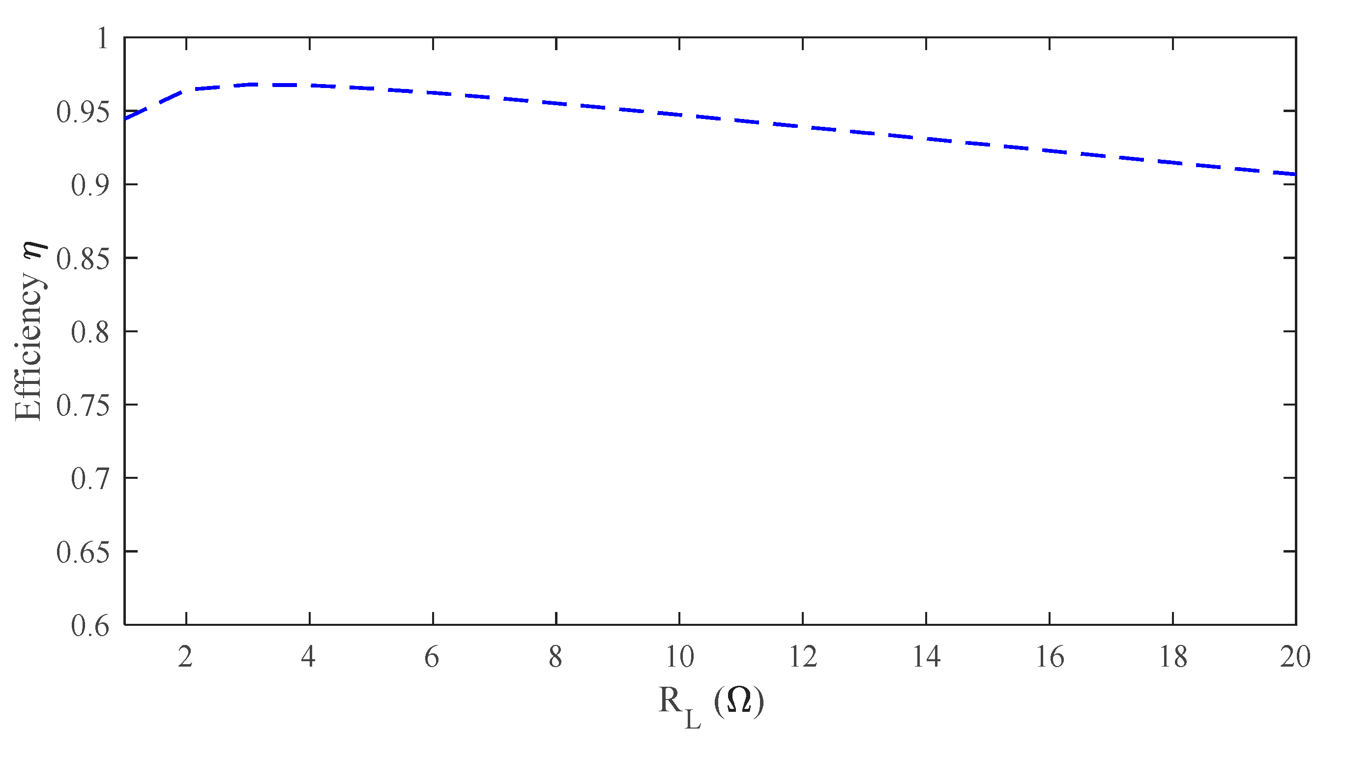
Finally, the system efficiency with SP compensation is investigated for variable load resistance RL, corresponding to different conditions of the battery during the charging process [38]. Thus, it is important to verify the efficiency of the system for several values of RL. The obtained results, shown in Figure 11, demonstrate the capacity of the system to maintain very good efficiency for a wide range of RL values.
In conclusion, the geometry of the primary coil can be optimized for a specific drone with a fixed 3D-shaped secondary coil/landing gear. The optimization constraints are the required misalignment tolerance a and the height from ground hs demanded by the drone and by the payload. However, it has been demonstrated that the proposed WPT system can work well also assuming a different size of the landing gear (e.g., height ht of the landing leg). It implies that the proposed design procedure can also be used for different landing gears, but, obviously, the optimization can be carried out only for a single landing gear on a case-by-case basis.
3. Fabrication and Testing
To validate the proposed numerical approach, a demonstrator of the WPT system for a commercial drone was realized and tested. A landing gear/receiving coil with the geometry described in Section 2.3 was fabricated using an aluminum pipe adequately shaped to form the secondary coil. The first test was performed to validate the numerical results in terms of self and mutual inductances for different alignment conditions of the coupled coils. In the second test, the system was powered to measure the efficiency. Finally, the secondary circuit demonstrator was installed to the commercial drone and the charging process was experimentally tested.
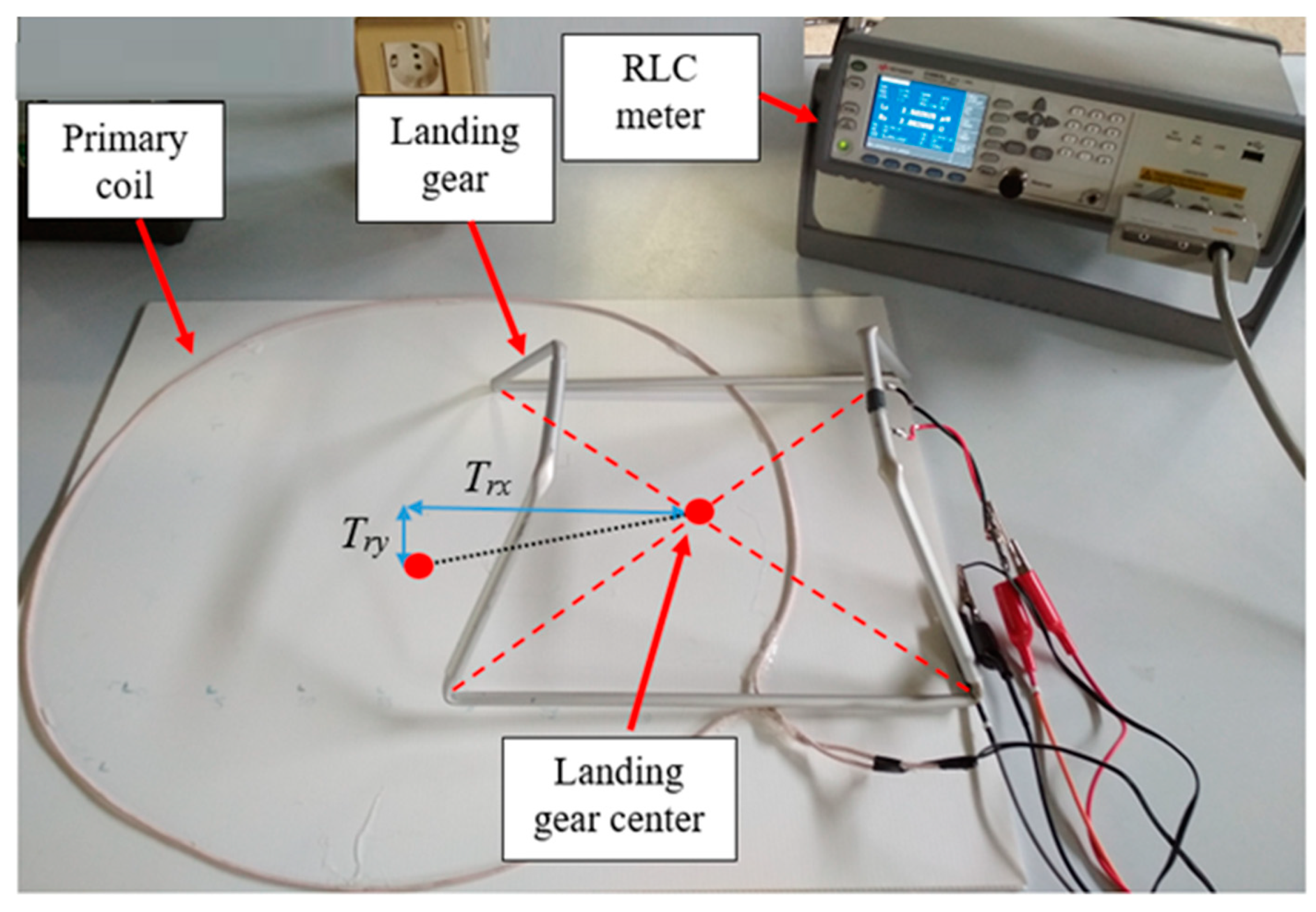
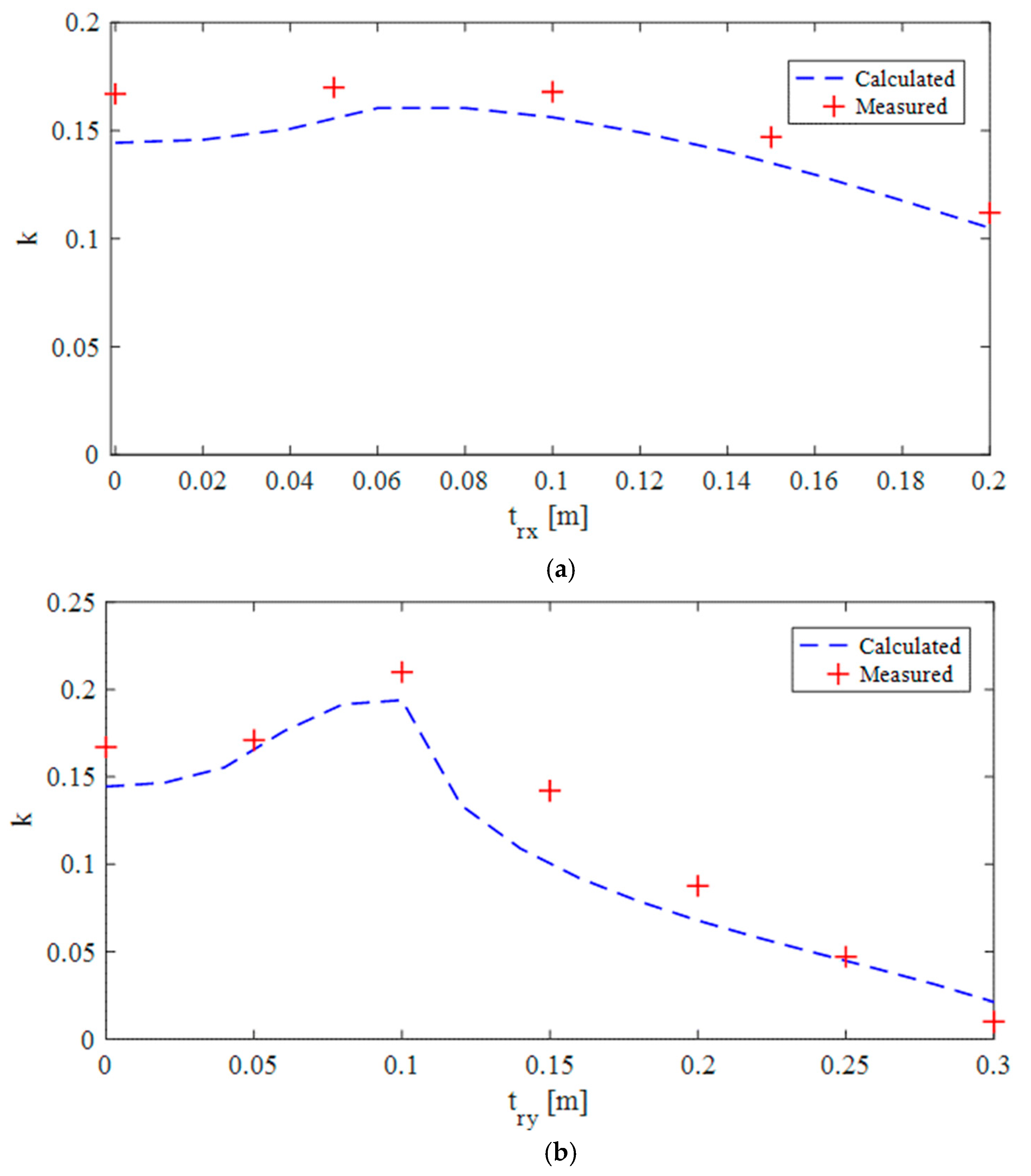
A circular 1-turn primary coil of diameter dc = 50 cm was realized using a copper Litz wire made of 120 strands of AWG 32 wire. The self-inductances of the primary coil L1 and of the landing gear/receiving coil L2 were measured using an RLC meter. The mutual inductance M was measured by connecting the two coils in series and anti-series configurations as M = (Xp − Xaph)/4ω, being ω the angular frequency, Xph and Xaph the reactance in phase and antiphase configurations, respectively. All the measurements were performed at f = 300 kHz. The setup of the primary and secondary coil and the instrumentation are shown in Figure 12. The calculated and measured lumped parameters are reported in Table 1, where M was measured in the case of aligned coils. The coupling factor k between the two coils was obtained by (1) considering misalignment conditions, named, respectively, trx and try in the x- and in the y- directions, respectively. The obtained results are shown in Figure 13. Then, a comparison in terms of efficiency η was performed. The circular primary coil obtained from the designing process described in Section 2.3 coil with N1 = 10 turns and outer diameter dc = 50 cm was adopted. The measured primary coil resistance made of Litz wire at f = 300 kHz is R1 = 830 mΩ and the self-inductance is L1 = 85 μH. The primary coil was fed by a high frequency class-D amplifier and compensated using a series capacitor C1 = 3.3 nF.
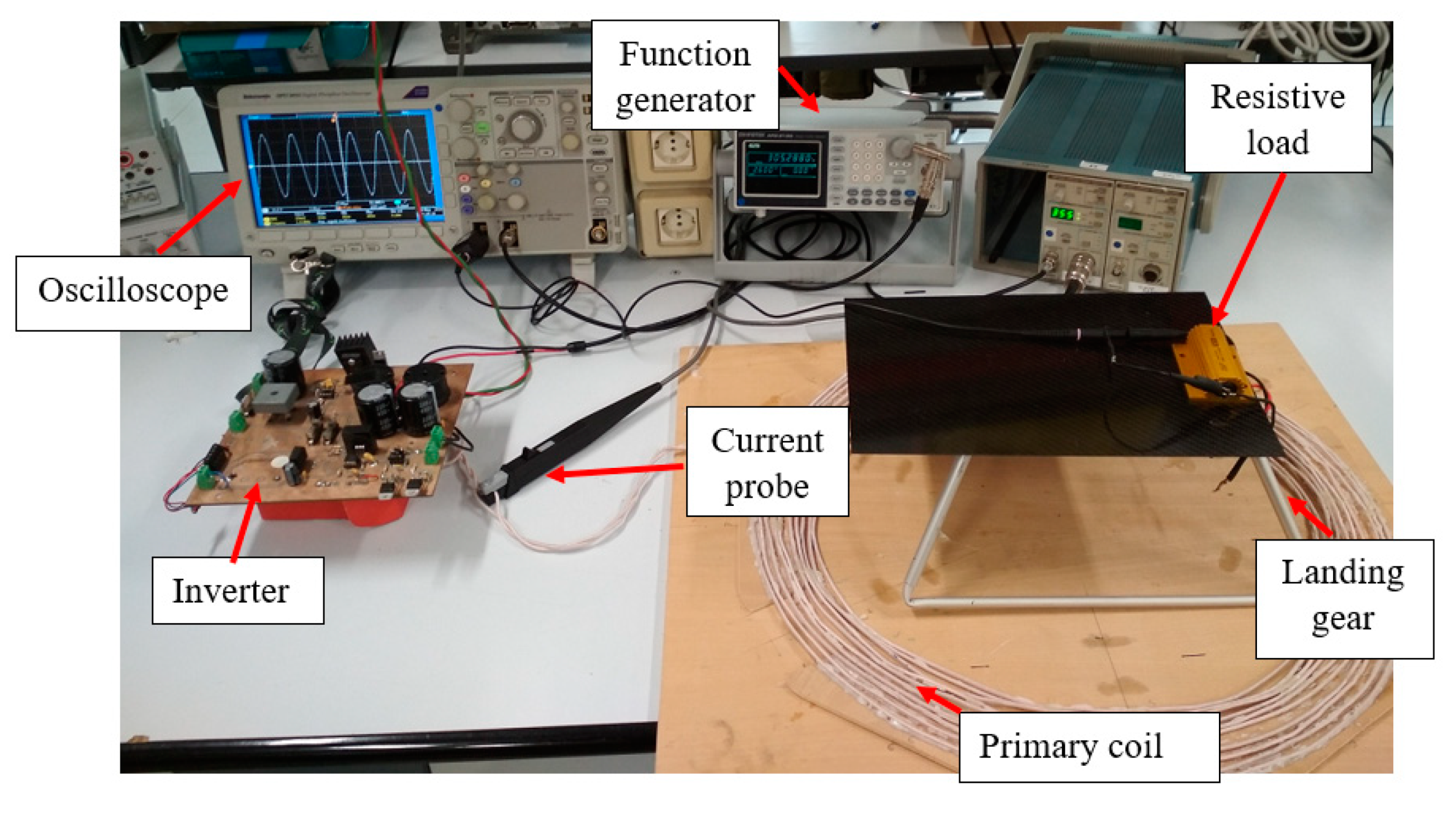
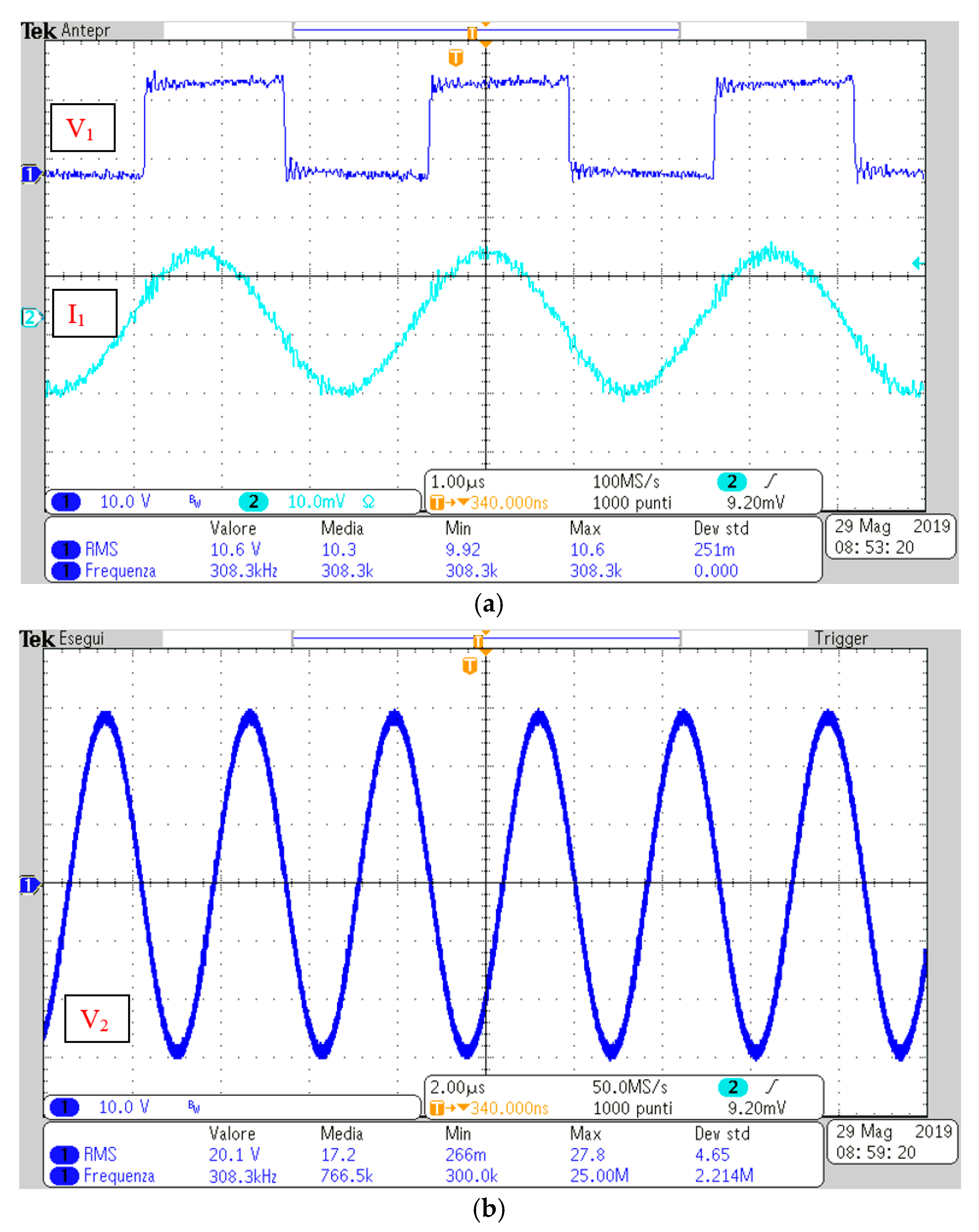
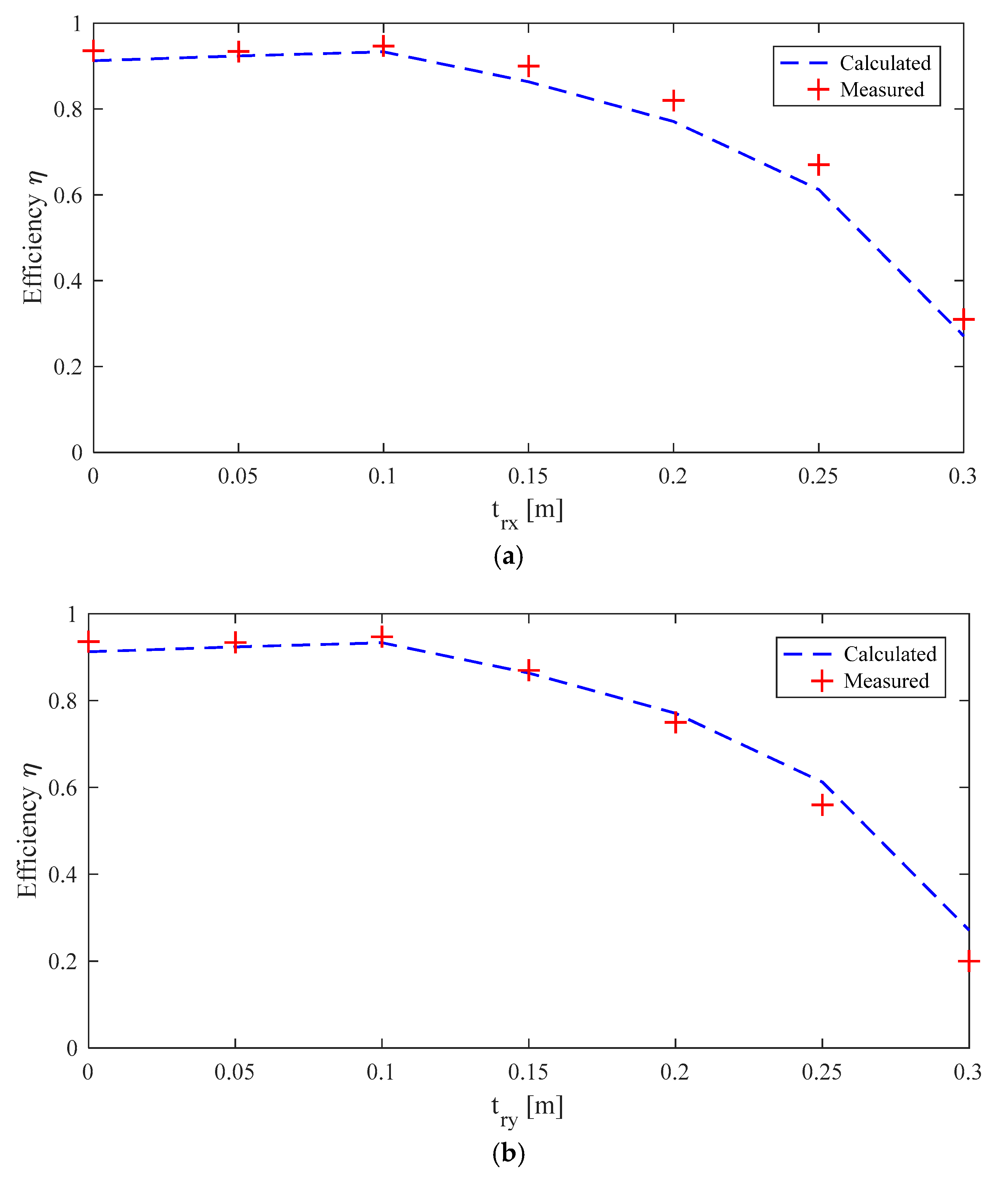
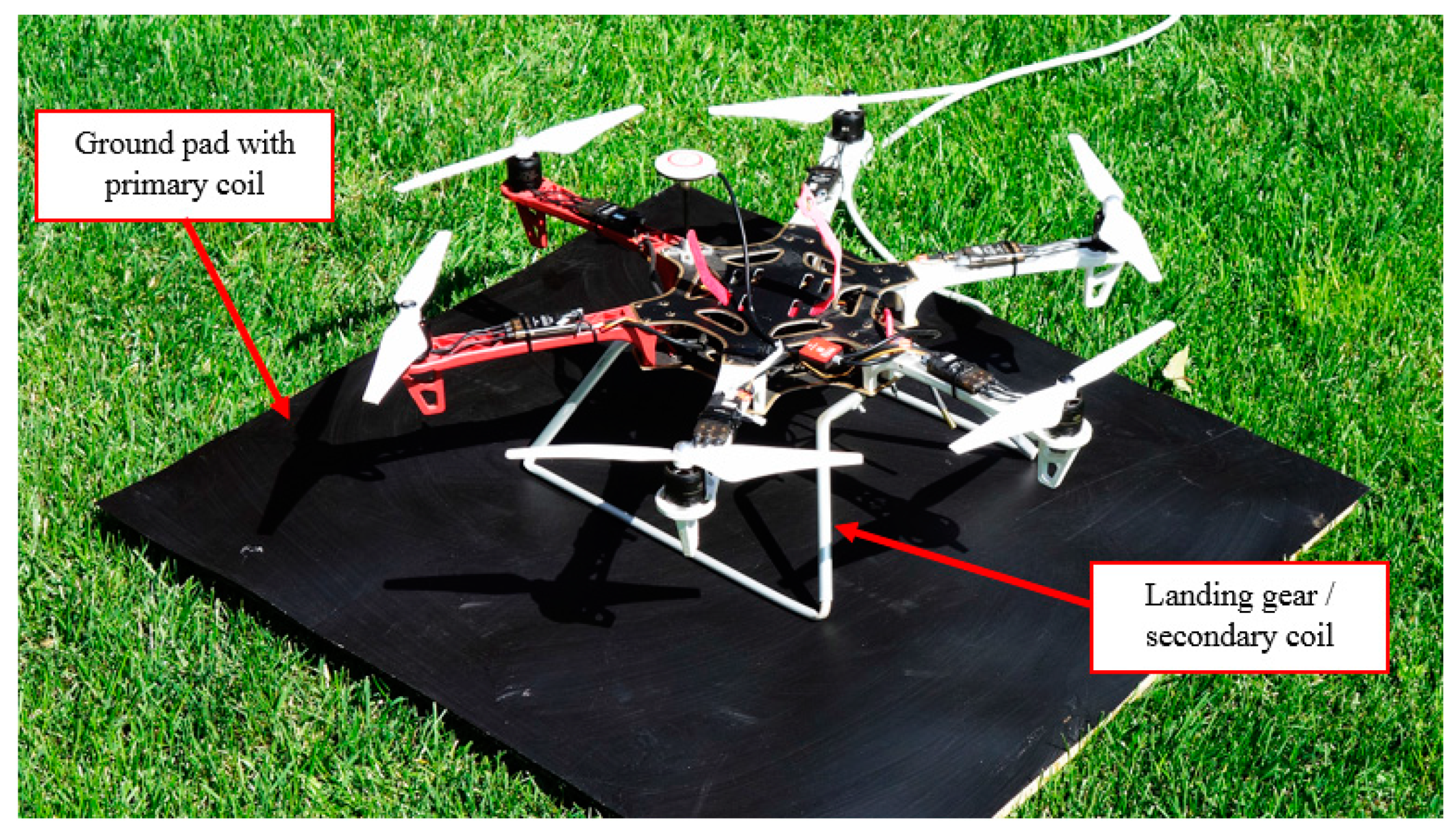
On the receiving side, the landing gear was compensated using a parallel capacitor C2 = 221 nF and connected to the resistive load. For simplicity, the load was modeled with a power resistor RL = 5 Ω. The DC input voltage on the inverter was manually adjusted in order to get, in all cases, a fixed output power load resistor. The required power by the considered drone was of 64 W, considering a battery with four cells (total nominal voltage 14.4 V), a capacity of 4000 mA·h, and a charging time of 1 h [14]. Considering the losses on the rectifier and on the charging circuit, the required power was set to PL = 70 W. The real power P1 = V1I1cosϕ1 was calculated from the measured voltage V1, current I1, and phase difference ϕ1 by means of an oscilloscope and a current probe clamp, while the output power PL = |V2|2/RL was derived by measuring the voltage drop V2 on the load resistance RL. The measurement setup is shown in Figure 14 and the measured waveforms of V1, I1, and V2 are shown in Figure 15. The efficiency η was measured and calculated for several misalignment conditions, i.e., different values of trx and try on x- and y-axes, respectively. The obtained results reported in Figure 16 show good agreement between calculations and measurements. Furthermore, the results exhibit the capability of the proposed solution to maintain very good efficiency also in condition of strong misalignment. Finally, the aluminum landing gear was installed on the drone, as shown in Figure 17, and the charging process was tested, adopting a rectifier and a charging control system between the WPT systems and the drone battery, as described in [14].
4. Conclusions
An innovative near-field WPT charging system for lightweight drones has been presented. The design is based on the modification of a pre-existent mechanical part of the drone to serve also as a receiving secondary coil. Specifically, in the proposed solution, the landing gear performs both mechanical and electrical functions. This new landing gear configuration makes the drone compatible with wireless charging without adding new parts and without significantly increasing the weight of the drone. To reduce the electrical losses and to maintain good mechanical characteristics, the landing gear is made of a 3D-shaped aluminum pipe. An optimization procedure for the design of the primary coil has been proposed to achieve good WPT electrical performance, while being highly tolerant to misalignment conditions of the coils. This last aspect is of paramount importance for ground base stations with automatic recharge of the drone battery after landing, because it eliminates or, at least, considerably reduces human interventions. A WPT demonstrator has been designed, realized, and tested after its installation on a commercial lightweight drone. The obtained numerical and experimental results demonstrate the validity of the proposed innovative solution for successful application of the near-field WPT technology to drones.
Author Contributions
T.C., S.C., F.M., and M.F. conceived and planned the experiments. T.C. carried out the experiments. S.C., F.M., and M.F. planned and carried out the simulations. All authors provided critical feedback, improved the final design, analyzed the data, and wrote the paper.
Funding
This research received no external funding.
Conflicts of Interest
The founding sponsors had no role in the design of the study; in the collection, analyses, or interpretation of data; in the writing of the manuscript; or in the decision to publish the results.
References
- Sujit, P.B.; Ghose, D. Search using multiple UAVs with flight time constraints. IEEE Trans. Aerosp. Electron. Syst. 2004, 40, 491–509. [Google Scholar] [CrossRef]
- Sarunic, P.; Evans, R. Hierarchical model predictive control of UAVs performing multitarget-multisensor tracking. IEEE Trans. Aerosp. Electron. Syst. 2014, 50, 2253–2268. [Google Scholar] [CrossRef]
- Lee, B.; Kwon, S.; Park, P.; Kim, K. Active power management system for an unmanned aerial vehicle powered by solar cells, a fuel cell, and batteries. IEEE Trans. Aerosp. Electron. Syst. 2014, 50, 3167–3177. [Google Scholar] [CrossRef]
- DIJ. Available online: https://www.dji.com/ (accessed on 14 September 2017).
- Lee, D.; Zhou, J.; Lin, W.T. Autonomous battery swapping system for quadcopter. In Proceedings of the 2015 International Conference on Unmanned Aircraft Systems (ICUAS), Denver, CO, USA, 9–12 June 2015; pp. 118–124. [Google Scholar]
- Knorr, S.; Puiatti, L.; Dallachiesa, M.; Puiatti, A. Charging Apparatus and Method for Electrically Charging Energy Storage Devices. U.S. Patent WO2015107199 A1, 23 July 2015. [Google Scholar]
- Covic, G.A.; Boys, J.T. Inductive power transfer. Proc. IEEE 2013, 101, 1276–1289. [Google Scholar] [CrossRef]
- Shinohara, N. Power without wires. IEEE Microw. Mag. 2011, 11, 64–73. [Google Scholar] [CrossRef]
- Campi, T.; Cruciani, S.; Maradei, F.; Feliziani, M. Near Field reduction in a Wireless Power Transfer System using LCC compensation. IEEE Trans. Electromagn. Compat. 2017, 59, 686–694. [Google Scholar] [CrossRef]
- Campi, T.; Cruciani, S.; De Santis, V.; Feliziani, M. EMF safety and thermal aspects in a pacemaker equipped with a wireless power transfer system working at low frequency. IEEE Trans. Microw. Theory Tech. 2016, 64, 375–382. [Google Scholar] [CrossRef]
- Jawad, A.M.; Nordin, R.; Gharghan, S.K.; Jawad, H.M.; Ismail, M. Opportunities and Challenges for Near-Field Wireless Power Transfer: A Review. Energies 2017, 10, 1022. [Google Scholar] [CrossRef]
- Vijayakumaran Nair, V.; Choi, J.R. An Efficiency Enhancement Technique for a Wireless Power Transmission System Based on a Multiple Coil Switching Technique. Energies 2016, 9, 156. [Google Scholar] [CrossRef]
- Feliziani, M.; Campi, T.; Cruciani, S.; Maradei, F.; Grasselli, U.; Macellari, M.; Schirone, L. Robust LCC compensation in wireless power transfer with variable coupling factor due to coil misalignment. In Proceedings of the 2015 IEEE 15th International Conference on Environment and Electrical Engineering (EEEIC), Rome, Italy, 10–13 June 2015. [Google Scholar]
- Campi, T.; Cruciani, S.; Feliziani, M. Wireless Power Transfer Technology Applied to an Autonomous Electric UAV with a Small Secondary Coil. Energies 2018, 11, 352. [Google Scholar] [CrossRef]
- Campi, T.; Dionisi, F.; Cruciani, S.; De Santis, V.; Feliziani, M.; Maradei, F. Magnetic field levels in drones equipped with wireless power transfer technology. In Proceedings of the Asia-Pacific International Symposium on Electromagnetic Compatibility (APEMC), Shenzhen, China, 17–21 May 2016; pp. 544–547. [Google Scholar]
- Junaid, A.B.; Konoiko, A.; Zweiri, Y.; Sahinkaya, M.N.; Seneviratne, L. Autonomous Wireless Self-Charging for Multi-Rotor Unmanned Aerial Vehicles. Energies 2017, 10, 803. [Google Scholar] [CrossRef]
- Choi, C.H.; Jang, H.J.; Lim, S.G.; Lim, H.C.; Cho, S.H.; Gaponov, I. Automatic wireless drone charging station creating essential environment for continuous drone operation. In Proceedings of the 2016 International Conference on Control, Automation and Information Sciences (ICCAIS 2016), Ansan, Korea, 27–29 October 2016; pp. 132–136. [Google Scholar]
- He, X.; Bito, J.; Tentzeris, M.M. A drone-based wireless power transfer and communications platform. In Proceedings of the IEEE Wireless Power Transfer Conference (WPTC), Taipei, Taiwan, 10–12 May 2017; pp. 1–4. [Google Scholar]
- Mostafa, T.M.; Muharam, A.; Hattori, R. Wireless battery charging system for drones via capacitive power transfer. In Proceedings of the 2017 IEEE PELS Workshop on Emerging Technologies: Wireless Power Transfer (WoW), Chongqing, China, 20–22 May 2017; pp. 1–6. [Google Scholar]
- Simic, M.; Bil, M.; Vojisavljevic, V. Investigation in Wireless Power Transmission for UAV Charging. Proc. Comput. Sci. 2015, 40, 1846–1855. [Google Scholar] [CrossRef]
- Lu, M.; Bagheri, M.; James, A.P.; Phung, T. Wireless Charging Techniques for UAVs: A Review, Reconceptualization, and Extension. IEEE Access 2018, 6, 29865–29884. [Google Scholar] [CrossRef]
- Aldhaher, S.; Mitcheson, P.D.; Arteaga, J.M.; Kkelis, G.; Yates, D.C. Light-weight wireless power transfer for mid-air charging of drones. In Proceedings of the 2017 11th European Conference on Antennas and Propagation (EUCAP), Paris, France, 19–24 March 2017; pp. 336–340. [Google Scholar]
- Song, C.; Kim, H.; Kim, Y.; Kim, D.; Jeong, S.; Cho, Y.; Lee, S.; Ahn, S.; Kim, J. EMI Reduction Methods in Wireless Power Transfer System for Drone Electrical Charger Using Tightly Coupled Three-Phase Resonant Magnetic Field. IEEE Trans. Ind. Electron. 2018, 65, 6839–6849. [Google Scholar] [CrossRef]
- Zhou, J.; Zhang, B.; Xiao, W.; Qiu, D.; Chen, Y. Nonlinear Parity-Time-Symmetric Model for Constant Efficiency Wireless Power Transfer: Application to a Drone-in-Flight Wireless Charging Platform. IEEE Trans. Ind. Electron. 2019, 66, 4097–4107. [Google Scholar] [CrossRef]
- Wang, C.; Ma, Z. Design of wireless power transfer device for UAV. In Proceedings of the 2016 IEEE International Conference on Mechatronics and Automation (IEEE ICMA 2016), Harbin, China, 7–10 August 2016; pp. 2449–2454. [Google Scholar]
- Muharam, A.; Mostafa, T.M.; Hattori, R. Design of power receiving side in wireless charging system for UAV application. In Proceedings of the ICSEEA 2017 International Conference on Sustainable Energy Engineering and Application, Jakarta, Indonesia, 23–24 October 2017; pp. 133–139. [Google Scholar]
- Rohan, A.; Rabah, M.; Talha, M.; Kim, S.-H. Development of Intelligent Drone Battery Charging System Based on Wireless Power Transmission Using Hill Climbing Algorithm. Appl. Syst. Innov. 2018, 1, 44. [Google Scholar] [CrossRef]
- Ure, N.K.; Chowdhary, G.; Toksoz, T.; How, J.P.; Vavrina, M.A.; Vian, J. An automated battery management system to enable persistent missions with multiple aerial vehicles. IEEE/ASME Trans. Mechatron. 2015, 20, 275–286. [Google Scholar] [CrossRef]
- Ke, D.; Liu, C.; Jiang, C.; Zhao, F. Design of an effective wireless air charging system for electric unmanned aerial vehicles. In Proceedings of the Proceedings IECON 2017 - 43rd Annual Conference of the IEEE Industrial Electronics Society, Beijing, China, 29 October–1 November 2017. [Google Scholar]
- Campi, T.; Feliziani, M. Carrello di Atterraggio Per Aereomobili (Droni). IT Patent, 102018000001311, 18 January 2018. [Google Scholar]
- Hadi, G.S.; Varianto, R.; Trilaksono, B.R.; Budiyono, A. Autonomous UAV System Development for Payload Dropping Mission. J. Instrum. Autom. Syst. 2015, 1, 72–77. [Google Scholar] [CrossRef]
- Muskardin, T.; Balmer, G.; Persson, L.; Wlach, S.; Laiacker, M.; Ollero, A.; Kondak, K. A Novel Landing System to Increase Payload Capacity and Operational Availability of High Altitude Long Endurance UAVs. J. Intell. Robot. Syst. Theory Appl. 2017, 88, 597–618. [Google Scholar] [CrossRef]
- Hou, Y.X.; Guan, Y.L.; Jia, H.G.; Bo, L.; Ma, W.Y. The dynamics research on the composite undercarriage of the Unmanned Aerial Vehicle. In Proceedings of the 2015 IEEE International Conference on Mechatronics and Automation (ICMA 2015), Beijing, China, 2–5 August 2015. [Google Scholar]
- Zhang, W.; Mi, C.C. Compensation topologies of high-power wireless power transfer systems. IEEE Trans. Veh. Technol. 2016, 65, 4768–4778. [Google Scholar] [CrossRef]
- Campi, T.; Cruciani, S.; De Santis, V.; Maradei, F.; Feliziani, M. Numerical Calculation of the Near Field Shielding for Carbon Fiber Reinforced Polymer (CFRP) Panels at Wireless Power Transfer Automotive Frequencies. In Proceedings of the 2018 IEEE Symposium on Electromagnetic Compatibility, Signal Integrity and Power Integrity (EMC, SI & PI), Long Beach, CA, USA, 30 July–3 August 2018; pp. 444–447. [Google Scholar]
- Tatum, J.B. Physics Topics: Electricity and Magnetism. 6 September 2006. Available online: http://astrowww.phys.uvic.ca/~tatum/elmag.html (accessed on 27 May 2019).
- Wireless Power Consortium. Available online: https://www.wirelesspowerconsortium.com/ (accessed on 15 March 2019).
- Cruciani, S.; Campi, T.; Feliziani, M. Parametric analysis of load variation in WPT systems applied to AIMDs. In Proceedings of the 46th European Microwave Conference (EuMC), London, UK, 3–7 October 2016. [Google Scholar]
Figure 1.
Sketch of the wireless power transfer (WPT) system for drone applications.

Figure 2.
Block diagram of the proposed system design.

Figure 3.
WPT charging system with series-parallel (SP) compensation: complete electrical circuit (a), and simplified equivalent circuit of two coupled coils (b).
Figure 3.
WPT charging system with series-parallel (SP) compensation: complete electrical circuit (a), and simplified equivalent circuit of two coupled coils (b).

Figure 4.
Landing gear configuration.

Figure 5.
WPT system with primary single coil of circular shape (red) and three-dimensional (3D) secondary coil (blue).
Figure 5.
WPT system with primary single coil of circular shape (red) and three-dimensional (3D) secondary coil (blue).

Figure 6.
WPT system with primary single coil of square shape (red) and 3D secondary coil (blue).

Figure 7.
Coupling factor k versus lateral misalignment trx along x-axis for circular coil, for different landing gear height: hs = 0.1 m (a), hs = 0.15 m (b) and hs = 0.2 m (c).
Figure 7.
Coupling factor k versus lateral misalignment trx along x-axis for circular coil, for different landing gear height: hs = 0.1 m (a), hs = 0.15 m (b) and hs = 0.2 m (c).

Figure 8.
Coupling factor k vs. lateral misalignment trx along x-axis for square coil, for different landing gear height: hs = 0.1 m (a), hs = 0.15 m (b) and hs = 0.2 m (c).
Figure 8.
Coupling factor k vs. lateral misalignment trx along x-axis for square coil, for different landing gear height: hs = 0.1 m (a), hs = 0.15 m (b) and hs = 0.2 m (c).

Figure 9.
Efficiency η vs lateral misalignment trx along x-axis for different values of the primary coil turns: N1 = 1 (a), N1 = 5 (b), and N1 = 10 (c).
Figure 9.
Efficiency η vs lateral misalignment trx along x-axis for different values of the primary coil turns: N1 = 1 (a), N1 = 5 (b), and N1 = 10 (c).

Figure 10.
System efficiency varying the number of turns N1 and the SP and SS compensation topologies.
Figure 10.
System efficiency varying the number of turns N1 and the SP and SS compensation topologies.

Figure 11.
System efficiency versus load resistance RL.

Figure 12.
Setup for the measurement of the coil circuit parameters.

Figure 13.
Calculated and measured coupling factor k vs misalignment along x-axis (a) and y-axis (b).
Figure 13.
Calculated and measured coupling factor k vs misalignment along x-axis (a) and y-axis (b).

Figure 14.
Measurement setup.

Figure 15.
Measured waveforms of V1 and I1 (a) and V2 (b).

Figure 16.
Calculated and measured efficiency η versus misalignments along x-axis (a) and y-axis (b).
Figure 16.
Calculated and measured efficiency η versus misalignments along x-axis (a) and y-axis (b).

Figure 17.
WPT demonstrator with aluminum landing gear applied to the DJI F550 drone.


Table 1.
Calculated and measured circuit lumped parameters for the primary coil with N1 = 1 and for the secondary coil/landing gear with N2 = 1.
Table 1.
Calculated and measured circuit lumped parameters for the primary coil with N1 = 1 and for the secondary coil/landing gear with N2 = 1.
| Calculated | Measured | ||||||||
|---|---|---|---|---|---|---|---|---|---|
| L1 (μH) | L2 (μH) | M (μH) | R1 (μΩ) | R2 (μΩ) | L1 (μH) | L2 (μH) | M (μH) | R1 (μΩ) | R2 (mΩ) |
| 2.20 | 1.33 | 0.28 | - | 28 | 2.25 | 1.27 | 0.29 | 65 | 33 |
© 2019 by the authors. Licensee MDPI, Basel, Switzerland. This article is an open access article distributed under the terms and conditions of the Creative Commons Attribution (CC BY) license (http://creativecommons.org/licenses/by/4.0/).
Share and Cite
MDPI and ACS Style
Campi, T.; Cruciani, S.; Maradei, F.; Feliziani, M. Innovative Design of Drone Landing Gear Used as a Receiving Coil in Wireless Charging Application. Energies 2019, 12, 3483. https://doi.org/10.3390/en12183483
AMA Style
Campi T, Cruciani S, Maradei F, Feliziani M. Innovative Design of Drone Landing Gear Used as a Receiving Coil in Wireless Charging Application. Energies. 2019; 12(18):3483. https://doi.org/10.3390/en12183483
Chicago/Turabian StyleCampi, Tommaso, Silvano Cruciani, Francesca Maradei, and Mauro Feliziani. 2019. "Innovative Design of Drone Landing Gear Used as a Receiving Coil in Wireless Charging Application" Energies 12, no. 18: 3483. https://doi.org/10.3390/en12183483
Note that from the first issue of 2016, this journal uses article numbers instead of page numbers. See further details here.