A Novel Filter Extracted Equivalent Control Based Fixed Frequency Sliding Mode Approach for Power Electronic Converters


Department of Electrical Engineering, Capital University of Science and Technology (CUST), Islamabad Expressway, Kahuta Road, Zone-V, Islamabad 44000, Pakistan
*
Author to whom correspondence should be addressed.
Energies 2019, 12(5), 853; https://doi.org/10.3390/en12050853
Submission received: 11 February 2019
/
Revised: 25 February 2019
/
Accepted: 26 February 2019
/
Published: 5 March 2019
(This article belongs to the Special Issue Control in Power Electronics)
Abstract
:The key issue in the implementation of the Sliding Mode Control (SMC) in analogue circuits and power electronic converters is its variable switching frequency. The drifting frequency causes electromagnetic compatibility issues and also adversely affect the efficiency of the converter, because the proper size of the inductor and the capacitor depends upon the switching frequency. Pulse Width Modulation based SMC (PWM-SMC) offers the solution, however, it uses either boundary layer approach or employs pulse width modulation of the ideal equivalent control signal. The first technique compromises the performance within the boundary layer, while the latter may not possess properties like robustness and order reduction due to the absence of the discontinuous function. In this research, a novel approach to fix the switching frequency in SMC is proposed, that employs a low pass filter to extract the equivalent control from the discontinuous function, such that the performance and robustness remains intact. To benchmark the experimental observations, a comparison with existing double integral type PWM-SMC is also presented. The results confirm that an improvement of 20% in the rise time and 25.3% in the settling time is obtained. The voltage sag during step change in load is reduced to 42.86%, indicating the increase in the robustness. The experiments prove the hypothesis that a discontinuous function based fixed frequency SMC performs better in terms of disturbances rejection as compared to its counterpart based solely on ideal equivalent control.
1. Introduction
Disturbance rejection, order reduction and capability to handle systems with un-modeled dynamics are the key properties of Sliding Mode Control (SMC) that make it a good choice to control non-linear systems with perturbations. The system under SMC becomes invariant to parametric changes and its performance is completely robust against matched disturbances [1,2,3,4]. Due to these properties, SMC finds a wide range of applications in motor control, PWM drives, power electronics, robotics, micro-grids and automotive control [5,6,7,8,9,10,11,12]. Moreover, the complexity of feedback control design is reduced by SMC because it decouples the system into reduced order dynamics [13].
In power electronic converters, the output voltage is controlled by switching the semi-conductor device between two states, ON and OFF. Thus, the control input can only take a value from the discrete set of . This particular nature of switching converter makes SMC an appropriate choice for controlling such circuits [14].
The SMC is ideally implemented using a discontinuous function that operates the switch at infinite frequency. Thus forcing the state trajectories to slide along the designed manifold towards the origin. However, it is not possible to achieve infinite switching frequency in physical systems. The first realistic approach towards SMC implementation is presented in [15], where the discontinuous sign function is replaced by a hysteresis comparator which is tuned to limit the maximum switching frequency according to the physical limits of the system. The scheme results in finite, but time varying switching frequency [16]. As a result, finite magnitude oscillations, known as chattering, appear in the output of the system [17]. The chattering is acceptable within limits for a particular system. However, the problem of variable switching frequency becomes a serious issue for electronic converters. They need a fixed frequency operation [18,19,20] because they consist of passive energy storing components (inductors and capacitors) and their correct size primarily depend upon the switching frequency. Moreover, the varying switching frequency degrades the power quality and makes it non-trivial to suppress electromagnetic interference (EMI) [21,22].
The researchers have proposed different methods to address the above-mentioned problem by fixing the switching frequency in SMC. A method using a comparator with adaptive hysteresis band is proposed in [23,24,25]. This method varies the hysteresis band such that the switching frequency remains fixed. This adaptation requires knowledge of the system states and consequently needs additional sensors and state observers that increase the implementation cost and complexity.
The schemes in [26,27,28,29] use an additional PI control loop that adjusts the width of the hysteresis band in order to achieve fixed switching frequency. This design requires the dynamics of the Frequency Control Loop (FCL) to be much slower as compared to the dynamics of the voltage and current control loops, as the faster dynamics may cause interaction with the outer control loops [26,27], hence the stability of the linearized system may not be ensured in this scenario [28,29]. In [30], the authors have proposed an FCL that monitors the time period of each switching cycle and compares it with a reference switching period. The difference in switching period is fed to a frequency regulation controller that updates the values of hysteresis band accordingly. The common drawback of these schemes is the addition of another control loop that increases the cost and complexity of the design.
The techniques presented in [31,32] demonstrate the use of external signal to enforce constant switching frequency in SMC. The scheme shows good results when the switching frequency is kept low as compared to the time constant of the system. However, if the frequency is increased, the system states drift away causing a steady state error.
In [33], Zero Average Dynamics (ZAD) method is used to achieve fixed switching frequency and is practically demonstrated in [34]. The scheme works by computing a duty ratio that ensures a zero T-periodic mean of the switching function. As a result the switching frequency is fixed during the steady state operation of the closed loop system. However, complex calculations and the compulsion of a fast processor are major drawbacks of this scheme. A second order sliding mode controller with constant switching frequency, utilizing the concept of state machine is presented in [35]. However, the requirements like fast analogue to digital converter and the need for an FPGA based processing module, limits its applications.
Fixed switching frequency in SMC using pulse width modulation (PWM) is reported in [36,37]. The authors have smoothened the control law within a boundary layer. In this boundary, the discontinuous function is replaced by a smooth linear function which is PWM implemented to achieve fixed switching frequency. The drawback of this technique is that it sacrifices the disturbance rejection performance in this boundary layer. The fixed switching frequency using PWM is also reported in [38,39,40,41,42,43,44,45]. However, in this work the ideal equivalent control signal, computed from the measured system states, is PWM modulated. The scheme is named as PWM-SMC. In [46,47], a bandwidth based parameter selection of the sliding surface is proposed for PWM-SMC. It is important to emphasize that in SMC, the robustness against unknown disturbances and parameter changes is achieved because of the discontinuous control term. However, in PWM-SMC, the ideal equivalent control does not evolve from a discontinuous function, rather it is computed from the measured states of the system, which may result in loss of inherent properties of SMC like order reduction and disturbance rejection [30,48]. It is important to mention that the actual equivalent control of the system can be extracted from the discontinuous control and its first evidence is found in [49], where chattering reduction is achieved by tuning the gain of the discontinuous function according to the Filter Extracted Equivalent Control (FEEC). The scheme achieves reduction in chattering amplitudes, however, the switching frequency of the system is not fixed.
Hence, it may be concluded that the existing techniques for fixing frequency in SMC are either too complex or they compromise one or the other properties of SMC. Consequently, there is a need for a comprehensive, fixed frequency SMC design which is low cost, simple to implement using commercially available integrated circuits (ICs) and also retains the inherent properties of SMC. Moreover, in the present era of industrialization, robust fixed frequency controllers for power electronic converters are a necessary need as they find applications in heating furnaces, speed drives of induction motors, fluorescent lamps, grid connected energy storage systems and regulated power supplies of modern electronic equipment [50,51,52].
This paper addresses the issue by proposing a novel method for fixing the switching frequency in SMC. The actual equivalent control of the system is extracted from the discontinuous function by means of a low pass filter and is used to achieve fixed frequency SMC which to the best of authors’ knowledge, has not been previously reported. The technique is implemented on a boost converter and the results are compared with existing PWM-SMC having a double integral type sliding surface. The experimental results demonstrate that the proposed technique achieves zero steady state error with improved dynamic response, and also exhibits better disturbance rejection properties as compared to PWM-SMC. The highlights of the contributions are:
- Achieving precise voltage regulation in presence of unknown load disturbances and un-modeled dynamics of the system.
- Extraction of the actual equivalent control from the discontinuous function under sliding mode operation.
- Improvement in both the dynamic response and the robustness of the closed loop system in comparison with double integral sliding mode control.
2. Proposed Technique
The proposed technique is demonstrated on a boost type DC-DC converter. Conventionally, the two state variables are the inductor current and the output voltage . Using circuit analysis techniques in Figure 1, the mathematical model of the converter is derived as:
where is the input voltage of the converter. The control input is denoted by u while . The inductance (H), capacitance (F) and load resistance () are denoted by L, C, . The power electronic converters are designed to operate as a switch and can be either ON or OFF. Therefore, the input signal of the converter is discrete in nature and mathematically . The value of control input with respect to the conduction state of the semiconductor switch is defined as:
The boost converters exhibit a non-minimum phase nature [53,54] which makes it more difficult to control as compared to other converters. The system becomes unstable if the feedback is designed based upon output voltage only [55]. However, the problem is solved by a cascade control scheme, where a two loop based structure is designed to control the inductor current and output voltage. This is an application of singular perturbation theory that can be applied where the motion rate of inner loop is much faster as compared to the outer loop [56,57]. The outer loop for voltage control is implemented using PI controller. Defining the error voltage as:
where and are the reference and output voltages respectively. A PI controller for the outer loop is designed as:
where and are the proportional and integral gains respectively while is the reference current for the inner current loop. If a feed forward reference current is also considered in (4), then the reference current is written as:
The equilibrium points of the system are obtained by setting the time derivatives in (1) to zero. Hence we get,
where and are the desired capacitor voltage and the inductor current at the equilibrium.
The sliding surface for the inner current loop is designed on the basis of current error as:
The control law that enforces to track is defined as:
The stability of the system can be ensured by applying the convergence condition . By using the dynamics of the system from (1) we get:
Since and using , we get . Hence (10) becomes:
The condition is satisfied if:
Stability condition in terms of the equivalent control can be written as:
Analysis of (12) shows that shall be greater than , in order to ensure the stable operation of the converter. It is important to note that when a physical converter is initially turned on, its output voltage may be less than . Practically this problem can be worked out by operating the system in an open loop manner and finally plugging in the controller when . For PWM based control, the problem can be solved by using a voltage limiter circuit that keeps the control signal less than the peak amplitude of the modulating ramp signal. This ensures the stable switching operation until . This paper also uses a voltage limiter circuit which is easily realized by using a zener diode.
Ideally, SMC operates the switch at infinite frequency, however, due to physical constraints the system needs to operate at finite frequency. This causes the state to oscillate within a boundary layer of width close to the sliding manifold . These oscillations consist of two components. The low frequency component coincides with equivalent control of the system and can be obtained from the actual discontinuous control by means of a low pass filter [4]. The time constant of the low pass filter shall be selected such that the low frequency component passes without any distortion while the high frequency component is removed. In this research, a first order low pass filter having time constant , where is the resistance and is the capacitance of the filter used. The mathematical relationship between the discontinuous control input u and the output of the filter is obtained using Kirchhoff’s voltage law as:
where is the instantaneous current through the filter capacitor. It is shown in [4,58] that the output of this filter gives under the following ideal condition:
where f is the switching frequency. As f increases, the motion of the states becomes more near to ideal SMC and the width in which the states oscillates, approaches zero. Hence as , . The necessary condition to filter out the high frequency component and extract is that the switching frequency must be much higher than or equivalently:
It is important to note that the FEEC contains information regarding the parameter changes and disturbances acting upon the system. The equivalent control under SMC coincides with the duty ratio of PWM converters [59,60], establishing the relationship which provides the basic theoretical background for development of PWM based SM-controllers. Once the is extracted, the control signal for PWM implementation is derived as:
where is the peak voltage of modulating ramp signal. The switching sequence provided by PWM according to (17) results in a fixed frequency operation of the SM-controller.
3. PWM-SMC with Double Integral Type Sliding Surface
For bench marking purpose, PWM-SMC is implemented and for the sake of completeness and better understanding, its design is also presented. In order to ensure best performance, a double integral type sliding surface is chosen [38,45]. The sliding manifold is defined as:
where . Mathematically, the ideal equivalent control signal for PWM-SMC is derived by putting . Thus we get:
Using (1) and (19) we get:
By using definition we get:
Choosing we derive as:
while
It is important to note that the magnitude of the ramp signal needs to be adaptively changed with respect to . This makes this technique robust to input voltage variations as compared to conventional PID controllers [40]. However, this adaptive nature of adds complexity to the design and causes over modulation of PWM signal during start up. Additional circuitry is required to prevent this over modulation. A salient feature of the proposed FEEC-SMC is that it achieves robustness against input voltage variations without requiring adaptive control of the ramp signal.
Stability of Inner Loop
Sliding mode can only exist on manifold if the following constraint is satisfied.
Using (1) and (18) we get:
The control law for the system is defined as:
when then (22) implies that . The control law turns . This gives the following condition:
where and . The output of both the op-amps calculating and are limited to and , thus mathematically:
Now by appropriate choice of , and the inequality (25) is satisfied.
When then the control law sets and stability is guaranteed if . By using Equation (23) we get the following condition:
Again by appropriate choice of design constants, (27) is satisfied. Finally, for the sake of protection the maximum duty cycle of the PWM output is limited to . This is accomplished by using a shunt voltage regulator TL431 at the output of the op-amp computing . TL431 cannot regulate voltages lower than 2.5 V. Hence and both are amplified by a gain of 2 and TL431 is adjusted to clip voltages above 4.8 V. This gain of 2 has no effect on the duty ratio because the same constant is multiplied in the numerator and denominator of the fraction. Thus the control law becomes:
4. Experimental Results and Discussion
The performance of the above-mentioned controllers is compared on the following basis of steady state error, transient response and robustness to load variations.
4.1. Experimental Setup
The parameters of the boost converter are shown in Table 1 while the complete schematic of the controller is shown in Figure 2. The electronic switch consists of a power MOSFET IRF540 with 0.06 channel resistance with maximum current capability of 20 A. The converter is operated with switching frequency of 32 kHz. It is important to note that increasing the switching frequency also increases the switching losses whereas lower switching frequency increases the chattering amplitude. Thus there is a compromise between the two factors. The efficiency of the converter also drops with increase in the switching frequency due to increase in switching losses. The efficiency of the boost converter is measured to be 93%.
It is observed experimentally that the equivalent resistance at the drain of the MOSFET shall be small enough to timely discharge the body diode capacitance, otherwise it may take a significantly longer time to discharge and hence the turn off time of the device may be adversely effected. A resistor of 47 k is placed between the gate and the source of the device to ensure the discharge of the gate capacitance. To measure instantaneous inductor current, a resistor of 0.47 is placed in the return path of the inductor current. By Ohm’s law inductor current . Hence the voltage sensed at is amplified by a gain of 2.1 to give exact value of the inductor current. All the waveforms presented in the paper are obtained using 70 MHz Rigol oscilloscope having sampling rate of 1 G samp/s. The control circuitry is powered with 0.1 V accurate power supply.
4.2. Steady State Error
Figure 3 presents the response of the boost converter with PWM-SMC. Figure 4 shows the response of the proposed FEEC-SMC. Both the controllers have zero steady state error and their output voltage converges to the desired 24 V as shown in Figure 3a and Figure 4a. It is worth mentioning that FEEC-SMC achieves zero steady state error without having any integral term in the sliding surface. This factor simplifies the design and makes the proposed technique cost effective as compared to the PWM-SMC design.
4.3. Transient Response
The transient response of the system is obtained by switching the input voltage at 0.4 Hz using Rigol function generator. The output of the function generator is applied to the base of an NPN transistor C1383 which drives a PNP power transistor TIP147 so that is connected and disconnected accordingly. The experimental results show that the rise time () for the PWM-SMC is 40 ms and its settling time () is 75 ms. The and for the closed loop system obtained using FEEC-SMC are 32 ms and 56 ms respectively. This indicates an improvement of 20% in and 25.3% in which is a direct consequence of the fact that the discontinuous function is directly implemented and no indirect approach is adopted to compute equivalent control.
4.4. Robustness to Load Variations
In order to establish the robustness of the proposed FEEC-SMC, experiments are conducted by abruptly increasing the load resistance. A switching network is used to increase the load by connecting a resistor of 47 in addition to the existing 82 load. Figure 3b shows that PWM-SMC exhibits an undershoot of 2.8 V while FEEC-SMC shows 42.86% improvement by reducing the voltage dip to 1.6 V as indicated in Figure 4b. PWM-SMC recovers in 250 s while FEEC-SMC recovers in 85 s which shows an improvement of 66% in recovery time. Experimental setup to evaluate the performance of the controllers is shown in Figure 5.
5. Conclusions
This research highlights the importance of the discontinuous function as the primary source of robustness and disturbance rejection in the domain of variable structure systems. However, it has a shortcoming in that its presence causes frequency drifts. This research reports a novel and intuitive method, namely FEEC-SMC, to achieve fixed frequency SMC by low pass filtration of the discontinuous function. An experimental comparison with PWM-SMC reveals that FEEC-SMC not only improves the dynamic response but also increases the robustness of the closed loop system against load variations and parameter drifts. Moreover, it achieves zero steady state error without any integral term in the sliding surface which gives it an advantage over PWM-SMC which requires a double integral type sliding surface to achieve zero steady state error. In contrast with PWM-SMC, the FEEC-SMC achieves robustness against input voltage variations without requiring complex adaptive control of the ramp signal. Finally, due to the direct implementation of a discontinuous function, FEEC-SMC retains the properties like order reduction and parameter invariance, which may be lost if the ideal equivalent control is constructed without involving a discontinuous function.
Future work may extend our results to other types of converters including Buck and C’uk converters and may also explore how to improve the robustness of micro-grids along with achieving precise voltage regulation.
Author Contributions
A.R.Y. has conducted the research and written the manuscript under the supervision of M.A. A.I.B. has helped in deriving the mathematical expression for the existence of the sliding mode control.
Acknowledgments
The authors would like to thank Capital University of Science and Technology.
Conflicts of Interest
The authors declare no conflict of interest.
References
- Pan, Y.; Yang, C.; Pan, L.; Yu, H. Integral Sliding Mode Control: Performance, Modification, and Improvement. IEEE Trans. Ind. Inform. 2018, 14, 3087–3096. [Google Scholar] [CrossRef]
- Nguyen, N.P.; Hong, S.K. Fault-tolerant Control of Quadcopter UAVs Using Robust Adaptive Sliding Mode Approach. Energies 2019, 12, 95. [Google Scholar] [CrossRef]
- Mobayen, S. Chaos synchronization of uncertain chaotic systems using composite nonlinear feedback based integral sliding mode control. ISA Trans. 2018, 77, 100–111. [Google Scholar] [CrossRef] [PubMed]
- Utkin, V.; Guldner, J.; Shi, J. Sliding Mode Control in Electro-Mechanical Systems; CRC Press: Boca Raton, FL, USA, 2009; Volume 34. [Google Scholar]
- Du, H.; Chen, X.; Wen, G.; Yu, X.; Lu, J. Discrete-Time Fast Terminal Sliding Mode Control for Permanent Magnet Linear Motor. IEEE Trans. Ind. Electron. 2018, 65, 9916–9927. [Google Scholar] [CrossRef]
- Kali, Y.; Ayala, M.; Rodas, J.; Saad, M.; Doval-Gandoy, J.; Gregor, R.; Benjelloun, K. Current Control of a Six-Phase Induction Machine Drive Based on Discrete-Time Sliding Mode with Time Delay Estimation. Energies 2019, 12, 170. [Google Scholar] [CrossRef]
- Liu, J.; Vazquez, S.; Wu, L.; Marquez, A.; Gao, H.; Franquelo, L.G. Extended state observer-based sliding-mode control for three-phase power converters. IEEE Trans. Ind. Electron. 2017, 64, 22–31. [Google Scholar] [CrossRef]
- Riani, A.; Madani, T.; Benallegue, A.; Djouani, K. Adaptive integral terminal sliding mode control for upper-limb rehabilitation exoskeleton. Control Eng. Pract. 2018, 75, 108–117. [Google Scholar] [CrossRef]
- Delghavi, M.B.; Yazdani, A. Sliding-Mode Control of AC Voltages and Currents of Dispatchable Distributed Energy Resources in Master-Slave-Organized Inverter-Based Microgrids. IEEE Trans. Smart Grid 2019, 10, 980–991. [Google Scholar] [CrossRef]
- Merabet, A. Adaptive Sliding Mode Speed Control for Wind Energy Experimental System. Energies 2018, 11, 2238. [Google Scholar] [CrossRef]
- Benhalima, S.; Miloud, R.; Chandra, A. Real-Time Implementation of Robust Control Strategies Based on Sliding Mode Control for Standalone Microgrids Supplying Non-Linear Loads. Energies 2018, 11, 2590. [Google Scholar] [CrossRef]
- Wang, H.; Shi, L.; Man, Z.; Zheng, J.; Li, S.; Yu, M.; Jiang, C.; Kong, H.; Cao, Z. Continuous Fast Nonsingular Terminal Sliding Mode Control of Automotive Electronic Throttle Systems Using Finite-Time Exact Observer. IEEE Trans. Ind. Electron. 2018, 65, 7160–7172. [Google Scholar] [CrossRef]
- Utkin, V.I. Sliding mode control design principles and applications to electric drives. IEEE Trans. Ind. Electron. 1993, 40, 23–36. [Google Scholar] [CrossRef] [Green Version]
- Alsmadi, Y.M.; Utkin, V.; Haj-Ahmed, M.; Xu, L.; Abdelaziz, A.Y. Sliding-mode control of power converters: AC/DC converters & DC/AC inverters. Int. J. Control 2018, 91, 2573–2587. [Google Scholar]
- Venkataramanan, R. Sliding Mode Control of Power Converters. Ph.D. Thesis, California Institute of Technology, Pasadena, CA, USA, 1986. [Google Scholar]
- Carpita, M.; Marchesoni, M. Experimental study of a power conditioning system using sliding mode control. IEEE Trans. Power Electron. 1996, 11, 731–742. [Google Scholar] [CrossRef]
- González, J.A.; Barreiro, A.; Dormido, S.; Baños, A. Nonlinear adaptive sliding mode control with fast non-overshooting responses and chattering avoidance. J. Franklin Inst. 2017, 354, 2788–2815. [Google Scholar] [CrossRef]
- Abeywardana, D.B.W.; Hredzak, B.; Agelidis, V.G. A fixed-frequency sliding mode controller for a boost-inverter-based battery-supercapacitor hybrid energy storage system. IEEE Trans. Power Electron. 2017, 32, 668–680. [Google Scholar] [CrossRef]
- Mohanty, P.R.; Panda, A.K. Fixed-frequency sliding-mode control scheme based on current control manifold for improved dynamic performance of boost PFC converter. IEEE J. Emerg. Sel. Top. Power Electron. 2017, 5, 576–586. [Google Scholar] [CrossRef]
- Gao, M.; Wang, D.; Li, Y.; Yuan, T. Fixed frequency pulse-width modulation based integrated sliding mode controller for phase-shifted full-bridge converters. IEEE Access 2018, 6, 2181–2192. [Google Scholar] [CrossRef]
- Nguyen, V.; Huynh, H.; Kim, S.; Song, H. Active EMI Reduction Using Chaotic Modulation in a Buck Converter with Relaxed Output LC Filter. Electronics 2018, 7, 254. [Google Scholar] [CrossRef]
- Pareschi, F.; Rovatti, R.; Setti, G. EMI reduction via spread spectrum in DC/DC converters: State of the art, optimization, and tradeoffs. IEEE Access 2015, 3, 2857–2874. [Google Scholar] [CrossRef]
- Chiarelli, C.; Malesani, L.; Pirondini, S.; Tomasin, P. Single-phase, three-level, constant frequency current hysteresis control for UPS applications. In Proceedings of the Fifth European Conference on Power Electronics and Applications, Brighton, UK, 13–16 September 1993; pp. 180–185. [Google Scholar]
- Holmes, D.G.; Davoodnezhad, R.; McGrath, B.P. An improved three-phase variable-band hysteresis current regulator. IEEE Trans. Power Electron. 2013, 28, 441–450. [Google Scholar] [CrossRef]
- Guzman, R.; de Vicuna, L.G.; Morales, J.; Castilla, M.; Matas, J. Sliding-mode control for a three-phase unity power factor rectifier operating at fixed switching frequency. IEEE Trans. Power Electron. 2016, 31, 758–769. [Google Scholar] [CrossRef]
- Huerta, S.C.; Alou, P.; Oliver, J.Á.; Garcia, O.; Cobos, J.A.; Abou-Alfotouh, A.M. Nonlinear Control for DC–DC Converters Based on Hysteresis of the CrmOUT Current With a Frequency Loop to Operate at Constant Frequency. IEEE Trans. Ind. Electron. 2011, 58, 1036–1043. [Google Scholar] [CrossRef]
- Huerta, S.C.; Alou, P.; Garcia, O.; Oliver, J.A.; Prieto, R.; Cobos, J. Hysteretic mixed-signal controller for high-frequency DC-DC converters operating at constant switching frequency. IEEE Trans. Power Electron. 2012, 27, 2690–2696. [Google Scholar] [CrossRef]
- Yan, W.T.; Ho, C.N.M.; Chung, H.S.H.; Au, K.T. Fixed-frequency boundary control of buck converter with second-order switching surface. IEEE Trans. Power Electron. 2009, 24, 2193–2201. [Google Scholar] [CrossRef]
- Malesani, L.; Mattavelli, P.; Tomasin, P. Improved constant-frequency hysteresis current control of VSI inverters with simple feedforward bandwidth prediction. IEEE Trans. Ind. Appl. 1997, 33, 1194–1202. [Google Scholar] [CrossRef] [Green Version]
- Repecho, V.; Biel, D.; Olm, J.M.; Colet, E.F. Switching frequency regulation in sliding mode control by a hysteresis band controller. IEEE Trans. Power Electron. 2017, 32, 1557–1569. [Google Scholar] [CrossRef]
- Silva, J.F.; Paulo, S.S. Fixed frequency sliding mode modulator for current mode PWM inverters. In Proceedings of the 24th Annual IEEE Power Electronics Specialists Conference - PESC ’93, Seattle, WA, USA, 20–24 June 1993; pp. 623–629. [Google Scholar]
- Mattavelli, P.; Rossetto, L.; Spiazzi, G.; Tenti, P. General-purpose sliding-mode controller for DC/DC converter applications. In Proceedings of the 24th Annual IEEE Power Electronics Specialists Conference - PESC ’93, Seattle, WA, USA, 20–24 June 1993; pp. 609–615. [Google Scholar]
- Fossas, E.; Grinó, R.; Biel, D. Quasi-Sliding control based on pulse width modulation, zero averaged dynamics and the L2 norm. In Advances in Variable Structure Systems: Analysis, Integration and Applications; World Scientific: Singapore, 2000; pp. 335–344. [Google Scholar]
- Ramos, R.R.; Biel, D.; Fossas, E.; Guinjoan, F. A fixed-frequency quasi-sliding control algorithm: Application to power inverters design by means of FPGA implementation. IEEE Trans. Power Electron. 2003, 18, 344–355. [Google Scholar] [CrossRef]
- Ling, R.; Maksimovic, D.; Leyva, R. Second-order sliding-mode controlled synchronous buck DC–DC converter. IEEE Trans. Power Electron. 2016, 31, 2539–2549. [Google Scholar] [CrossRef]
- Ye, J.; Malysz, P.; Emadi, A. A fixed-switching-frequency integral sliding mode current controller for switched reluctance motor drives. IEEE J. Emerg. Sel. Top. Power Electron. 2015, 3, 381–394. [Google Scholar]
- Abrishamifar, A.; Ahmad, A.; Mohamadian, M. Fixed switching frequency sliding mode control for single-phase unipolar inverters. IEEE Trans. Power Electron. 2012, 27, 2507–2514. [Google Scholar] [CrossRef]
- Yasin, A.R.; Ashraf, M.; Bhatti, A.I. Fixed Frequency Sliding Mode Control of Power Converters for Improved Dynamic Response in DC Micro-Grids. Energies 2018, 11, 2799. [Google Scholar] [CrossRef]
- Zaman, H.; Zheng, X.; Wu, X.; Khan, S.; Ali, H. A Fixed-Frequency Sliding-Mode Controller for Fourth-Order Class-D Amplifier. Electronics 2018, 7, 261. [Google Scholar] [CrossRef]
- Tan, S.C.; Lai, Y.; Tse, C.K.; Cheung, M.K. A fixed-frequency pulsewidth modulation based quasi-sliding-mode controller for buck converters. IEEE Trans. Power Electron. 2005, 20, 1379–1392. [Google Scholar] [CrossRef]
- Yasin, A.R.; Ashraf, M.; Bhatti, A.I. Fixed frequency sliding mode control of renewable energy resources in DC micro grid. Asian J. Control 2019. [Google Scholar] [CrossRef]
- Jazi, H.N.; Goudarzian, A.; Pourbagher, R.; Derakhshandeh, S.Y. PI and PWM Sliding Mode Control of POESLL Converter. IEEE Trans. Aerosp. Electron. Syst. 2017, 53, 2167–2177. [Google Scholar] [CrossRef]
- Al-Baidhani, H.; Kazimierczuk, M.K. PWM-based proportional-integral sliding-mode current control of DC-DC boost converter. In Proceedings of the 2018 IEEE Texas Power and Energy Conference (TPEC), College Station, TX, USA, 8–9 February 2018; pp. 1–6. [Google Scholar]
- Pradhan, R.; Subudhi, B. Double integral sliding mode MPPT control of a photovoltaic system. IEEE Trans. Control Syst. Technol. 2016, 24, 285–292. [Google Scholar] [CrossRef]
- Tan, S.C.; Lai, Y.M.; Tse, C.K. Indirect Sliding Mode Control of Power Converters Via Double Integral Sliding Surface. IEEE Trans. Power Electron. 2008, 23, 600–611. [Google Scholar] [Green Version]
- Tan, S.C.; Lai, Y.M.; Chi, K.T. General design issues of sliding-mode controllers in DC–DC converters. IEEE Trans. Ind. Electron. 2008, 55, 1160–1174. [Google Scholar]
- Teodorescu, M.; Stanciu, D. Sliding coefficients estimation for fixed frequency sliding mode control of boost converter. In Proceedings of the 2015 9th International Symposium on Advanced Topics in Electrical Engineering (ATEE), Bucharest, Romania, 7–9 May 2015; pp. 698–703. [Google Scholar]
- Wai, R.J.; Shih, L.C. Design of voltage tracking control for DC–DC boost converter via total sliding-mode technique. IEEE Trans. Ind. Electron. 2011, 58, 2502–2511. [Google Scholar] [CrossRef]
- Utkin, V.I.; Lee, H. The chattering analysis. In Proceedings of the 2006 IEEE 12th International Power Electronics and Motion Control Conference, Portoroz, Slovenia, 30 August–1 September 2006; pp. 2014–2019. [Google Scholar]
- Hu, Y.; Tan, C.; Broughton, J.; Roach, P.A.; Varga, L. Nonlinear dynamic simulation and control of large-scale reheating furnace operations using a zone method based model. Appl. Therm. Eng. 2018, 135, 41–53. [Google Scholar] [CrossRef]
- Kumar, Y.S.; Poddar, G. Medium-voltage vector control induction motor drive at zero frequency using modular multilevel converter. IEEE Trans. Ind. Electron. 2018, 65, 125–132. [Google Scholar] [CrossRef]
- Ghanaatian, M.; Lotfifard, S. Control of Flywheel Energy Storage Systems in the Presence of Uncertainties. IEEE Trans. Sustain. Energy 2019, 10, 36–45. [Google Scholar] [CrossRef]
- Sira-Ramirez, H. Sliding-mode control on slow manifolds of DC-to-DC power converters. Int. J. Control 1988, 47, 1323–1340. [Google Scholar] [CrossRef]
- Shabestari, P.; Gharehpetian, G.; Riahy, G.; Mortazavian, S. Voltage controllers for DC-DC boost converters in discontinuous current mode. In Proceedings of the 2015 International Energy and Sustainability Conference (IESC), Farmingdale, NY, USA, 12–13 November 2015; pp. 1–7. [Google Scholar]
- Alsmadi, Y.M.; Utkin, V.; Haj-ahmed, M.A.; Xu, L. Sliding mode control of power converters: DC/DC converters. Int. J. Control 2017. [Google Scholar] [CrossRef]
- Kokotovic, P.V.; O’Malley, R.E., Jr.; Sannuti, P. Singular perturbations and order reduction in control theory an overview. Automatica 1976, 12, 123–132. [Google Scholar] [CrossRef]
- Kokotović, P.V. Applications of singular perturbation techniques to control problems. SIAM Rev. 1984, 26, 501–550. [Google Scholar] [CrossRef]
- Utkin, V.I. Sliding Modes in Control and Optimization; Springer Science & Business Media: Berlin/Heidelberg, Germany, 2013. [Google Scholar]
- Morel, C.; Guignard, J.C.; Guillet, M. Sliding mode control of DC-to-DC power converters. In Proceedings of the 2002 9th International Conference on Electronics, Circuits and Systems, Dubrovnik, Croatia, 15–18 September 2002; Volume 3, pp. 971–974. [Google Scholar]
- Sira-Ramirez, H.J.; Ilic, M. A geometric approach to the feedback control of switch mode DC-to-DC power supplies. IEEE Trans. Circuits Syst. 1988, 35, 1291–1298. [Google Scholar] [CrossRef]
Figure 1.
Block diagram of the proposed filter extracted equivalent control based sliding mode control (FEEC-SMC) for voltage regulation in boost converter.
Figure 1.
Block diagram of the proposed filter extracted equivalent control based sliding mode control (FEEC-SMC) for voltage regulation in boost converter.

Figure 2.
Complete circuit diagram of the proposed FEEC-SMC.

Figure 3.
Experimental waveforms of the closed loop system with PWM-SMC. (a) Step response of the closed loop system. (b) Output voltage when load is shifted from 82 to 29.88 (c) Inductor current and gating signal at output of LM311 during steady state operation. (d) Chattering in the output voltage.

Figure 4.
Experimental waveforms of the closed loop system with FEEC-SMC. (a) Step response of the closed loop system. (b) Output voltage when load is shifted from 82 to 29.88 indicating robustness of the closed loop system. (c) Inductor current and gating signal at output of LM311 during steady state operation. (d) Chattering in the output voltage.

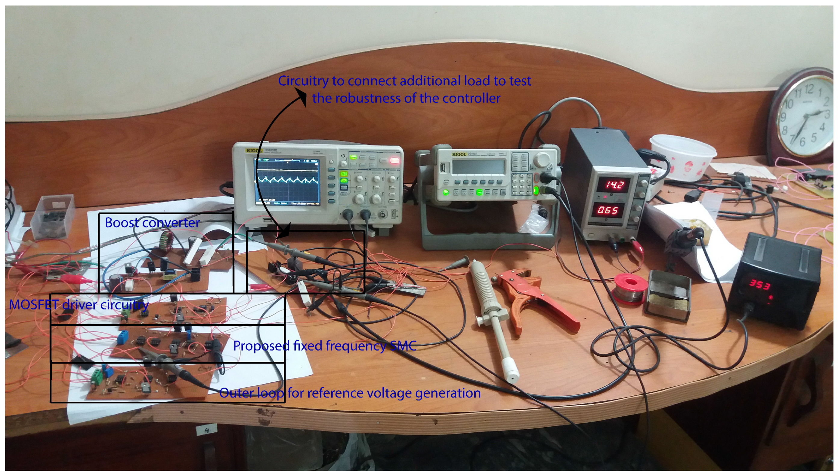
Figure 5.
Experimental setup to evaluate the performance of the controllers.


Table 1.
Parameters of Buck Converter.
| Description | Symbol | Value |
|---|---|---|
| Input voltage | 12 V | |
| Desired output voltage | 24 V | |
| Capacitance | C | 1000 F |
| Capacitor ESR | 21 m | |
| Inductance of coil | L | 100 H |
| Resistance of coil | 0.18 | |
| Switching frequency | 32 kHz | |
| Load resistance | 15–100 |
© 2019 by the authors. Licensee MDPI, Basel, Switzerland. This article is an open access article distributed under the terms and conditions of the Creative Commons Attribution (CC BY) license (http://creativecommons.org/licenses/by/4.0/).
Share and Cite
MDPI and ACS Style
Yasin, A.R.; Ashraf, M.; Bhatti, A.I. A Novel Filter Extracted Equivalent Control Based Fixed Frequency Sliding Mode Approach for Power Electronic Converters. Energies 2019, 12, 853. https://doi.org/10.3390/en12050853
AMA Style
Yasin AR, Ashraf M, Bhatti AI. A Novel Filter Extracted Equivalent Control Based Fixed Frequency Sliding Mode Approach for Power Electronic Converters. Energies. 2019; 12(5):853. https://doi.org/10.3390/en12050853
Chicago/Turabian StyleYasin, Abdul Rehman, Muhammad Ashraf, and Aamer Iqbal Bhatti. 2019. "A Novel Filter Extracted Equivalent Control Based Fixed Frequency Sliding Mode Approach for Power Electronic Converters" Energies 12, no. 5: 853. https://doi.org/10.3390/en12050853
Note that from the first issue of 2016, this journal uses article numbers instead of page numbers. See further details here.