Article

A Novel Hybrid-Fuel Storage System of Compressed Air Energy for China

Key Lab of Education Ministry for Power Plant Equipments Conditions Monitoring and Fault Diagnosis, North China Electric Power University, Beijing 102206, China
*
Author to whom correspondence should be addressed.
Energies 2014, 7(8), 4988-5010; https://doi.org/10.3390/en7084988
Submission received: 20 March 2014 / Revised: 14 July 2014 / Accepted: 23 July 2014 / Published: 4 August 2014
(This article belongs to the Special Issue Sustainable Energy Innovation: Strategies to Accelerate Progress)

Abstract

:
Compressed air energy storage (CAES) is a large-scale technology that provides long-duration energy storage. It is promising for balancing the large-scale penetration of intermittent and dispersed sources of power, such as wind and solar power, into electric grids. The existing CAES plants utilize natural gas (NG) as fuel. However, China is rich in coal but is deficient in NG; therefore, a hybrid-fuel CAES is proposed and analyzed in this study. Based on the existing CAES plants, the hybrid-fuel CAES incorporates an external combustion heater into the power generation subsystem to heat the air from the recuperator and the air from the high-pressure air turbine. Coal is the fuel for the external combustion heater. The overall efficiency and exergy efficiency of the hybrid-fuel CAES are 61.18% and 59.84%, respectively. Given the same parameters, the cost of electricity (COE) of the hybrid-fuel CAES, which requires less NG, is $5.48/MW∙h less than that of the gas-fuel CAES. Although the proposed CAES requires a relatively high investment in the current electricity system in North China, the proposed CAES will be likely to become competitive in the market, provided that the energy supplies are improved and the large scale grid-connection of wind power is realized.

1. Introduction

Global warming was initiated by increasing concentrations of CO2 and other greenhouse gases (GHG) in the atmosphere [1,2]. Since 2006, China has become the largest annual carbon emitter [3]. Wind energy and other clean technologies are significant contributors to reverse this difficult situation [4,5]. However, due to the intermittent nature and variability of wind power, the integration of large wind energy sources into the grid will affect its security and power quality. To reduce the negative effects that wind electricity brings to the grid, electric energy storage and peak load shaving must be widely employed. Currently, available technologies for electric energy storage include potential (e.g., compressed air energy storage (CAES) and pumped hydro storage (PHS)) [6,7], kinetic, thermal, and chemical energy storage. PHS and CAES are the most viable technologies for large-scale storage.
At present, PHS is a large capacity form of grid energy storage. It operates under special hydrologic and geographic conditions and adversely affects the environment. In addition to PHS, CAES is another technically proven solution for bulk energy storage. According to reported data [8,9], the investment required by a CAES power plant is far lower than that required by a PHS power plant with equivalent capacity.
In 1978, the first CAES plant (290 MW) was built in Huntorf, Germany [10]. In 1991, a 110 MW plant was constructed in McIntosh, AL, USA, and improved upon the Huntorf design by incorporating a recuperator (air-to-air heat exchanger) to preheat air from the cavern using exhaust heat from the turbines [11]. This plant has operated at over 95% reliability since it addressed its startup issues. The successful operations of the McIntosh and Huntorf plants demonstrate the technical viability of CAES technology with respect to ancillary services, load following, and the generation of intermediate power.
CAES remains a hot research topic given its vital role in the power grid. Research is mainly focused on system analysis and optimization, different kinds of fuels, integration with wind power, and techno-economic analysis.
Novel CAES systems have been analyzed and optimized in previous literature, including a hybrid wind-diesel-CAES system [12]. De Biasi [13] has also proposed methods to enhance energy storage. The second-generation CAES technology regulates smart grids, synchronizes reserves, and uniquely manages renewable energy, power demand, and peak shaving. Bullough et al. [14] proposed an adiabatic CAES (AA-CAES) which theoretically requires no fuel and offers a significant improvement in cycle efficiency.
CAES systems have been analyzed in terms of energy, exergy, and economy in the literatures. Hessami et al. [15] and Zafirakis et al. [16] both conducted economic analyses for CAES associated with wind power. Kim et al. [17] performed energy and exergy analyses of a micro-CAES system. Grazzini et al. [18] conducted a thermodynamic analysis of the multistage AA-CAES. Salgi et al. [19] analyzed the energy-balance effects of adding CAES to an energy-system. Kim et al. [20] conducted a numerical modeling study of coupled thermodynamic, multiphase fluid flow and heat transport associated with CAES. The estimated GHG emission rate of a CAES plant combined with wind power is one-fourth that of cycle plants combined with natural gas (NG) and approximately one-tenth of that of pulverized coal plants [21]. From the theoretical study of the characteristics of using various energy storage methods to strengthen the power networks and maintain load levels [22], we conclude that CAES is a profitable and mature storage technology. However, with respect to the incorporation of large-scale energy storage into similar installations of wind turbines, CAES should therefore be investigated further.
In 2011, the wind power installed in China amounted to 45 GW, thus ranking it first in terms of installed wind capacity worldwide [23]. In China, the use of wind power is increasing at a rate of 30% annually, and sources of wind energy have increasingly penetrated the Chinese electrical grid. To meet the demands of wind power, large-scale storage applications must thus be developed. However, some areas, such as north and northwest of China, are rich in wind energy but lack the appropriate conditions to develop PHS. The lack of peak-load regulation causes a large capacity of wind curtailment. However, most of these regions with stable geomorphology can establish CAES based on the artificial caves, including salt, coal, NG, and other metal mines caverns. CAES is likely to meet the demand for developing renewable energy in China; as a result, many power groups have been generated to develop this storage system. Several studies on CAES have been conducted recently, but few of these investigations have examined the situation in China.
Given these factors, this study proposes a hybrid-fuel CAES system adapted for the situation in China. The system performance of the hybrid-fuel CAES is analyzed in the paper and the exergy analysis is also conducted. This study also investigates the economic performance of the proposed CAES to decide whether it is competitive in electricity market in China. Moreover, the paper analyzes the economic variations of the proposed CAES by changing the fuel supplies conditions and electricity system conditions. It also provides suggestions to enlarge and optimize the usage of the proposed CAES system further.

2. CAES System for the Situation in China

2.1. Development of CAES Technology

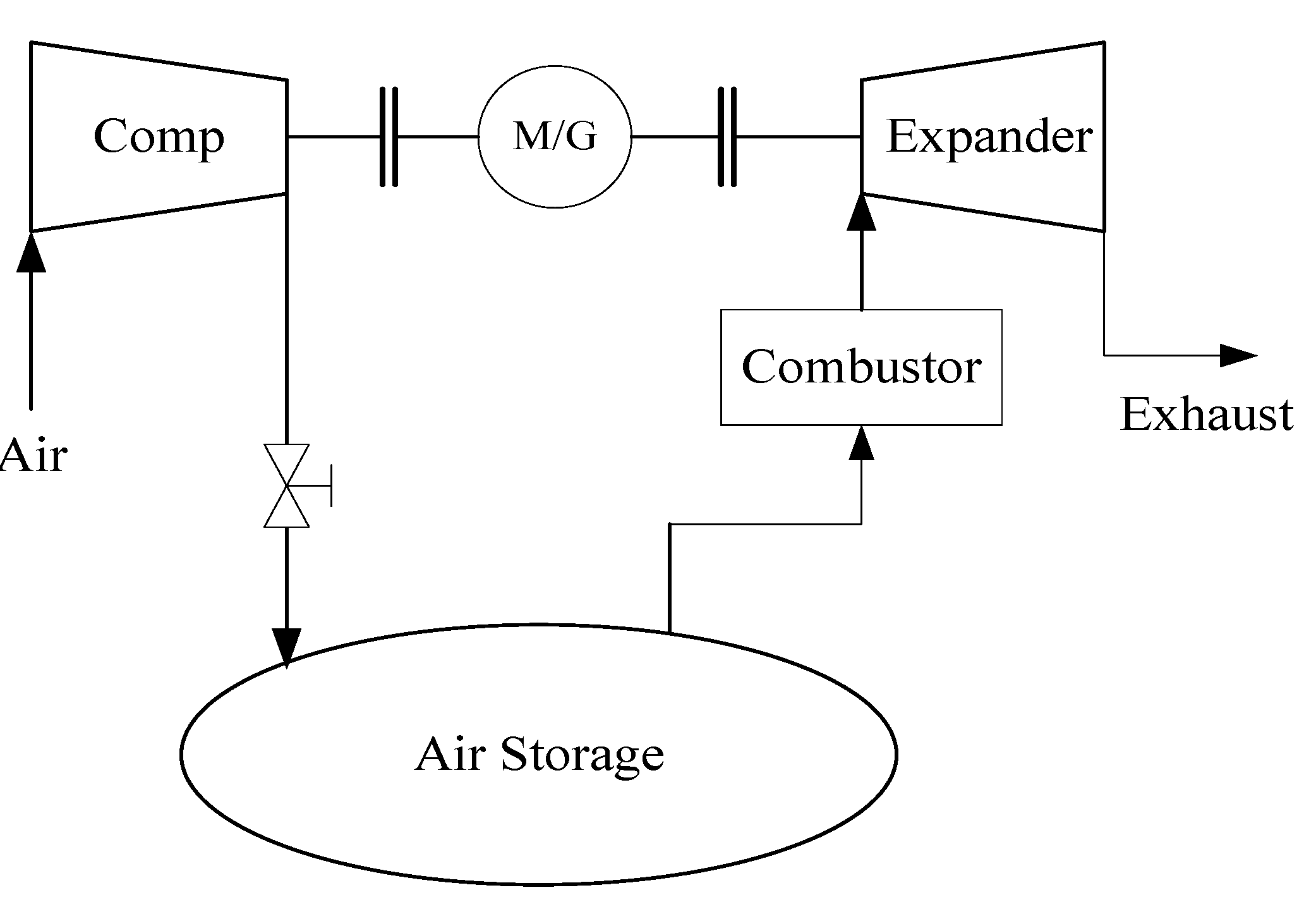
2.1.1. The First-Generation CAES System

The first-generation CAES system, given its practicality and similarity to a gas turbine power plant, was first used commercially about 36 years ago. In this system, air is compressed by a motor using low-cost and off-peak electricity. This compressed air is then stored in either underground caverns or in porous media. Subsequently, the pressurized air is released from the ground prior to mixing and burning with gas in a combustor. During peak demand periods, the hot gas drives a turbo expander and activates a generator, which in turn produces electricity. The compressor series and gas turbine are linked to the motor and the generator, respectively, by clusters. The conceptual diagram of this system is shown in Figure 1.
Figure 1. Conceptual diagram of the first-generation compressed air energy storage (CAES) power plant.
Energies 07 04988 g001

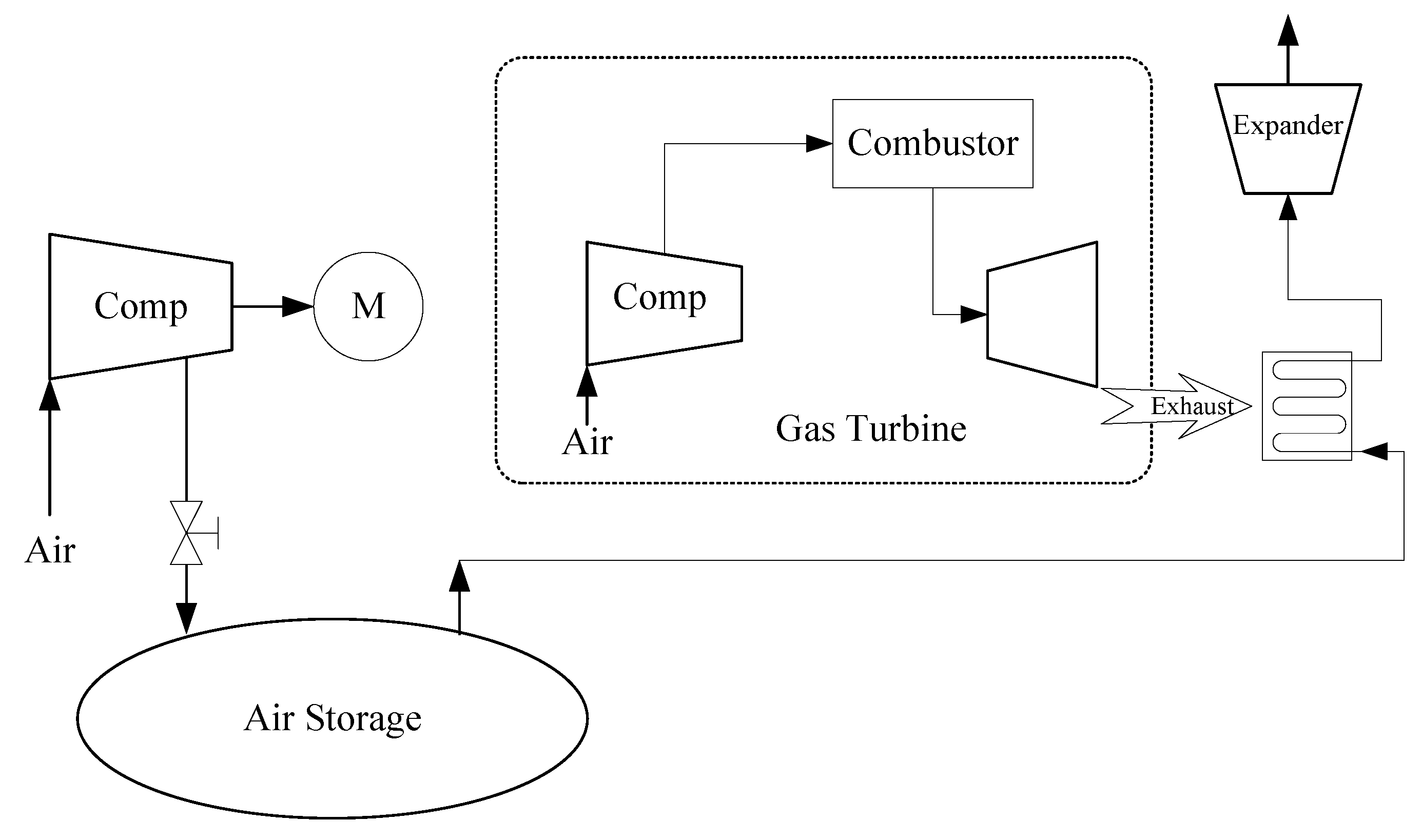
2.1.2. The Second-Generation CAES System

The second-generation CAES system is similar to its first-generation embodiment [13]. Figure 2 depicts a typical configuration of the second-generation CAES technology, which utilizes standard industry-proven equipment component to develop a reliable and economic CAES plant. In this system, some gas turbine technologies have been improved, as shown by the lowered heat rate (HR) and enhanced overall efficiency (approximately 54% against the 48% to 50% efficiency of the first-generation CAES system). The second-generation CAES technology is an open cycle and uses a traditional gas turbine. The exhaust from the gas turbine preheats the compressed air from the caverns.
Figure 2. Diagram of the second-generation CAES system.
Energies 07 04988 g002

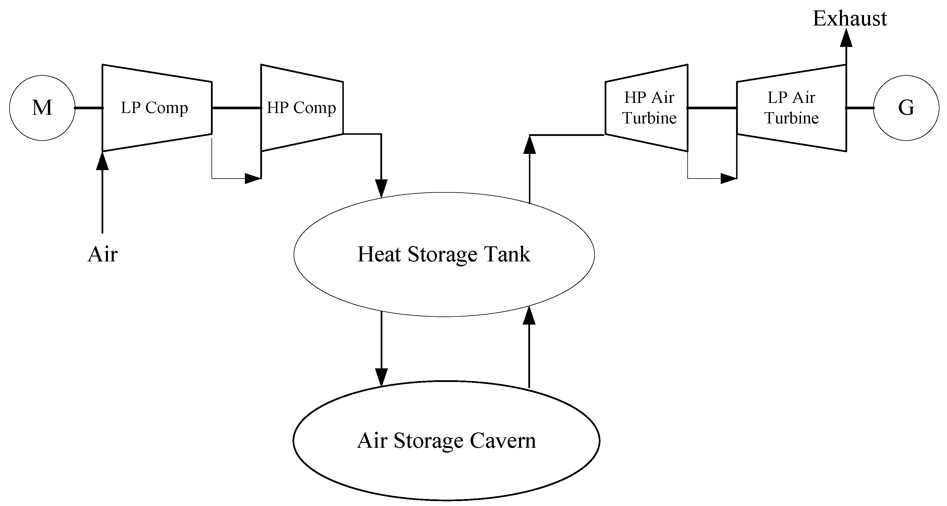
2.1.3. The Third-Generation CAES System

The third-generation CAES technology is also known as AA-CAES [14]. The typical configuration of this technology is presented in Figure 3 and also utilizes standard industry-proven equipment components. Key components include motor-driven compressors, thermal oil, a heat exchanger, and air expanders, all of which come with commercial guarantees and warranties. AA-CAES units do not use fuel to convert compressed air in storage into peak electricity power. Instead, thermal energy storage cools down the air in the compression phase and heats the stored air for power production. In storage operations, “cold oil” inter-cools the compressed air and generates “hot oil” for power production. This “hot oil” then heats the air from storage reservoir before the compressed air enters the expander for power production. The overall efficiency of electricity conversion from off-peak to on-peak varied from 70% to 75% [24]. However, thermal energy storage is the main problem of the third-generation CAES system, which is currently under investigation. The novel material used in thermal energy storage is high-temperature molten salt, which is also utilized to concentrate solar power.
Figure 3. Diagram of the third-generation CAES system.
Energies 07 04988 g003

2.2. Structure of Energy Sources and Technology Characteristics in China

2.2.1. Structure of Fossil Energy Sources in China

The distribution of energy sources and industry is extremely uneven in China. Statistics show that coal and NG reserves in China amount to 5.6 trillion tons and 50 trillion m3, respectively. In the western and northern regions of China, the structure of coal reserves is rich, whereas that in the eastern and southern regions is poor [25,26]. Coal reserves are mainly concentrated in undeveloped provinces, such as Shanxi, Inner Mongolia, Shaanxi, Xinjiang, Guizhou, and Ningxia. The coal reserves in these areas amount to approximately 4.63 trillion tons and constitute approximately 82.8% of the total reserves in the nation. In such coal-rich regions, the coal is readily available and of good quality. However, the southeast coast, eastern region and some prosperous cities are industrially developed but lack of energy sources. Only approximately 5.3% of the total reserves in the nation are found in Beijing, Shanghai, Tianjin, Shandong, Hebei, Liaoning, Jiangsu, Zhejiang, Guangdong, Fujian, Guangxi, Hainan, Hong Kong, and Taiwan. Nature gas (NG) reserves are abundant in the northwest and southwest areas of China [27], and 80% of the national NG reserves are concentrated in the Ordos Basin and the Sichuan Basin, the Tarim Basin, Tu-Ha Basin, and Zhungeer Basin in the autonomous region of Xinjiang Uygur, the Chadamu Basin in the Qinghai Province, the Eastern-Sea Basin, and the Yunnan–Guizhou region.

2.2.2. Geographical Situation of Wind Energy, Power Load and Water Resource in China

Rich sources of wind energy are mainly located in the northern and the southeastern coastal areas, as well as their adjacent islands. However, the geographical distribution of wind energy sources does not match the power load profile of the country. Areas with heavy power loads are concentrated in the economic centers along the coastal provinces in the east, in which sources of inland wind are scarce. However, in the northern regions, wherein wind sources are abundant, the power loads are light and the grid infrastructure is weak. The asynchrony between economic development and wind energy amplifies the present imbalance of wind power production and consumption.
Regions rich in water resources are mainly situated in southern China [28]. A boundary line is drawn by the Kunlun Mountain, Qinling Mountain, and Dabie Mountain, and the areas north of this boundary line have limited water resources. 17 northern provinces (including cities and autonomous regions) provide 21.4% of annual national water resources at 600.8 billion m3. In northern China, Taihang Mountain is the boundary line. Eastern regions are also richer in water resources than western regions. For instance, Shanxi, Gansu, and Ningxia provide only 7.5% of water resources in the north. In these three provinces (autonomous regions) and their adjacent provinces (Shaanxi, Inner Mongolia, and Xinjiang), rainfall quantity is below 500 mm, hence, resulting in a limited water resources.
As noted above, China’s resources distribution can be summarized as that the regions where energy sources are abundant are relatively undeveloped, whereas developed regions and power load centers are noticeably short in wind energy and water sources, and the regions rich in wind energy sources also possess much coal. As mentioned above, the wind power industry has developed fast in China. Nonetheless, wind-rich regions lack the proper hydrologic and geographic conditions to construct pumped hydro power plants for power grid peak shaving. Therefore, numerous CAES power plants must be built in west China.
Based on the analyses above, we believe that the following factors should be considered in the development of CAES in China: (1) the increased utilization of coal as fuel. China is rich in coal and deficient in NG. Thus, coal should be the main source of energy in China given the current distribution of energy sources. Moreover, Coal is also relatively lower in cost than NG. (2) The large capacity to level peak and off-peak power. The power grid and the wind power generation integrated to the power grid in China are extremely large. Only large CAES capacity can have access to level peak and off-peak power. (3) Relatively proven technology with simple structures. The industry base is poor overall in China as a developing country, and its economic support is limited. Given the current situation, a hybrid-fuel CAES system should be established.

2.3. Design of the Hybrid-Fuel CAES System

In consideration of the situation in China as discussed above, a hybrid-fuel CAES system is proposed. A conceptual configuration of the proposed CAES system is shown in Figure 4. It consists of an energy storage sub-system and an electricity-generation sub-system. In the energy storage stage, the compressors are driven by a motor that uses low-cost, off-peak electricity or remainder renewable energy power, and the air, compressed by the compressors, is stored either in underground caverns or in porous media, as in the first-generation CAES system. In the electricity generation stage, the pressurized air, released from the ground, is heated by a recuperator before flowing into the external combustion heater. The heated air released from the external combustion heater finally enters the high-pressure air turbine. After expanding in the air turbine, the air is piped to the external combustion heater for reheating, and then the heated air is mixing and burning with NG in the combustor. Finally, the resultant hot gases are used to drive the low-pressure gas turbine. Subsequently, the high-pressure air turbine and low-pressure gas turbine are linked to a generator to produce electricity during peak demand periods.
Figure 4. Flow sheet of the hybrid-fuel CAES system.
Energies 07 04988 g004
The energy storage sub-system is composed of a motor and a compression system. This compression system contains a coaxial compressor train with four stages. To achieve the lowest power consumption for the compression process, three intercoolers are arranged in the compression process. The compressed air is cooled down to 35 °C in the intercooler before entering the next stage of the compressor. After the air passes through the fourth compressor system, it is compressed to approximately 70 bar on average. Finally, the compressed air is injected into the cavern after cooling down to 35 °C by the aftercooler. In order to realize heat transfer, each output tube of the compressor is connected to the input tube of the corresponding cooler. Water is the cooling medium, and counter flow is adopted in the cooler. The heat generated in the compression process is carried away by the cooling water.
The sub-system that generates turbine electricity consists of an air turbine, a gas turbine, a combustor, a recuperator, a generator and an external combustion heater. During the peak power consumption periods, high-pressure air is released from the air room. This air is first preheated in the recuperator and absorbs heat from the exhaust of the gas turbine. The preheated air then passes through external combustion heater for further heating. The external combustion heater, using coal as fuel, is structurally similar to a heat-pipe hot blast stove. For safety considerations, the coal-combustion flue gas, whose temperature is over 1200 °C, is not allowed to transfer heat to the air directly. Therefore, a part of the external combustion heater exhaust is used to mix with the coal-combustion flue gas to decrease the gas temperature. And then the mixed flue gas, whose temperature is 800 °C, transfers the heat to the hot air. After the two-stage heating process, the heated air enters the air turbine to generate electricity. Thereafter, the air from the air turbine is reheated to 580 °C in the external combustion heater, and then the heated air with the adequately high pressure enters the combustion chamber along with high-pressure NG. Due to the fact that the pressure of NG in the NG transmission pipeline is about 40 bar, NG must be throttled to slightly above 19 bar before going into the combustor. The combustor output is linked to the gas turbine. By combustion, the gas is heated to 1200 °C before it enters the gas turbine. This turbine shares the axis of the air turbine to generate additional electricity. The gas turbine exhaust passes through the recuperator as the heat source of the cool compressed air and cools down to approximately 100 °C.
This proposed CAES design uses standard industry-proven equipment components to generate reliable and economic energy cycles from compressed air. All of the key components of the system come with commercial guarantees and warranties. The external combustion heater in the proposed CAES system is upgraded based on a heat-pipe hot blast stove. There are two tube bundles in the external combustion heater and counter flow is adopted. The air from the recuperator, with the temperature of 500 °C, flows through the high temperature zone of the external combustion heater, and the air from the air turbine flows through the low temperature zone. The heat-pipe hot blast stove is a widely utilized device with its thermal efficiency can reach to 75%–80% [29]. The highest output temperature of the air in a hot blast stove can even exceed 500 °C, therefore, with some optimization methods; the coal-fired boiler can satisfy the requirements of the hybrid-fuel CAES system. As the coal-fired boiler and the external combustion heaters are introduced into the CAES, aside from NG, coal constitutes more than 1/3 of the fuel for power generation. Thus, this hybrid-fuel CAES costs less and is more promising in consideration of China’s structure of energy sources.

3. Performance of the Hybrid-Fuel CAES System

3.1. Evaluation Criteria

The CAES plant has two different energy inputs (electric energy and fuel during the charging and discharging phases, respectively) given its dual purposes (peak power generation and energy storage). The evaluation criteria for CAES plants vary from those for conventional power plants. For instance, the thermodynamic merits of the CAES plant cannot be identified through specific fuel consumption, unlike in a conventional power cycle. Thus, new criteria are developed.

3.1.1. Energy Rate (ER)

ER is the ratio of the pumping energy in the off-peak period to the energy generated during the peak period:
Energies 07 04988 i001
However, this ER does not consider fuel consumption and is specific to CAES plants. Thereby, it is accompanied by Wt as a performance parameter, which denotes the net output of electric energy during the discharge phase.

3.1.2. HR

HR is expressed as the kW∙h of heat required to produce a kW∙h of energy:
Energies 07 04988 i002
where Qf is the total fuel energy (kW∙h) used in the combustors and the boilers during generation.

3.1.3. Overall Efficiency

The output from a CAES plant is work, and this output may be compared with the energy inputted into the plant, namely, NG and compressor operation [30]:
Energies 07 04988 i003
This equation may express storage efficiency; however, it is questionable because storage efficiency is represented by two different types of energy that are consumed by various parts of the process at dissimilar points in time. Fuel is not a component of electricity storage; it merely heats the air that transitions to the turbine.

3.1.4. Efficiency of Electricity Storage

The efficiency of electric energy may be defined as follows [30]:
Energies 07 04988 i004
System efficiency ηsys is a measure of the thermal efficiency of the energy system, and its value depends on the system to which the CAES plant is applied. For either a coal-fired or a gas turbine power plant, the ηsys value is between 30% and 55%. In this study, the ηsys values of a coal-fired and a gas turbine power plant are 40% and 55% [31,32], respectively. Considering that the ratio of gas and coal is approximately 2:1, the total ηsys of the proposed hybrid-fuel system is set to 50%.

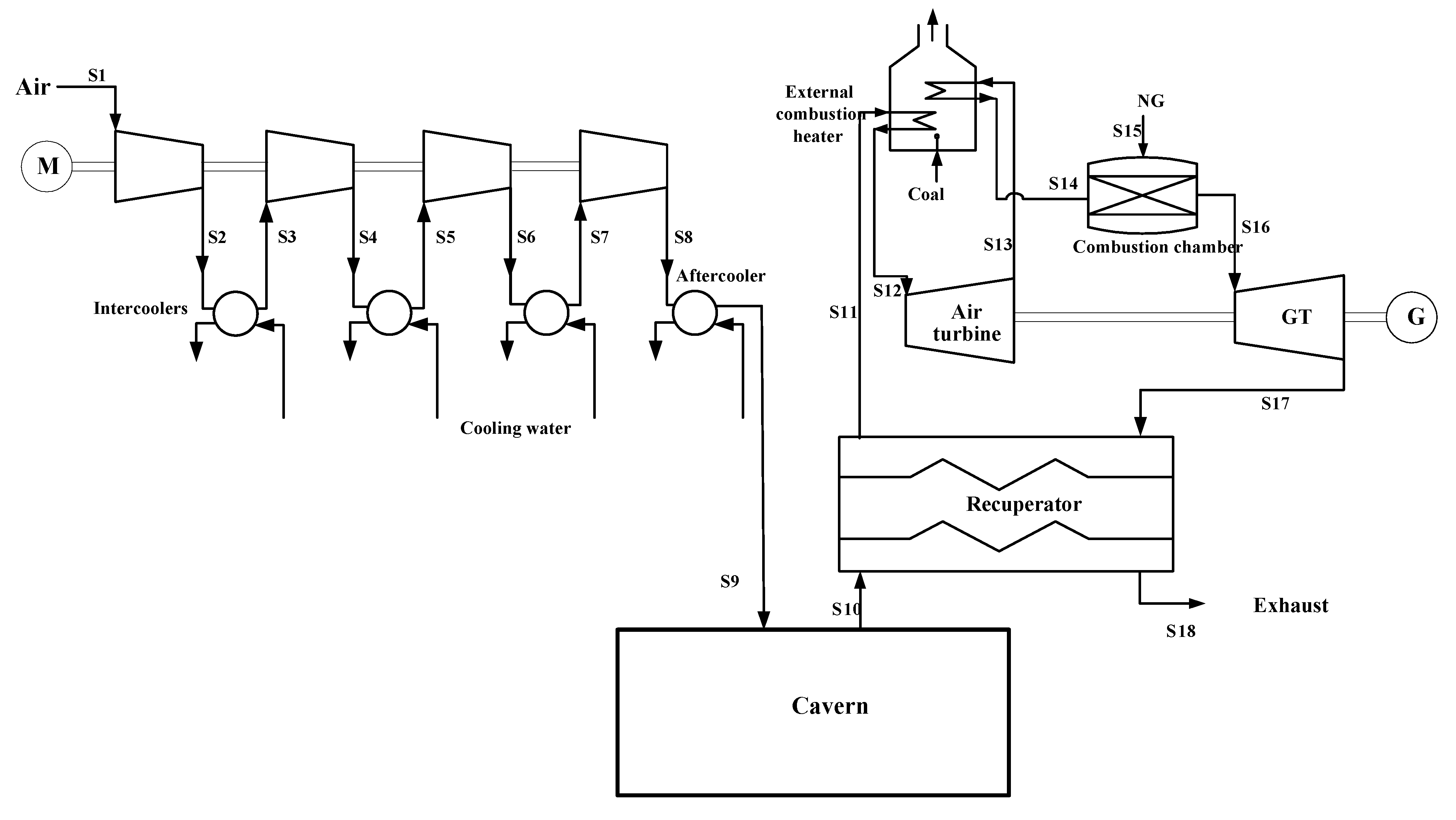
3.2. System Simulation

In the hybrid-fuel CAES system, the hot air in the external combustion heater is heated indirectly, so the final temperature of the air is limited. The inlet temperature of the air turbine in the proposed CAES is 540 °C, which is similar to that of the Huntorf plant. However, in consideration of the technological improvement of the gas turbine, the inlet temperature of the gas turbine is set to 1200 °C. The parameters of compressors in this paper are based on the data that Mortazavi et al. [33] chose for their simulation model. The parameters of turbines are selected with reference to existing data [34]. The total heat exchange capacity of the two external combustion heaters is approximately 114 MW, and the thermal efficiency of coal-fired boiler in this hybrid-fuel CAES is 0.8 based on a high-efficiency heat-pipe hot blast stove [29]. All the basic conditions and assumptions of the simulated system process are given in Table 1.
Table 1. Basic conditions and assumptions for simulation. LHV: lower heating value; and NG: natural gas.
CategoryParameterValue
Air and gas turbinesInlet temperature of air turbine (°C)540
Inlet temperature of gas turbine (°C)1,200
Pressure ratio of air turbine3
Pressure ratio of gas turbine18
Isentropic efficiency of air turbine (%)88.00
Isentropic efficiency of gas turbine (%)90.00
CompressorsNumber of stages4
Number of intercoolers3
Number of after-coolers1
Pressure ratio of each stage2.84–2.94
Average isentropic efficiency of compressors (%)86.00
Fuel informationLHV of coal (MJ/kg)29.31
LHV of NG (MJ/kg)50.03
Other assumptionsThermal efficiency of external combustion heater (%)80.00
Efficiency of generators (%)99.00
Efficiency of motors (%)99.00
Total hybrid-fuel ηsys (%)50.00
System efficiency ηsyscoal (%)40.00
System efficiency ηsysgas (%)55.00
Volume of the cavern (m3)400,000
Minimum pressure in the cavern (bar)65.18
Maximum pressure in the cavern (bar)74.62
Air throttling pressure from the cavern (bar)57.00
Operating timeContinuous operation time of the compressor (h)8
Continuous operation time of the turbine (h)2
The proposed CAES system is evaluated using the Aspen Plus commercial software. All of the state equations generated above for the simulated physical and chemical processes are calculated using the Peng-Robinson (P-R) base method. The P-R base method can compute all thermodynamic properties, except for the molar volume of liquid. This method is recommended for gas processing, oil refining, and chemical application because it can determine the thermodynamic properties of pure components. It is especially effective under high temperature and pressure; thus, critical regions can be computed reasonably. Moreover, the P-R equation can calculate the thermodynamic properties of gas mixtures, such as fugacity coefficient, density, enthalpy, entropy, and Gibbs free energy.
As the volume of the cavern in the hybrid-fuel CAES system is constant, the air pressure inside the cavern increases along with the compressed air injected continuously into the cavern in the low-load period. The procedure requires an amplitude variation in compressor outlet air pressure to effectively store air. Therefore, the compressor operates on continuously variable conditions in the compression process, and the pressure as well as the temperature of the streams in compression train is varying continuously. Considering the limitation of ASPEN PLUS, we analyze the thermodynamic characteristics of the hybrid-fuel CAES based on the average.
The discharge pressure of the cavern and the power output of the gas turbine both decrease as the compressed air is continuously discharged from the cavern in the load period. The gas turbine driven by sliding air pressure is not feasible due to the load characteristics in its supply network. Thus, the air from the cavern in this hybrid-fuel CAES is throttled down to 57 bar before it is fed into the combustion chamber, so the gas turbines operate under invariable conditions.
The pressure, temperature, mole flow, and composition of each stream corresponding to the points in Figure 4 are listed in Table 2. Noting that the streams from S2 to S9 are the average values in the compression process.
Table 2. Parameters of main points of the hybrid-fuel CAES system.
StreamsTemperature (°C)Pressure (bar)Mass flow (kg/s)Mole fraction (%)
N2O2CH4CO2H2O
S110.001.01102.0079.0021.000.000.000.00
S2124.792.90102.0079.0021.000.000.000.00
S335.002.90102.0079.0021.000.000.000.00
S4161.408.41102.0079.0021.000.000.000.00
S535.008.41102.0079.0021.000.000.000.00
S6161.7024.39102.0079.0021.000.000.000.00
S735.0024.39102.0079.0021.000.000.000.00
S8162.2570.73102.0079.0021.000.000.000.00
S935.0070.73102.0079.0021.000.000.000.00
S1050.0057.00400.0079.0021.000.000.000.00
S11500.8557.00400.0079.0021.000.000.000.00
S12540.0057.00400.0079.0021.000.000.000.00
S13359.1119.00400.0079.0021.000.000.000.00
S14580.0019.00400.0079.0021.000.000.000.00
S1550.0020.006.420.000.00100.00.000.00
S161,200.0419.00406.4276.7814.800.002.815.61
S17537.091.06406.4276.7814.800.002.815.61
S18100.001.06406.4276.7814.800.002.815.61

3.3. Performance Evaluation

The simulation results of the proposed CAES system are presented in Table 3. As indicated in Table 3, ER and HR are 0.50 and 1.13, respectively. These values suggest that to produce a kW∙h of energy, both the power consumed by compressors and the thermal energy required from fuel are relatively lower in the proposed CAES system than in the first-generation CAES system. The overall efficiency of the proposed CAES plant is also high at 61.18%. The high efficiency of electricity storage at 93.67% demonstrates that the proposed CAES system is efficient and effective.
Table 3. Simulation results of the hybrid-fuel CAES system. ER: energy rate; and HR: heat rate.
CategoryParameterValue
Fuel inputCoal input (MW)142.91
NG input (MW)321.19
Subtotal (MW)464.10
Power generationAir turbine (MW)79.54
Gas turbine (MW)329.72
Subtotal (MW)409.26
Internal power consumptionCompressors (MW)51.21
Subtotal (MW)51.21
Evaluation criteriaCoal/NG_ratio0.44
ER0.50
HR1.13
ηee61.18%
ηes93.67%
A comparison between the hybrid-fuel CAES and three generations of CAES technologies can be seen in Table 4. As shown in Table 4, the hybrid-fuel CAES has the lowest ER of the four CAES systems; this is attributed mainly to the efficiency improvement of both the compressor and gas turbine. Moreover, in the hybrid-fuel CAES, the compressed air is preheated in the external combustion heater before entering the combustion chamber. Assuming that the inlet air flow and outlet gas temperature of the combustion chamber keep unchanged, as the inlet air temperature of the combustion chamber increases, the amount of NG required for burning will decrease, thus, given the same power generation, the proposed hybrid-fuel CAES has a less NG consumption than other CAES. From this perspective, we believe that in most areas of northern China, in which is poor in NG but rich in coal, the hybrid-fuel CAES has far reaching application potential in electric energy storage and peak load shaving.
Table 4. Comparisons of the main parameters of hybrid-fuel CAES and other CAES systems. For the second-generation, the CAES plant power, based on a 172 MW Fr 7FA gas turbine with air injection for power augmentation, is rated at 420 MW net output.
NameThe first-generation CAES [10]The second-generation CAES [13]The third-generation CAES [35]Hybrid-fuel CAES
LocationHuntorf, GermanyNo practical plantNo practical plantNo practical plant
Output290 MW (about 2 h)420 MW114.5 MW410 MW
Compressor power60 MW (about 8 h)71 MW157.6 MW52 MW
Commission date1,978---
Pressure tolerance50–70 bar---
HR1.6 kW∙h/kW∙h1.08–1.11 kW∙h/kW∙h01.13 kW∙h/kW∙h
Cavern capacity310,000 m3--Assumed 400,000 m3
Energy ratio0.82 kW∙h/kW∙h0.70–0.75 kW∙h/kW∙h0.727 kW∙h/kW∙h0.50 kW∙h/kW∙h
FuelNGNGNo fuelCoal and NG

4. Discussion

4.1. Exergy Analysis

To determine the internal phenomena of the hybrid-fuel CAES system, exergy analysis is conducted [36]. The general exergy balance of each component of the CAES system can be expressed by the following rate form:
ΔEX = ∑EX(in) + ∑WX(in) − ∑EX(out) − ∑W(out)
where EX(in) and W(in) refer to the exergy input and the power input, respectively; EX(out) and W(out) denote the exergy output and the power output, respectively. The CAES systems are divided into several parts to conduct a detailed study on the exergy analysis. And the exergy analysis of all the equipment mentioned in this article is conducted according to the general exergy balance equation. Table 5 lists the exergy destruction of different system components.
Table 5. Expression of exergy destruction in the main components of the system.
ComponentsSchematic viewExergy destruction
Compressor Energies 07 04988 i005ΔEX(Com) = EX(1) + WEX(2)
Cooler Energies 07 04988 i006ΔEX(Co) = EX(1) + EX(3)EX(2)EX(4)
Storage cavern Energies 07 04988 i007ΔEX(SC) = EX(1)EX(2)
Combustion chamber Energies 07 04988 i008ΔEX(CC) = EX(1) + EX(2)EX(3)
Recuperator or heat exchanger Energies 07 04988 i009ΔEX(Re) = EX(1) + EX(3)EX(2)EX(4)
ΔEX(HE) = EX(1) + EX(3)EX(2)EX(4)
Turbine Energies 07 04988 i010ΔEX(T) = EX(1)EX(2)W
External combustion heater Energies 07 04988 i011ΔEX(ECH) = EX(1) + EX(3) + EX(5)EX(2)EX(4)EX(6)
The exergy of air or gas stream can be expressed as:
EX = (HH0) − T0(SS0)
where H and S are enthalpy and entropy of the steam, respectively; and the subscript 0 indicates that the properties are taken at the environmental temperature and pressure (T0 = 25 °C, P0 = 101 kPa). Therefore, the exergy input of air can be calculated with the initial parameters shown in Table 2.
To improve the compressor and gas turbine units and to enhance the suitability of the proposed CAES system for the actual conditions in China, we modified the pressure ratio, air flow, and inlet temperature of the turbine in the proposed system according to those of the Huntorf plant. The existing Huntorf CAES plant is selected as reference case in this paper. Considering the charge process and discharge process are not synchronous, and the compressor operates on variable conditions in the 8-h charge process, we conduct the exergy analysis on a 10-h cycle of the operation of the two systems. The analysis results are provided in Table 6. As shown in Table 6, the exergy efficiency of the proposed system is 59.84%, which is approximately 20% higher than that of the first-generation Huntorf CAES system at 40.46%. The result confirms the effectiveness of the proposed system compared with the conventional CAES systems.
Table 6. Exergy analysis of the hybrid-fuel CAES system.
CategoryHybrid-fuel CAES systemHuntorf CAES system
Value (MW∙h)Proportion (%)Value (MW∙h)Proportion (%)
Exergy inputAir1.870.141.980.14
Power consumption by compressors409.7129.95463.2231.71
Thermal energy input of coal285.8120.90--
Thermal energy input of NG670.4449.01995.5468.15
Subtotal1,367.84100.001,460.75100.00
Exergy outputGeneration of electricity power818.5259.84590.9740.46
Exergy destructionSub-system of energy storageCompressors40.983.0063.954.38
Coolers72.505.3097.456.67
Air storage room20.381.4935.782.45
Subtotal133.869.79197.1813.50
Sub-system of electricity generationHigh-pressure turbine10.440.7618.311.25
Low-pressure turbine28.352.0736.652.51
Recuperator19.921.46--
Subtotal58.714.2954.973.76
Combustion sub-systemExternal combustion heater148.5510.86--
Combustion chamber190.9413.96458.7231.40
Subtotal339.4924.82458.7231.40
Exergy of exhaust stream15.891.16153.2910.49
Total exergy output1,366.4899.901,455.1399.62
Error of exergy input and output (%)0.100.38
Exergy efficiency (%)59.8440.46
Exergy destruction is mainly induced by the combustion chamber, the external combustion heater, and the coolers in the sub-system of energy storage. The exergy destruction in the sub-system of turbine electricity generation in the proposed system was lower than that of the typical first-generation CAES system. This finding is mainly attributed to the following reasons: First, the inclusion of the recuperator significantly reduced the exergy destruction in the exhaust gas from the gas turbine. Second, the installation of external combustion heater, which is fuelled by coal, also contributed to the decreased exergy destruction; the exergy destruction in the combustion chamber is significantly higher in the typical first-generation CAES system. Third, the thermal energy derived from the coal enhanced the thermodynamic properties of the air to match the high parameters of the gas turbine (1200 °C); thus, the sub-system of power generation can generate more power.

4.2. Techno-Economic Analysis

4.2.1. Fundamental Parameters of a CAES Plant

Based on a typical CAES system, the hybrid-fuel CAES power plant can be analyzed. The volume of air storage required for a typical CAES plant is most economically provided by geological structures, such as salt caverns, aquifers, depleted oil, gas reservoirs, and rock mines. The cost of CAES investment is closely associated with the construction of air storage domes, the amount invested of Huntorf Plant (290 MW CAES) and McIntosh Plant (110 MW CAES) are $400/kW and $410/kW, respectively. And with the increase of the generating capacity, the total capital investment costs for 10 h air storage cavities range from $436/kW to $739/kW [9].
To configure a plant that optimizes the capability of the facility to capture market opportunities at any given location, standard compression blocks at 52 MW each can be combined with standard generation blocks at 410 MW each. The use of multi-unit trains on both the compression and generation sides maximizes the flexibility of the operator to manage the load, storage, and generated products of the CAES efficiently and cost-effectively. These multi-unit trains possess wide spans and respond quickly.
Therefore, the equipment used in this study was configured as follows:
Compression—a plant can operate under loads ranging from 26 MW to 52 MW given a 52 MW train. The load can be injected into storage.
Generation—a plant can operate under loads ranging from 205 MW to 410 MW. Loads can be withdrawn from storage.
Storage volume is optimally sized to allow a daily exchange of injected and withdrawn volumes. It is designed to accommodate a maximum of 10 h of rated injection into storage. The resultant generation, compression, and storage size of the CAES plant are 410 and 52 MW and 2050 MW∙h, respectively.
The overnight cost of above-ground equipment includes all costs of equipment, engineering, procurement and construction, spare parts, contingency, and interconnects for gas, air, water, and electricity. With a clutch, a generator can therefore be disconnected from the turbine to operate as a synchronous condenser. Cavern development costs include all of the costs associated with the acquisition of the land and mineral rights, the solution mining of the caverns, well-drilling and completion, and piping and casing.
Fixed operations and maintenance (FOM) cost includes expenses associated with start costs, including plant personnel and major maintenance accrual, and ancillary costs such as auxiliary power and water treatment. Variable operations and maintenance (VOM) cost mainly consists of accrual for major maintenance based on turbine utilization. The annual FOM and VOM costs are both assumed to be 2% of the total investment cost.
The fuel cost of the hybrid-fuel CAES includes NG cost and coal cost. The NG cost varies from place to place due to different gas sources and pipeline transportation conditions, for typical provinces located at the Three North area such as Gansu, Hebei, Shandong, and Harbin, their NG price is about $0.30/Nm3–$0.46/Nm3 [37]; While the coal cost varies because of different coal types, for example, the price of steam coal is approximately $46.2/ton–$107.7/ton, whereas the price of anthracite coal is about $138/ton–$184ton [38]. The annual off-peak electricity cost is related to the annual electricity generation and the local low price, peak and valley electric charges are widely adopted in the northwestern areas of China, taking Hebei Province as an example, the industrial electricity price at off-peak time is $25.8/MW∙h–$46.2/MW∙h [39]. Considering that either low-cost off-peak electricity from the grid or discarded wind energy meets the compression requirements, the price of off-peak electricity is assumed to be $30.77/MW∙h.
Table 7 summarizes the main assumptions regarding the 410 MW CAES plant. The prices of NG and coal and off-peak electricity apply to the electricity system in North China, where are suitable for developing the hybrid-fuel CAES. The $/¥ rate used in this paper is 6.5.
Table 7. Fundamental parameters of the hybrid-fuel 410 MW CAES plant. VOM: variable operations and maintenance; and FOM: fixed operations and maintenance.
NameValue and unitNameValue and unit
Generation range per unit205–410 MWOvernight cost—above ground equipment$500/kW
Compression range per unit26–52 MWOvernight cost—cavern development$100/kW
Cavern storage capacity2,050 MW∙hTotal overnight cost$600/kW
ER (kW∙h in/(kW∙h out)0.50Annual VOM cost2% of total investment cost
HR (kW∙h in/(kW∙h out)1.13Annual FOM cost2% of total investment cost
LHV of NG36 MJ/Nm3Price of NG$0.38/N∙m3
LHV of coal29.31 MJ/kgPrice of coal$123.08/ton
Equivalent base-load time1,200 hPrice of off-peak electricity$30.77/MW∙h

4.2.2. Economic Data

The levelized cost of electricity (COE) for a power plant is difficult to calculate [40]. Based on the assumption that the costs of energy production and of operation and maintenance are similar annually, the simplified expression for COE calculation can be described as:
COE = [(CRF)(Total investment cost) + (Annual O & M cost) + AFC + AOEC]/Annual on-peak electricity output
where AOEC denotes annual off-peak electricity cost; AFC refers to annual fuel cost; COE represents the levelized cost of electricity ($/kW∙h); and CRF denotes the capital recovery factor, which is related to the discounted rate (k) and equipment life. CRF is computed as:
CRF = [k∙(1 + k)n]/[(1 + k)n − 1]
The generation cost of a CAES system can be calculated in relation to the data shown in Table 7. The costs of NG and coal are computed according to the LHVs and HRs of NG and coal. The related data are exhibited in Table 8. As indicated in Table 8, the hybrid-fuel CAES model computes a COE of $131.07/MW∙h. In consideration that there is no CAES plant built in China currently, the techno-economic analysis is conduct based on a comparison of gas-fuel CAES and the hybrid-fuel CAES. The gas-fuel CAES has no external combustion heater but introduces two combustion chambers to produce high-temperature gas for turbines. And only NG is used as the fuel of the gas-fuel CAES. The other devices in the two CAES systems are identical in structure and parameter. As the thermal efficiency of combustion chamber is higher than external combustion heater, the gas-fuel CAES requires less thermal energy for air heating process, thereby ER of the gas-fuel CAES is decreased. However, the COE of the gas-fuel CAES is $136.55/MW∙h, which is $5.48/MW∙h higher than that of the hybrid-fuel CAES. The increase in the COE of the gas-fuel CAES can be attributed to that NG price ($10.68/KJ) is higher than coal ($4.20/KJ).
Table 8. Economic data of the hybrid-fuel 410 MW CAES plant. AOEC: annual off-peak electricity cost; CRF: capital recovery factor; and COE: cost of electricity.
NameValue and unitNameValue and unit
Total investment cost$246 millionCRF0.12
NG fuel rate2.83 MJ/kW∙hNG cost$30.15/MW∙h
Coal fuel rate1.26 MJ/kW∙hCoal cost$5.28/MW∙h
Annual VOM cost$4.92 millionVOM cost$10/MW∙h
Annual FOM cost$4.92 millionFOM cost$10/MW∙h
AOEC$7.68 millionCost of off-peak electricity$15.61/MW∙h
Total electricity output of CAES annually4.92 × 105 MW∙hCOE$131.07/MW∙h
Price of off-peak electricity$30.77/MW∙h--

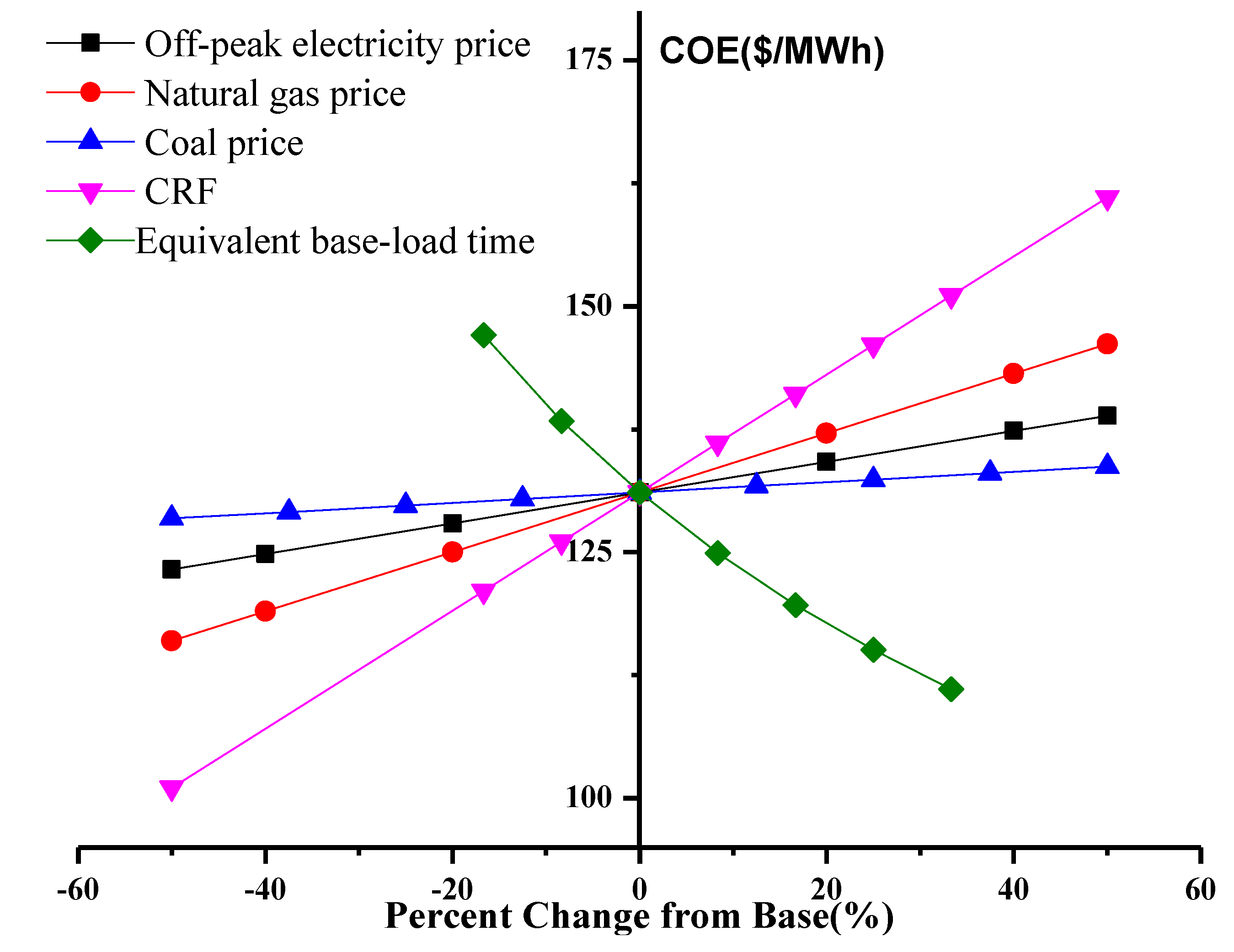
4.2.3. Sensitivity Analysis

Apart from Beijing and Tianjin (the municipalities directly under the Central Government), the price of on-peak electricity in North China is $107.69–$138.46/MW∙h [39]. Although the hybrid-fuel CAES, whose COE is $131.07/MW∙h, presents better economic performances compared to the gas-fuel CAES, it is still too expensive for grid integration if no additional incentives are taken for the implementation of the CAES system. In a competitive market, plant developers have no incentive to build generators to meet reserve requirements unless the market funds the average fixed costs (capital and operating costs) over the lifespan of the plant. Thus, the prices of off-peak energy, NG, coal, and CRF should be regarded as variables. The data obtained from sensitivity analysis are displayed in Figure 5, in which investment and VOM costs are fixed.
As shown in Figure 5, the equivalent base-load time has the most significant effects on the COE of the proposed CAES, and the price of coal has the slightest effects on the COE of the proposed CAES. In fact, when the location condition and grid condition of CAES vary, the price of off-peak electricity and NG will change considerably. The COE of the proposed CAES system ranges from $123.27/MW∙h to $138.88/MW∙h when the prices of off-peak energy range from $15.38/MW∙h to $46.15/MW∙h. The COE of the proposed CAES ranges from $115.98/MW∙h to $146.17/MW∙h when the NG price ranges from $0.19/Nm3 to $0.58/Nm3. Moreover, if the equivalent base-load time of CAES increases, the annual power generation will increase accordingly, which is beneficial to reducing the COE of CAES, as illustrated in Figure 5. When the equivalent base-load time climbs up to 1400 h, the COE of the proposed CAES dropped to below $120/MW∙h.
Figure 5. Sensitivity analysis of the COE of the hybrid-fuel CAES system.
Energies 07 04988 g005
The COE of the proposed CAES system varies due to different fuel supply conditions and grid conditions. The variation principles can be expressed as follows:
(1)
If the proposed CAES system is close to the gas source field, the NG cost is relatively low, which ensures the COE of CAES is relatively low;
(2)
If wind power takes a large proportion in the grid, part of the electric power required by the CAES charging process can be replaced by the power from wind curtailment, and then it is of great importance to reduce the COE of CAES;
(3)
When the peak valley fluctuations of the grid is rather large, indicating there is a huge load demand, then the annual peak-shaving power generation duration of CAES will be increased, as a result, the COE of CAES is reduced.
In conclusion, if the external environment condition in which CAES is located changes, the COE of CAES will fluctuate significantly. For example, the Ordos Basin areas in China contains plentiful NG, coal and wind resources, the COE of CAES located at these areas can be expected to reduce to about 100 $/MW∙h.

4.2.4. Further Discussion

The economic performance of the hybrid-fuel CAES is analyzed under the electricity market condition of North China Grid. The COE is estimated based on an average value of current data which are applied to the North China Grid. The results show that the hybrid-fuel CAES costs less than the gas-fuel CAES. However, without additional incentives, the hybrid-fuel CAES is still expensive for grid integration into North China Grid as the previous analysis. The main reasons for high COE can be summarized as: (1) there is no CAES plant built in China before, so the equipments of the CAES system are expensive under the current national conditions. Thus, building a new CAES plant in China would be rather expensive. (2) China is lack of NG resources, resulting in a high fuel cost of the CAES system.
However, it can be seen from the sensitivity analysis on COE of the proposed CAES system that COE is expected to drop significantly with the improvement in the fuel supply situations and electricity market conditions. Deduced from the current development trend, the hybrid-fuel CAES is likely to become competitive, concrete analysis is as follows:
(1)
The Chinese government encourages using NG as the fuel for electricity generation. More NG is being introduced from other countries, and more NG transmission engineering projects are carried out to improve the conditions of the NG transport [41]. The NG price is likely to fall predictably; it is beneficial to reduce the fuel cost of CAES.
(2)
More wind power will be connected to the power grids, bringing in a huge market space for CAES systems which contribute to balance grid wind power. There is a cost reduction in the charging process when CAES use the energy from wind curtailment to compress the air. Thus, the COE of CAES system is decreased accordingly.
(3)
The proposed CAES is similar with PHS systems in storing off-peak electricity or wind power. As the government regards CAES as an emerging strategic key industry [42], there should be a compensation mechanism based on the capacity of CAES, thus the price of electricity generated by CAES is expected to rise. The hybrid-fuel CAES power plant is competitive in the Chinese energy market if the on-peak energy price exceeds $153.85/MW∙h.
(4)
As mentioned above, the hybrid-fuel CAES, which use coal to replace part of NG, is more suitable for China’s conditions. If the hybrid-fuel CAES can be widely launched in China, more efforts and funds can be introduced to improve the equipment performance, which is bound to reduce the construction cost of CAES and improve the market competitiveness to CAES.
Besides, the proposed CAES system is helpful to accelerate the move to lower carbon generation in China. For the wind power centralized areas in China, peak-shaving methods with low carbon emissions such as pumped-storage is rarely adopted, thus leaving coal-fired power generating units as the only option. If CAES can be widely applied to wind power regulation, on the one hand, the coal-fired units used for wind power regulation can be reduced, which has significant effects on CO2 emissions reduction. For generating per kW∙h electricity, the standard coal consumed by CAES is about 43 g/kW∙h, which is much lower than that of the coal-fired power units (310–320 g/kW∙h), in turn realizing CO2 emissions reduction. On the other hand, large amounts of wind curtailment can be recycled, which is of great help to enhance the share of wind power in the grid, the wind power utilization rate is thus increased, again, this is beneficial to reduce the CO2 emissions of China.

5. Conclusions

In this study, a hybrid-fuel CAES system is proposed to address the energy situation in China. The hybrid-fuel CAES follows a typical CAES model to ensure the reliability and stability of the proposed system. Moreover, in this system, standard components of industry-proven equipment are used to generate reliable and economic cycles of compressed air. An external combustion heater, whose fuel is coal, is integrated to the proposed CAES to reduce the NG consumption of the system. The system performance of the hybrid-fuel CAES is derived and forecasted in theory, and exergy analysis and techno-economic analysis of the hybrid-fuel CAES are also conducted in the paper.
Due to the structure optimization of the CAES system and the performance improvement of the equipment, both ER and HR of CAES decrease significantly compared to the conventional first-generation CAES system. Thus, the overall efficiency of the hybrid-fuel CAES is reaching up to 61.18%. The results of the exergy analysis show that the hybrid-fuel CAES has an exergy efficiency of 59.84%, which is approximately 20% higher than that of the conventional first-generation CAES system. This advantage is mainly attributed to the inclusion of the process of heating from the exhaust gas, the installation of external combustion heaters, and the derivation of thermal energy from coal, which enhances the thermodynamic properties of the air to match the high parameters of the gas turbine (1200 °C).
The paper conducted a techno-economic analysis on the proposed CAES based on the electrical system in North China. Considering that CAES is a completely new system in China, where the lack of NG is an issue currently, the proposed CAES has no evident superior competition. However, if the given conditions such as NG were applied, large scale grid-connected wind power could be realized, and since technologies are continuously improving, the proposed CAES can be expected to have lower COE. Moreover, as the Chinese government is devoting efforts to supporting CAES, more preferential policies are likely to be implemented. Therefore, the proposed CAES system is simple, technically feasible, highly efficient, and could be helpful for CO2 emission reduction in China. Based on the current development tendency of China, CAES still possesses high market competiveness in the future. There should be broad application prospects for the proposed CAES to be developed in China.

Nomenclature

ER
Energy rate (kW∙h/kW∙h)
HR
Heat rate (kW∙h/kW∙h)
Wc
Compressor work (kW∙h)
Wt
Turbine work (kW∙h)
Qf
Total fuel energy (kW∙h)
LHV
Lower heating value (MJ/kg)
AOEC
Annual off-peak electricity cost ($)
CRF
Capital recovery factor
ηee
Overall efficiency
ηes
Efficiency of Electricity storage
ηsyscoal
System efficiency for coal-fired power plant
ηsys
System efficiency
ηsysgas
System efficiency for Gas turbine power plant
AFC
Annual fuel cost ($)
COE
Levelized cost of electricity ($/MW∙h)

Acknowledgments

The paper is supported by National Nature Science Fund of China (No. 51276059).

Author Contributions

In this paper, Wenyi Liu provides the original idea and constructs its framework, and is responsible for drafting and revising the whole paper; Linzhi Liu conducts the detailed calculation, simulation and contributes to revising the paper; Gang Xu and Yongping Yang are the main technical guidances and give some valuable comments on revising the paper; Feifei Liang devotes efforts to revising the paper; Weide Zhang completes the exergy analysis of the proposed system; and Ying Wu devotes efforts to the writing of the economic analysis of the proposed system.

Conflicts of Interest

The authors declare no conflict of interest.

References

  1. Liu, T.; Xu, G.; Cai, P.; Tian, L.; Huang, Q. Development forecast of renewable energy power generation in China and its influence on the GHG control strategy of the country. Renew. Energy 2011, 36, 1284–1292. [Google Scholar] [CrossRef]
  2. Working Group III of the Intergovernmental Panel on Climate Change (IPCC). IPCC’s Fourth Assessment Report (AR4): Mitigation of Climate Change; Cambridge University Press: Cambridge, UK, 2007. [Google Scholar]
  3. Lin, B.; Sun, C. Evaluating carbon dioxide emissions in international trade of China. Energy Policy 2010, 38, 613–621. [Google Scholar] [CrossRef]
  4. Hardisty, P.E.; Clark, T.S.; Hynes, R.G. Life cycle greenhouse gas emissions from electricity generation: A comparative analysis of Australian energy sources. Energies 2012, 5, 872–897. [Google Scholar] [CrossRef]
  5. Lee, A.H.; Lin, C.Y.; Kang, H.Y.; Lee, W.H. An integrated performance evaluation model for the photovoltaics industry. Energies 2012, 5, 1271–1291. [Google Scholar] [CrossRef]
  6. Raju, M.; Kumar Khaitan, S. Modeling and simulation of compressed air storage in caverns: A case study of the Huntorf plant. Appl. Energy 2012, 89, 474–481. [Google Scholar] [CrossRef]
  7. Lerch, E. Storage of fluctuating wind energy. In Proceedings of the 2007 European Conference on Power Electronics and Applications, Aalborg, Denmark, 2–5 September 2007.
  8. Makarov, Y.V.; Nyeng, P.; Yang, B.; Ma, J.; DeSteese, J.G.; Hammerstorm, D.J.; Lu, S.; Viswanathan, V.V.; Miller, C.H. Wide-Area Energy Storage and Management System to Balance Intermittent Resources in the Booneville Power Administration and California ISO Control Areas; Pacific Northwest National Laboratory (PNNL): Richland, WA, USA, 2008. Available online: http://www.pnl.gov/main/publications/external/technical_reports/PNNL-17574.pdf (accessed on 18 March 2011).
  9. Desai, N.; Gonzalez, S.; Pemberton, D.J.; Rathjen, T.W. The Economic Impact of CAES on Wind in TX, OK, and NM; Ridge Energy Storage & Grid Services L.P.: Houston, TX, USA, 2005; pp. 71–88. [Google Scholar]
  10. Crotogino, F.; Mohmeyer, K.U.; Scharf, R. Huntorf CAES: More Than 20 Years of Successful Operation. In Proceedings of the Solution Mining Research Institute (SMRI) Spring Meeting, Orlando, FL, USA, 15–18 April 2001; pp. 351–357.
  11. Eckroad, S.; Gyuk, I. EPRI-DOE Handbook of Energy Storage for Transmission & Distribution Applications; Electric Power Research Institute, Inc. (EPRI): Palo Alto, CA, USA, 2003. [Google Scholar]
  12. Ibrahim, H.; Younès, R.; Ilinca, A.; Dimitrova, M.; Perron, J. Study and design of a hybrid wind–diesel-compressed air energy storage system for remote areas. Appl. Energy 2010, 87, 1749–1762. [Google Scholar] [CrossRef]
  13. De Biasi, V. New solutions for energy storage and smart grid load management. Gas Turbine World 2009, 39, 22–25. [Google Scholar]
  14. Bullough, C.; Gatzen, C.; Jakiel, C.; Koller, M.; Nowi, A.; Zunft, S. Advanced Adiabatic Compressed Air Energy Storage for the Integration of Wind Energy. In Proceedings of the European Wind Energy Conference (EWEC 2004), London, UK, 22–25 November 2004.
  15. Hessami, M.A.; Bowly, D.R. Economic feasibility and optimisation of an energy storage system for Portland Wind Farm (Victoria, Australia). Appl. Energy 2011, 88, 2755–2763. [Google Scholar] [CrossRef]
  16. Zafirakis, D.; Kaldellis, J.K. Economic evaluation of the dual mode CAES solution for increased wind energy contribution in autonomous island networks. Energy Policy 2009, 37, 1958–1969. [Google Scholar] [CrossRef]
  17. Kim, Y.M.; Favrat, D. Energy and exergy analysis of a micro-compressed air energy storage and air cycle heating and cooling system. Energy 2012, 35, 213–220. [Google Scholar] [CrossRef]
  18. Grazzini, G.; Milazzo, A. A thermodynamic analysis of multistage adiabatic CAES. Proc. IEEE 2012, 100, 461–472. [Google Scholar] [CrossRef]
  19. Salgi, G.; Lund, H. System behaviour of compressed-air energy-storage in Denmark with a high penetration of renewable energy sources. Appl. Energy 2008, 85, 182–189. [Google Scholar] [CrossRef]
  20. Kim, H.M.; Rutqvist, J.; Ryu, D.W.; Choi, B.H.; Sunwoo, C.; Song, W.K. Exploring the concept of compressed air energy storage (CAES) in lined rock caverns at shallow depth: A modeling study of air tightness and energy balance. Appl. Energy 2012, 92, 653–667. [Google Scholar] [CrossRef]
  21. Greenblatt, J.B.; Succar, S.; Denkenberger, D.C.; Williams, R.H.; Socolow, R.H. Baseload wind energy: Modeling the competition between gas turbines and compressed air energy storage for supplemental generation. Energy Policy 2007, 35, 1474–1492. [Google Scholar] [CrossRef]
  22. Ibrahim, H.; Ilinca, A.; Perron, J. Energy storage systems-characteristics and comparisons. Renew. Sustain. Energy Rev. 2008, 12, 1221–1250. [Google Scholar] [CrossRef]
  23. User:Joeldebo/Wind Power in the People’s Republic of China. Available online: https://en.wikipedia.org/wiki/User:Joeldebo/Wind_power_in_the_People%27s_Republic_of_China (accessed on 10 January 2012).
  24. Adiabatic CAES Concept. Available online: http://www.espcinc.com/caes_graph7.swf (accessed on 10 January 2012).
  25. 2010 Coal Resource of China. 2011. Available online: http://www.sxcoal.com/coal/2324065/articlenew.html (accessed on 10 January 2012). (In Chinese)
  26. A Survey of Coal Resource for Different Regions in China. Available online: http://www.coal.com.cn/?aspxerrorpath=/%20Coal_Resource_1_070307040706_.htm (accessed on 10 January 2012). (In Chinese)
  27. 2010–2030 Natural Gas Resource Potential Reserve Analysis in China. Available online: http://www.askci.com/freereports/2011/07/271559325678.shtml (accessed on 10 January 2012). (In Chinese)
  28. Liu, Y.M.; Su, H.; Liu, W. Current situation and future of water resources in China: Strategy of water resources management for the 21st century. Water Resour. Prot. 2001, 4, 13–15. (In Chinese) [Google Scholar]
  29. Pan, Y.K.; Wang, X.Z.; Liu, X.D. Modern Drying Technology; Chemical Industry Publishing House: Beijing, China, 2006; pp. 1395–1400. (In Chinese) [Google Scholar]
  30. Elmegaard, B.; Brix, W. Efficiency of Compressed Air Energy Storage. In Proceedings of the 24th International Conference on Efficiency, Cost, Optimization, Simulation and Environmental Impact of Energy Systems, Novi Sad, Serbia, 4–7 July 2011.
  31. Mao, J.X. The Road of High Efficiency Coal Power in China; ETH Zurich: Zurich, Switzerland, 2012. Available online: http://www.esc.ethz.ch/events/seminars/Mao.pdf (accessed on 15 May 2014).
  32. Najjar, Y.S.H. Efficient use of energy by utilizing gas turbine combined systems. Appl. Therm. Eng. 2001, 21, 407–438. [Google Scholar] [CrossRef]
  33. Mortazavi, A.; Somers, C.; Alabdulkarem, A.; Hwang, Y.; Radermacher, R. Enhancement of APCI cycle efficiency with absorption chillers. Energy 2010, 35, 3877–3882. [Google Scholar] [CrossRef]
  34. Moran, M.J.; Shapiro, H.N.; Boettner, D.D.; Bailey, M.B. Fundamentals of Engineering Thermodynamics; John Wiley & Sons: Hoboken, NJ, USA, 2010; pp. 235–266. [Google Scholar]
  35. De Biasi, V. Fundamental analyses to optimize adiabatic CAES plant efficiencies. Gas Turbine World 2009, 39, 26–28. [Google Scholar]
  36. Buffa, F.; Kemble, S.; Manfrida, G.; Milazzo, A. Exergy and exergoeconomic model of a ground-based CAES plant for peak-load energy production. Energies 2013, 6, 1050–1067. [Google Scholar] [CrossRef]
  37. Impact Analysis of Gas Price Regulation on Natural Gas Industrial Train. 2013. Available online: http://www.china5e.com/index.php?m=content&c=index&a=show&catid=13&id=841614 (accessed on 9 July 2014). (In Chinese)
  38. Handpicked Coal Price in China (140114). 2014. Available online: http://www.snctc.cn/XXFW/price/city/2014-01-14/8274.html (accessed on 9 July 2014). (In Chinese)
  39. Notice on Regulating the Electricity Price of Hebei Power Grid. 2012. Available online: http://www.sjz.gov.cn/col/1351127873930/2012/11/05/1352104664583.html (accessed on 9 July 2014). (In Chinese)
  40. Gu, Y.; McCalley, J.; Ni, M.; Bo, R. Economic modeling of compressed air energy storage. Energies 2013, 6, 2221–2241. [Google Scholar] [CrossRef]
  41. LNG Development in the Twelfth “Five-Year” Plan of China (2011–2015); National Development and Reform Commission: Beijing, China, 2010. (In Chinese)
  42. Key Products and Service Guidance Directory of Emerging Strategic Industries; National Development and Reform Commission: Beijing, China, 2013. (In Chinese)

