1. Introduction
Switching shunt capacitor banks is the most widespread method for the compensation of reactive power or for the stabilization of voltage for power quality reasons [
1,
2,
3,
4,
5,
6]. Circuit breakers are usually switched to adjust the reactive power capacity according to the load change. Capacitive switching is conducted with an almost daily frequency according to an inquiry performed by the CIGRE (International Council on Large Electric systems) Working Group 13.04 in 1999 [
7]. About 60% of all capacitor banks are switched up to 300 times a year, and an additional 30% are switched up to 700 times a year. Capacitor-switching transients have caused many problems for the past few years [
8,
9,
10,
11,
12,
13,
14]. Among these problems, the capacitors bearing switching overvoltage may be the most direct and severe one. Thus, studying the effect of capacitor-switching transients on capacitors is essential.
In China, some 220 kV power substations (especially in Hainan, an island in Southern China) or most 500 kV series compensation station do not directly offer power supply to the users, and their 10 kV busbars are not usually connected to the industry loads or the other loads. Substation transformer and reactive compensation equipment are connected to 10 kV busbars in most of these substations. According to the fault statistics report from Chongqing electric power corporation, the faults caused by 10 kV switching transients are always under the condition with no load or light loads. Thus, the condition of no load or light loads will be more severe to the safety of power system and equipment during the switching transients.
In a 10 kV ungrounded neutral system, switching shunt capacitor banks often caused severe insulation faults of shunt capacitor banks or dry type transformers in China in recent years [
15,
16]. For example, in our previous work on switching shunt capacitor banks and shunt reactors [
15,
16], 12 kV vacuum circuit breakers (VCBs) were used, and capacitor explosion occurred during our field experiments on switching 10 kV shunt capacitor banks using ordinary VCBs in Chongqing, China, as shown in
Figure 1. After checking the burnt capacitor body, we found that the failure was caused by a breakdown between the two terminals of the capacitors. Overvoltage was deemed as the main reason of this accident. Therefore, based on our previous study and experience in this field, in a 10 kV ungrounded system, we proposed that the VCBs with phase selection was a potential and alternative method to limit the overvoltage and overcurrent caused by switching shunt capacitor banks.
Figure 1.
An explosion involving switching 10 kV shunt capacitor banks with vacuum circuit breakers (VCBs). (a) Testing site; and (b) burnt capacitors.
Figure 1.
An explosion involving switching 10 kV shunt capacitor banks with vacuum circuit breakers (VCBs). (a) Testing site; and (b) burnt capacitors.
Even though the transient duration is usually very short, switching shunt capacitor banks produces harmful transients which can reduce the life of the devices [
17,
18]. Conventionally, pre-insertion resistors or inductors, and R-C snubber circuits, have been applied to limit the switching transients during opening or closing shunt capacitor banks [
19,
20]. These methods may have reduced or limited the switching overvoltage and transients to some extent. However, pre-insertion resistors will dissipate energy and release a large amount of heat, and the operation of pre-insertion inductors may cause electric sparks and bring about resonance. Pre-insertion resistors or inductors will also result in increasing equipment costs and may not provide appreciable transient reduction [
18,
21]. The method of R-C snubber circuits may bring about severe harmonic distortion [
21,
22]. Thus, an alternative, more economical, and effective approach to reduce and limit the switching overvoltage and transients is phase-controlled switching. The significant advantages of phase-controlled switching include limitation of closing inrush currents, suppression of switching overvoltages, lower rate of power equipment failures and less maintenance of frequently used circuit breakers [
17,
19,
23]. CIGRE Working Group A3-07 presented a series of studies on the development and application of VCBs with phase selection [
17,
24]. According to their statistical data, circuit breakers with phase selection have been widely used in 26.4–800 kV power systems, and about 64% of all circuit breakers with phase selection are applied to switch shunt capacitor banks. Many theoretical and simulation studies on the overvoltage and insulation failures caused by switching shunt capacitor banks have been reported [
25,
26,
27,
28]. However, only a few studies have been done on the comparison and application of ordinary and phase-controlled VCBs in substation by field tests. For this reason, field measurements of switching 10 kV shunt capacitor banks have been conducted with the use of both ordinary VCBs and phase-controlled VCBs to compare the opening overvoltage and closing current caused by 10 kV switching shunt capacitor banks.
The main contribution of this study is to investigate and demonstrate the potential effects and advantages of phase-controlled VCBs in 10 kV switching transients instead of 110 kV system, when compared with the ordinary VCBs. The rest of this paper is organized as follows. In
Section 2, the overvoltage and the overcurrent of switching 10 kV Y-connected shunt capacitor banks are analyzed by analytical method based on a simplified circuit. In
Section 3, a phase-selecting control strategy for VCBs to switch on or to switch off capacitor banks is proposed. In
Section 4, six typical cases of field experiments are compared and discussed. Lastly, the conclusion is presented in
Section 5.
2. Analytical Analysis
The analytical analysis of switching shunt capacitor banks is studied.
Figure 2a illustrates the switching shunt capacitor bank circuit for an ungrounded power system with Y-connected shunt capacitor banks.
Usa(
t),
Usb(
t), and
Usc(
t) are the power sources.
R is the internal resistance of source.
Ka,
Kb, and
Kc are the circuit breakers.
L is the series inductance, and
C are the shunt capacitor banks. In a 10 kV ungrounded neutral system, the typical values of these parameters are as follows:
Usa(
t) = 8.165sin(100π
t) kV,
Usb(
t) = 8.165sin(100π
t + 120°) kV,
Usc(
t) = 8.165sin(100π
t − 120°) kV,
R = 0.2 Ω,
C = 27.14 µF,
L = 9.90 mH. The reduced circuit in
Figure 2b can be obtained with the assumption of simultaneous switching on/off for the three-phase circuit breakers.
Figure 2.
Circuit of switching shunt capacitor banks. (a) Symmetrical three-phase circuit; and (b) reduced circuit.
Figure 2.
Circuit of switching shunt capacitor banks. (a) Symmetrical three-phase circuit; and (b) reduced circuit.
2.1. Closing Operation
According to the principle of Kirchhoff‘s voltage law and initial conditions, Equation (1) can be obtained as:
where
,
is the angular frequency of source,
is the closing phase angle, and
is the source voltage amplitude.
With
, the solutions for Equation (1) are given as follows:
where
U0 is the value of the initial capacitor voltage,
Ucm is the steady voltage of capacitor
,
, and
is the oscillation frequency. The amplitude of the closing current and voltage are given as:
where
is the steady current of capacitor banks
,
, and
Hz in the most serious case. Thus, the closing overvoltage is below 2.0
Ucm, and the closing current may reach 11
in the most serious case.
With
, the amplitude of the closing current and voltage are given in the same way as:
where
I0 is the value of the initial capacitor current. Therefore, closing at
significantly decreases the closing current by comparing Equation (7) with Equation (5).
2.2. Opening Operation
When the moving and static contacts are separated,
is almost equal to
because the arc voltage and inductance voltage are very low (
). The capacitor voltage will be maintained at
Usm after arc extinguishing if capacitor the discharge is ignored. The transient recovery voltage of the circuit breaker contacts will be as follows:
is equal to −2
Usm after half a cycle (
). If the dielectric recovery voltage is less than 2
Usm at this moment, the re-striking and subsequent high-frequency oscillation will occur. The high-frequency voltage and current of the capacitor are given as follows:
The overvoltage of the capacitor is equal to 3Usm at ic(t) initially crossing zero during high-frequency oscillation. In the same moment, the overvoltage of capacitor will be maintained at 3Usm if the arc extinguishes. After a half cycle, the transient recovery voltage of the contacts reaches 4Usm. If re-striking occurs again, the maximum value of Uc(t) will reach 5Usm. With this analogy, the overvoltage of the capacitor becomes 3 p.u., 5 p.u., 7 p.u., and so on.
It should be noted that, however, in practical switching operation, the switching operation time cannot be completely consistent because of the switching time scatter of three-phase vacuum breakers. In a 10 kV ungrounded system, shunt capacitor banks are always in Y-type ungrounded neutral in China; random non-simultaneously switching generally will result in a shift of the voltage of the neutral point of the capacitor banks, higher overvoltage and overcurrent on capacitors and circuit breakers, and more complicated oscillation [
29,
30]. In particular, the overvoltage and overcurrent of the last switching pole will be affected by the switching angle, delay time and line-to-line voltage of the other two phases [
29,
30]. Thus, in 10 kV ungrounded system, the phase-controlled switching method is proposed in this study to limit the overvoltage and transients.
3. Phase-Selecting Control Strategy for 10 kV Ungrounded Capacitor Banks
The structure of phase-controlled VCBs used in this experiment (MDS2B-12) is presented. As depicted in
Figure 3, the MDS2B-12 mainly consists of a separate three-pole permanent magnetic actuator VCB, a three-pole phase selection intelligent controller, a power supply, a potential transformer testing capacitance residual voltage, and a telecommunications system.
The strategies and processes of switching shunt capacitor banks based on the phase-controlled methodology are analyzed, as shown in
Figure 4 and
Figure 5. To reduce the closing inrush current for ungrounded shunt capacitor banks, the strategy for closing capacitor banks is to close the two phases while their phase voltages are equal and then to close the third phase while its phase voltage crosses zero (5 ms later than the above two phases).
Figure 4 shows the sequence of closing capacitor banks with phase selection. Taking the line voltage of phase A and phase B as reference, the breaker receives the closing signal at
t0, the breakers of phase A and phase B close at
tab, and the breaker of phase C closes at
tc.
tAd,
tBd, and
tCd are the closing delay times, respectively.
Figure 3.
Structure chart of phase-controlled VCBs (MDS2B-12).
Figure 3.
Structure chart of phase-controlled VCBs (MDS2B-12).
Figure 4.
Sequence of closing capacitor banks with phase selection.
Figure 4.
Sequence of closing capacitor banks with phase selection.
Figure 5.
Sequence of opening capacitor banks with phase selection.
Figure 5.
Sequence of opening capacitor banks with phase selection.
The breakers should start to open a little earlier than the phase current crosses zero to ensure sufficient circuit breaker fracture gap distance (Δ
tb as shown in
Figure 5). The strategy for opening capacitor banks is to open one phase and then to open the other two phases when the current of the first-pole-to-clear reaches zero (5 ms later than the first phase).
Figure 5 shows the sequence of opening capacitor banks with phase selection. The breaker receives the opening signal at
t0, the breaker of phase B opens at
tb, and breakers of phase A and phase C opens at
tac.
tAd,
tBd, and
tCd are the opening delay times, respectively.
tAo,
tBo, and
tCo are the times between the moving contact starting to move and the moment the moving and static contacts are completely separated.
4. Field Test Results and Discussion
The field test of 10 kV switching shunt capacitor banks is conducted on the 10 kV side of a 110 kV substation in Chongqing, China. The short circuit capacity for the 10 kV system is 245 MVA, and the system short circuit reactance is 0.45 Ω.
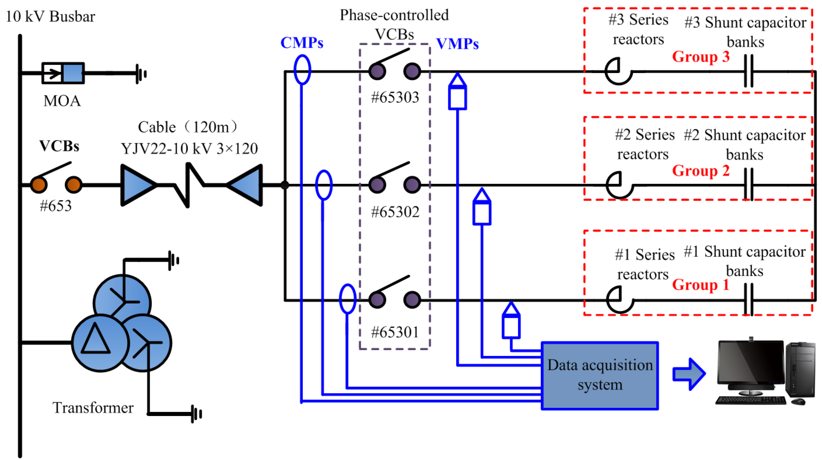
Figure 6 shows the site layout of the field experiment, and
Figure 7 presents the corresponding test circuit. #653 represents the ordinary VCBs, and #65301, #65302, and #65303 represent the three groups of phase-controlled VCBs, respectively. The layout of the voltage measurement points (VMPs) and the current measurement points (CMPs) in the field test are also shown in
Figure 7. The divider ratio of the capacitor voltage dividers is 350:1, and the frequency bandwidth of the capacitor dividers is from 50 Hz to 50 MHz. The current measurement range and the frequency bandwidth of the Rogowski coils are 0–6 kA and 30 Hz–1 MHz, respectively. The parameters of the capacitors and inductors are shown in
Table 1.
During the operation of ordinary VCBs and phase-controlled VCBs switching on and off the corresponding shunt capacitor banks, the signals from the Rogowski coils and capacitor voltage dividers are transferred to the signal processing unit. The signals are sampled and stored through a multichannel high-speed frequency conversion data acquisition card (maximum sampling frequency of up to 40 MHz) of a computer.
Figure 6.
Site layout of the field tests in a 110 kV substation.
Figure 6.
Site layout of the field tests in a 110 kV substation.
Figure 7.
Test circuit of switching 10 kV shunt capacitor banks in a 110 kV substation.
Figure 7.
Test circuit of switching 10 kV shunt capacitor banks in a 110 kV substation.
Table 1.
Parameters of the capacitors and reactors.
Table 1.
Parameters of the capacitors and reactors.
| Parameters | Phase A | Phase B | Phase C | Total |
|---|
| Power frequency | 50HZ | 50HZ | 50HZ | - |
| Rated power of capacitors | 2004 kVAR | 2004 kVAR | 2004 kVAR | 6012 kVAR |
| Number of capacitors | 6 | 6 | 6 | 18 |
| Number of groups | 3 | 3 | 3 | 9 |
| Number of capacitors in each group | 2 | 2 | 2 | 6 |
| Capacitance of each capacitor | 27.14 µF | 27.14 µF | 27.14 µF | - |
| Rated voltage of each capacitor | kV | kV | kV | - |
| Rated power of each capacitor | 334 kVAR | 334 kVAR | 334 kVAR | - |
| Series reactor rate of shunt capacitor bank | 5% | 5% | 5% | 5% |
| Rated power of reactors | 100.2 kVAR | 100.2 kVAR | 100.2 kVAR | 300.6 kVAR |
| Number of reactors | 3 | 3 | 3 | 9 |
| Number of groups | 3 | 3 | 3 | 9 |
| Number of reactors in each group | 1 | 1 | 1 | 3 |
| Inductance of each reactor | 9.90 mH | 9.90 mH | 9.90 mH | - |
| Rated voltage of each reactor | 10 kV | 10 kV | 10 kV | - |
| Rated power of each reactor | 33.4 kVAR | 33.4 kVAR | 33.4 kVAR | - |
| Quality factor (Q) of the reactor | 50 | 50 | 50 | - |
The switching of the shunt capacitor banks are conducted 10 times by using phase-controlled VCBs (#65301), and are conducted 12 times by ordinary VCBs (#653). The operation of opening shunt capacitor banks is implemented after 5 min of closing the shunt capacitor banks. However, the operation of closing is conducted after 10 min of opening the shunt capacitor banks to fully discharge the capacitor banks. Six different typical cases are analyzed and discussed, as shown in
Table 2 and
Figure 8,
Figure 9,
Figure 10,
Figure 11,
Figure 12 and
Figure 13. It should be noted that, in Cases 2 and 5, the three groups of capacitor banks are simultaneously switched. The main reason of these two cases is to make a comparison with Cases 1 and 4, in which the shunt capacitors are also switched by ordinary VCBs, to investigate the impact of capacitor compensation capacity on the switching overvoltage, overcurrent, and transient.
Table 2.
Typical cases of switching 10 kV shunt capacitor banks.
Table 2.
Typical cases of switching 10 kV shunt capacitor banks.
| No. | Operation | Breaker | Group | Voltage Base Value (kV) | Current Base Value (A) |
|---|
| Case 1 | Switching on | Without phase selection (#653) | 1 | 8.165 | 155.56 |
| Case 2 | Switching on | Without phase selection (#653) | 1–3 | 8.165 | 466.69 |
| Case 3 | Switching on | With phase selection (#65301) | 1 | 8.165 | 155.56 |
| Case 4 | Switching off | Without phase selection (#653) | 1 | 8.165 | 155.56 |
| Case 5 | Switching off | Without phase selection (#653) | 1–3 | 8.165 | 466.69 |
| Case 6 | Switching off | With phase selection (#65301) | 1 | 8.165 | 155.56 |
The peak line-to-neutral voltage of 10 kV power systems is as follows [
16,
31]:
4.1. Case 1
Before the switching-on operations in Case 1, #65302 and #65303 are opened, and #65301 is closed. The circuit breaker of this switching operation is #653.
Figure 8a shows the closing current waveform of Case 1 without phase selection. The maximum value of the closing current in this case occurs in phase B, and its value is 0.63 kA (4.04 p.u.). The duration of the closing shunt capacitor banks’ current transient is about 110–120 ms, and the high-frequency oscillation frequency of the closing shunt capacitor banks’ current is about 198 Hz.
Figure 8b illustrates corresponding closing voltage waveforms in Case 1. The maximum of the closing voltage is 10.08 kV (1.23 p.u.). The duration of the closing shunt capacitor banks’ voltage transient is only 20 ms.
Figure 8.
Waveforms of the closing current and capacitor voltage in Case 1. (a) Current waveform; and (b) voltage waveform.
Figure 8.
Waveforms of the closing current and capacitor voltage in Case 1. (a) Current waveform; and (b) voltage waveform.
4.2. Case 2
Before the switching-on operations in Case 2, #65301, #65302, and #65303 are all closed. The circuit breaker of this switching operation is also #653.
Figure 9a shows the closing current waveform in Case 2 without phase selection but with three groups of shunt capacitor banks. The maximum value of the closing current in this case occurs in phase A, and its value is − 2.09 kA (4.49 p.u.). The duration of the closing shunt capacitor banks’ current transient is about 90–100 ms, and the high-frequency oscillation frequency of the closing shunt capacitor banks’ current is about 192 Hz in this case.
Figure 9b illustrates the corresponding closing voltage waveforms in Case 2. The maximum of the closing voltage also occurs in phase A, and its value is 14.25 kV (1.75 p.u.). The voltage transient reaches the steady state after about 20 ms.
Figure 9.
Waveforms of the closing current and capacitor voltage in Case 2. (a) Current waveform; and (b) voltage waveform.
Figure 9.
Waveforms of the closing current and capacitor voltage in Case 2. (a) Current waveform; and (b) voltage waveform.
4.3. Case 3
Before the switching-on operations in Case 3, #653 is closed, and #65302 and #65303 are opened. The circuit breaker of this switching operation is #65301.
Figure 10a shows the closing current waveform in Case 3 with phase selection. The strategy of the closing shunt capacitor banks with phase selection is addressed in
Section 2. The maximum value of the closing current in this case occurs in phase A, and its value is 0.33 kA (2.12 p.u.). The duration of the closing shunt capacitor banks’ current transient is about 100–110 ms, and the high-frequency oscillation frequency of the closing shunt capacitor banks’ current is about 206 Hz in this case.
Figure 10b illustrates the corresponding closing voltage waveforms. As shown in
Figure 10b, phase A and phase B are closed at
t1 when their line voltage
Uab crosses zero, and then phase C is closed after 5 ms at
t2 when its phase voltage crosses zero. The transient voltage of phase C from
t1 to
t2 is equal to the neutral voltage of the shunt capacitor banks. Thus, the zero-crossing switching strategy is achieved. Almost no high-frequency voltage oscillation occurs in this case, and the corresponding maximum of the high-frequency oscillation voltage is very low (about 0.76 p.u.). The time error of the phase-controlled circuit breaker for closing the shunt capacitor banks is below ±0.2 ms.
4.4. Case 4
Before the switching-off operations in Case 4, #65302 and #65301 are opened, and #65301 is closed. The circuit breaker of the switching operation is #653.
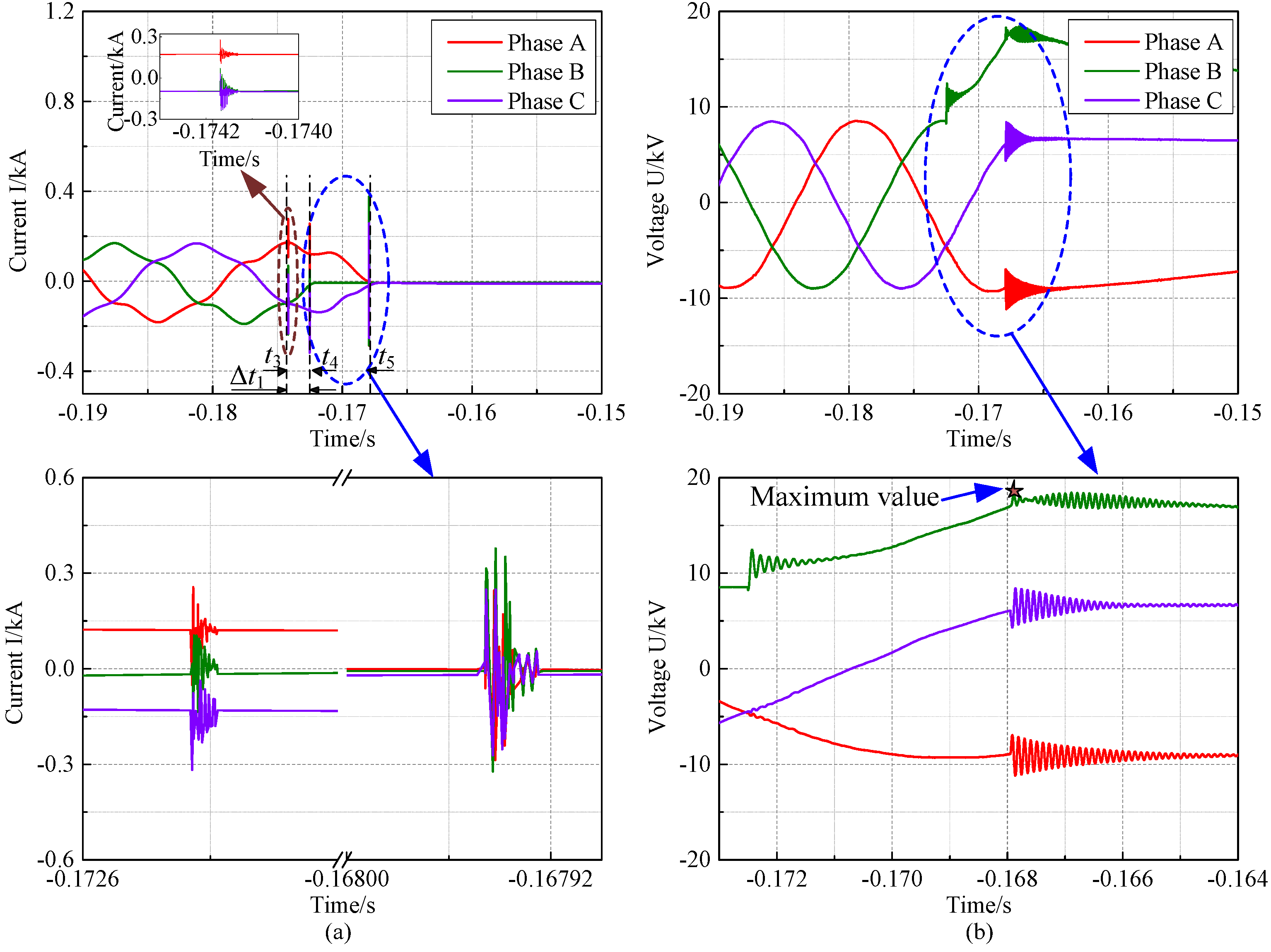
Figure 11a shows the opening current waveform in Case 4 without phase selection. The breaker contacts of phase B start to separate at
t3, and phase B is the first-pole-to-clear. The transient currents of phase A and phase C are always equal, but in the opposite direction, after the current of phase B decreases to zero at the moment of
t4, which is also the time of the contacts of phase A and phase C start to separate. The breaking arc duration of phase B is Δ
t1 = 1.7 ms (Δ
t1 =
t4 −
t3). After a quarter of a cycle (5 ms), the currents of phase A and phase C both reach zero at the moment of
t5. Thus, the phenomenon of the power frequency extinguishing arcing is observed. Statistical results according to our field tests show that the breaking arc duration of the first-pole-to-clear (phase B in this test) is almost 1.0–4.5 ms.
Figure 11b illustrates the corresponding opening voltage waveforms in Case 4. The maximum of the opening voltage in this case occurs in the first-pole-to-clear (phase B), and its value is 18.45 kV (2.26 p.u.). Residual charge of the capacitors remains more than 30 power frequency cycles after the capacitors are disconnected. Thus, the switching off operation is 10 min later.
Figure 10.
Waveforms of the closing current and capacitor voltage in Case 3. (a) Current waveform; and (b) voltage waveform.
Figure 10.
Waveforms of the closing current and capacitor voltage in Case 3. (a) Current waveform; and (b) voltage waveform.
Figure 11.
Waveforms of the opening current and capacitor voltage in Case 4. (a) Current waveform; and (b) voltage waveform.
Figure 11.
Waveforms of the opening current and capacitor voltage in Case 4. (a) Current waveform; and (b) voltage waveform.
4.5. Case 5
Before the switching-off operations in Case 5, #65301, #65302, and #65303 are all closed. The circuit breaker of this switching operation is still #653.
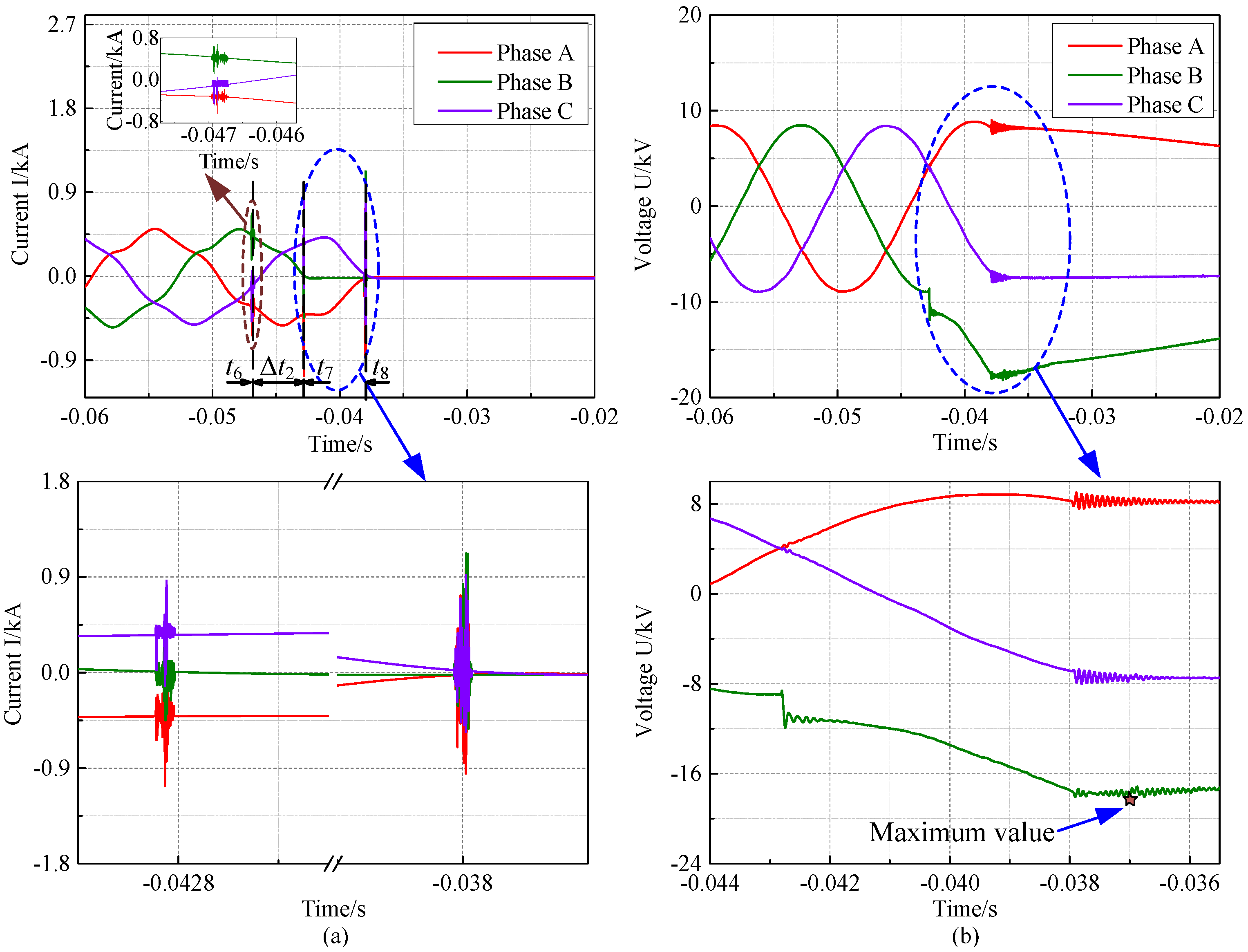
Figure 12a shows the opening shunt capacitors banks’ current waveform in Case 5 without phase selection but with three groups of shunt capacitor banks. The breaker contacts of phase B start to separate at
t6, and phase B is also the first-pole-to-clear. The breaking arc duration of phase B is Δ
t2 = 4.1 ms (Δ
t2 =
t7 −
t6). The currents of phases A and C are equal but opposite in direction from
t7 to
t8, during which the current of phase B reaches zero. After
t8, the currents of the three phases remain zero.
Figure 12b shows the opening voltage waveforms in Case 5. The maximum value of the opening voltage is − 18.20 kV (2.23 p.u.), and it still occurs in the first-pole-to-clear (phase B) in this case.
Figure 12.
Waveforms of the opening current and capacitor voltage in Case 5. (a) Current waveform; and (b) voltage waveform.
Figure 12.
Waveforms of the opening current and capacitor voltage in Case 5. (a) Current waveform; and (b) voltage waveform.
4.6. Case 6
Before the switching-off operations in Case 6, #653 is closed, and #65302 and #65303 are opened. The circuit breaker of this switching operation is #65301.
Figure 13a shows the opening current waveforms in Case 6 with phase selection. The strategy for opening shunt capacitor banks with phase selection is also addressed in
Section 2. The breaker contacts of phase B start to separate 2.67 ms (Δ
t3 = 2.67ms) later than its last current zero-crossing point at
t9, and phase B is the first-pole-to-clear. The transient currents of phase A and phase C are always equal, but in the opposite direction, after the current of phase B decreases to zero at the moment of
t10, which is also the time that the contacts of phase A and phase C start to separate. The breaking arc duration of phase B is Δ
t4 = 7.4 ms (Δ
t4 =
t10 −
t9). After a quarter of a cycle (5 ms), the currents of phase A and phase C both reach zero at the moment of
t11. Therefore, the power frequency extinguishing arcing still occurs in this case. Statistical results according to our field tests indicate that the breaking arc duration of the first-pole-to-clear (phase B in this test) is about 7.5 ms, and the time error of the phase-controlled circuit breaker for opening shunt capacitor banks is below ±0.3 ms.
Figure 13b illustrates the opening voltage waveform in Case 6. The maximum of the opening voltage in this case occurs in the first-pole-to-clear (phase B), and its value is − 12.83 kV (1.57 p.u.). The residual charge of capacitors remains more than 30 power frequency cycles after the capacitors are disconnected.
Figure 13.
Waveforms of the opening current and capacitor voltage in Case 6. (a) Current waveform; and (b) voltage waveform.
Figure 13.
Waveforms of the opening current and capacitor voltage in Case 6. (a) Current waveform; and (b) voltage waveform.


