
Magnetoelectric Properties of Multiferroic Composites Based on BaTiO3 and Nickel-Zinc Ferrite Material

 , , , , , , and
Abstract
:1. Introduction
2. Materials and Methods
2.1. Technology Process
2.2. Measurements Methods
3. Results and Discussion
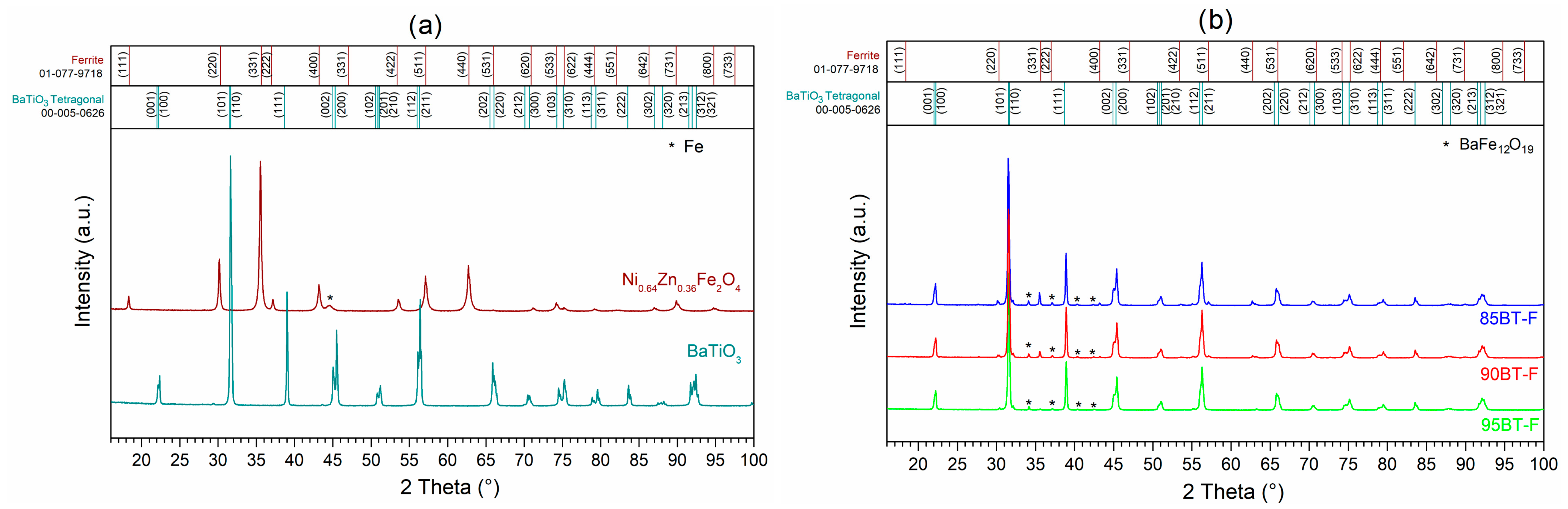
3.1. Crystal Structure
3.2. Microstructure
3.3. Dielectric Properties
3.4. DC Electric Conductivity
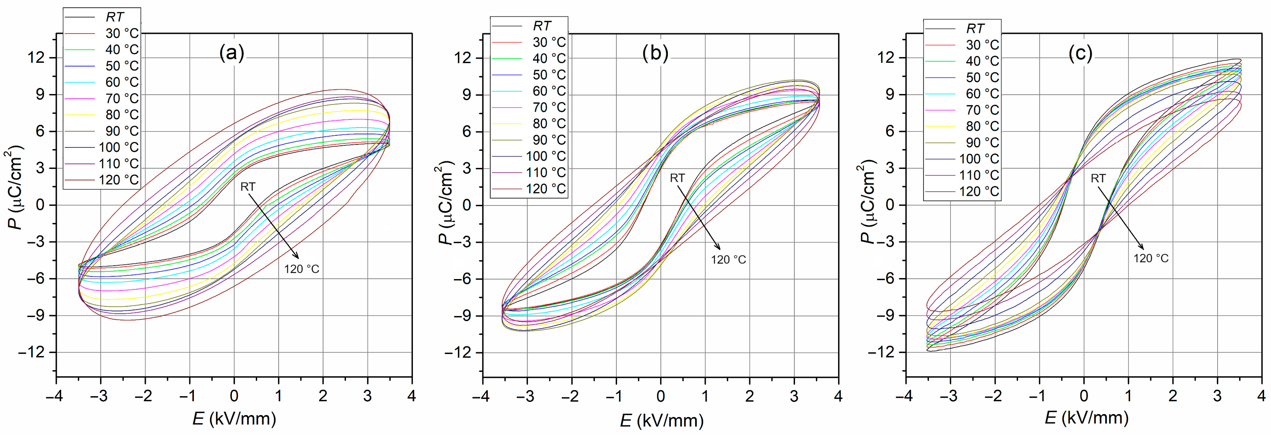
3.5. P–E Tests
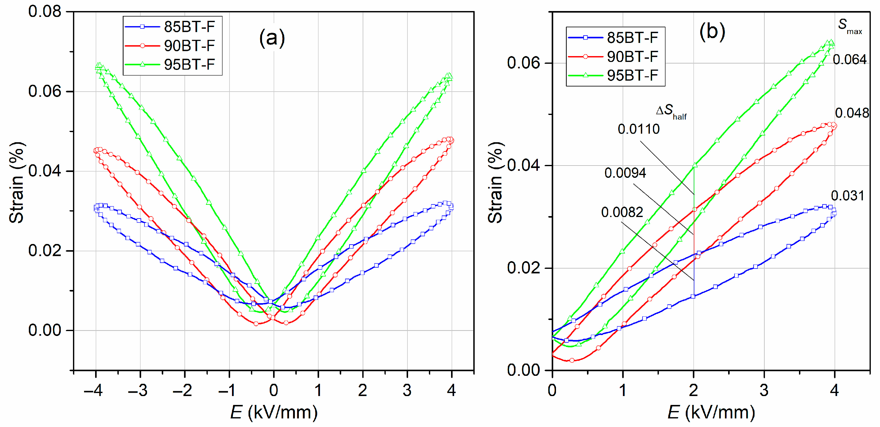
3.6. S-E Test
3.7. Piezoelectric Properties
3.8. Magnetic Properties
3.9. Magnetoelectric Properties
4. Conclusions
Supplementary Materials
Author Contributions
Funding
Institutional Review Board Statement
Informed Consent Statement
Data Availability Statement
Conflicts of Interest
References
- Rao, C.N.R.; Sundaresan, A.; Saha, R. Multiferroic and magnetoelectric oxides: The emerging scenario. J. Phys. Chem. Lett. 2012, 3, 2237–2246. [Google Scholar] [CrossRef] [PubMed]
- Fiebig, M. Revival of the magnetoelectric effect. J. Phys. D Appl. Phys. 2005, 38, R123–R152. [Google Scholar] [CrossRef]
- Chu, Y.H.; Martin, L.W.; Holcomb, M.B.; Ramesh, R. Controlling magnetism with multiferroics. Mater. Today 2007, 10, 16–23. [Google Scholar] [CrossRef]
- Eerenstein, W.; Mathur, N.D.; Scott, J.F. Multiferroic and magnetoelectric materials. Nature 2006, 442, 759–765. [Google Scholar] [CrossRef] [PubMed]
- Curecheriu, L.; Postolache, P.; Buscaglia, V.; Horchidan, N.; Alexe, M.; Mitoseriu, L. BaTiO3–ferrite composites with magnetocapacitance and hard/soft magnetic properties. Phase Transit. 2013, 86, 670–680. [Google Scholar] [CrossRef]
- Wang, K.F.; Liu, J.M.; Ren, Z.F. Multiferroicity: The coupling between magnetic and polarization orders. Adv. Phys. 2009, 58, 321. [Google Scholar] [CrossRef]
- Leung, C.M.; Li, J.; Viehland, D.; Zhuang, X. A review on applications of magnetoelectric composites: From heterostructural uncooled magnetic sensors, energy harvesters to highly efficient power converters. J. Phys. D Appl. Phys. 2018, 51, 263002. [Google Scholar] [CrossRef]
- Nan, C.W.; Bichurin, M.I.; Dong, S.; Viehland, D.; Srinivasan, G. Multiferroic magnetoelectric composites: Historical perspective, status, and future directions. J. Appl. Phys. 2008, 103, 031101. [Google Scholar] [CrossRef]
- Srinivasan, G. Magnetoelectric composites. Annu. Rev. Mater. Res. 2010, 40, 153–178. [Google Scholar] [CrossRef]
- Jedrecy, N.; Aghavnian, T.; Moussy, J.-B.; Magnan, H.; Stanescu, D.; Portier, X.; Arrio, M.-A.; Mocuta, C.; Vlad, A.; Belkhou, R.; et al. Cross-correlation between strain, ferroelectricity, and ferromagnetism in epitaxial multiferroic CoFe2O4/BaTiO3 heterostructures. ACS Appl. Mater. Interfaces 2018, 10, 28003–28014. [Google Scholar] [CrossRef]
- Vopson, M.M. Fundamentals of multiferroic materials and their possible applications. Crit. Rev. Solid State 2015, 40, 223. [Google Scholar] [CrossRef]
- Bichurin, M.; Petrov, V.; Priya, S.; Bhalla, A. Multiferroic magnetoelectric composites and their applications. Adv. Cond. Matter. Phys. 2012, 2012, 129794. [Google Scholar] [CrossRef]
- Hill, N.A. Why are there so few magnetic ferroelectrics? J. Phys. Chem. B 2000, 104, 6694–6709. [Google Scholar] [CrossRef]
- Zhai, J.; Xing, Z.; Dong, S.; Li, J.; Viehland, D. Magnetoelectric laminate composites: An overview. J. Am. Ceram. Soc. 2008, 91, 351–358. [Google Scholar] [CrossRef]
- Martin, L.W.; Crane, S.P.; Chu, Y.H.; Holcomb, M.B.; Gajek, M.; Huijben, M.; Yang, C.H.; Balke, N.; Ramesh, R. Multiferroics and magnetoelectrics: Thin films and nanostructures. J. Phys. Condens. Matter. 2008, 20, 434220. [Google Scholar] [CrossRef]
- Pachari, S.; Pratihar, S.K.; Nayak, B.B. Enhanced magneto-capacitance response in BaTiO3-ferrite composite systems. RSC Adv. 2015, 5, 105609–105617. [Google Scholar] [CrossRef]
- Pachari, S.; Pratihar, S.K.; Nayak, B.B. Improved magneto-capacitance response in combustion derived BaTiO3-(CoFe2O4/ZnFe2O4/Co0.5Zn0.5Fe2O4) composites. J. Alloy. Compd. 2019, 784, 897–905. [Google Scholar] [CrossRef]
- Khomskii, D. Classifying multiferroics: Mechanisms and effects. Physics 2009, 2, 20–27. [Google Scholar] [CrossRef]
- Tokuraand, Y.; Seki, S. Multiferroics with spiral spin orders. Adv. Mater. 2010, 22, 1554–1565. [Google Scholar] [CrossRef]
- Cheng, Y.; Peng, B.; Hu, Z.; Zhou, Z.; Liu, M. Recent development and status of magnetoelectric materials and devices. Phys. Lett. A 2018, 382, 3018–3025. [Google Scholar] [CrossRef]
- Niemiec, P.; Bartkowska, J.A.; Brzezinska, D.; Dercz, G.; Stoklosa, Z. Electrophysical properties of the multiferroic PFN-ferrite composites obtained by spark plasma sintering and classical technology. App. Phys. A-Mater. 2020, 126, 831. [Google Scholar] [CrossRef]
- Raidongia, K.; Nag, A.; Sundaresan, A.; Rao, C.N.R. Multiferroic and magnetoelectric properties of core-shell CoFe2O4@ BaTiO3 nanocomposites. Appl. Phys. Lett. 2010, 97, 062904. [Google Scholar] [CrossRef]
- Pachari, S.; Pratihar, S.K.; Nayak, B.B. Microstructure driven magnetodielectric behavior in ex-situ combustion derived BaTiO3-ferrite multiferroic composites. J. Magn. Magn. Mater. 2020, 505, 166741. [Google Scholar] [CrossRef]
- Schmid, H. Multiferroic magnetoelectrics. Ferroelectrics 1994, 162, 317–338. [Google Scholar] [CrossRef]
- Woodand, V.E.; Austin, A.E. Possible Applications Magnetoelectric in Magnetoelectric Interaction Phenomena in Crystals; Freemanand, A.J., Schmid, H., Eds.; Gordonand Breach: London, UK, 1975. [Google Scholar]
- Van den Boomgaardand, J.; Born, R.A.J. A sintered magnetoelectric composite material BaTiO3-Ni(Co,Mn)Fe3O4. J. Mater. Sci. 1978, 13, 1538–1548. [Google Scholar] [CrossRef]
- Xu, R.; Wang, Z.; Gao, R.; Zhang, S.; Zhang, Q.; Li, Z.; Li, C.; Chen, G.; Deng, X.; Cai, W.; et al. Effect of molar ratio on the microstructure, dielectric and multiferroic properties of Ni0.5Zn0.5Fe2O4-Pb0.8Zr0.2TiO3 nanocomposite. J. Mater. Sci. Mater. Electron. 2018, 29, 16226–16237. [Google Scholar] [CrossRef]
- Zhang, H.; Mak, C.-L. Impedance spectroscopic characterization of fine-grained magnetoelectric Pb(Zr0.53Ti0.47)O3-(Ni0.5Zn0.5)Fe2O4 ceramic composites. J. Alloys Compd. 2012, 513, 165–171. [Google Scholar] [CrossRef]
- Pradhan, D.K.; Chowdhury, R.N.P.; Nath, T.K. Magnetoelectric properties of PbZr0.53Ti0.47O3-Ni0.65Zn0.35Fe2O4 multiferroic nanocomposites. Appl. Nanosci. 2012, 2, 261–273. [Google Scholar] [CrossRef]
- Bammannnavar, B.K.; Chavan, G.N.; Naik, L.R.; Chougule, B.K. Magnetic properties and magnetoelectric (ME) effect in ferroelectric rich Ni0.2Co0.8Fe2O-PbZr0.8Ti0.2O3 ME composites. Mater. Chem. Phys. 2009, 117, 46–50. [Google Scholar] [CrossRef]
- Pradhan, D.K.; Puli, V.S.; Kumari, S.; Sahoo, S.; Das, P.T.; Pradhan, K.; Pradhan, D.K.; Scott, J.F.; Katiyar, R.S. Studies of phase transitions and magnetoelectric coupling in PFN-CZFO multiferroic composites. J. Phys. Chem. C 2016, 120, 1936–1944. [Google Scholar] [CrossRef]
- Gao, R.; Qin, X.; Zhang, Q.; Xu, Z.; Wang, Z.; Fu, C.; Chen, G.; Deng, X.; Cai, W. Enhancement of magnetoelectric properties of (1-x)Mn0.5Zn0.5Fe2O4-xBa0.85Sr0.15Ti0.9Hf0.1O3 composite ceramics. J. Alloy. Compd. 2019, 795, 501–512. [Google Scholar] [CrossRef]
- Guzdek, P.; Sikora, M.; Góra, Ł.; Kapusta, C. Magnetic and magnetoelectric properties of nickel ferrite–lead iron niobate relaxor composites. J. Eur. Ceram. Soc. 2012, 32, 2007–2011. [Google Scholar] [CrossRef]
- Bochenek, D.; Niemiec, P.; Chrobak, A.; Ziółkowski, G.; Błachowski, A. Magnetic and electric properties of the lead free ceramic composite based on the BFN and ferrite powders. Mater. Charact. 2014, 87, 36–44. [Google Scholar] [CrossRef]
- Ramana, M.V.; Kiran, S.R.; Reddy, N.R.; Kumar, K.S.; Murthy, V.R.; Murty, B.S. Investigation and characterization of Pb(Zr0.52Ti0.48)O3 nanocrystalline ferroelectric ceramics: By conventional and microwave sintering methods. Mat. Chem. Phys. 2011, 126, 295–300. [Google Scholar] [CrossRef]
- Wang, W.; Fu, Z.; Wang, H.; Yuan, R. Influence of hot pressing sintering temperature and time on microstructure and mechanical properties of TiB2 ceramics. J. Eur. Ceram. Soc. 2002, 22, 1045–1049. [Google Scholar] [CrossRef]
- Gonçalves, M.D.; Souza, F.L.; Longo, E.; Leite, E.R.; Camargo, E.R. Dielectric characterization of microwave sintered lead zirconate titanate ceramics. Ceram. Int. 2016, 42, 14423–14430. [Google Scholar] [CrossRef]
- Laszkiewicz-Łukasik, J.; Putyra, P.; Klimczyk, P.; Podsiadło, M.; Bednarczyk, K. Spark plasma sintering/field assisted sintering technique as a universal method for the synthesis, densification and bonding processes for metal, ceramic and composite materials. J. Appl. Mater. Eng. 2020, 60, 53–69. [Google Scholar] [CrossRef]
- Bochenek, D.; Niemiec, P.; Dercz, G.; Chrobak, A. Electrophysical properties of multiferroic PMN-PT-Ferrite composites sintered by spark plasma sintering. J. Magn. Magn. Mater. 2022, 563, 169909. [Google Scholar] [CrossRef]
- Hu, Z.-Y.; Zhang, Z.-H.; Cheng, X.-W.; Wang, F.-C.; Zhang, Y.-F.; Li, S.-L. A review of multiphysical fields induced phenomena and effects in spark plasma sintering: Fundamentals and applications. Mater. Des. 2020, 191, 108662. [Google Scholar] [CrossRef]
- Gupta, S.; Wang, D.X.; Randall, C.A.; Trolier-McKinstry, S. Comparison of different sintering aids in cold sinter-assisted densification of lead zirconate titanate. J. Am. Ceram. Soc. 2021, 104, 5479–5488. [Google Scholar] [CrossRef]
- Ma, J.P.; Chen, X.M.; Ouyang, W.Q.; Wang, J.; Li, H.; Fang, J.L. Microstructure, dielectric, and energy storage properties of BaTiO3 ceramics prepared via cold sintering. Ceram. Int. 2018, 44, 4436–4441. [Google Scholar] [CrossRef]
- Gao, R.; Zhang, Q.; Xu, Z.; Wang, Z.; Chen, G.; Fu, C.; Deng, X.; Cai, W. Anomalous magnetoelectric coupling effect of CoFe2O4−BaTiO3 binary mixed fluids. ACS Appl. Electron. Mater. 2019, 1, 1120–1132. [Google Scholar] [CrossRef]
- Plyushch, A.; Lewin, D.; Sokal, A.; Grigalaitis, R.; Shvartsman, V.V.; Macutkevič, J.; Salamon, S.; Wende, H.; Lapko, K.N.; Kuzhir, P.P.; et al. Magnetoelectric coupling in nonsintered bulk BaTiO3–xCoFe2O4 multiferroic composites. J. Alloys Compd. 2022, 917, 165519. [Google Scholar] [CrossRef]
- Ramana, M.V.; Reddy, N.R.; Kumar, K.V.S.; Murthy, V.R.K.; Murty, B.S. magneto-electric effect in multiferroic Ni0.93Co0.02Mn0.05Fe1.95O4-δ/PbZr0.52Ti0.48O3 particulate composites: Dielectric, piezoelectric properties. Mod. Phys. Lett. B 2011, 25, 345–358. [Google Scholar] [CrossRef]
- Bansal, P.; Kumar, M.; Syal, R.; Kumar Singh, A.; Kumar, S. Magnetoelectric coupling enhancement in lead-free BCTZ–xNZFO composites. J. Mater. Sci. Mater. Electron. 2021, 32, 17512–17523. [Google Scholar] [CrossRef]
- Acosta, M.; Novak, N.; Rojas, V.; Patel, S.; Vaish, R.; Koruza, J.; Rossetti, G.A., Jr.; Rödel, J. BaTiO3-based piezoelectrics: Fundamentals, current status, and perspectives. Appl. Phys. Rev. 2017, 4, 041305. [Google Scholar] [CrossRef]
- Devonshire, A.F. CIX. Theory of barium titanate—Part II, London, Edinburgh Dublin. Philos. Mag. J. Sci. 1951, 42, 1065–1079. [Google Scholar] [CrossRef]
- Reddy, M.P.; Madhuri, W.; Reddy, N.R.; Siva Kumar, K.V.; Murthy, V.R.K.; Reddy, R.R. Magnetic properties of Ni-Zn ferrites prepared by microwave sintering method. J. Electroceram. 2012, 28, 1–9. [Google Scholar] [CrossRef]
- Skulski, R.; Wawrzała, P.; Ćwikiel, K.; Bochenek, D. Dielectric and electromechanical behaviors of PMN-PT ceramic samples. J. Intel. Mat. Syst. Struct. 2007, 18, 1049–1056. [Google Scholar] [CrossRef]
- Jartych, E.; Pikula, T.; Kowal, K.; Dzik, J.; Guzdek, P.; Czekaj, D. Magnetoelectric Effect in Ceramics Based on Bismuth Ferrite. Nanoscale Res. Lett. 2016, 11, 234. [Google Scholar] [CrossRef]
- Grotel, J.; Pikula, T.; Mech, R. Application of the Lock-In Technique in Magnetoelectric Coupling Measurements of the PZT/Terfenol-D Composite. Appl. Sci. 2023, 13, 9543. [Google Scholar] [CrossRef]
- Bochenek, D.; Niemiec, P.; Korzekwa, J.; Durtka, B.; Stokłosa, Z. Microstructure and properties of the ferroelectric-ferromagnetic PLZT-ferrite composites. Symmetry 2018, 10, 59. [Google Scholar] [CrossRef]
- Bochenek, D.; Niemiec, P.; Chrobak, A. Effect of chemical composition on magnetic and electrical properties of ferroelectromagnetic ceramic composites. Materials 2021, 14, 2488. [Google Scholar] [CrossRef] [PubMed]
- Elissalde, C.; Ravez, J. Ferroelectric ceramics: Defects and dielectric relaxations. J. Mater. Chem. 2001, 11, 1957–1967. [Google Scholar] [CrossRef]
- Zhang, T.F.; Tang, X.G.; Liu, Q.X.; Jiang, Y.P.; Huang, X.X.; Zhou, Q.F. Energy-storage properties and high-temperature dielectric relaxation behaviors of relaxor ferroelectric Pb(Mg1/3Nb2/3)O3–PbTiO3 ceramics. J. Phys. D Appl. Phys. 2016, 49, 095302. [Google Scholar] [CrossRef]
- Testino, A.; Mitoseriu, L.; Buscaglia, V.; Buscaglia, M.T.; Pallecchi, I.; Albuquerque, A.S.; Calzona, V.; Marr’e, D.; Siri, A.S.; Nanni, P. Preparation of multiferroic composites of BaTiO3–Ni0.5Zn0.5Fe2O4 ceramics. J. Eur. Ceram. Soc. 2006, 26, 3031–3036. [Google Scholar] [CrossRef]
- Sudhakaran, A.; Sudhakaran, A.; Sivasenthil, E. Electron density effect of hybrid ferrites on structural, spectroscopic, optical, and magnetic properties in (BaTiO3)(1-x)+(ZnFe2O4)x nanoceramics. J. Mater. Sci. Mater. Electron. 2023, 34, 104. [Google Scholar] [CrossRef]
- Hirose, N.; West, A.R. Impedance spectroscopy of undoped BaTiO3 ceramics. J. Am. Ceram. Soc. 1996, 79, 1633–1641. [Google Scholar] [CrossRef]
- Yu, Z.; Ang, C. Maxwell–Wagner polarization in ceramic composites BaTiO3–Ni0.3Zn0.7Fe2.1O4. J. Appl. Phys. 2002, 91, 794–797. [Google Scholar] [CrossRef]
- Lupeiko, T.G.; Lisnevskaya, I.V.; Chkheidze, M.D.; Zvyagintsev, B.I. Laminated magnetoelectric composites based on nickel ferrite and PZT materials. Inorg. Mater. 1995, 31, 1139–1142. [Google Scholar]
- Qi, X.; Zhou, J.; Yue, Z.; Gui, Z.; Li, L.; Buddhudu, S. A ferroelectric ferromagnetic composite material with significant permeability and permittivity. Adv. Funct. Mater. 2004, 9, 920–926. [Google Scholar] [CrossRef]
- Parvin, R.; Momin, A.A.; Zubair, M.A.; Matin, M.A.; Akther Hossain, A.K.M. Investigation of magnetic and ferroelectric properties along with the magnetoelectric coupling behavior for asserting a room temperature bi-phase composite as multiferroics. J. Electroceram. 2020, 45, 56–74. [Google Scholar] [CrossRef]
- Maxwell, J.C. Electricity and Magnetism; Oxford University Press: London, UK, 1993; p. 828. [Google Scholar]
- Chen, W.; Zhu, W.; Ke, C.; Yang, Z.; Wang, L.; Chen, X.F.; Tan, O.K. Impedance spectroscopy and conductivity mechanism of CoFe2O4–Pb(Zr0.53Ti0.47)O3 composite thick films. J. Alloys Compds. 2010, 508, 141–146. [Google Scholar] [CrossRef]
- Meng, Y.; Liu, K.; Zhang, X.; Lei, X.; Chen, J.; Yang, Z.; Peng, B.; Long, C.; Liu, L.; Li, C. Defect engineering in rare-earth-doped BaTiO3 ceramics: Route to high-temperature stability of colossal permittivity. J. Am. Ceram. Soc. 2022, 105, 5725–5737. [Google Scholar] [CrossRef]
- Wang, Z.; Sun, K.; Xie, P.; Liu, Y.; Gu, Q.; Fan, R.; Wang, J. Epsilon-negative BaTiO3/Cu composites with high thermal conductivity and yet low electrical conductivity. J. Mater. 2020, 6, 145–151. [Google Scholar] [CrossRef]
- Kolodiazhnyi, T.; Petric, A. Effect of PO2 on bulk and grain boundary resistance of n-type BaTiO3 at cryogenic temperatures. J. Am. Ceram. Soc. 2003, 86, 1554–1559. [Google Scholar] [CrossRef]
- Gao, C.; Fu, Q.; Zhou, D.; Zu, H.; Chen, T.; Xue, F.; Hu, Y.; Zheng, Z.; Luo, W. Nanocrystalline semiconducting donor-doped BaTiO3 ceramics for laminated PTC thermistor. J. Eur. Ceram. Soc. 2017, 37, 1523–1528. [Google Scholar] [CrossRef]
- Bochenek, D.; Niemiec, P.; Skulski, R.; Adamczyk, M.; Brzezińska, D. Electrophysical properties of the multicomponent PBZT-type ceramics doped by Sn4+. J. Electroceram. 2019, 42, 17–30. [Google Scholar] [CrossRef]
- Dwivedi, S.; Badole, M.; Narayanan, H.; Kumar, S. Influence of annealing environments on the conduction behavior of KNN-based ceramics. Ceram. Int. 2022, 48, 18057–18066. [Google Scholar] [CrossRef]
- Barick, B.K.; Mishra, K.K.; Arora, A.K.; Choudhary, R.N.P.; Pradhan, D.K. Impedance and Raman spectroscopic studies of (Na0.5Bi0.5)TiO3. J. Phys. D Appl. Phys. 2011, 44, 355402. [Google Scholar] [CrossRef]
- Iqbal, M.J.; Farooq, S. Enhancement of electrical resistivity of Sr0.5Ba0.5Fe12O19 nanomaterials by doping with lanthanum and nickel. Mater. Chem. Phys. 2009, 118, 308–313. [Google Scholar] [CrossRef]
- Jin, L.; Li, F.; Zhang, S. Decoding the fingerprint of ferroelectric loops: Comprehension of the material properties and structures. J. Am. Ceram. Soc. 2014, 97, 1–27. [Google Scholar] [CrossRef]
- Rojac, T.; Bencan, A.; Malic, B.; Tutuncu, G.; Jones, J.L.; Daniels, J.E.; Damjanovic, D. BiFeO3 ceramics: Processing, electrical, and electromechanical properties. J. Am. Ceram. Soc. 2014, 97, 1993–2011. [Google Scholar] [CrossRef]
- Paik, H.; Hwang, H.; No, K.; Kwon, S.; Cann, D.P. Room temperature multiferroic properties of single-phase (Bi0.9La0.1)FeO3–Ba(Fe0.5Nb0.5)O3 solid solution ceramics. Appl. Phys. Lett. 2007, 90, 042908. [Google Scholar] [CrossRef]
- Bobić, J.D.; Ivanov, M.; Ilić, N.I.; Dzunuzović, A.S.; Vijatović Petrović, M.M.; Banys, J.; Ribic, A.; Despotovic, Z.; Stojanovic, B.D. PZT-nickel ferrite and PZT-cobalt ferrite comparative study: Structural, dielectric, ferroelectric and magnetic properties of composite ceramics. Ceram. Int. 2018, 44, 6551–6557. [Google Scholar] [CrossRef]
- Bochenek, D.; Kruk, P.; Skulski, R.; Wawrzała, P. Multiferroic ceramics Pb(Fe1/2Nb1/2)O3 doped by Li. J. Electroceram. 2011, 26, 8–13. [Google Scholar] [CrossRef]
- Yang, X.; Zhou, J.; Zhang, S.; Shen, J.; Tian, J.; Chen, W.; Zhang, Q. Direct measurement of electric field-induced strains of a single lead zirconate titanate piezoelectric ceramic fibre under various conditions. Ceram. Int. 2015, 41, 1657–1662. [Google Scholar] [CrossRef]
- Noheda, B.; Cox, D.E.; Shirane, G.; Ye, Z.-G.; Gao, J. Phase diagram of the ferroelectric relaxor (1–x)PbMg1/3Nb2/3O3-xPbTiO3. Phys. Rev. B 2002, 66, 054104. [Google Scholar] [CrossRef]
- Hrib, L.M.; Caltun, O.F. Effects of the chemical composition of the magnetostrictive phase on the dielectric and magnetoelectric properties of cobalt ferrite–barium titanate composites. J. Alloys Compd. 2011, 509, 6644–6648. [Google Scholar] [CrossRef]
- Priya, S.; Islam, R.; Dong, S.; Viehland, D. Recent advancements in magnetoelectric particulate and laminate composites. J. Electroceram. 2007, 19, 149–166. [Google Scholar] [CrossRef]


| Parameter | 85BT-F | 90BT-F | 95BT-F |
|---|---|---|---|
| ρ (g/cm3) 1 | 4.99 | 5.30 | 5.60 |
| ρDC (Ωm) 1 | 7.3 × 10⁶ | 4.7 × 10⁶ | 1.3 × 10⁷ |
| M (emu/g) 2 | 5.54 | 2.64 | 0.35 |
| Mmax (emu/g) 4 | 6.13 | 3.20 | 0.80 |
| Mr (emu/g) 1 | 0.17 | 0.06 | 0.01 |
| Hc (Oe) 1 | 2.08 | 1.87 | 0.12 |
| ε 1 | 930 | 1670 | 2056 |
| Tm (°C) | 133 | 132 | 131 |
| εm | 1746 | 3042 | 3780 |
| tanδ 1 | 0.059 | 0.045 | 0.037 |
| tanδ at Tm | 0.060 | 0.023 | 0.015 |
| Ea (eV) below Tm | 0.38 | 0.39 | 0.35 |
| Ea (eV) above Tm | 0.83 | 0.93 | 0.88 |
| Pr (µC/cm2) 3 | 3.96 | 5.76 | 7.44 |
| Ec (kV/mm) 3 | 1.09 | 0.75 | 0.71 |
| Sr (%) | 0.007 | 0.003 | 0.006 |
| Hs (%) | 25.81 | 19.58 | 17.18 |
| d33 (pC/N) 1 | 74 | 142 | 124 |
| kp 1 | 0.36 | 0.39 | 0.38 |
| d31 (pC/N) 1 | 28 | 46 | 34 |
| Qm 1 | 48 | 53 | 32 |
Disclaimer/Publisher’s Note: The statements, opinions and data contained in all publications are solely those of the individual author(s) and contributor(s) and not of MDPI and/or the editor(s). MDPI and/or the editor(s) disclaim responsibility for any injury to people or property resulting from any ideas, methods, instructions or products referred to in the content. |
© 2024 by the authors. Licensee MDPI, Basel, Switzerland. This article is an open access article distributed under the terms and conditions of the Creative Commons Attribution (CC BY) license (https://creativecommons.org/licenses/by/4.0/).
Share and Cite
Bochenek, D.; Niemiec, P.; Brzezińska, D.; Dercz, G.; Ziółkowski, G.; Jartych, E.; Grotel, J.; Suchanicz, J. Magnetoelectric Properties of Multiferroic Composites Based on BaTiO3 and Nickel-Zinc Ferrite Material. Materials 2024, 17, 1905. https://doi.org/10.3390/ma17081905
Bochenek D, Niemiec P, Brzezińska D, Dercz G, Ziółkowski G, Jartych E, Grotel J, Suchanicz J. Magnetoelectric Properties of Multiferroic Composites Based on BaTiO3 and Nickel-Zinc Ferrite Material. Materials. 2024; 17(8):1905. https://doi.org/10.3390/ma17081905
Chicago/Turabian StyleBochenek, Dariusz, Przemysław Niemiec, Dagmara Brzezińska, Grzegorz Dercz, Grzegorz Ziółkowski, Elżbieta Jartych, Jakub Grotel, and Jan Suchanicz. 2024. "Magnetoelectric Properties of Multiferroic Composites Based on BaTiO3 and Nickel-Zinc Ferrite Material" Materials 17, no. 8: 1905. https://doi.org/10.3390/ma17081905