Article

Influence of Etchants on Etched Surfaces of High-Strength and High-Conductivity Cu Alloy of Different Processing States

1
School of Materials Science and Engineering, Jiangxi University of Science and Technology, Ganzhou 341000, China
2
Key Laboratory of Advanced Marine Materials, Ningbo Institute of Materials Technology and Engineering, Chinese Academy of Sciences, Ningbo 315201, China
3
Ningbo Kangqiang Electronics Co., Ltd., Ningbo 315105, China
4
Ningbo Xingye Shengtai Group Co., Ltd., Ningbo 315336, China
*
Authors to whom correspondence should be addressed.
Materials 2024, 17(9), 1966; https://doi.org/10.3390/ma17091966
Submission received: 28 March 2024 / Revised: 15 April 2024 / Accepted: 22 April 2024 / Published: 24 April 2024
(This article belongs to the Section Metals and Alloys)

Abstract

:
With the continuous integration of semiconductor devices, the requirements of the size accuracy and surface quality of etched lead frames are stricter. The etchant is a key factor in the etching process and etched surface quality, while the effects of the difference in etchants on the etched surface morphology of Cu alloy have not been directly studied. In this study, aqua regia, acidic FeCl3 and two CuCl2 solutions were used as etchants, and different CuCrSn specimens were etched and characterized. The results show that the etching rate in aqua regia is high, and the grain orientation, grain boundary (GB) and dislocations have significant influences on the local etching rate. The preferential etching of some atomic planes forms steps between the grains with different orientations, and preferential etching around the GB and dislocation group forms grooves, resulting in high surface roughness. For the surfaces etched by the FeCl3 and CuCl2 etchants, the steps and grooves are blurred; thus, they are less rough. The CuCrSn alloy surface etched by the aqua regia is clean, with little Cr-rich particles, while high-density Cr-rich particles remain on the surfaces etched by the FeCl3 and CuCl2 etchants. For the same kind of etchant, the ion concentration can affect the etching mechanism, rate and the etched surface morphology.

1. Introduction

Lead frames are widely used for electrical connections between chips and external circuits in semiconductor packaging. With the increased integration of semiconductor devices, the requirements of the size accuracy and surface quality of lead frames are becoming more and more strict [1]. At present, high-precision lead frames are mainly processed by etching [2,3], and the materials are high-strength and high-conductivity Cu alloys [4,5]. Etching is a precise material reduction method which selectively dissolves the unnecessary part of the alloy strips to obtain devices with a specific size and shape. Therefore, both the etchant and microstructure of the alloy will affect the etching chemical reaction and the etched surface.
Cu alloy strips can be processed by a variety of etchants with different etching characteristics [6]. Among these etchants, acidic FeCl3 solution is a common etchant composed mainly of ferric chloride and strong acids, which has fast etching rate and suitable for the small-scale etching process of Cu [7,8,9,10]. Compared with the FeCl3 etchant, the acidic CuCl2 etchant has slower etching rate, while the Cu-dissolving capacity of the acidic CuCl2 etchant is higher than that of the FeCl3 etchant; thus, it is suitable for the large-scale etching of Cu [11,12,13,14]. Moreover, an alkaline CuCl2 etchant composed of ammonia, NH4Cl and CuCl2 is also widely used in the etching of Cu foils [12,15], but it can change the chemical properties of the resist mask on the lead frame, making it difficult to remove [16]. In addition, some strong acids, such as HNO3, H2SO4 or aqua regia, can also etch Cu alloy [17,18,19]. Recently, the influence of the microstructure and defects on the etching behaviors, etched surface morphology and roughness of Cu alloy etched with aqua regia have been revealed [20,21]. However, to obtain a precisely etched lead frame with a high size accuracy and proper surface roughness, it is necessary to further understand the etching characteristics of Cu alloy in different etchants. The effects of the microstructure of Cu alloy on the etching behaviors of different etchants have not yet been directly investigated.
For the reasons above, in this study, aqua regia, acidic FeCl3 and two acidic CuCl2 were selected as the etchants. Aqua regia is a typical strong acid etchant similar to the H2SO4-H2O2 and HNO3 etchants, which can be used to clean etched surfaces that can be easily observed; thus, it was selected to be compared with the widely used acidic FeCl3 and acidic CuCl2 etchants. CuCrSn alloy was selected to be the experimental material based on some earlier investigations, which is a new high-strength and high-conductivity CuCr series [22,23]. CuCrSn alloy specimens of different processing states were firstly etched using the above etchants, and then the etched surface morphologies were observed, and the surface roughness were measured. Based on this, the etching behaviors of CuCrSn alloy in the different etchants and the influence of the microstructure of Cu alloy on the etched surface were discussed. It is expected that this work can provide a reference for controlling the etching accuracy and etched surface of lead frames.

2. Materials and Methods

2.1. Preparation of Materials

In this study, a CuCrSn specimen was smelted in an atmosphere protection furnace with Ar of 99.99% purity as the shielding gas. The raw materials were pure Cu (99.99 wt%), Cu-10Cr intermediate alloy and Sn particles with a purity of 99.99 wt%. The designed composition of the alloy was Cu-0.45Cr-0.25Sn (wt%), and the raw materials were weighed according to such a composition. To decrease the burning loss during the smelting process, the furnace was first heated to 1000 °C, and then the raw materials were put into a graphite crucible. The furnace was continually heated to 1250 °C for 50 min. After that, the liquid alloy was casted in a mold and air cooled to obtain ingots of 10 mm in thickness.
To make the composition more uniform, the CuCrSn cast ingot was homogenized and annealed at 960 °C for 6 h, and then cooled in the furnace. The composition of the ingot was analyzed by inductively coupled plasma emission spectrometry (ICP-OES, Spectro AcroII), and the result shows that the mass fractions of Cr and Sn elements were 0.437% and 0.253%, respectively, which were quite close to the target composition. The homogenized CuCrSn alloy specimen was cold-rolled to 2 mm, and the cold rolling deformation value was 80%. To obtain CuCrSn specimens with different microstructure and grain sizes, the cold-rolled specimens were annealed at 600 °C, 700 °C, 750 °C, 800 °C or 850 °C for 15 min.

2.2. Etching and Characterization Methods

The surface microstructure of the cold-rolled and annealed specimens before etching was observed with a metallographic microscope (NMM-800RF, Ningbo Yongxin Optics Co., Ltd., Ningbo, China). For all the CuCrSn specimens, the cross sections parallel with the cold rolling direction of the plates were observed. The processing of all the specimens was performed as follows: they were sequentially ground with sandpaper from 500# to 3000#, followed by vibrationally polishing using 2.5 μm- and 0.5 μm-sized diamond polishing agents. To clearly show the grains of the alloy specimens, the proportion of corrosion solution for metallographic etching was 5 g FeCl3·6H2O + 10 mL concentrated HCl + 100 mL absolute ethanol.
The composition of acidic FeCl3 etchant is 45 g FeCl3·6H2O + 100 mL deionized water + 10 mL concentrated HCl. Two different CuCl2 etchants were used. The composition of the first is 20 g CuCl2·2H2O + 100 mL deionized water + 15 mL concentrated HCl (CuCl2-1), and the composition of the second is 28.5 g CuCl2·2H2O + 112 mL deionized water + 10 mL concentrated HCl (CuCl2-2). The contents of Cu2+ and Cl in the CuCl2-1 etchant are 1.0 mol/L and 3.24 mol/L and 1.3 mol/L and 3.38 mol/L in the CuCl2-2 etchant, respectively. Aqua regia was made by mixing HNO3 and concentrated HCl at 1:3, and it was kept for 1 h after mixing so that the two acids could fully react. All the specimens were etched in the etchants for 3 min. The etched surfaces were ultrasonic cleaned, and then observed with a scanning electron microscope (SEM, Sirion 200, Thermo Fisher, Waltham, USA; EVO18, Carl Zeiss AG, Oberkochen, Germany) and confocal laser scanning microscope (CLSM, Zeiss LMS700), and the surface roughness was also measured using the CLSM. The distribution of elements on the etched surfaces was measured with an energy-dispersive spectrometer (EDS). Table 1 presents the preparation of specimens, the etching and characterization methods.

3. Results and Discussion

3.1. Grain Structure of Specimens Annealed at Different Temperatures

The microstructures of the 80% cold-rolled CuCrSn alloy before and after annealing are presented in Figure 1. Before annealing, the cold-rolled specimens shows a typical rolling texture structure, and high-density deformation defects and grain boundaries (GBs) were observed, as shown in Figure 1a. The cold-rolling process resulted in a large number of dislocations and defects, which decreased the binding energy and became the preferential etching site [24,25]. Meanwhile, grain fragmentation also occurred; thus, the density of the GBs increased significantly. After being kept at 600 °C for 15 min, recrystallization occurred in almost all the area, forming very fine grains, and meanwhile the rolling texture was eliminated (see Figure 1b). As the annealing temperature increased, the size of the grains increased gradually, while the defects in the Cu alloys were basically not observed, as presented in Figure 1c–f, because the annealing treatment can eliminate high-density dislocations and some other defects formed during the cold rolling process. As most of the defects have been eliminated, some precipitation particles can be clearly identified in the specimens annealed at higher temperature. Generally, the deformation texture and defects were eliminated, and recrystallized grains with different size were obtained after annealing at different temperatures.

3.2. Surface Morphologies after Etching with Different Etchants

The surface morphologies of six CuCrSn alloy specimens etched for 3 min in the aqua regia etchant are shown in Figure 2. For the 80% cold-rolled specimens, high-density etching grooves can be observed on the etched surface, as exhibited in Figure 2a, because dislocation groups and new GBs were formed during cold rolling, and the Cu atoms close to these locations were preferentially dissolved. The deeply etched grooves increased the adhesion strength between the molding compound and the etched lead frame. After annealed at 600 °C and 700 °C, the dislocations and the original parallel GBs disappeared, and high-density recrystallized GBs formed, as shown in Figure 2b,c. Although the dissolution of Cu atoms close to the GBs occurred faster, and thus the GBs were etched preferentially, the difference in etching rates between different grains was not very serious, and the etched surface remained flat as the grains were very fine. The etched surface morphologies of specimens annealed at higher temperature are shown in Figure 2d–f, in which the grain size increases. As the dissolution rates of different atomic planes were different, the etching rates of grains with different orientation are very different [21]. As a result, some protruded grains emerged because the etching rates of these grains are lower, and some steps formed at the GBs. Meanwhile, as the density of the GBs decreases, the effect of GBs on the etching became less serious. In addition, it was found that the microscopic etched surface morphologies of different grains are very different, which also basically dominated by the orientation of these grains, and the mechanisms have been revealed [21]; thus, it will not be deeply analyzed again in this paper.
The surface appearances of the CuCrSn specimens etched for 3 min in the FeCl3 etchant are shown in Figure 3. It can be found that effects of the dislocation groups and grain orientation and on etching can still be seen. For the cold-rolled specimen shown in Figure 3a, parallel etching grooves at the dislocation groups can be observed, whereas compared with the specimen surface etched by aqua regia, the etched grooves are blurred. In Figure 3b,c, although recrystallization has occurred, it is difficult to distinguish the GBs; thus, it can be predicted that the influence of GBs on etching became negligible. As the annealing temperature increased, the grain size became larger, and the difference in etching rate due to the different grain orientations became more and more obvious. In Figure 3d, a clear height difference between the neighboring grains can already be seen, and this difference is more obvious in Figure 3e,f. However, the steps at the GBs are not so sharp as those on the surface etched by aqua regia. In addition, the microstructures of the etched surfaces of different grains with different orientations are very similar, and some residual particles can be found on the etched surfaces.
Figure 4 shows the morphology and composition of the particles on the surface etched by FeCl3 etchant. In Figure 4, it can be found that the size of the bright particles ranges from one to a few micrometers, and they have different shapes, which can also be observed in Figure 1. Figure 4b,c shows the EDS point analysis sites and the corresponding compositions, which also demonstrate that the particles are Cr-rich, and the rest of the surface is almost pure Cu. The presence of these residual particles could be due to the very low dissolution rate of the Cr-rich phase in the FeCl3 etchant. These particles on the surface cannot be removed by ultrasonic cleaning; thus, if they are too large in size, they may be detrimental to the bonding of the molding compound in the subsequent packaging process.
Figure 5 exhibits the surface morphologies of the CuCrSn specimens etched by the CuCl2-1 etchant. As shown in Figure 5a, the dislocation groups and a large number of GBs generated by cold rolling are indistinguishable. With the recrystallization and growth of the grains, the influence of grain orientation on the etched surface morphology is still not obvious, and there is almost no protruded grain on the etched surfaces, as shown in Figure 5b–f. As a result, all the specimens in Figure 5 have very similar smooth morphologies after etching. There are also surface residual particles on the etched surface, but their size is smaller than those in Figure 3.
The surface morphologies of the CuCrSn specimens etched by the CuCl2-2 etchant are presented in Figure 6. For the cold-rolled specimens, the dislocation groups and GBs had a little effect on etching, and the surface was flat, as shown in Figure 6a. However, after recrystallization occurred, the effects of grain orientation on the etching rate became visible, and some slight protrusions can be observed (see Figure 6b,c). When the grain size became larger, the protrusions of the etch-resistant grains became quite obvious, as shown in Figure 6d–f, which are different from the surfaces etched with the CuCl2-1 etchant, i.e., the grain orientation is more likely to affect the etched surface in the CuCl2-2 etchant. For same kind of etchant, the concentrations of ions also affected the etching behavior.
Figure 7 shows the surface morphologies and elemental distributions on the surfaces etched by the two CuCl2 etchants. For the surface etched by the CuCl2-1 etchant, the surface microstructure is very fine, as shown in Figure 7a. Some residual fine Cr-rich precipitates can be seen on the etched surface. Figure 7b shows the surface etched by the CuCl2-2 etchant, it seems that it is not so uniform as that of Figure 7a, and the surface is rougher. From the microscopic etched surface morphologies, it can be predicted that the ion concentration of the CuCl2 etchant affected the etching process and morphology of the etched surface. With a higher concentration of ions, the etching rate will be higher, and the surface will also become coarser.

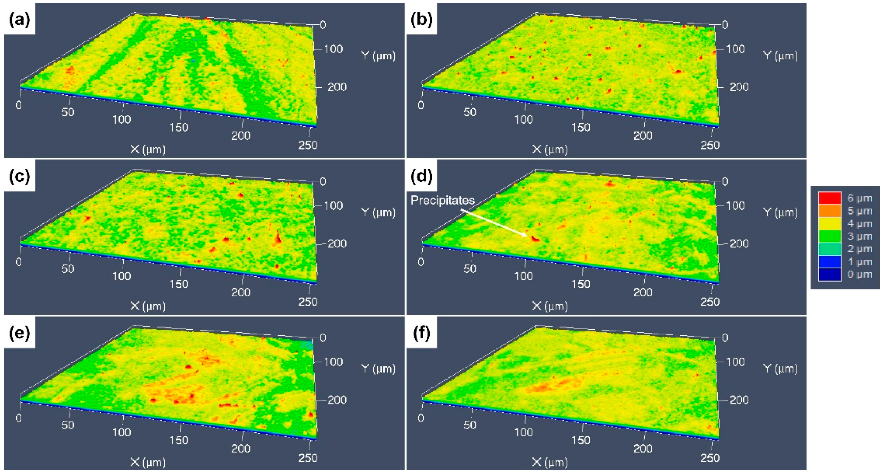
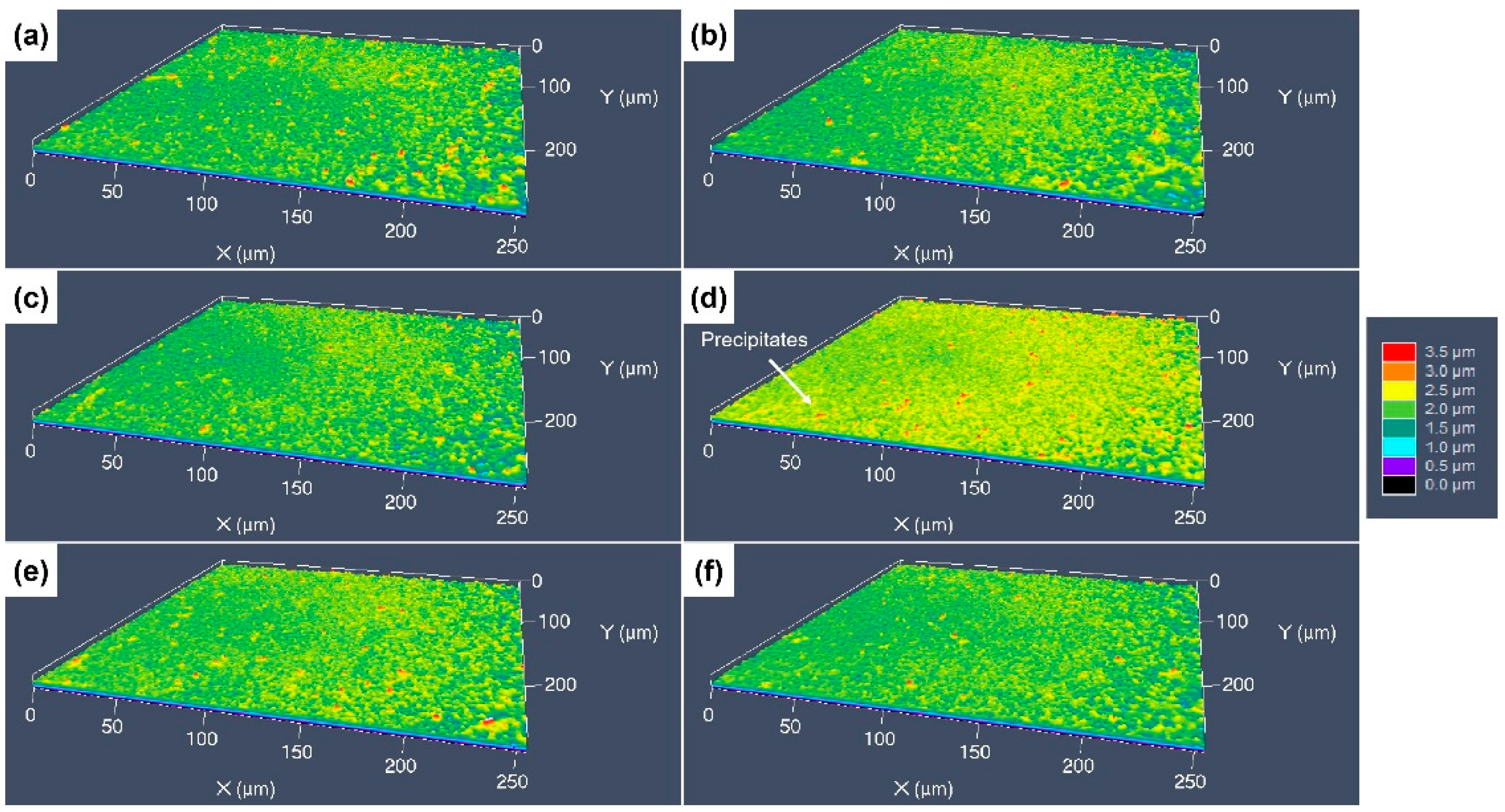
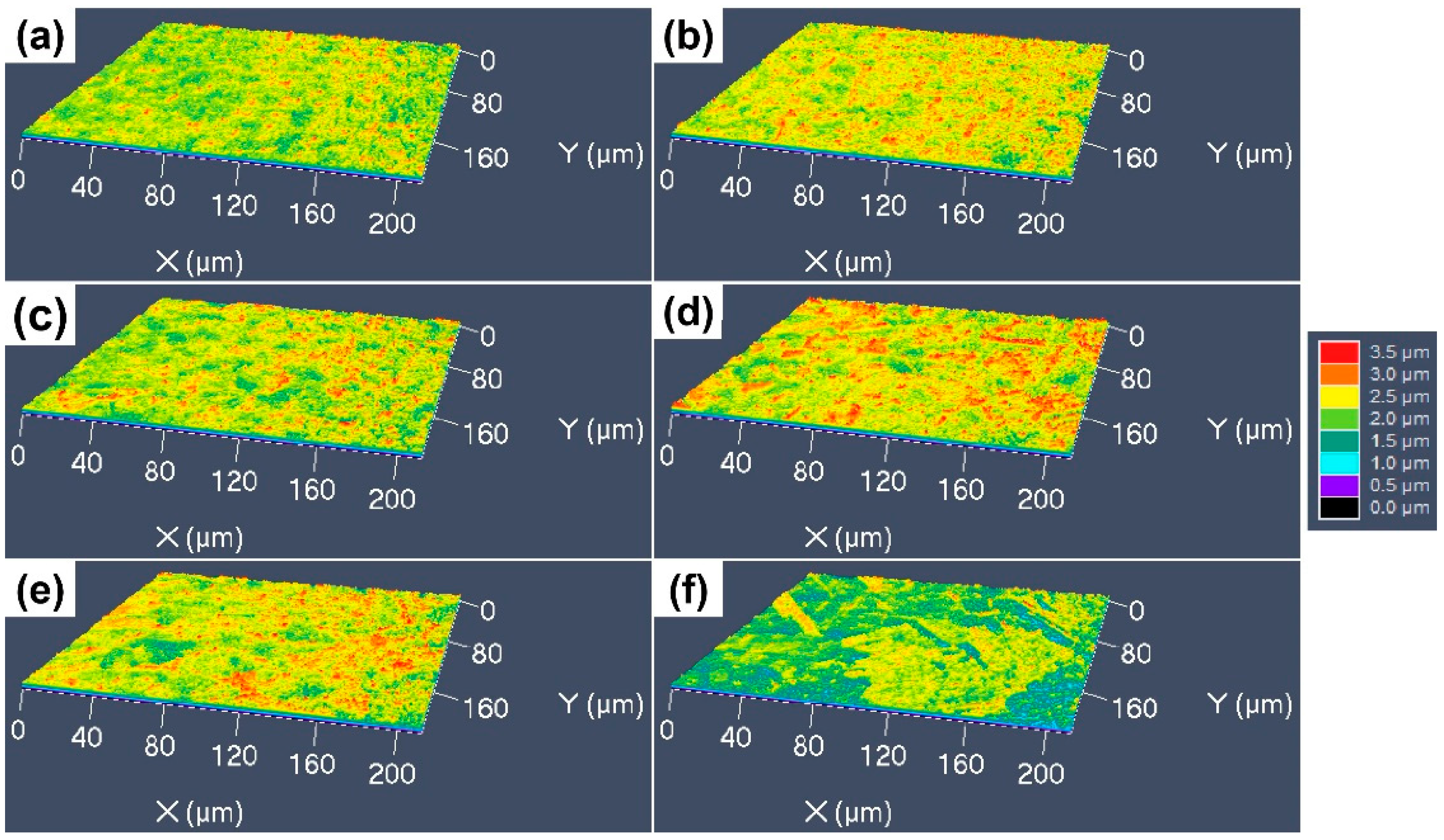
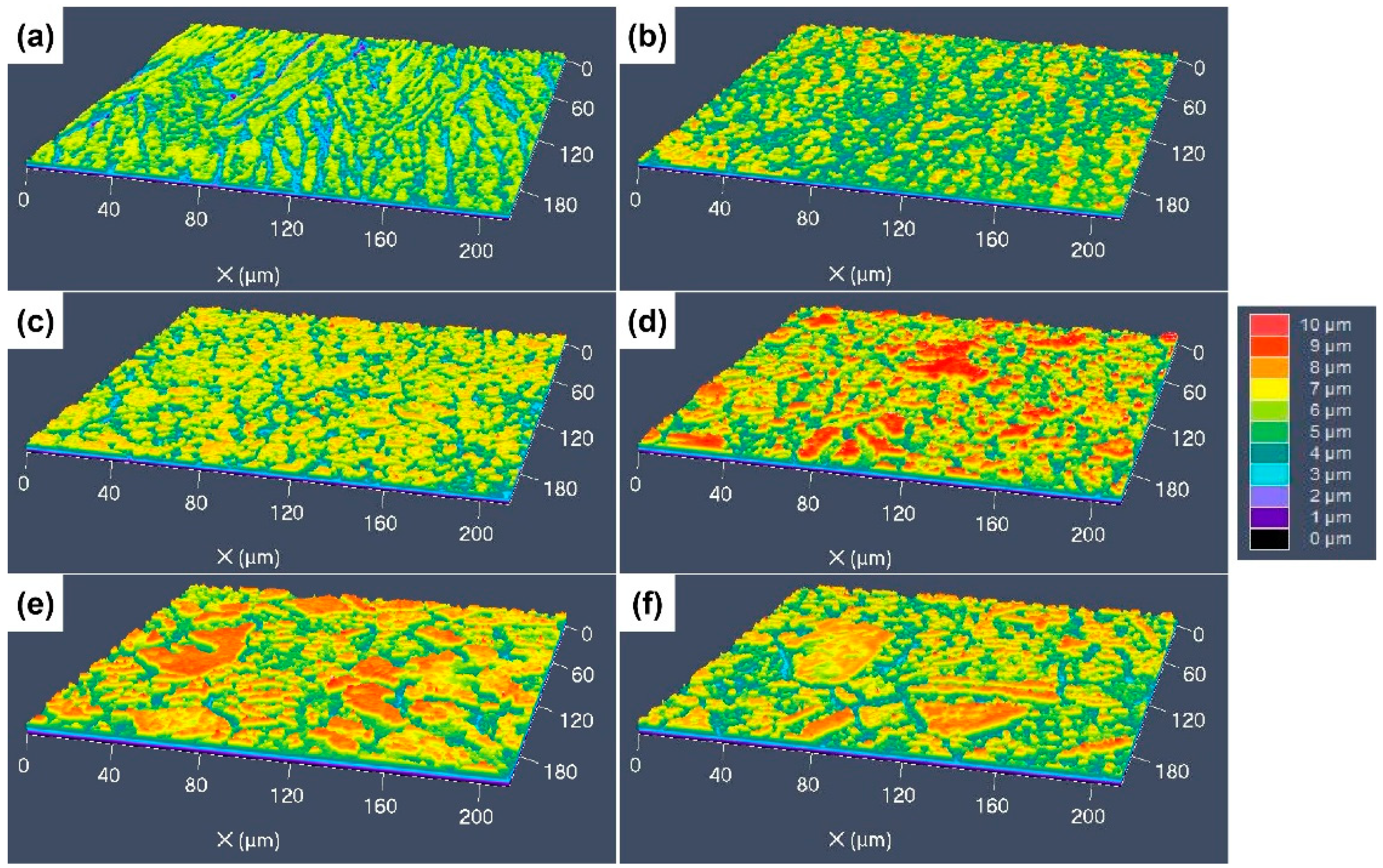
3.3. 3D Surface Undulations after Etching with Different Etchants

The 3D surface morphologies of the specimens etched by the four different etchants were characterized using CLSM to reveal the difference in height between the different areas of the etched surfaces, with different colors indicating the difference in height. Figure 8 shows the 3D morphologies of the specimens etched by aqua regia. For the cold-rolled specimens, the deep grooves around the GBs and dislocation groups can be clearly seen, and the difference in height between the grooves and the surrounding areas is about 3–4 μm. After an annealing at 600 °C, the deepest sites on the etched surface are located at the GBs, as presented in Figure 8b, and the difference in etch rates of different grains is not very obvious. As the annealing temperature increased, some protrusions with a red color appeared, as shown in Figure 8c–f. The obvious difference in the etching rate occurred not only at the GBs and inside the grains, but also between the different grains. Therefore, some red areas can be observed on the etched surfaces, and the height difference in the etched surfaces is about 5–6 μm.
Figure 9 shows the 3D surface morphologies of the specimens etched using the FeCl3 etchant. For the original cold-rolled specimen, it seems that the etch grooves at the dislocation groups become blurred, but still exist. The depth of the etching grooves is only 1 μm, which is much shallower than that on the surface etched by aqua regia, and the width reaches to about 20 μm. In Figure 9b,c, some red protrudent particles can be seen, which are the residual Cr-rich precipitations. The height of these particles raised more than 2 μm. With increasing grain size, the protrudent etch-resistant grains can be observed, as presented in Figure 9d–f, but the height of the protrusions is only 2–3 μm.
The 3D surface morphologies of the specimens etched by the CuCl2-1 etchant are shown Figure 10. It can be found that all the surfaces are very flat, with no obvious protrusions, as shown in Figure 10a–c; the dislocation groups, GBs and grain orientation have a little influence on the etching surface. For the specimens with coarser grains, some fine red particles can still be found on the etched surfaces (see Figure 10d–f), which is consistent with the SEM images. Figure 11 shows the 3D surface morphology of the specimens etched by the CuCl2-2 etchant, for which the surface fluctuation is larger than that etched by the CuCl2-1 etchant. For the cold-rolled specimens, the deformation defects had a little influence on the etched surface, but the grain orientation had an obvious influence and formed some protrudent grains.

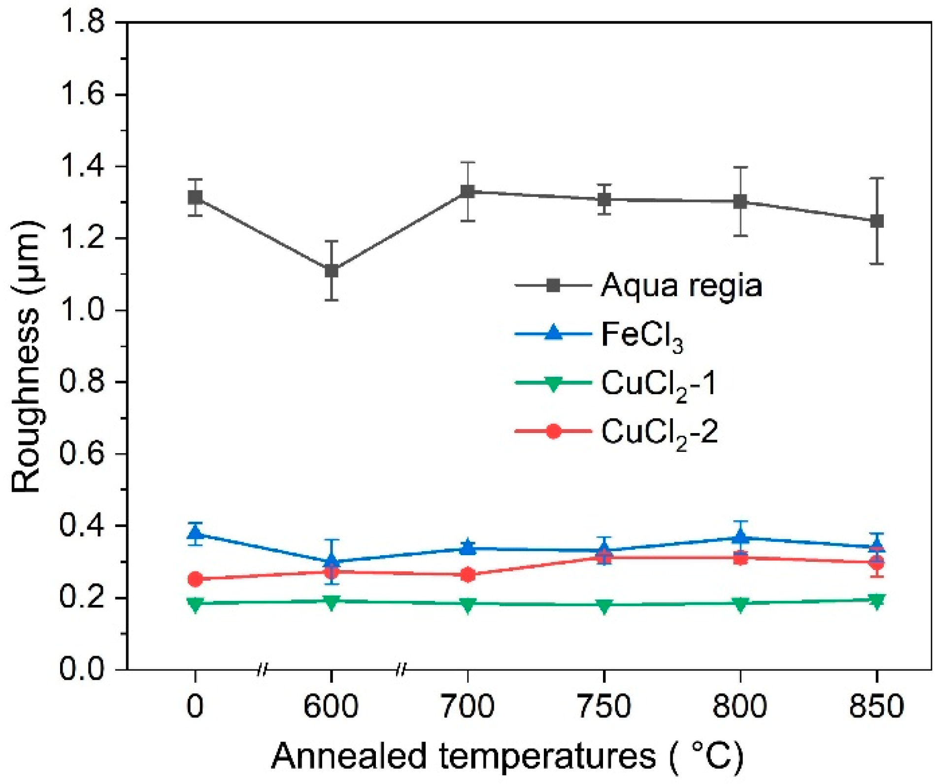
3.4. Surface Roughness

The obtained surface roughness of the specimens etched by different etchants is shown in Figure 12. For the surfaces etched with aqua regia, they are significantly rougher because preferential etching at the GBs and dislocation groups in aqua regia is very serious. However, it seems that the FeCl3 and CuCl2 etchants are insensitive to these defects; thus, the GBs and defects are blurred and almost indistinguishable on the etched surface. It was revealed that the grain size affects the roughness of the CuCrSn alloy surface etched by aqua regia [21]. For FeCl3 and the two CuCl2 etchants, recrystallization and grain growth has a little influence on the etched surface roughness, although the etched surface morphology is affected by the grain structure, and the annealing temperature–surface roughness curves show almost no fluctuations. Figure 13 shows the microscopic surface morphologies of the CuCrSn specimens etched by the four etchants, with the same magnification factor, in which the difference in surface roughness is very clear.

3.5. Discussion

From the above experimental results, it can be found that the grain structure, GBs and dislocation groups of the CuCrSn alloy can affect the etched surface morphology, whereas the influence levels of these factors are quite different in the different etchants. In aqua regia, the main substance that reacts with Cu is concentrated nitric acid, and Cl easily forms complexes with Cu2+, which decreases the reduction potential of Cu and accelerates the reaction. The reaction equation is as follows [26]:
C u s + 4 H N O 3 a q = 2 H 2 O ( l ) + 2 N O 2 ( g ) + C u N O 3 2 ( a q )
During the etching process, Cu is directly oxidized into Cu2+, and then rapidly dissolved. As the reactivity of the atoms near defects and the GBs is higher, which accelerates the dissolution rate, the aqua regia etchant is strongly influenced by the defects, GBs and crystal orientation. Moreover, the bonding energies between the different atomic planes are different, resulting in a difference in the etching rates of grains of different orientations and very fine step morphologies within the etched surface of the grains [21].
For the FeCl3 etchant, the Fe3+ ions on the surface of the alloy oxidize Cu atoms into Cu+, and the resulting CuCl is insoluble in the solution and will cover the surface of the alloy. Then, the CuCl can be further oxidized by Fe3+ into CuCl2; the reaction equation is as follows [16,27,28]:
C u ( s ) + F e C l 3 ( a q ) = C u C l ( s ) + F e C l 2 ( a q )
C u C l ( s ) + F e C l 3 ( a q ) = C u C l 2 ( a q ) + F e C l 2 ( a q )
For etching in the FeCl3 etchant, the Cu atoms at the surface are in direct contact with Fe3+ in the beginning; thus, the etching rate is the highest. Since the dissolution rate of the CuCl is lower than the generation rate, CuCl film is formed on the alloy surface, which prevents Fe3+ from making contact with the alloy surface and hindering Reaction (2). As a result, the generation rate of the CuCl film decreases until the generation and dissolution of CuCl, achieving dynamic equilibrium, and the etching rate begins to stabilize [29,30]. Since there is a CuCl film that affects the etching mechanism, the surface morphology etched with the FeCl3 etchant is obviously different from that etched with aqua regia. The effects of the defects, GBs and grain orientation on etching can still be observed, but are suppressed to a large extent.
The reaction processes of the CuCl2 etchant with the Cu alloys are as follows [11,12,13]:
C u C l 2 ( a q ) + C u ( s ) = C u 2 C l 2 ( s )
C u 2 C l 2 ( s ) + 4 C l = 2 C u C l 3 2
The Cu2+ ions first oxidize the Cu atoms into Cu+, which also forms CuCl films. Unlike the FeCl3 etchant, the CuCl film can only be dissolved through the adsorption of Cl to form a complex, and the dissolution rate of the CuCl film in the CuCl2 etchant is lower than that in the FeCl3 etchant.
Figure 14 shows the characterization sites and the corresponding compositions of a specimen etched by the CuCl2-1 etchant, with no ultrasonic cleaning after etching, which demonstrates that the etched surface before ultrasonic cleaning is almost covered by CuCl. Therefore, the influence of the CuCl film on the etching process is more serious, while the influence of the defects, GBs and grain orientation on the etching process is much weaker, so the consistency of the etched surface in the CuCl2 etchant is better, and the surface is less rough. The CuCl2-2 etchant has a higher content of Cl and Cu2+, making it more erosive to the CuCl film and the etching is less uniform. As the difference in etching rates of CuCl2 in the matrix and the precipitates is low, the residual precipitation particles on the surfaces etched by the CuCl2 etchant are smaller in size.

4. Conclusions

The etching surface of a set of the CuCrSn alloy specimens with different microstructures and grain sizes by four different etchants (aqua regia, FeCl3, CuCl2-1 and CuCl2-2) were characterized in this study. The main conclusions are as follows:
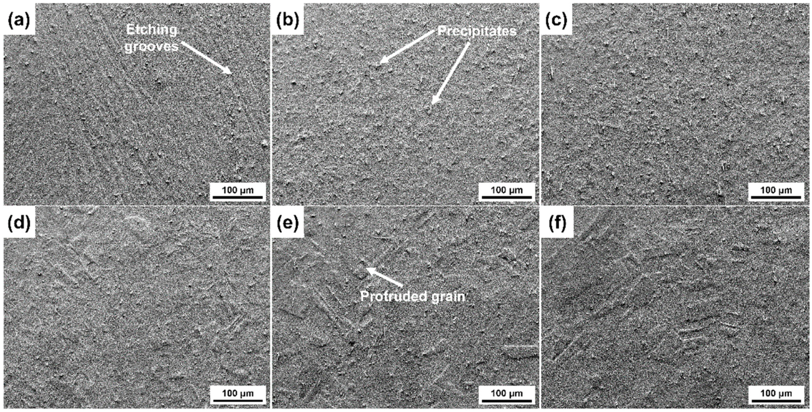
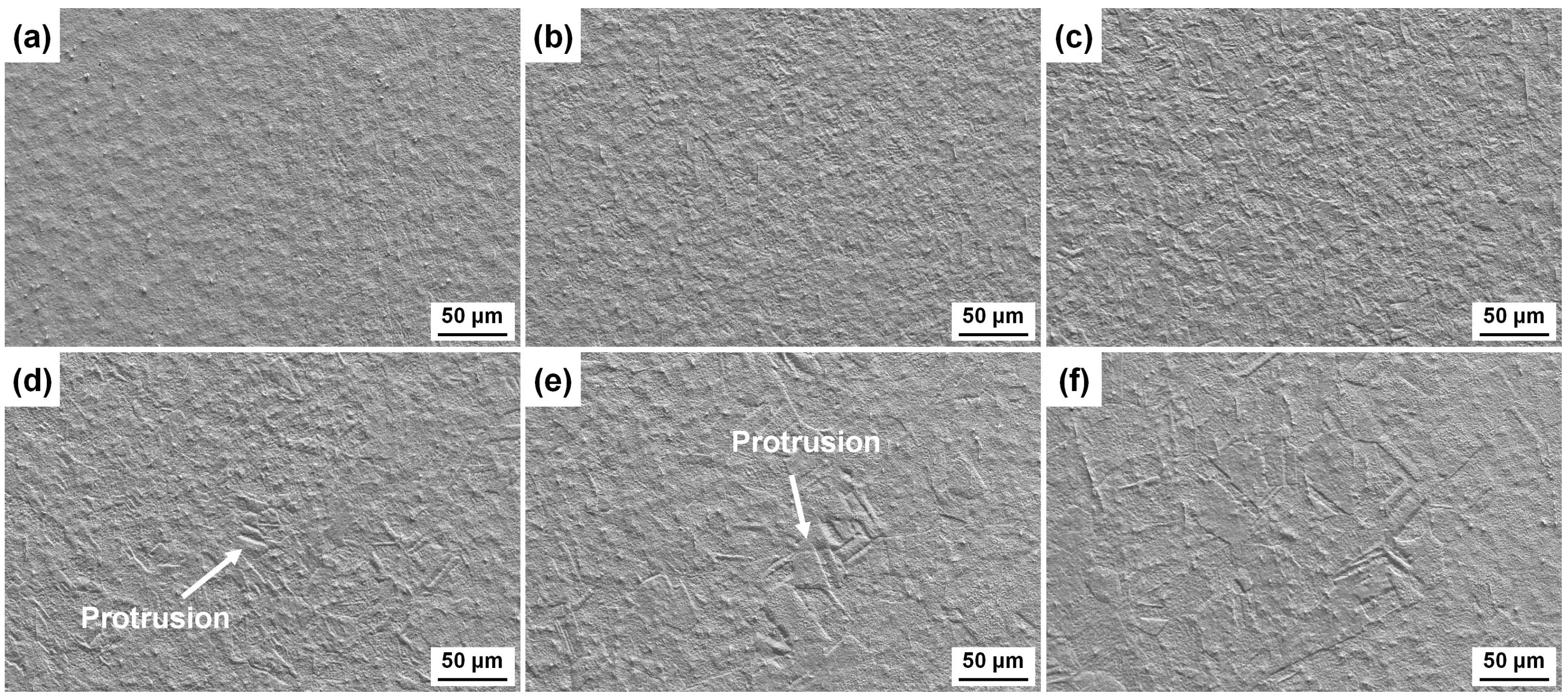
  • The etching rate in aqua regia is high, and the grain orientation, GBs and dislocations have significant influences on the etching rate, the height difference between the etch-resistant grains and the surrounding grains of about 5–6 μm. The preferential etching of some atomic planes forms steps at some GBs, and preferential etching around the GB and dislocation group forms grooves. For etching with the FeCl3 and CuCl2-2 etchants, such steps and grooves become blurred and almost invisible on the surface etched by the CuCl2-1 etchant.
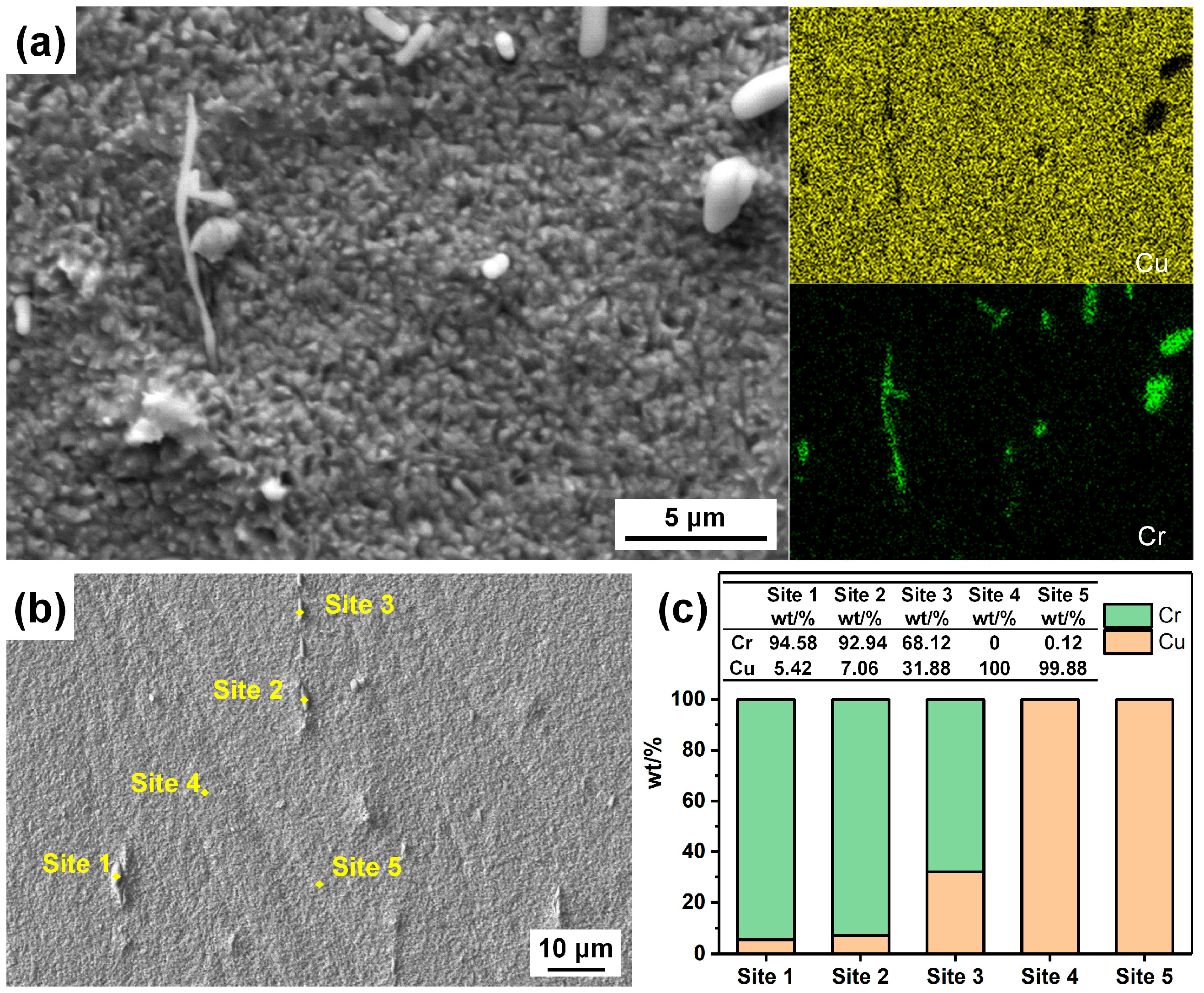
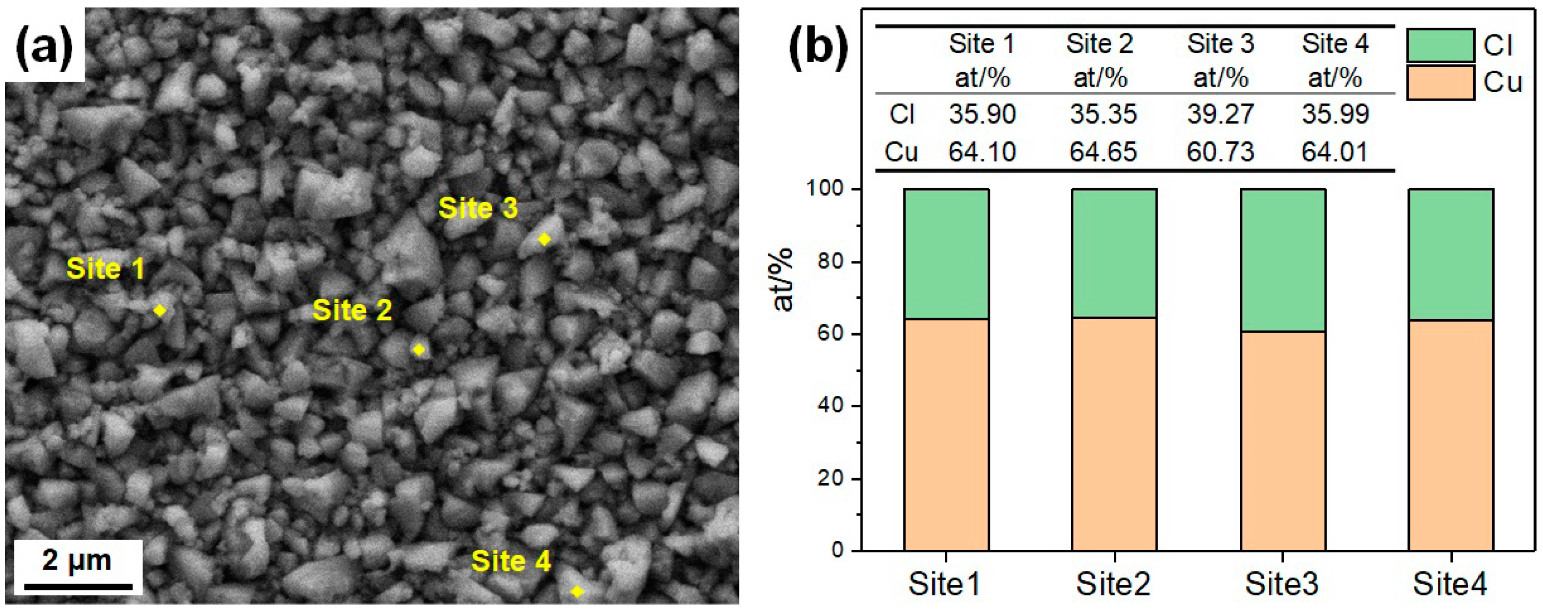
  • The CuCrSn alloy surface etched by aqua regia is clean, with very little Cr-rich particles. For the specimens etched with the FeCl3 and CuCl2 etchants, high-density Cr-rich particles remained on the surfaces; thus, etching in these two etchants is more likely to be affected by the alloy composition and the precipitations.
  • Due to the serious difference in etching rate at the different locations, the surface roughness of the specimens etched by aqua regia is about 1.27 μm. There is a little fluctuation on the surfaces etched with the FeCl3 and CuCl2 etchants; thus, the surface roughness are only around 0.2~0.3 μm. For the same kind of etchant, the ion concentration can affect the etched surface morphology, although not fundamentally.

Author Contributions

Conceptualization, Q.Z. and F.L.; methodology, Q.Z. and J.F.; investigation, J.F.; resources, X.Z. and C.L.; writing—original draft preparation, J.F.; writing—review and editing, Q.Z., C.X. and L.Y.; supervision, C.X. and Z.S.; funding acquisition, C.L. and Z.S. All authors have read and agreed to the published version of the manuscript.

Funding

This study was funded by the “Scientific and Technological Innovation 2025” Major Special Project of Ningbo City under grant No. 2021Z049.

Institutional Review Board Statement

Not applicable.

Informed Consent Statement

Not applicable.

Data Availability Statement

Data are contained within the article.

Acknowledgments

The authors acknowledge Y.P. Wei, R.R. Jiang and Y.Y. Yao for the microstructure observation.

Conflicts of Interest

Authors Xinli Zhang and Chaofeng Li were employed by the company Ningbo Kangqiang Electronics Co., Ltd. And Author Feng Liu was employed by the company Ningbo Xingye Shengtai Group Co., Ltd. The remaining authors declare that the research was conducted in the absence of any commercial or financial relationships that could be construed as a potential conflict of interest.

References

  1. Visser, A.; Buhlert, M. Theoretical and practical aspects of the miniaturization of lead frames by double sided asymmetrical spray etching. J. Mater. Process. Technol. 2001, 115, 108–113. [Google Scholar] [CrossRef]
  2. Zhao, W.C.; Feng, R.; Wang, X.W.; Wang, Y.X.; Pan, Y.K.; Gong, B.K.; Han, X.J.; Feng, T.J. Effect of grain boundaries and crystal orientation on etching behavior of 12 µm thick rolled copper foil. Mater. Today Commun. 2023, 34, 105029. [Google Scholar] [CrossRef]
  3. Kim, B.J.; Jeon, H.I.; Kim, G.J.; Cho, N.H.; Khim, J.Y.; Kim, Y.K. Wettable flank routable thin Micro Lead Frame for automotive applications. Microelectron. Reliab. 2022, 135, 114602. [Google Scholar] [CrossRef]
  4. Yang, H.Y.; Ma, Z.C.; Lei, C.H.; Meng, L.; Fang, Y.T.; Liu, J.B.; Wang, H.T. High strength and high conductivity Cu alloys: A review. Sci. China Technol. Sci. 2020, 63, 2505–2517. [Google Scholar] [CrossRef]
  5. Yang, K.; Wang, Y.H.; Guo, M.X.; Wang, H.; Mo, Y.D.; Dong, X.G.; Lou, H.F. Recent development of advanced precipitation-strengthened Cu alloys with high strength and conductivity: A review. Prog. Mater. Sci. 2023, 138, 101141. [Google Scholar] [CrossRef]
  6. Williams, K.R.; Gupta, K.; Wasilik, M. Etch rates for micromachining processing-Part II. J. Microelectromech. Syst. 2003, 12, 761–778. [Google Scholar] [CrossRef]
  7. Çakır, O. Review of etchants for copper and its alloys in wet etching processes. Key Eng. Mater. 2008, 364, 460–465. [Google Scholar]
  8. Zhang, Y.; Zhang, Z.T.; Yang, J.L.; Yue, Y.K.; Zhang, H.F. Fabrication of superhydrophobic surface on stainless steel by two-step chemical etching. Chem. Phys. Lett. 2022, 797, 139567. [Google Scholar] [CrossRef]
  9. Allen, D.M.; Almond, H.J.A. Characterization of aqueous ferric chloride etchants used in industrial photochemical machining. J. Mater. Process. Technol. 2004, 149, 238–245. [Google Scholar] [CrossRef]
  10. Çakır, O. Chemical etching of aluminum. J. Mater. Process. Technol. 2008, 199, 337–340. [Google Scholar] [CrossRef]
  11. Sheng, J.Z.; Li, H.; Shen, S.N.; Ming, R.J.; Sun, B.; Wang, J.; Zhang, D.D.; Tang, Y.G. Investigation on chemical etching process of FPCB with 18 μm line pitch. IEEE Access 2021, 9, 50872–50879. [Google Scholar] [CrossRef]
  12. Çakır, O.; Temel, H.; Kiyak, M. Chemical etching of Cu-ETP copper. J. Mater. Process. Technol. 2005, 162, 275–279. [Google Scholar] [CrossRef]
  13. Choi, J.C.; Lee, J.H. Etching behaviors of Cu and invar for metal core PCB applications. J. Nanosci. Nanotechnol. 2017, 17, 7358–7361. [Google Scholar] [CrossRef]
  14. Yang, Z.Y.; Huang, C.D.; Ji, X.Q.; Wang, Y.X. A new electrolytic method for on-site regeneration of acidic copper (II) chloride etchant in printed circuit board production. Int. J. Electrochem. Sci. 2013, 8, 6258–6268. [Google Scholar] [CrossRef]
  15. Darchen, A.; Drissi-Daoudi, R.; Irzho, A. Electrochemical investigations of copper etching by Cu (NH3) 4Cl2 in ammoniacal solutions. J. Appl. Electrochem. 1997, 27, 448–454. [Google Scholar] [CrossRef]
  16. Wang, S.F.; Ding, F.; Wang, F.W.; Wang, X.; Zou, H.L. Study on reducing side etching of Copper microelectrode by multi-step etching process. Mater. Res. Express 2019, 6, 126411. [Google Scholar] [CrossRef]
  17. Kondo, K.; Kurihara, H.; Murakami, H. Etching morphology of single-crystal copper. Electrochem. Solid State 2005, 9, C36. [Google Scholar] [CrossRef]
  18. Köllensperger, P.A.; Karl, W.J.; Ahmad, M.M.; Pike, W.T.; Green, M. Patterning of platinum (Pt) thin films by chemical wet etching in Aqua Regia. J. Micromech. Microeng. 2012, 22, 067001. [Google Scholar] [CrossRef]
  19. Seo, B.H.; Lee, S.H.; Park, I.S.; Seo, J.H.; Choe, H.H.; Jeon, J.H.; Hong, M.P. Effect of nitric acid on wet etching behavior of Cu/Mo for TFT application. Curr. Appl. Phys. 2011, 11, S262–S265. [Google Scholar] [CrossRef]
  20. Ralston, K.D.; Birbilis, N. Effect of grain size on corrosion: A review. Corrosion 2010, 66, 075005. [Google Scholar] [CrossRef]
  21. Fang, J.Y.; Li, C.F.; Liu, F.; Hou, H.L.; Zhang, X.L.; Zhang, Q.K.; Yang, L.J.; Xu, C.; Song, Z.L. Effects of grain orientation and grain size on etching behaviors of high-strength and high-conductivity Cu alloy. Mater. Today Commun. 2024, 38, 108111. [Google Scholar] [CrossRef]
  22. Peng, L.J.; Xie, H.F.; Huang, G.J.; Xu, G.L.; Yin, X.Q.; Feng, X.; Mi, X.J.; Yang, Z. The phase transformation and strengthening of a Cu-0.71 wt% Cr alloy. J. Alloys Compd. 2017, 708, 1096–1102. [Google Scholar] [CrossRef]
  23. Li, J.Z.; Ding, H.; Li, B.M.; Gao, W.L.; Bai, J.; Sha, G. Effect of Cr and Sn additions on microstructure, mechanical-electrical properties and softening resistance of Cu-Cr-Sn alloy. Mater. Sci. Eng. A 2021, 802, 140628. [Google Scholar] [CrossRef]
  24. Yamashita, M.; Mimaki, T.; Hashimoto, S.; Miura, S. Intergranular corrosion of copper and α-Cu-Al alloy bicrystals. Philos. Mag. A 1991, 63, 695–705. [Google Scholar] [CrossRef]
  25. Miyamoto, H.; Yoshimura, K.; Mimaki, T.; Yamashita, M. Behavior of intergranular corrosion of <011> tilt grain boundaries of pure copper bicrystals. Corros. Sci. 2002, 44, 1835–1846. [Google Scholar]
  26. Carlson, R.K.; Yang, P.; Clegg, S.M.; Batista, E.R. Mechanistic Study of the Production of NOx Gases from the Reaction of Copper with Nitric Acid. Inorg. Chem. 2020, 59, 16833–16842. [Google Scholar] [CrossRef]
  27. Atta, R.M. Effect of applying air pressure during wet etching of micro copper PCB tracks with ferric chloride. Int. J. Mater. Res. 2022, 113, 795–808. [Google Scholar] [CrossRef]
  28. Choi, J.C.; Lee, Y.S.; Lee, J.; Kwon, H.W.; Lee, J.H. Etching behaviors of galvanic coupled metals in PCB applications. In Proceedings of the 2018 Pan Pacific Microelectronics Symposium (Pan Pacific), Big Island, HI, USA, 5–8 February 2018; IEEE: Piscataway, NJ, USA, 2018; pp. 1–4. [Google Scholar]
  29. Jian, C.; Jusheng, M.; Gangqiang, W.; Xiangyun, T. Effects on etching rates of copper in ferric chloride solutions. In Proceedings of the 2nd 1998 IEMT/IMC Symposium (IEEE Cat. No. 98EX225), Tokyo, Japan, 15–17 August 2002; IEEE: Piscataway, NJ, USA, 2002; pp. 144–148. [Google Scholar]
  30. Braun, M.; Nobe, K. Electrodissolution kinetics of copper in acidic chloride solutions. J. Electrochem. Soc. 1979, 126, 1666. [Google Scholar] [CrossRef]
Figure 1. Microstructure of the different CuCrSn specimens: (a) the 80% cold-rolled specimen without annealing and the specimens further annealed at (b) 600 °C, (c) 700 °C, (d) 750 °C, (e) 800 °C or (f) 850 °C for 15 min after cold rolling.
Materials 17 01966 g001
Figure 2. Surface morphologies of the different CuCrSn specimens etched by aqua regia: (a) the 80% cold-rolled specimen without annealing and the specimens further annealed at (b) 600 °C, (c) 700 °C, (d) 750 °C, (e) 800 °C or (f) 850 °C for 15 min after cold rolling.
Materials 17 01966 g002
Figure 3. Surface morphologies of the different CuCrSn specimens etched by acidic FeCl3 etchant: (a) the 80% cold-rolled specimen without annealing and the specimens further annealed at (b) 600 °C, (c) 700 °C, (d) 750 °C, (e) 800 °C or (f) 850 °C for 15 min after cold rolling.
Materials 17 01966 g003
Figure 4. (a) Microscopic surface morphology and elemental distribution of the 80% cold-rolled specimen after being etched by the FeCl3 etchant, (b) sites for the EDS characterization and (c) compositions of these sites.
Materials 17 01966 g004
Figure 5. Surface morphologies of the different CuCrSn specimens etched by the CuCl2-1 acidic etchant: (a) the 80% cold-rolled specimen without annealing and the specimens further annealed at (b) 600 °C, (c) 700 °C, (d) 750 °C, (e) 800 °C or (f) 850 °C for 15 min after cold rolling.
Materials 17 01966 g005
Figure 6. Surface morphologies of the different CuCrSn specimens etched by the CuCl2-2 acidic etchant: (a) the 80% cold-rolled specimen without annealing and the specimens further annealed at (b) 600 °C, (c) 700 °C, (d) 750 °C, (e) 800 °C or (f) 850 °C for 15 min after cold rolling.
Materials 17 01966 g006
Figure 7. Surface morphologies and elemental distributions of the 80% cold-rolled specimen etched by the (a) CuCl2-1 and (b) CuCl2-2 etchants.
Materials 17 01966 g007
Figure 8. Three-dimensional morphologies of the different CuCrSn specimens etched by aqua regia: (a) the 80% cold-rolled specimen without annealing and the specimens further annealed at (b) 600 °C, (c) 700 °C, (d) 750 °C, (e) 800 °C or (f) 850 °C for 15 min after cold rolling.
Materials 17 01966 g008
Figure 9. Three-dimensional morphologies of the different CuCrSn specimens etched by the FeCl3 etchant: (a) the 80% cold-rolled specimen without annealing and the specimens further annealed at (b) 600 °C, (c) 700 °C, (d) 750 °C, (e) 800 °C or (f) 850 °C for 15 min after cold rolling.
Materials 17 01966 g009
Figure 10. Three-dimensional morphologies of the different CuCrSn specimens etched by the CuCl2-1 etchant: (a) the 80% cold-rolled specimen without annealing and the specimens further annealed at (b) 600 °C, (c) 700 °C, (d) 750 °C, (e) 800 °C or (f) 850 °C for 15 min after cold rolling.
Materials 17 01966 g010
Figure 11. Three-dimensional morphologies of the different CuCrSn specimens etched by the CuCl2-2 etchant: (a) the 80% cold-rolled specimen without annealing and the specimens further annealed at (b) 600 °C, (c) 700 °C, (d) 750 °C, (e) 800 °C or (f) 850 °C for 15 min after cold rolling.
Materials 17 01966 g011
Figure 12. Surface roughness of the CuCrSn alloy specimens etched by the 4 different etchants.
Materials 17 01966 g012
Figure 13. Microscopic surface morphologies of the specimens etched by the (a) aqua regia, (b) FeCl3, (c) CuCl2-1 and (d) CuCl2-2 etchants.
Materials 17 01966 g013
Figure 14. (a) Characterization sites and (b) the corresponding compositions of a specimen etched by the CuCl2-1 etchant, with no ultrasonic cleaning after etching.
Materials 17 01966 g014
Table 1. The preparation of specimens, etching and characterization methods in this study.
Alloy CompositionTreatments of SpecimensThe Four EtchantsCharacterization
Cu-0.437Cr-0.253 (wt%)
  • 80% cold-rolled;
  • annealed at 600 °C, 700 °C, 750 °C, 800 °C and 850 °C for 15 min after 80% cold-rolling
Aqua regia
  • metallographic microscope
  • SEM
  • CLSM
  • EDS
Acidic FeCl3 etchant: 45 g FeCl3·6H2O + 100 mL H2O + 10 mL concentrated HCl
CuCl2-1: 20 g CuCl2·2H2O + 100 mL H2O + 15 mL concentrated HCl
CuCl2-2: 28.5 g CuCl2·2H2O + 112 mL H2O + 10 mL concentrated HCl
Disclaimer/Publisher’s Note: The statements, opinions and data contained in all publications are solely those of the individual author(s) and contributor(s) and not of MDPI and/or the editor(s). MDPI and/or the editor(s) disclaim responsibility for any injury to people or property resulting from any ideas, methods, instructions or products referred to in the content.

