Electrical and Mechanical Performance of Carbon Fiber-Reinforced Polymer Used as the Impressed Current Anode Material

Abstract
:1. Introduction
2. Behavior of CFRP Plate in Simulated ICCP Systems
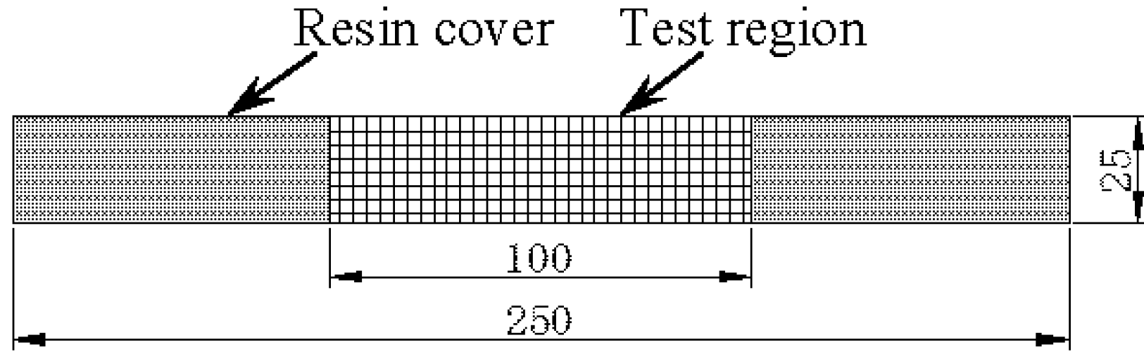
2.1. Specimen Preparation

| Series | Current (mA) | Test duration (day) | No. of specimens |
|---|---|---|---|
| G1-RF | – | 16 | 5 |
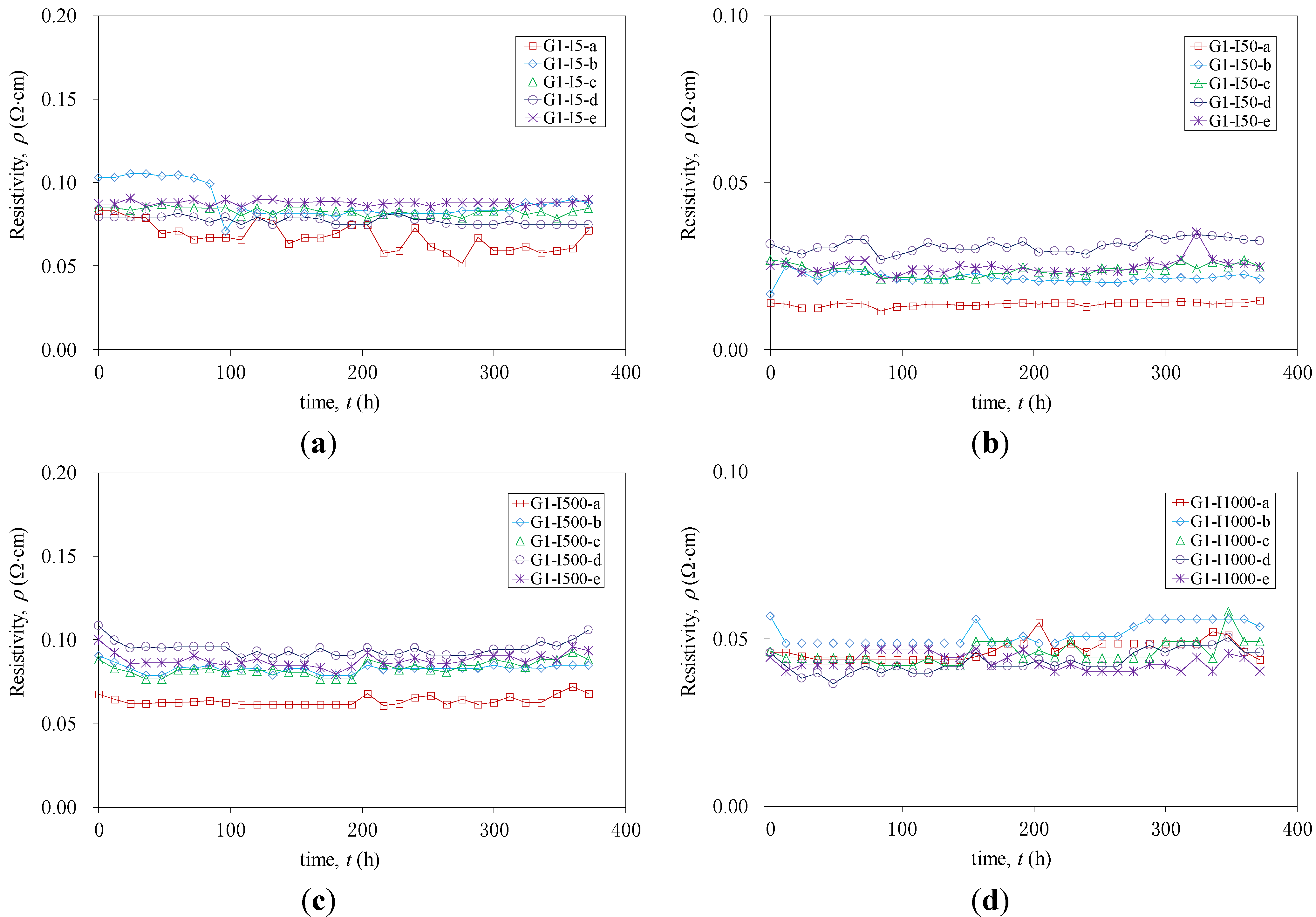
| G1-I5 | 5 | 16 | 5 |
| G1-I50 | 50 | 16 | 5 |
| G1-I500 | 500 | 16 | 5 |
| G1-I1000 | 1000 | 16 | 5 |
| Series | Specimen | Current (mA) | Current Density (A/m2) | Solution |
|---|---|---|---|---|
| G2-RF | G2-RF-NaCl | – | – | NaCl |
| G2-RF-Mix | – | – | Mix | |
| G2-RF-Ca(OH)2 | – | – | Ca(OH)2 | |
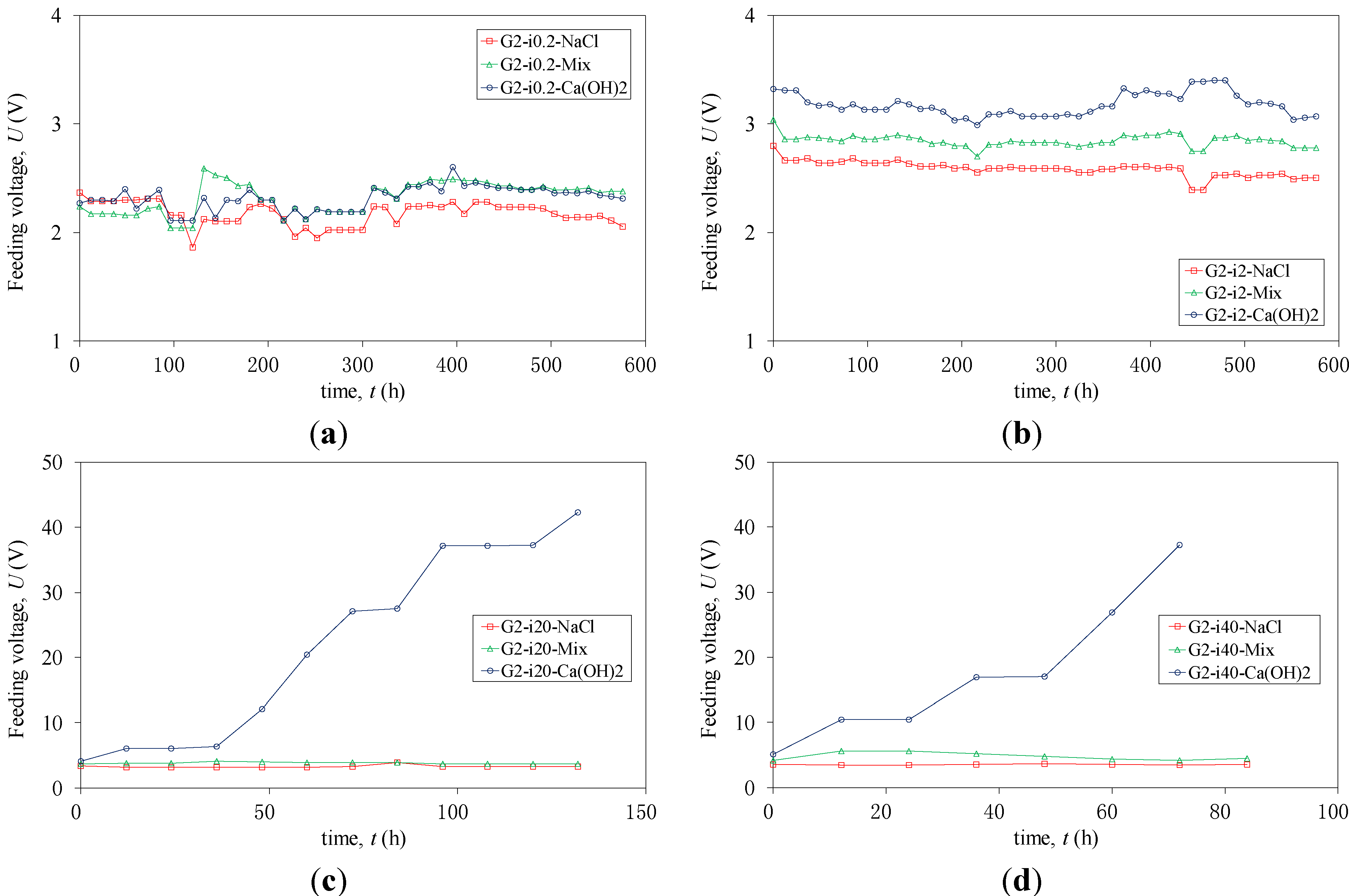
| G2-i0.2 | G2-i0.2-NaCl | 0.5 | 0.2 | NaCl |
| G2-i0.2-Mix | 0.5 | 0.2 | Mix | |
| G2-i0.2-Ca(OH)2 | 0.5 | 0.2 | Ca(OH)2 | |
| G2-i2 | G2-i2-NaCl | 5 | 2.0 | NaCl |
| G2-i2-Mix | 5 | 2.0 | Mix | |
| G2-i2-Ca(OH)2 | 5 | 2.0 | Ca(OH)2 | |
| G2-i20 | G2-i20-NaCl | 50 | 20.0 | NaCl |
| G2-i20-Mix | 50 | 20.0 | Mix | |
| G2-i20-Ca(OH)2 | 50 | 20.0 | Ca(OH)2 | |
| G2-i40 | G2-i40-NaCl | 100 | 40.0 | NaCl |
| G2-i40-Mix | 100 | 40.0 | Mix | |
| G2-i40-Ca(OH)2 | 100 | 40.0 | Ca(OH)2 |

| Ingredient Name | Concentration (%) | Ingredient Name | Concentration (%) |
|---|---|---|---|
| Polyoxypropylenediamine | 30–50 | Aminoethylpiperazine | 0–10 |
| Formaldehyde, polymer with benzenamine, hydrogenated | 10–20 | 1,3-Propandiamine, N,N'-1,2-ethandiylbis- | 0–10 |
| Cyclohexanediamine, 1,2- | 10–20 | Benzene-1,3-dimethanamine | 0–10 |
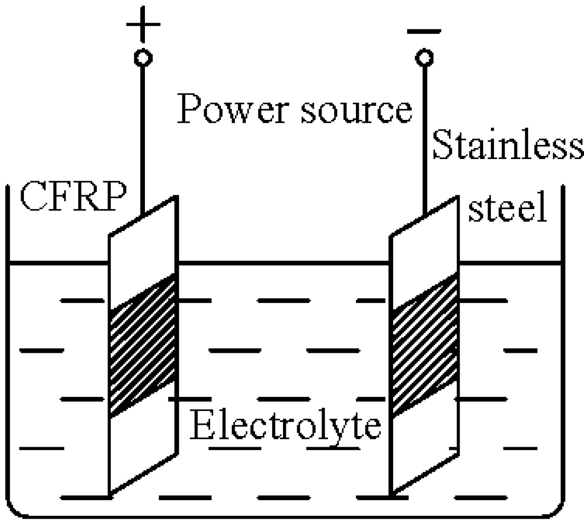
2.2. Impressed Current Tests

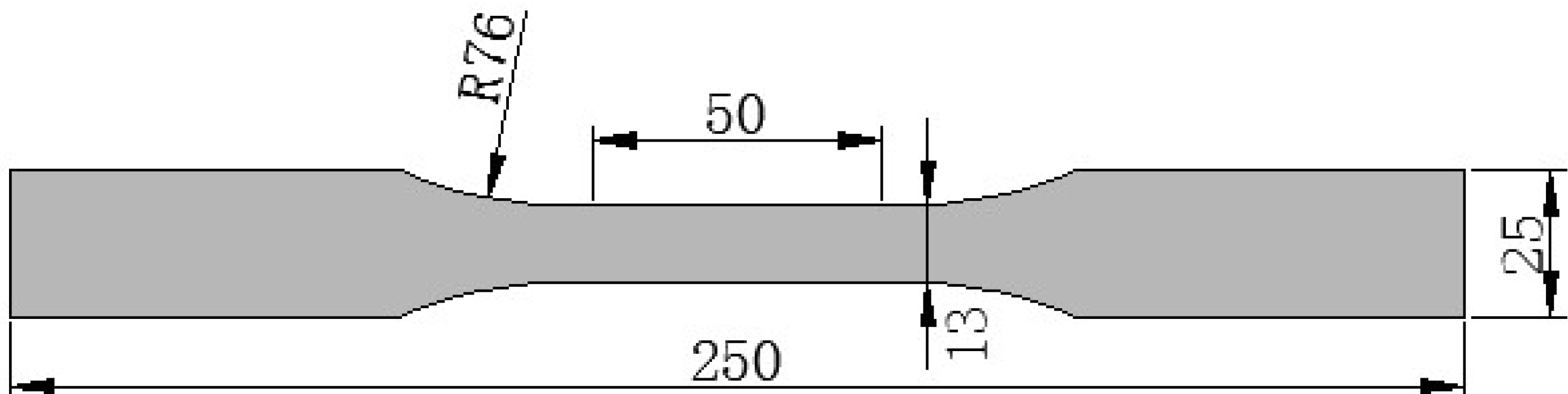
2.3. Tensile Test

3. Test Results
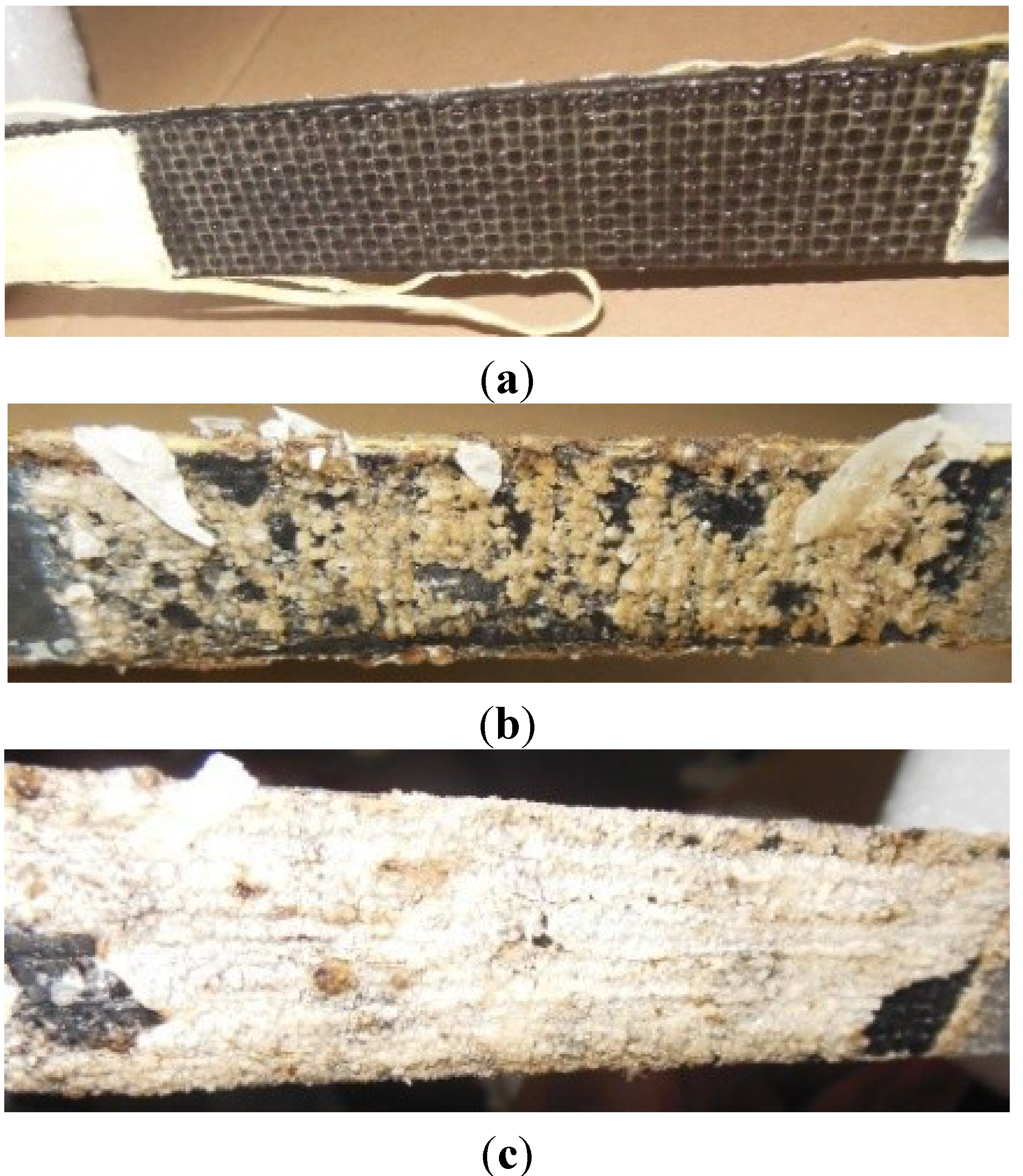
3.1. Experimental Observations

3.2. Electrical Performance


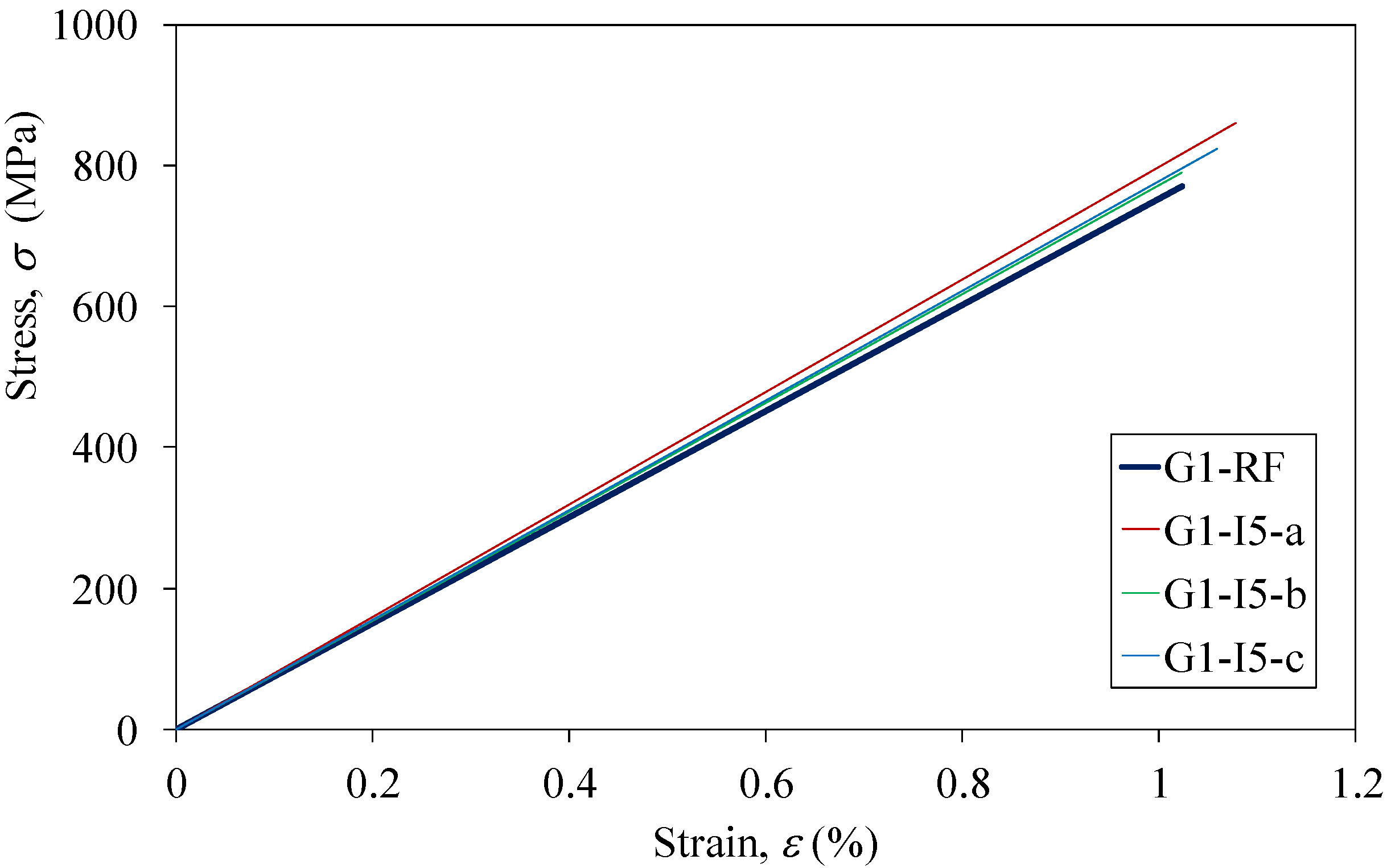
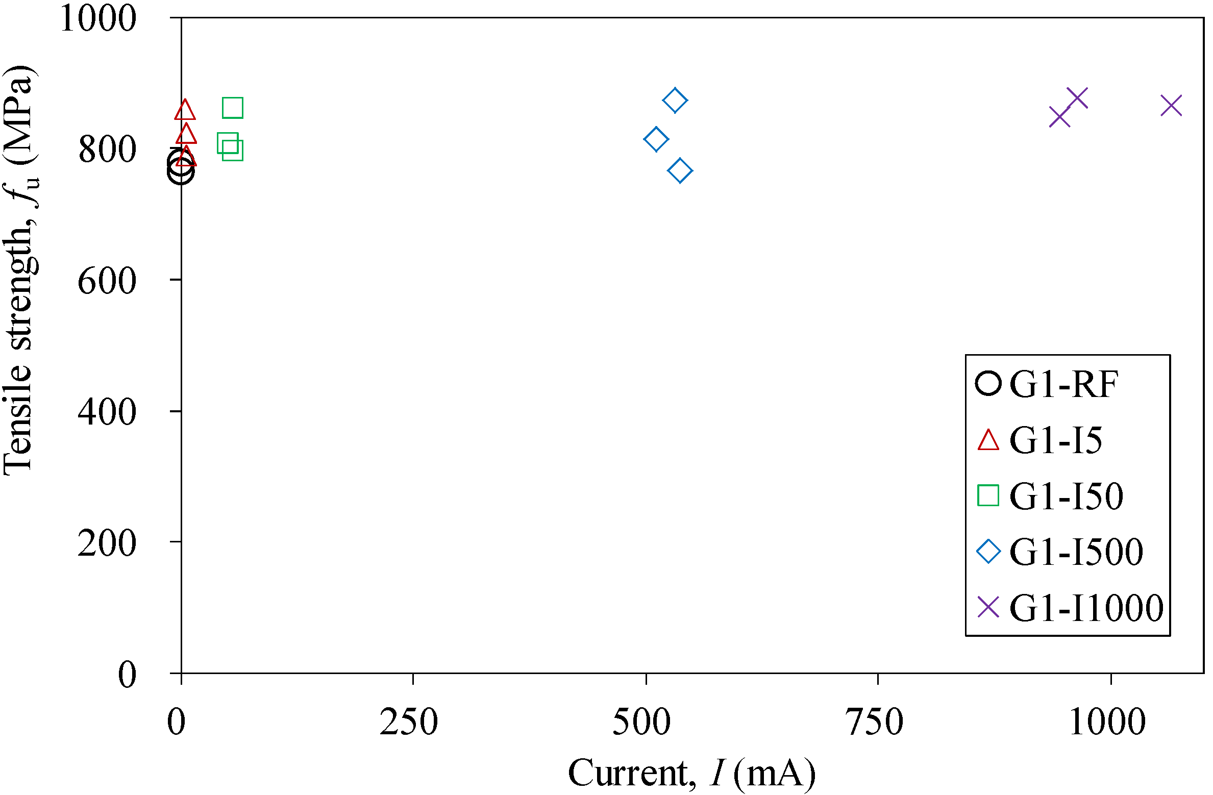
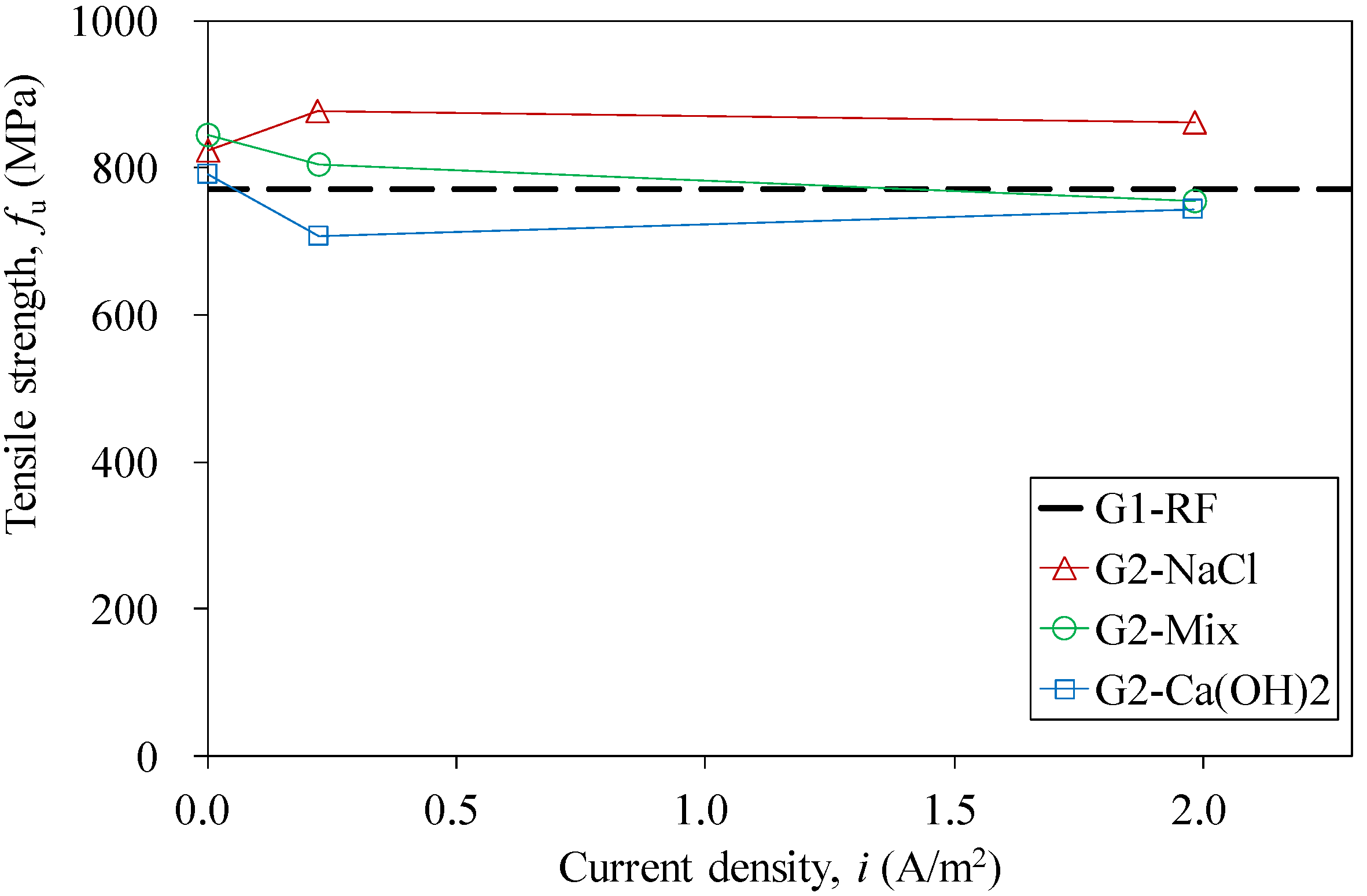
3.3. Mechanical Properties


| Series | Test Results | Comparison | ||
|---|---|---|---|---|
| fu (MPa) | E0 (GPa) | fu/fu,RF | E0/E0,RF | |
| G1-RF | 770.4 | 75.29 | – | – |
| G1-I5 | 824.6 | 78.27 | 1.07 | 1.04 |
| G1-I50 | 822.2 | 79.26 | 1.07 | 1.05 |
| G1-I500 | 818.1 | 75.39 | 1.06 | 1.00 |
| G1-I1000 | 863.8 | 75.78 | 1.12 | 1.01 |

| Specimen | Test Results | Comparison | ||
|---|---|---|---|---|
| fu (MPa) | E0 (GPa) | fu/fu,RF-NaCl | E0/E0,RF-NaCl | |
| G2-RF-NaCl | 824.0 | 76.24 | – | – |
| G2-i0.2-NaCl | 877.0 | 73.93 | 1.06 | 0.97 |
| G2-i2-NaCl | 861.2 | 73.78 | 1.05 | 0.97 |
| Specimen | Test Results | Comparison | ||
|---|---|---|---|---|
| fu (MPa) | E0 (GPa) | fu/fu,RF-Mix | E0/E0,RF-Mix | |
| G2-RF-Mix | 843.8 | 77.42 | – | – |
| G2-i0.2-Mix | 804.9 | 73.18 | 0.95 | 0.95 |
| G2-i2-Mix | 754.3 | 74.66 | 0.89 | 0.96 |
| Specimen | Test Results | Comparison | ||
|---|---|---|---|---|
| fu (MPa) | E0 (GPa) | fu/fu,RF-Ca(OH)2 | E0/E0,RF-Ca(OH)2 | |
| G2-RF-Ca(OH)2 | 790.3 | 73.46 | – | – |
| G2-i0.2-Ca(OH)2 | 707.1 | 68.38 | 0.89 | 0.93 |
| G2-i2-Ca(OH)2 | 743.4 | 66.38 | 0.94 | 0.90 |
4. Discussion of Service Life


5. Conclusions
- (1)
- Stable electrical and mechanical behaviors were observed in the experiments operated with only direct current.
- (2)
- Tests were also carried out in simulated ICCP systems with various solutions. No significant degradation in both electrical and mechanical performances was found for CFRP strips operated with current densities of 0.2 and 2 A/m2.
- (3)
- It is demonstrated that the CFRP plate can serve as the anode material in the ICCP system. The minimum predicted service life is 12 years, even with the maximum acceptable protection current density and reinforcement ratio. It should be noted that the prediction is conservative.
Notation
| Aa | Anodic surface area of CFRP |
| Ac | Cross-sectional area of the concrete element |
| Asteel | Surface area of each steel rebar in the concrete element |
| E | Steel potential measured against CSE |
| E0 | Elastic modulus for CFRP strips |
| E0,RF, E0,RF-NaCl, E0,RF-Mix, E0,RF-Ca(OH)2 | Elastic modulus for G1RF, G2RF-NaCl, G2RF-Mix, G2RF-Ca(OH)2, respectively |
| fu | Ultimate tensile strength of CFRP strips |
| fu,RF, fu,RF-NaCl, fu,RF-Mix, fu,RF-Ca(OH)2 | Ultimate tensile strength for G1RF, G2RF-NaCl, G2RF-Mix, G2RF-Ca(OH)2, respectively |
| I | Current |
| i | Current density |
| ip | Protection current density |
| n | Number of steel rebars in the concrete element |
| Qanode | Anode’s capacity to transfer charge |
| Qcathode | Total charge quantity passed the cathode during cathodic protection |
| QCFRP | CFRP plate’s capacity to transfer charge |
| Qsteel | Total charge quantity passed the steel in the concrete element during cathodic protection |
| R | Resistance |
| t | Time |
| tg | Duration of impressed current |
| tlife | Predicted service life of the ICCP system by QCFRP |
| U | Voltage |
| ρ | Reinforcement ratio |
| σ | Tensile stress |
| ε | Tensile strain |
Acknowledgments
Author Contributions
Conflicts of Interest
References
- ACI Committee 222R-01. In Protection of Metals in Concrete Against Corrosion; American Concrete Institute: Farmington Hills, MI, USA, 2001; pp. 16–18.
- Zhao, Y.X.; Karimi, A.R.; Wong, H.S.; Hu, B.Y.; Buenfeld, N.R.; Jin, W.L. Comparison of uniform and non-uniform corrosion induced damage in reinforced concrete based on a Gaussian description of the corrosion layer. Corros. Sci. 2011, 53, 2803–2814. [Google Scholar] [CrossRef]
- Zhao, Y.X.; Hu, B.Y.; Yu, J.; Jin, W.L. Non-uniform distribution of rust layer around steel bar in concrete. Corros. Sci. 2011, 53, 4300–4308. [Google Scholar] [CrossRef]
- Tang, L. Concentration dependence of diffusion and migration of chloride ions: Part 1. Theoretical considerations. Cem. Concr. Res. 1999, 29, 1463–1468. [Google Scholar] [CrossRef]
- Tang, L.P. Concentration dependence of diffusion and migration of chloride ions: Part 2. Experimental evaluations. Cem. Concr. Res. 1999, 29, 1469–1474. [Google Scholar] [CrossRef]
- Li, L.Y.; Page, C.L. Finite element modelling of chloride removal from concrete by an electrochemical method. Corros. Sci. 2000, 42, 2145–2165. [Google Scholar] [CrossRef]
- Cigna, R.; Andrade, C.; Nürnberger, U.; Polder, R.; Weydert, R.; Seitz, E. Corrosion of Steel in Reinforced Concrete Structures; European Cooperation in the Field of Scientific and Technical Research Report, COST Action 521; European Communities: Brussels, Belgium, 2003. [Google Scholar]
- Chung, D.D.L. Corrosion control of steel-reinforced concrete. J. Mater. Eng. Perform. 2000, 9, 585–588. [Google Scholar] [CrossRef]
- Bertolini, L.; Bolzoni, F.; Pedeferri, P.; Lazzari, L.; Pastore, T. Cathodic protection and cathodic prevention in concrete: Principles and applications. J. Appl. Electrochem. 1998, 28, 1321–1331. [Google Scholar] [CrossRef]
- Pedeferri, P. Cathodic protection and cathodic prevention. Constr. Build. Mater. 1996, 10, 391–402. [Google Scholar] [CrossRef]
- Barnhart, R. FHWA Position on Cathodic Protection Systems; Memorandum of FHWA; FHWA: Washington, DC, SA, 1982. [Google Scholar]
- Bullard, S.J.; Covino, B.S., Jr.; Cramer, S.D.; McGill, G.E. Thermal-Sprayed Zinc Anodes for Cathodic Protection of Steel-Reinforced Concrete Bridges; Albany Research Center (ARC): Albany, OR, USA; Oregon Department of Transportation: Salem, OR, USA, 1996. [Google Scholar]
- Brousseau, R.; Arsenault, B.; Dallaire, S.; Rogers, D.; Mumby, T.; Dong, D. Sprayed titanium coatings for the cathodic protection of reinforced concrete. J. Therm. Spray Technol. 1998, 7, 193–196. [Google Scholar] [CrossRef]
- Cramer, S.D.; Covino, B.S.; Holcomb, G.R.; Bullard, S.J.; Collins, W.K.; Govier, R.D.; Wilson, R.D.; Laylor, H.M. Thermal sprayed titanium anode for cathodic protection of reinforced concrete bridges. J. Therm. Spray Technol. 1999, 8, 133–145. [Google Scholar] [CrossRef]
- Clemena, G.G.; Jackson, D.R. Cathodic Protection of Concrete Bridge Decks Using Titanium-Mesh Anodes; Virginia Transportation Research Council Research Report, VTRC 00-R14; Virginia Transportation Research Council: Charlottesville, VA, USA, 2000. [Google Scholar]
- Clemena, G.G.; Jackson, D.R. Long-term performance of a Conductive-Paint Anode in Cathodic Protection Systems for Inland Concrete Bridge Piers in Virginia. Transp. Res. Rec. J. Transp. Res. Board 1998, 1642, 43–50. [Google Scholar] [CrossRef]
- Orlikowski, J.; Cebulski, S.; Darowicki, K. Electrochemical investigations of conductive coatings applied as anodes in cathodic protection of reinforced concrete. Cem. Concr. Comp. 2004, 26, 721–728. [Google Scholar] [CrossRef]
- BS EN 1504-4. In Products and Systems for the Protection and Repair of Concrete Structures—Definitions, Requirements, Quality Control and Evaluation of Conformity—Part 4: Structural Bonding; British Standards Institute: London, UK, 2004.
- ACI Committee 562M-13. In Code Requirements for Evaluation, Repair and Rehabilitation of ConcreteBuildings and Commentary; American Concrete Institute: Farmington Hills, MI, USA, 2013.
- Raupach, M.; Elsener, B. Corrosion of Reinforcement in Concrete: Mechanisms, Monitoring, Inhibitors and Rehabilitation Techniques; Woodhead Publishing Limited: Cambridge, UK, 2007. [Google Scholar]
- Lee-Orantes, F.; Torres-Acosta, A.A.; Martinez-Madrid, M.; Lopez-Cajun, C. Cathodic protection in reinforced concrete elements, using carbon fibers based composites. In Proceedings of the Corrosion of Infrastructure—210th ECS Meeting, Cancun, Mexico, 29 October–3 November 2006.
- Gadve, S.; Mukherjee, A.; Malhotra, S.N. Corrosion Protection of Fiber-Reinforced Polymer-Wrapped Reinforced Concrete. ACI Mater. J. 2010, 107, 349–356. [Google Scholar]
- Gadve, S.; Mukherjee, A.; Malhotra, S.N. Active Protection of Fiber-Reinforced Polymer-Wrapped Reinforced Concrete Structures against Corrosion. Corrosion 2011, 67, 025002:1–025002:11. [Google Scholar]
- Nguyen, C.V.; Lambert, P.; Mangat, P.; O’Flaherty, F.; Jones, G. The Performance of Carbon Fibre Composites as ICCP Anodes for Reinforced Concrete Structures. ISRN Corros. 2012, 2012, 814923:1–814923:9. [Google Scholar]
- Nguyen, C.V.; Mangat, P.S.; Lambert, P.; O’Flaherty, F.J.; Jones, G. Dual function carbon fibre strengthening and cathodic protection anode for reinforced concrete structures. In Proceedings of the 3rd International Conference on Concrete Repair, Rehabilitation and Retrofitting, Cape Town, South Africa, 3–5 September 2012.
- Lambert, P.; Nguyen, C.V.; Mangat, P.S.; O’Flaherty, F.J.; Jones, G. Dual function carbon fibre strengthening and impressed current cathodic protection (ICCP) anode for reinforced concrete structures. Mater. Struct. 2014. [Google Scholar] [CrossRef]
- ASTM D638-10. In Standard Test Method for Tensile Properties of Plastics; ASTM International: West Conshohocken, PA, USA, 2010.
- Calleja, F.J.B.; Bayer, R.K.; Ezquerra, T.A. Electrical-Conductivity of Polyethylene Carbon-Fiber Composites Mixed with Carbon-Black. J. Mater. Sci. 1988, 23, 1411–1415. [Google Scholar] [CrossRef]
- Wang, S.K.; Chung, D.D.L. Electrical behavior of carbon fiber polymer-matrix composites in the through-thickness direction. J. Mater. Sci. 2000, 35, 91–100. [Google Scholar] [CrossRef]
- Taipalus, R.; Harmia, T.; Zhang, M.Q.; Friedrich, K. The electrical conductivity of carbon-fibre-reinforced polypropylene/polyaniline complex-blends: Experimental characterisation and modelling. Compos. Sci. Technol. 2001, 61, 801–814. [Google Scholar]
- NACE TM0294-2007. In Testing of Embeddable Impressed Current Anodes for Use in Cathodic Protection of Atmospherically Exposed Steel-Reinforced Concrete; NACE International: Houston, TX, USA, 2007.
- BS EN ISO 12696-2012. In Cathodic Protection of Steel in Concrete; British Standards Institution: London, UK, 2012.
© 2014 by the authors; licensee MDPI, Basel, Switzerland. This article is an open access article distributed under the terms and conditions of the Creative Commons Attribution license (http://creativecommons.org/licenses/by/3.0/).
Share and Cite
Zhu, J.-H.; Zhu, M.; Han, N.; Liu, W.; Xing, F. Electrical and Mechanical Performance of Carbon Fiber-Reinforced Polymer Used as the Impressed Current Anode Material. Materials 2014, 7, 5438-5453. https://doi.org/10.3390/ma7085438
Zhu J-H, Zhu M, Han N, Liu W, Xing F. Electrical and Mechanical Performance of Carbon Fiber-Reinforced Polymer Used as the Impressed Current Anode Material. Materials. 2014; 7(8):5438-5453. https://doi.org/10.3390/ma7085438
Chicago/Turabian StyleZhu, Ji-Hua, Miaochang Zhu, Ningxu Han, Wei Liu, and Feng Xing. 2014. "Electrical and Mechanical Performance of Carbon Fiber-Reinforced Polymer Used as the Impressed Current Anode Material" Materials 7, no. 8: 5438-5453. https://doi.org/10.3390/ma7085438